Escort Data Logging Systems REDI PORTABLE DATA LOGGING DEVICE User Manual REDi Technical manual Rev1 4
Escort Data Logging Systems Ltd PORTABLE DATA LOGGING DEVICE REDi Technical manual Rev1 4
Contents
- 1. TECHNICAL MANUAL
- 2. USERS MANUAL
TECHNICAL MANUAL

REDi TECHNICAL MANUAL
V1.4 5th December 2005 page 1 of 60
REDi
TECHNICAL
MANUAL
© Copyright 2002, Escort Data Logging Systems Ltd.
V1.0a WH 6/12/02
V1.1a WH 14/5/04
V1.1f JAL 12/10/04
V1.1j JAL 17/12/04
V1.1k SYE 11/02/05
V1.1m WCH 12/04/05
V1.1n WCH 26/04/05
V1.1p WCH 10/05/05
V1.2 WCH 3/8/5
V.13 WCH 17/10/5
V1.4 WCH 5/12/5

REDi TECHNICAL MANUAL
V1.4 5th December 2005 page 2 of 60
CONTENTS
CONTENTS ....................................................................................................................................................................2
1. INTRODUCTION.....................................................................................................................................................5
2. OVERALL SPECIFICATION............................................................................................................................6
STORAGE & DATABASE........................................................................................................................................6
READOUT ....................................................................................................................................................................6
POWER SUPPLY ........................................................................................................................................................6
PROCESSOR................................................................................................................................................................6
COMMUNICATIONS................................................................................................................................................6
KEYBOARD.................................................................................................................................................................6
OTHER FEATURES ...................................................................................................................................................6
3. FUNCTIONALITY................................................................................................................................................7
3.1 MENU 1 - MAIN MENU............................................................................................................................................7
3.2 SCREEN 1.1 - TRANSFER PROGRESS .....................................................................................................................8
3.3 MENU 2 - VIEWING OF STORED DATA..................................................................................................................9
3.4 MENU 3 - SELECTION OF PREVIOUSLY STORED DATA.......................................................................................9
3.5 MENU 4 - STATISTICS...........................................................................................................................................10
3.6 MENU 7 OUT OF SPECIFICATION READINGS ......................................................................................................11
3.7 GRAPHICAL DISPLAY............................................................................................................................................11
3.8 MENU 5 - REPROGRAMMING...............................................................................................................................13
3.9 MENU 6 - SYSTEM OPTIONS.................................................................................................................................14
4. MEMORY ORGANISATION..........................................................................................................................15
4.0 INTRODUCTION......................................................................................................................................................15
4.2 DATABASE........................................................................................................................................................17
4.3 MEMORY REFERENCE ...........................................................................................................................................19
4.4 HEADER STRUCTURE............................................................................................................................................20
4.5 REDI MEMORY MAP (F/W VER. 1.01F)..............................................................................................................21
4.6 MEMORY FAULTS..................................................................................................................................................22
5. COMMUNICATIONS..........................................................................................................................................23
5.1 RS232 OVERVIEW................................................................................................................................................23
5.2 COMMUNICATIONS MESSAGE SUMMARY.........................................................................................................24
P_STATUS .............................................................................................................................................................25
P_COMMSPROPS ...............................................................................................................................................26
P_COMMSPROPSET..........................................................................................................................................27
P_COMMSBAUDSET..........................................................................................................................................28
P_SCONFIG. .........................................................................................................................................................30
P_GETRTC ............................................................................................................................................................31
P_SETRTC .............................................................................................................................................................32
P_RMEMREAD.....................................................................................................................................................34
P_RMEMWRITE...................................................................................................................................................35
P_FWLOAD_BOOT .............................................................................................................................................37
P_GETCHARGER ................................................................................................................................................38
P_SETCHARGER .................................................................................................................................................39
P_TEST...................................................................................................................................................................40
P_GETLOGTABLE ..............................................................................................................................................43
P_FLUSHLOGGER .............................................................................................................................................44
P_SETPASSWORD...............................................................................................................................................45
P_SETPROGRAM ................................................................................................................................................46
P_FLUSHPROGRAM ..........................................................................................................................................47
5.3 COMMUNICATIONS MESSAGE CONTROL CHARACTER VALUES....................................................................47
6.0 RADIO COMMUNICATIONS.........................................................................................................................47

REDi TECHNICAL MANUAL
V1.4 5th December 2005 page 3 of 60
6.1 DATASTREAM........................................................................................................................................................47
6.2 PACKET FORMAT...................................................................................................................................................47
6.3 SPECIFIC PACKET TYPES.......................................................................................................................................47
REDi to Logger .....................................................................................................................................................47
Logger to REDi .....................................................................................................................................................47
7.0 HARDWARE.........................................................................................................................................................47

REDi TECHNICAL MANUAL
V1.4 5th December 2005 page 4 of 60
Revision History
1.1f BAUDRATEMAP redefined
Start character redefined (0x5A -> 0x54)
Position of CRC changed in internal memory structure (see 4.2 DATABASE)
1.1j Update to RF chapter from some docs in Warren's archive 1.1e, 1.1g, 1.1h etc.
Password get/set protocol added
RF Frequency ID byte added to "Status"
1.1k Add RFTEST test type in P_TEST for test radio communication with RFMini.
1.1m Corrected format of Status packet (page 46)
1.1n Updated restart logger section, included REDi header structure (4.4) and product code
1.1p Flag added to PassWordFlags to allow or disallow the user to delete data blocks.
Memory map included.
P_SCONFIG updated with battery type.
1.2 Radio section abbreviated and reader directed to "Wireless Mini Technical
Manual - Implant" for further information.
A note added about capacitance on the supply line.
Functionality section brought up to date.
1.3 Hardware description added.
Break down of firmware added.
1.4 More tests added to P_TEST
Error codes listed

REDi TECHNICAL MANUAL
V1.4 5th December 2005 page 5 of 60
1. INTRODUCTION
The Escort REDi provides the facility to gather recorded data from selected Escort loggers by
using radio communications to talk directly to the radio equipped loggers. The REDi is portable
and enables a user to collect the log data from many remote sites before transferring this data to
a PC. The product also has the ability to display statistics about the data as well as rearm or
reprogram loggers.
The unit is physically arranged in an easy to hold handheld plastic case which is battery powered
and contains a large liquid crystal display (160 x 160 bitmap) and 7 key keyboard. A
communications connector is also mounted at the top of the unit which allows the REDi to be
connected to a PC.
The REDi is heavily based on the Escort Thermocheck (Cox Templist) and incorporates most of
the basic hardware with the removal of the temperature sensing ability and the addition of radio
communications. This technical manual was originally the Thermocheck manual and has been
edited to form the REDi spec.

REDi TECHNICAL MANUAL
V1.4 5th December 2005 page 6 of 60
2. OVERALL SPECIFICATION
STORAGE & DATABASE
• Up to 1Mbyte of logged data.
• Data is stored in a generic format always starting on a 256 byte page boundary.
• Can store any combination of loggers, e.g. 500 1 x 2K logs or 16 x 32k(x2) logs.
READOUT
• Dot Matrix LCD 160 x 160 pixels. Back lit.
• Menu driven interface.
POWER SUPPLY
• Type: 2 x Alkaline or Nicad AA batteries.
• Design Target life for continuous life (Alkaline cells) : 80 hours.
• In-built intelligent Nicad/NiMH charger.
PROCESSOR
• Mitsubishi M16 / 20K RAM / 128k ROM.
COMMUNICATIONS
• Between REDi and PC - RS232 at 9600 baud. Could be increased in furture revisions.
• Between REDi and Logger - Radio Communication 83k baud (roughly 2.5k bytes per second
actual transfer rate).
KEYBOARD
• 7 Mechanical buttons - up, down, left, right, select, escape and power down.
• The case can accommodate up to 12 buttons.
OTHER FEATURES
• Field uploadable firmware.
USER SOFTWARE.
• Operating systems supported: Microsoft Windows 98/Me/NT/2000/Xp
PRODUCT CODE
• EA-RI-[FR] with [FR] identifying the frequency: 8 for 868 MHz, 9 for 916 MHz, 4 for 433 MHz
1 but see limitation described below Fig412
REDi TECHNICAL MANUAL
V1.4 5th December 2005 page 7 of 60
3. FUNCTIONALITY
The REDi is menu based. To trigger actions and display data the user must select a menu item
by using the up / down arrow keys to move a highlight bar over that option then select it using the
Select key. The left and right keys are used to change values.
For menus which are greater than the height of the screen, the up and down arrow keys will move
the highlight bar until it gets to the top or bottom of the display then they will scroll the entire menu
up or down.
The REDi also has a power down key (bottom left hand button) which will immediately put the unit
into sleep mode and an escape key which will return the screen to an earlier menu (generally
Menu 1).
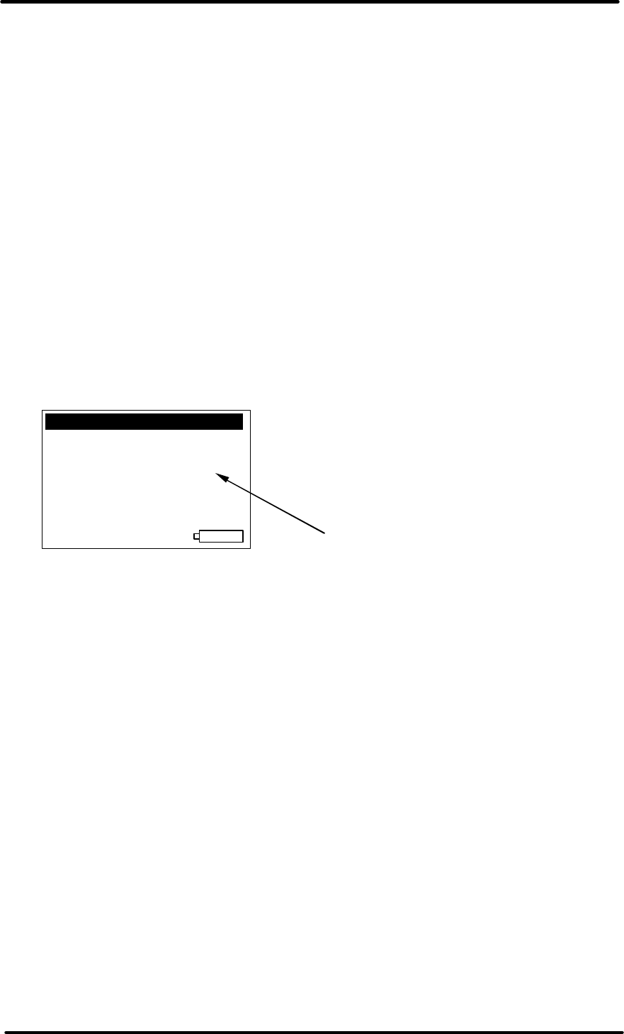
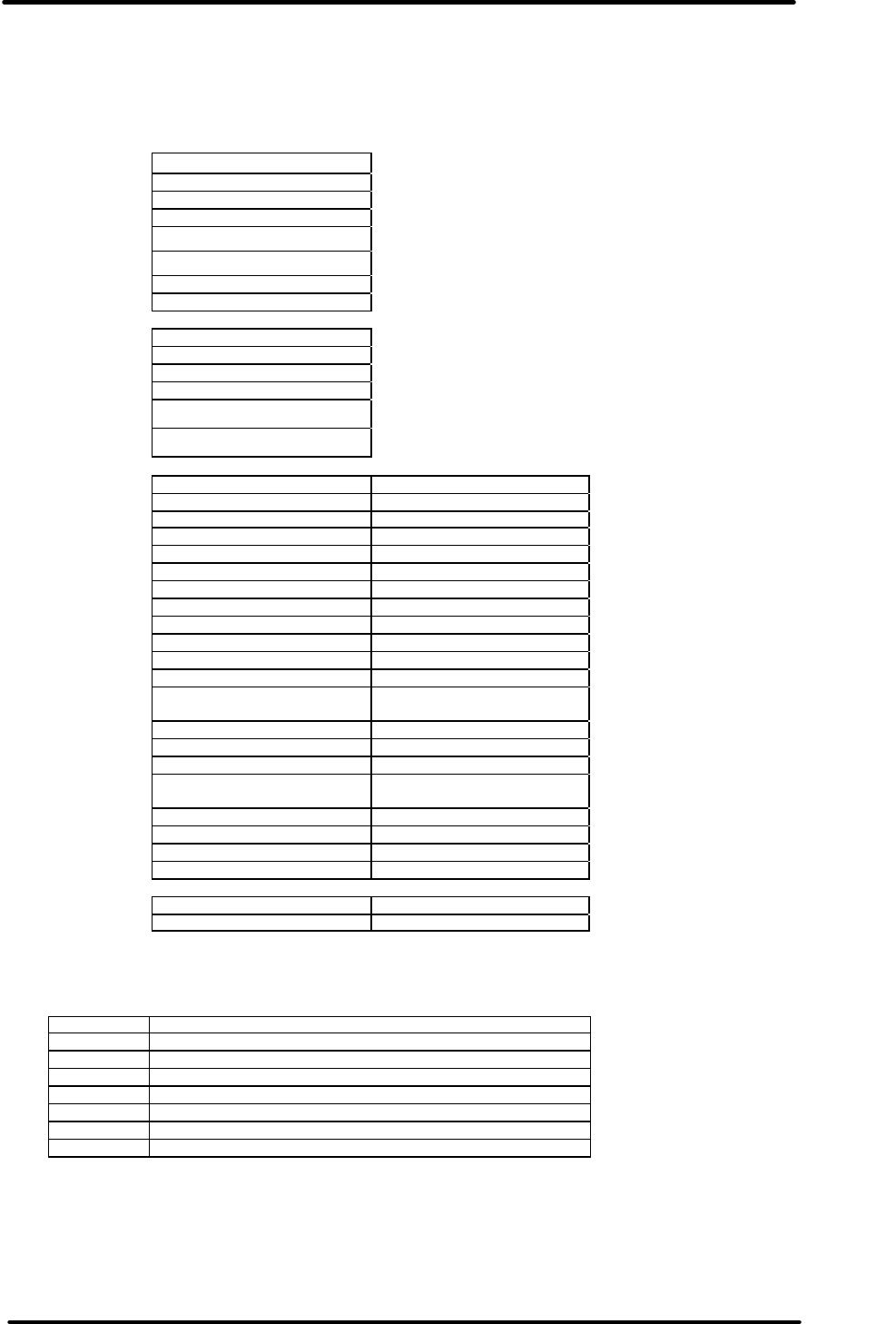
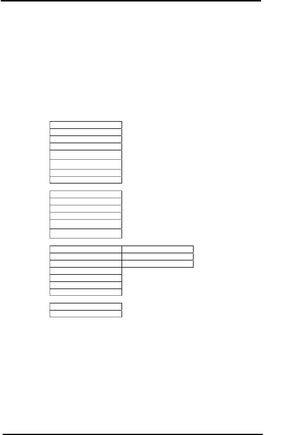
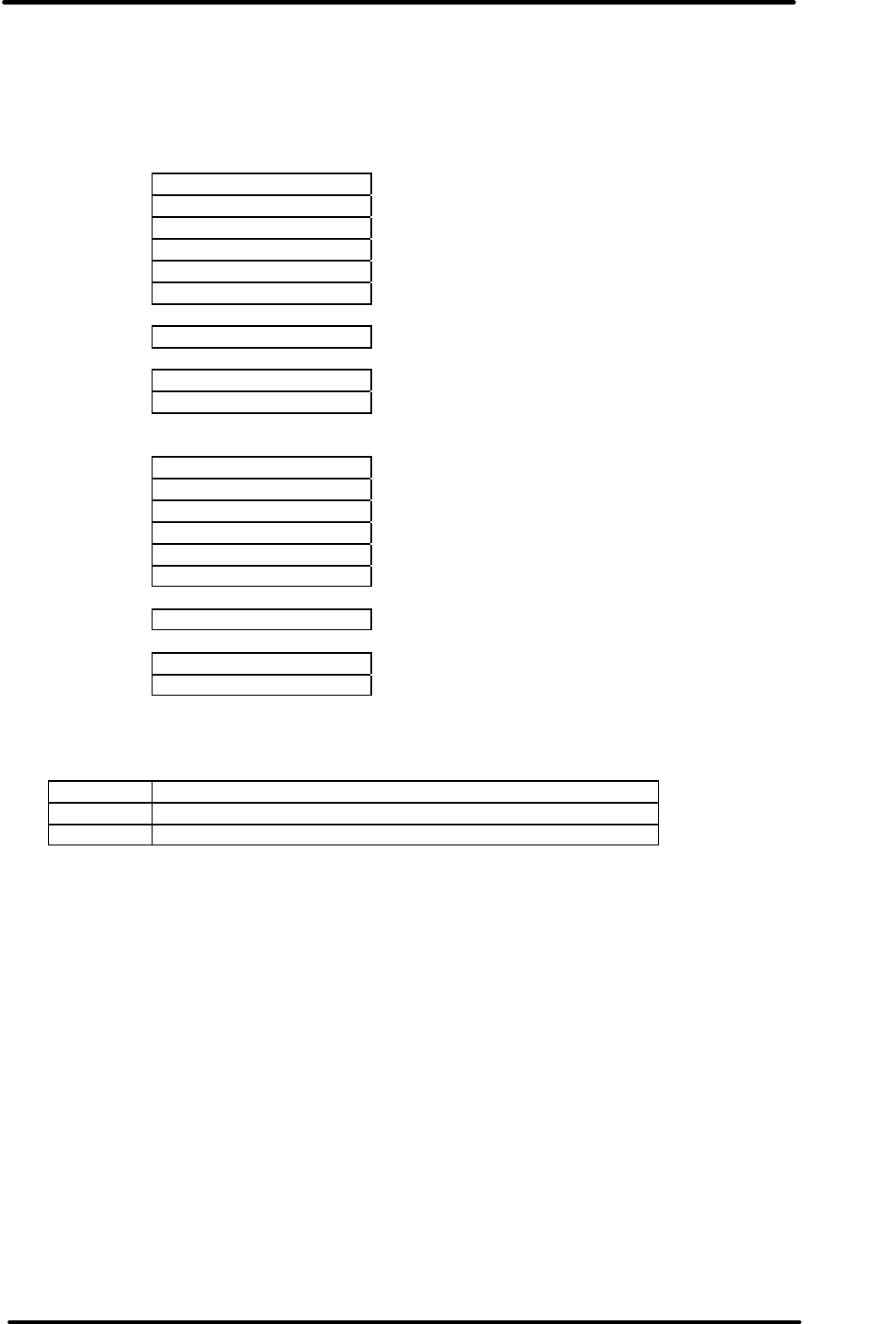
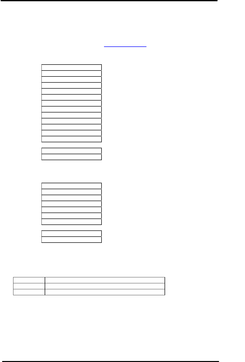
3.1 Menu 1 - Main menu
After a greeting screen this is the first menu the user sees after power on and all other menus
stem from here. The highlight bar defaults to the first option (Read new) so if the user is simply
collecting data all they need to do is keep pressing Select each time they approach a new logger.
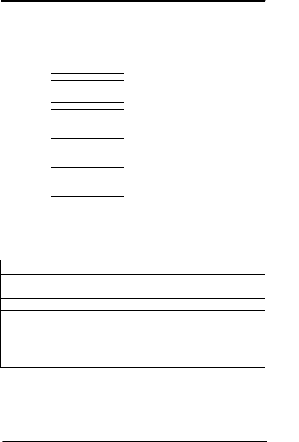
The menu options are :
Read new logger ( if selected go to screen 1.1)
Read all loggers ( if selected go to screen 1.1)
View data ( if selected go to Menu 2 )
Program logger ( if selected go to Menu 5 )
System options ( if selected go to Menu 6 )
'Read new' loggers means scan the local environment for all responding loggers but only retrieve
logger data from loggers that have not previously been downloaded.
'Read all' loggers means retrieve logger data from all loggers regardless of whether they have
been accessed before or not. This can result in more than one image of the logger being
available in memory.
At the bottom of the display the current time is shown and if the battery is low or is charging then
a battery symbol is shown to indicate this. If the battery is low the symbol flashes and if the
battery is charging the symbol repeatedly 'fills up'.
.
Read new
.
Read all
View data
Program logger
System Options
4:53pm
Initially removed

REDi TECHNICAL MANUAL
V1.4 5th December 2005 page 8 of 60
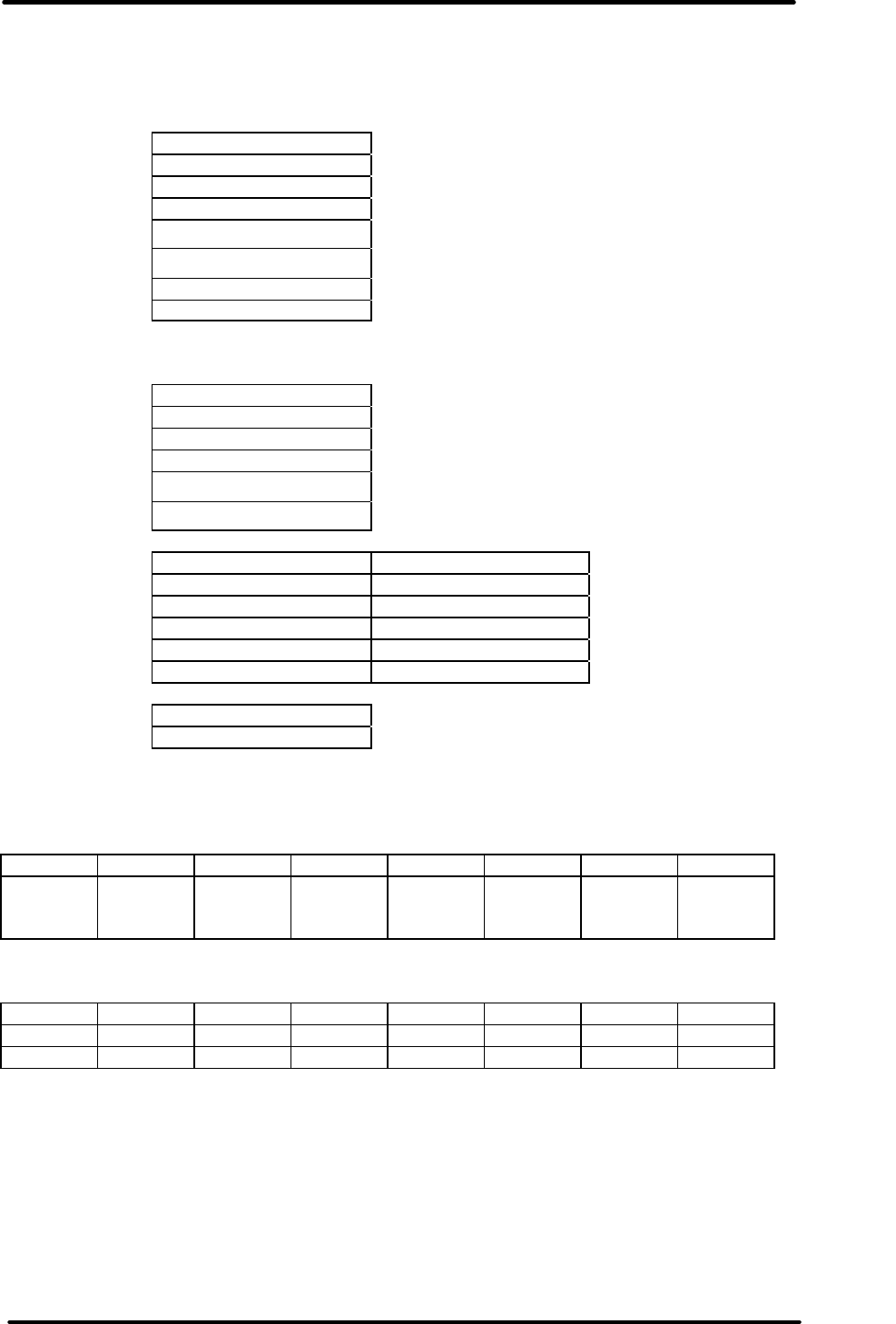
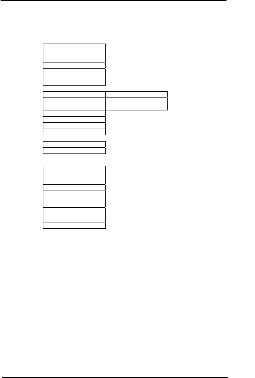
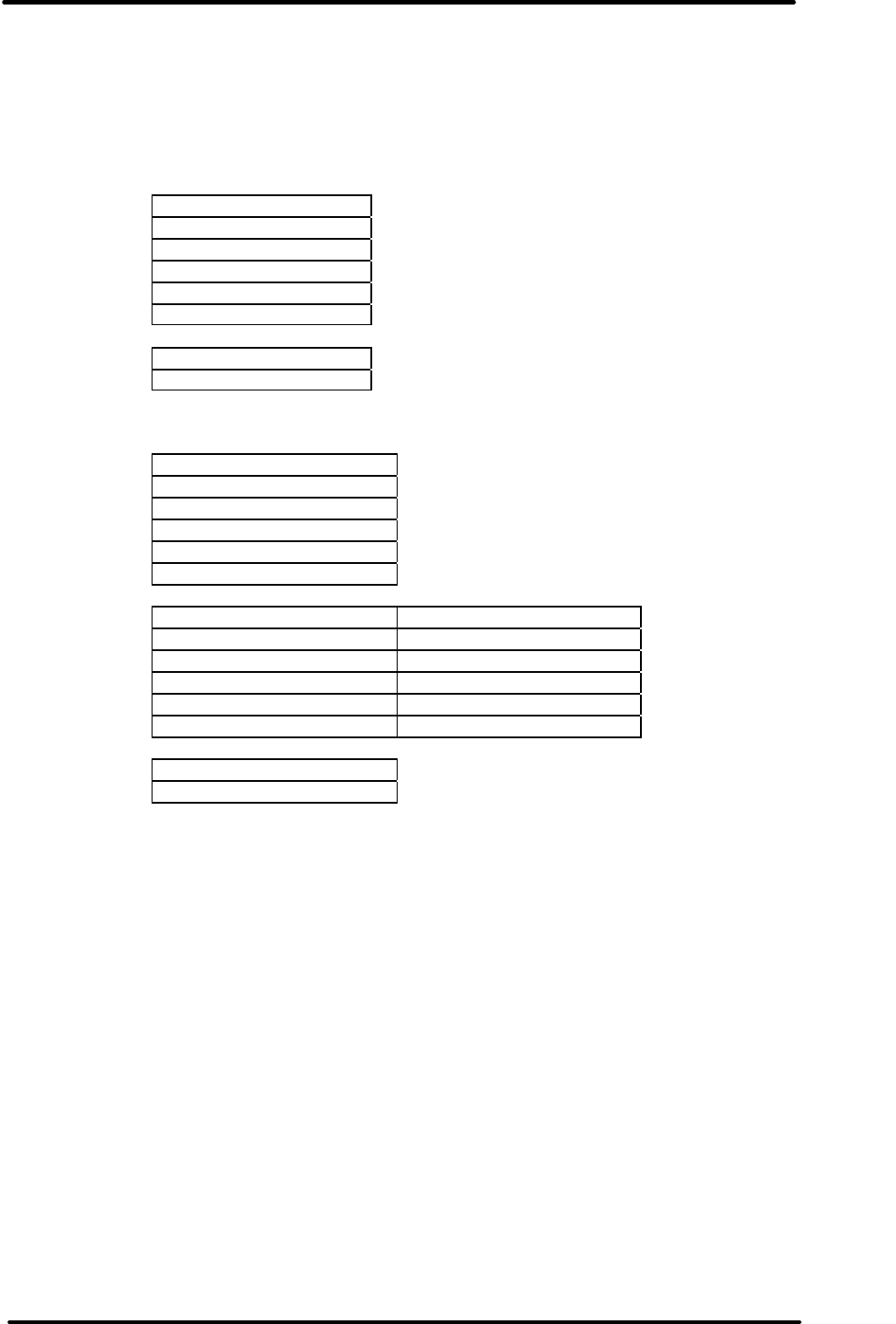
3.2 Screen 1.1 - Transfer progress
When attempting to upload a logger's data the various program cycles are sequentially shown as
in the following figures. If a valid connection is established the user will see the sequence shown
in Fig 3.2.1, 3.2.2, 3.2.3. After data is uploaded the display remains as shown in Fig 3.2.3 until the
user presses Select after which the display changes to Menu 2.
If a connection cannot be established then the message in figure 3.2.5 is displayed until the user
presses Select after which the display is returned to Menu 1.
Fig 3.2.1 Fig 3.2.2
Fig 3.2.3
Fig 3.2.4 Fig 3.2.5
Searching ...
Connected to
5 loggers
Reading (1/5)
MI-03-136-020
Connected to
5 loggers
(5/5)read
.OK. .
No loggers found
Searching ...

REDi TECHNICAL MANUAL
V1.4 5th December 2005 page 9 of 60
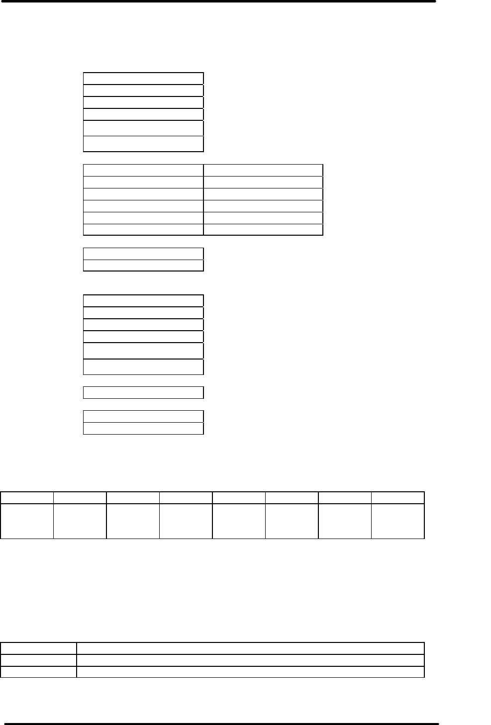
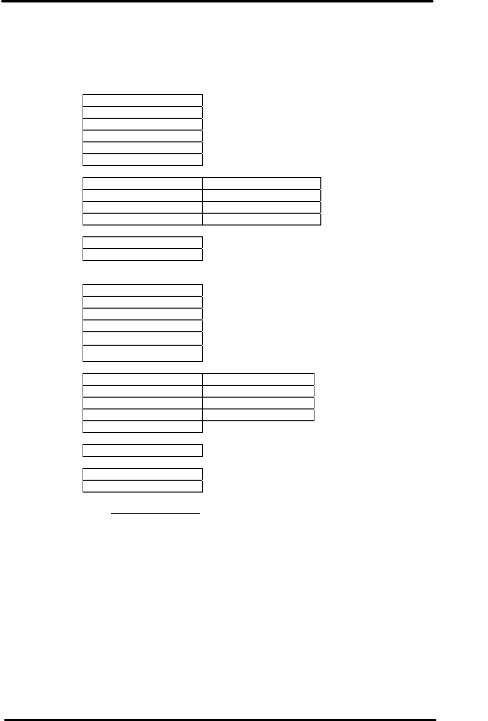
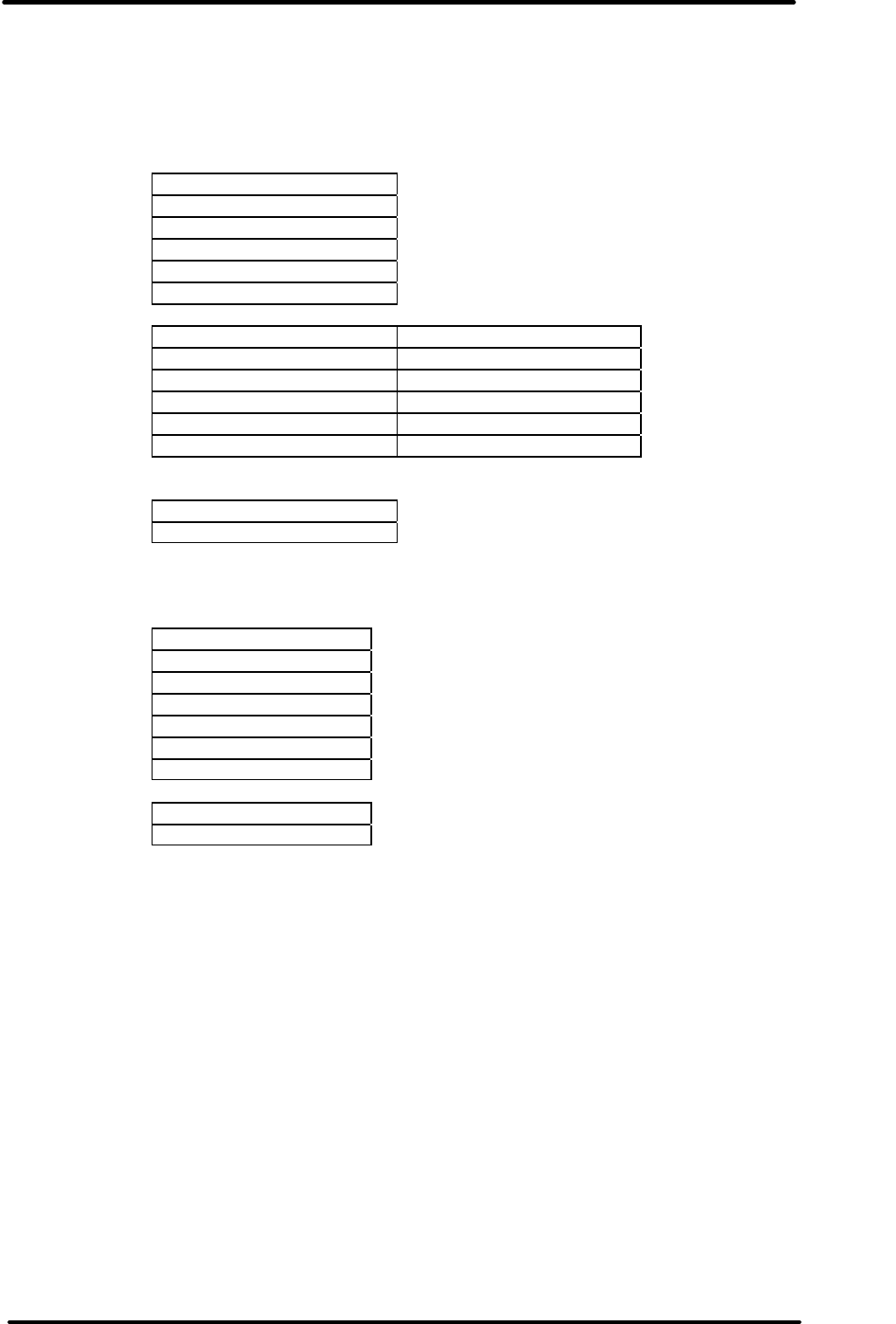
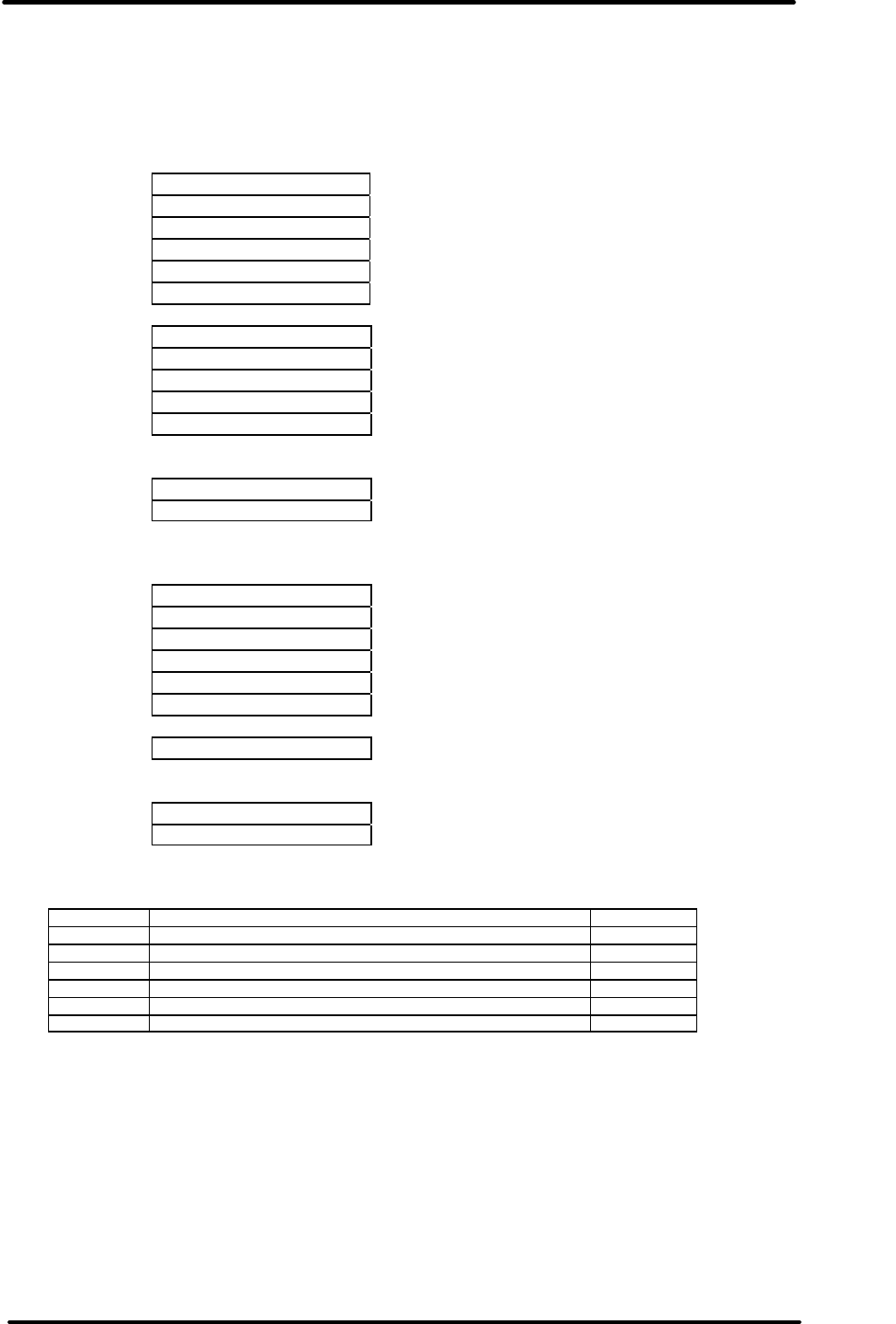
3.3 Menu 2 - Viewing of stored data
Fig 3.3.1
The user can choose to select a logger from a list of the most recently retrieved logger data or
from all the logger data stored in memory as shown in Fig 3.3.1. After the user selects this option
a summary of the details of each logger is shown in Menu 3.
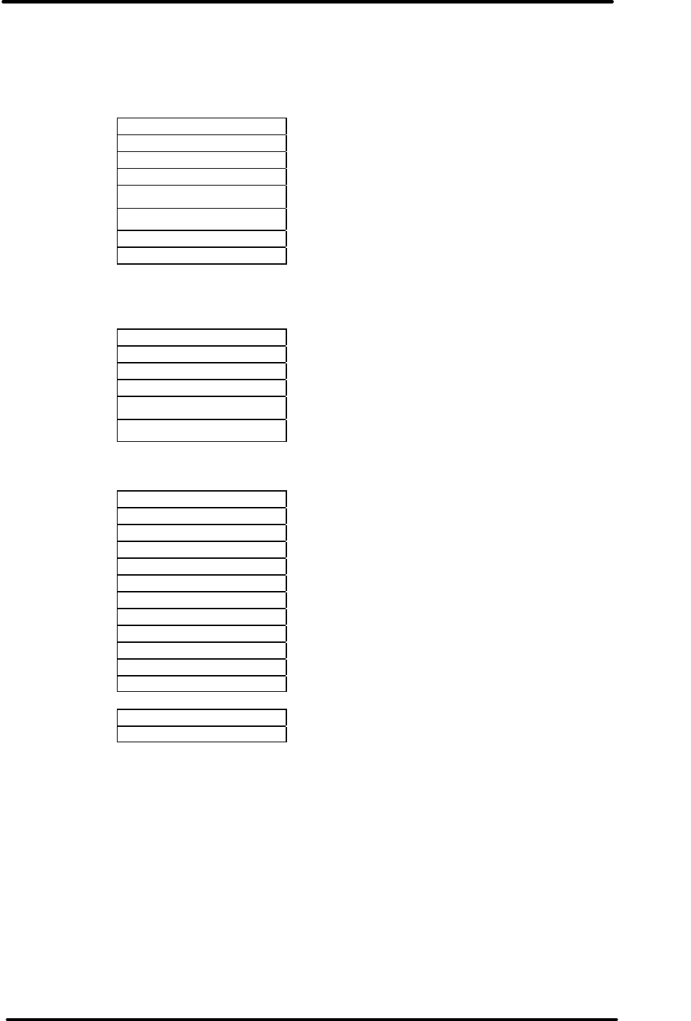
3.4 Menu 3 - Selection of previously stored data
This menu gives the user the option to review the data of any of the loggers that have been
downloaded so far. As shown in Fig 3.4.1 the user is viewing the last of 5 recently loaded loggers.
By pressing Left or Right the user can bring up the 'next' logger. If the user wishes to examine the
logger data in more detail then selecting 'View Summary' will move to Menu 4. If the user wishes
to view all readings that were out of specification then selecting "View Out Spec" will take them to
Menu 7.
Some loggers will also allow restarting. For these loggers an option 'Restart Logger' will appear in
the menu after 'View Out Spec'. For a description of this function refer to section 3.7.
Pressing the Escape key will take the user back to Menu 2. Scrolling down and selecting 'Exit' will
take the user back to Menu 1.
Fig 3.4.1 Selection of previously
stored data
.View recent .
View all
Exit
MI
-
IN
-
D
-
2
-
LR9
MI-BF-013-123
Description
Bat: Low
Stopped, PASS
.< (5/5) >.
View Summary
View Out Spec
Exit

REDi TECHNICAL MANUAL
V1.4 5th December 2005 page 10 of 60
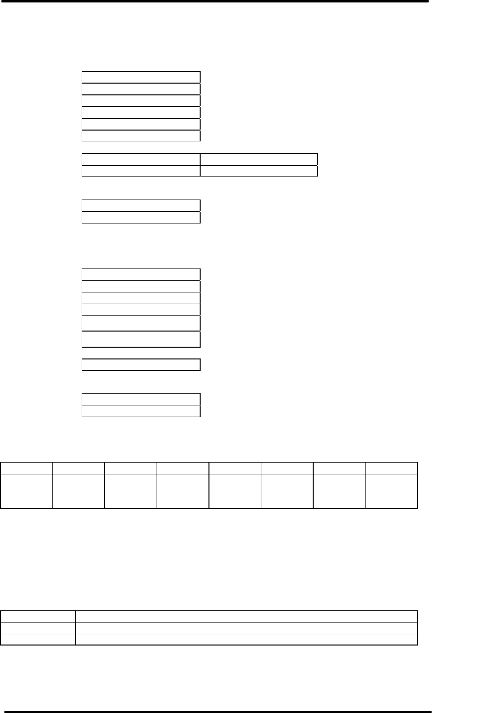
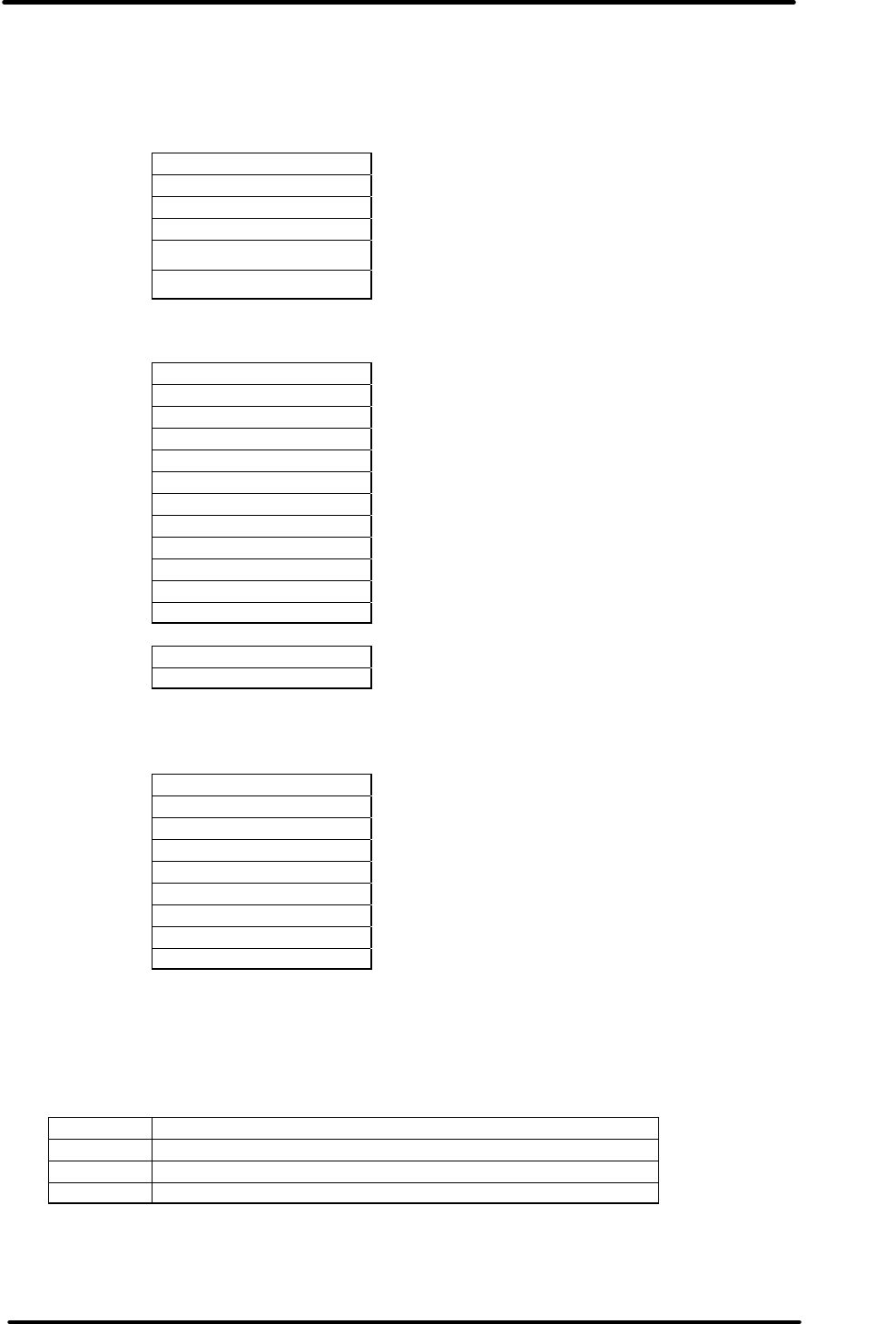
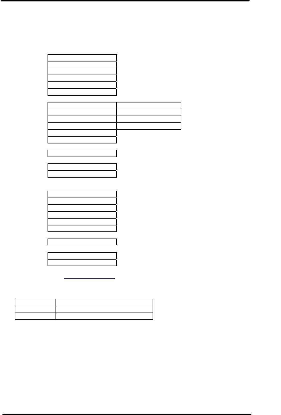
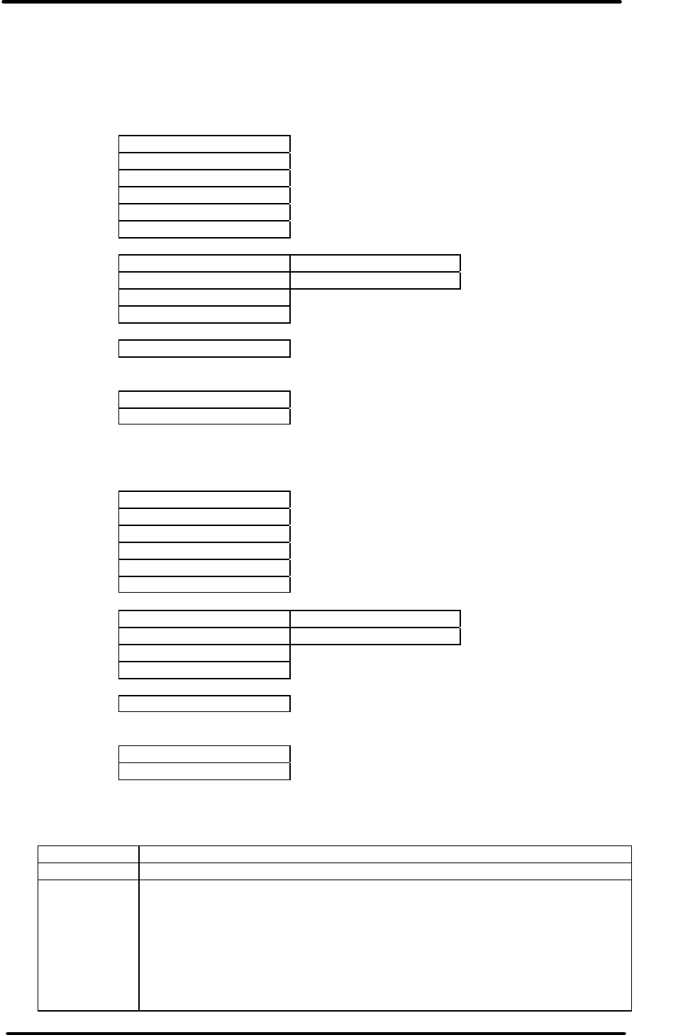
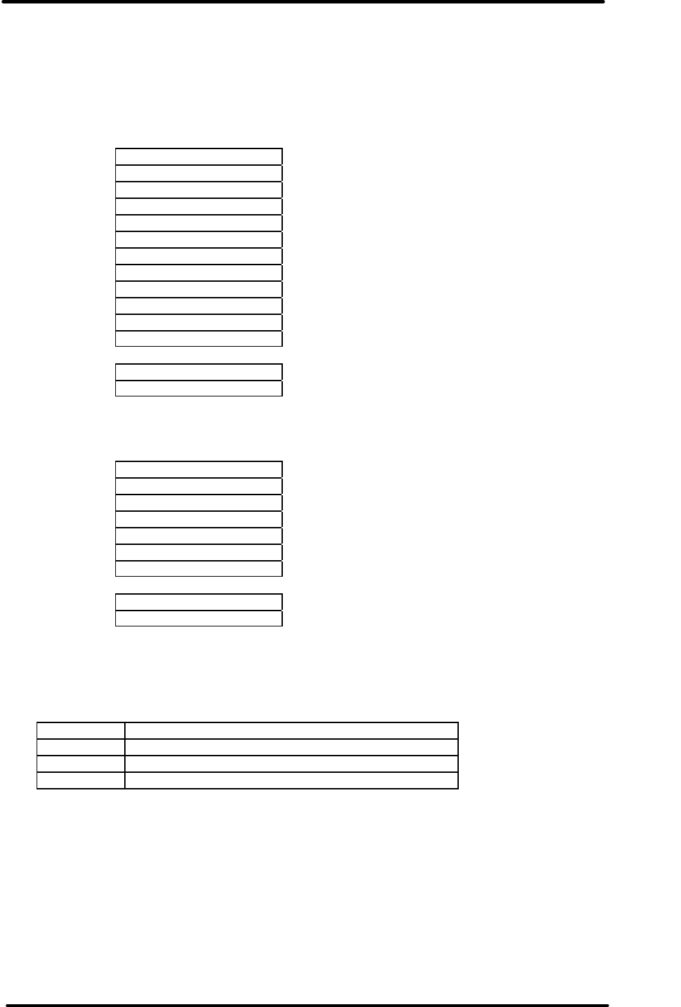
3.5 Menu 4 - Statistics
Menu 4 displays statistics about the logged data. The up and down keys scroll the highlight bar
and menu up and down as described above.
For a multi sensor logger the statistics are repeated for each sensor.
The menu is as follows :
Product name
Serial number
Description
Trip number
Battery status
Time zone
Sampling rate
Number of readings taken
Start time
End time
[ First sensor ]
Active range of the logger
High alarm level
Low alarm level
Maximum reading
Average reading
Minimum reading
Alarm status
Time spent above high alarm spec
Time spent below low alarm spec
Logger state (Ready, Stopped etc.)
[ Further sensors if applicable ]
View new logger ( if selected go to Menu 3 )
Exit ( if selected return to Menu 1)
eg.
and after scrolling down ..
Fig 3.5.1 Display of statistics
and after scrolling down ..
MI
-
IN
-
D
-
2
-
LR9
.
MI-BF-136-020
Description
Trip No: 2
Battery: OK
Time Zone:
GMT+12:00
Sampling: 2min
Readings: 1868
Start Time:
.
11/04/05 11:17
End Time:
14/04/05 01:31
Active:-40~70°C
High Spec:40.0°C
Low Spec:0.0°C
Max: 57.5°C
Avg: 13.5°C

REDi TECHNICAL MANUAL
V1.4 5th December 2005 page 11 of 60
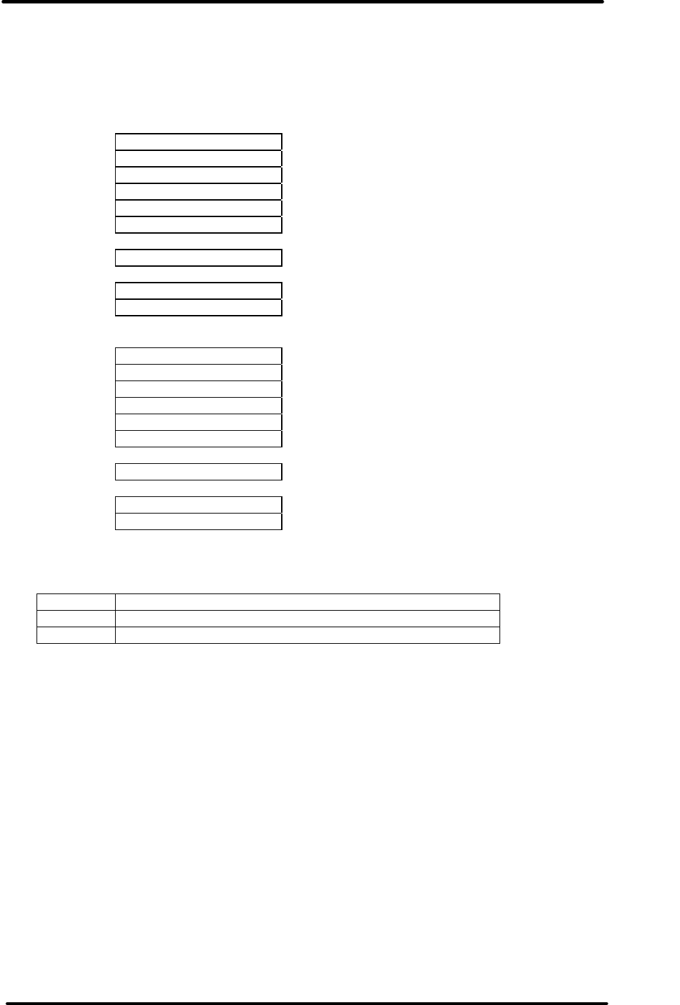
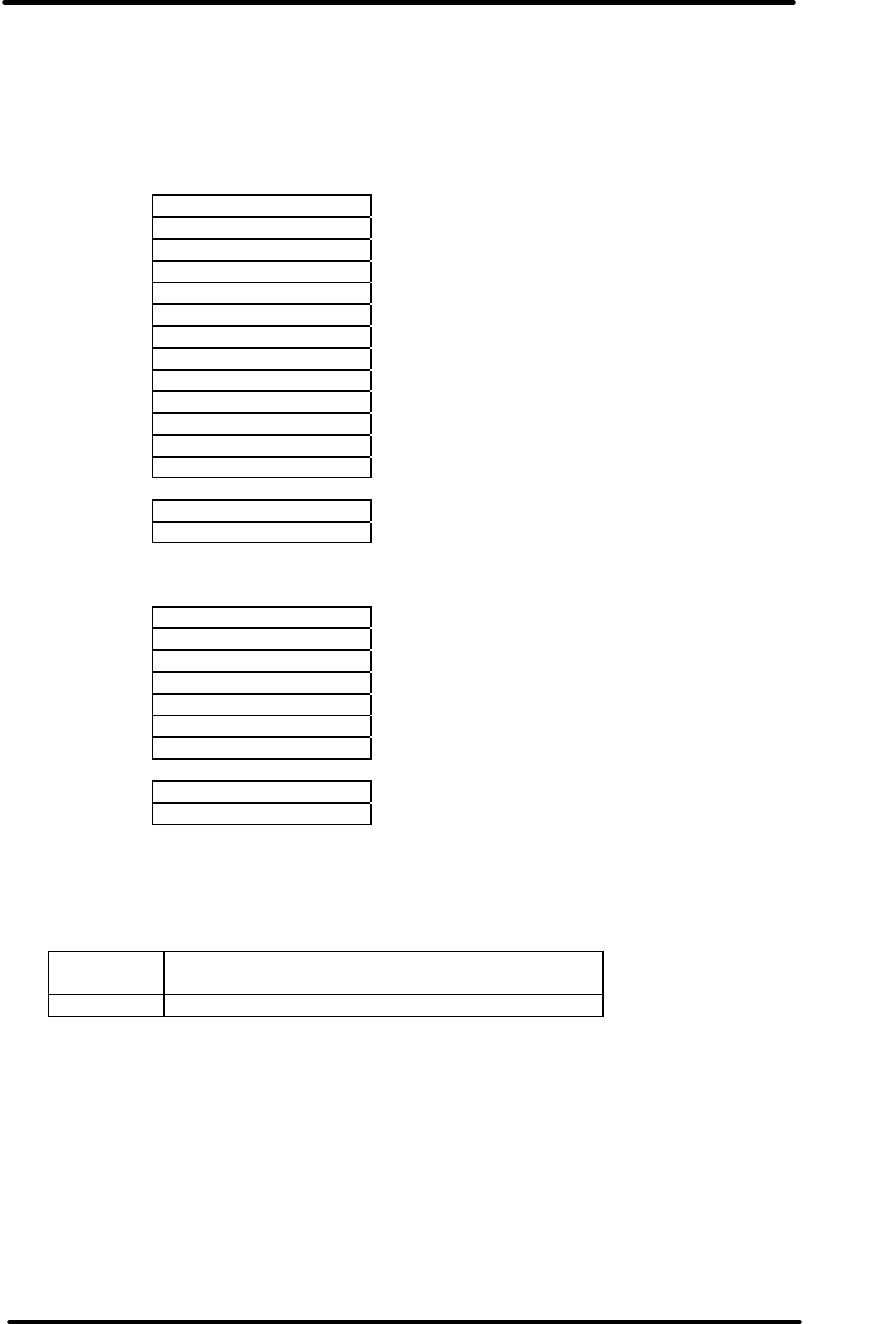
3.6 Menu 7 Out of specification readings
The user can generate a list of all out of spec readings that are present in the logged data from a
logger they have downloaded. An example of such a list is shown in Fig. 3.6.1
Fig. 3.6.1 Out of spec readings
Scrolling the highlight bar up or down can scroll the list up or down (the list is taller than the
screen) and moving the bar over "Next" and pressing Select will bring up the next
(chronologically) list of out of spec readings. Pressing Escape will return to Menu 3.
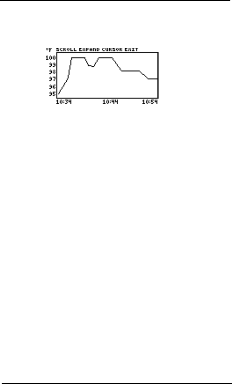
3.7 Graphical display
This feature has not been implemented.
This feature displays the data graphically and will look as shown in Fig 3.6.1. The display has a
menu across the top of the screen and either the menu is active (controlled by the keys) or the
display is. When graphical display mode is first entered the menu is active and pressing the left or
right arrow keys cycles through the four options (Scroll, Expand, Cursor, Exit) and Select selects
one.
By selecting Scroll the display immediately becomes active and the up and down arrow keys can
be used to scroll the data up and down the vertical temperature (or %RH etc) axis. Similarly the
left and right keys can scroll back and forth along the horizontal time axis. Pressing Select makes
the menu active again.
By selecting Expand the display immediately becomes active and the up key can be used to
expand the temperature axis while the down key can be used to contract this axis. Similarly the
left and right keys expand and contract the time axis. Pressing Select makes the menu active
again.
By selecting Cursor the display immediately becomes active and cross hairs appear. The left and
right keys move the vertical hair and the up and down keys move the horizontal hair.
Unfortunately the display is too small to practically display any information based on the cursors
Next
.
11/04/05 13:19
Reading: -3.0°C
11/04/05 13:21
Reading: -3.0°C
11/04/05 13:23
Reading: -3.0°C
11/04/05 13:25
Reading:
-
3.5
°
C
Min: -23.0°C .
Alarm: High+Low
Time over:40.0°C
16:02:00
Time under:40.0°C
1,01:46:00
State: Stopped
View new logger
Exit
REDi TECHNICAL MANUAL
V1.4 5th December 2005 page 12 of 60
so this is just an 'added value' feature - further brainstorming may make this more useful.
Pressing Select makes the cross hairs disappear and returns to active menu mode.
Selecting Exit returns to Menu 2.
Fig 3.7.1 Graphical display

REDi TECHNICAL MANUAL
V1.4 5th December 2005 page 13 of 60
3.8 Menu 5 - Reprogramming
As of 3rd August 2005 the REDi does not allow the operator to create and/or send a program to a
logger. The facility has been built into the RF protocol and all loggers are set up to receive a
program however the user interface side of reprogramming has yet to be discussed.
The REDi can, however, tell a logger to restart it's current program. This function is selected from
Menu 3 and can only be selected once a loggers data has been retrieved by REDi. The user is
warned that they will erase all existing data in that logger then, if they proceed, the logger is
instructed to flush it's statistics, rewind its address pointer and begin logging afresh.
If the logger is password protected then it will block any attempt to restart it. The REDi operator is
not given the option to enter a password.
If the logger is leased then it will decrement the lease count prior to restarting. If the lease has
expired then the logger will refuse to restart.
Depending on the response of the logger the REDi may display one of several messages listed
below.
"MI-XX-XXX-XXX Started."
Means everything occurred as expected and the logger has restarted.
"Starting MI-XX-XXX-XXX Failed."
Means there was some error and the logger has not restarted. The most likely cause is that the
logger is out of range of RF signals. It is also possible that the logger got part way through
restarting but some event caused it to abort the process. In this case the logger will have either
done nothing or have switched to Ready mode but not started. In either case it is safe to resend
the Restart command and the trip number and lease count will not be updated a second time.
"MI-XX-XXX-XXX is protected so NOT started."
The logger is password protected so is refusing to accept the Reprogram command.
"The lease of MI-XX-XXX-XXX has expired so NOT started."
The logger is leased and the lease has expired so the logger is refusing to accept the Reprogram
command.
"Command sent to MI-XX-XXX-XXX but response could not be confirmed."
The REDi sends a Restart command to the logger and then, after a couple of seconds, sends a
further command to the logger to read back confirmation that the program was in fact restarted.
This error message means that the Restart command was sent to the logger and the logger
acknowledged receipt of it, however the REDi lost communication with the logger and was unable
to confirm (either yes or no) that the logger was successful in restarting. In this circumstance it is
likely that the logger did indeed restart. If the operator simply sends the Restart command again
then the logger may restart a second time which generally will achieve the desired result but will
have increased the trip number by 2 and decreased the lease count by 2. To avoide this the
operator should find the logger and check it, or alternately download it's data again to check it's
state.

REDi TECHNICAL MANUAL
V1.4 5th December 2005 page 14 of 60
3.9 Menu 6 - System options
Using this menu the user can custom configure REDi system variables. These settings are stored
in non-volatile memory so will not be affected by a battery change.
The menu options are:
If Shut down is selected the unit immediately goes to sleep.
Auto off refers to the time before the unit automatically goes to sleep. This can be adjusted (left
and right arrow keys) in minutes from 1 to 30. The auto off function cannot be disabled.
Back-light time can be increased or decreased using the left and right arrow keys. This is the
amount of time that the back light remains on for after the last key press before automatically
turning off. It can be adjusted from 0 to 180 in steps of 5 seconds.
Mem left gives an indication of how full the memory is. It cannot be adjusted but, depending on
market requirements, a feature could be added allowing a user to purge readings to free up
memory.
Rechargeable allows the user to set whether the batteries that have been installed are
rechargeable batteries or not. If set to 'N' then the REDi will not attempt to recharge them.
Temp unit governs whether the temperature data is displayed as Celsius or Fahrenheit on the
REDi display. This only affects how readings are displayed. The conversion is done on the fly and
does not alter data records held in memory.
Erase all data, if enabled, allows the user to delete all records stored in memory. The user cannot
delete selected records.
System info brings up the 'splash screen' that is shown briefly after power up. This shows the
device description, firmware version, battery level, part number and serial number.
Selecting Exit will return to the main menu. Pressing Escape will also return to the main menu.
Shut down
.
AutoOff 10 min
Backlight 25 s
Mem left 1008k
Rechargeable Y
Temp Unit °C
Erase all data
System info
Exit

REDi TECHNICAL MANUAL
V1.4 5th December 2005 page 15 of 60
4. Memory Organisation
4.0 Introduction
The REDi provides two ways of accessing its internal memory from the PC. The first is direct
physical access and the second is through commands.
The PC can directly read and write to any address inside the REDi. This gives the PC the ability
to really screw things up so must be used carefully. In general, the user software should never
directly write to memory it should only ever read.
The primary method of access is through commands requesting or delivering certain blocks of
information. The REDi will gather or distribute the information from / to its internal memory and
control the locations.
The only exception to the command access is reading out a logger memory dump. In this case
the PC must lock the memory using a P_LOCKMEM command, request a list of addresses and
data lengths using the P_GETLOGTABLE command, read out the required data using the
P_RMEMREAD command then unlock the memory again using the P_UNLOCKMEM command.
The protocols are detailed in the section "5.0 Communications".
4.1 Internal structure
The REDi memory is organised as a collection of data blocks which are referenced using an
index table. The index is stored in a 2k E2 memory chip due to the number of expected write
cycles and has the structure shown in Fig. 4.1.1. The first 3 bytes of E2 indicate the amount of
Flash memory that remains free, above the last block used. The next two bytes indicate the next
free address in E2.
The first 1k of Flash is reserved for system use and stores system variables as well as some
scratch memory. The remaining 1023k holds data blocks.
Fig 4.1.1 EEPROM Memory structure
Name Size Description
MemFree 3 Flash memory remaining
TableTop 2 Next free address in this table
Cluster000 12 Memory block index
Cluster001 12 Memory block index
:
Cluster161 12 Memory block index
99 System variables (top of memory)
REDi TECHNICAL MANUAL
V1.4 5th December 2005 page 16 of 60
Fig 4.1.2 Memory block index structure
Name Size Description
Type of block 1 0x00 = Retrieved data record
0x01 = Program to download
0xE5 = Deleted (free) block - Note 1
0xFF = End-of-table marker
Type of log 1 Type of logger
S/N 4 Serial number, lowest addr first (LSB or
MSB depends on format in logger)
Address 3 The 3 byte flash address (LSB will be 0 as
all blocks start on a new 256-byte page)
Length 3 The exact size (not rounded up to a page)
Each memory block index is 12 bytes long which limits the number of blocks to 162 if a 2048 byte
memory chip is used with 5 bytes at the start and 99 bytes free at the end.
The type of blocks are :
Type Description
0 A complete memory dump that has been extracted from
a radio equipped logger.
1 A complete unalterable program, ready for sending to a
logger with the associated serial number. The structure
is still to be determined.
229 Indicates a purged block and more data may follow
255 Indicates an empty block and no more data follows this
Logger Type Code
Code Meaning
1 IntelliMini
5 iLog
$FF Reserved (uninitialised EEPROM, thus "No Logger")
Notes: 1. A block of free space is not reused until all blocks above it are freed. A "Defrag" can
be forced by calling the R_COMPACTMEM protocol.

REDi TECHNICAL MANUAL
V1.4 5th December 2005 page 17 of 60
4.2 DATABASE
While the REDi interprets the data read from each logger and displays information about the
logger on its display, the stored data is a raw memory dump and is not altered in any way. This
will be buffered verbatim and sent on to the PC when requested. It will be stored in memory in a
different way from the ChartReader (Compare to page 14 & 15 of ChartReader manual) and is as
follows.
Size Name Description
1 LoggerType LOGGERTYPE
3 Size
2 CRC
Size Name Description
18 Status reply
x Base
memory
x Log buffer Full 1868 bytes for iMini
Only memused for iLog
N Data
x
HMA Top 32 bytes for Junior
For the Intelligent Mini the exact data is :
Size Name Description
1 LoggerType 1
3 Size 2072
2 CRC
Size Name Description
18 Status reply 18 bytes from RAM nibble
address 0x8C to RAM nibble
address 0xAF inclusive
180 Base
memory Includes lookup table
1868 Log buffer
2066 Data
0
HMA
Note : The "Base memory" and "Log buffer" will always be 2048 bytes and will be the entire
contents of the EEPROM.
The CRC includes the LoggerType, Size and Data. Note that it is the third item and not the last
for firmware optimisation reasons.

REDi TECHNICAL MANUAL
V1.4 5th December 2005 page 18 of 60
For the iLog the exact data is :
Size Name Description
1 LoggerType 5
3 Size
2 CRC
Size Name Description
18 Status reply
768 Base
memory
x Log buffer
N Data
128
HMA Last X bytes of memory
Note : The "Base memory" and "Log buffer" will always be a contiguous section of memory from
address $0000 to the last valid log.
The HMA area will contain 128 bytes of humidity calibration. It will be present but blank for a non
humidity iLog.
The "Status reply" will contain the standard 12 byte Status reply padded to 18 bytes with zeros.
REDi TECHNICAL MANUAL
V1.4 5th December 2005 page 19 of 60
4.3 Memory reference
The REDi allows the PC to directly read and write memory. To do this the PC must define not
only an address and data length but also specify which memory bank is to be accessed. The
following table describes the available resources.
1. PHYSICALMEMID
Memory
ID Description
0 Reserved
1 FLASH memory
2 FLASH memory – external ?
$20 I2C bus 1 : EEPROM
$21 I2C bus 2 : RTC
$10 CPU RAM
$11 CPU ROM
$12 CPU Registers
Note
I2C devices
If the physical device is an I2C device then the ADDR entry is mapped as set out below:-
MSB LSB
I2C_device Type
0 = Normal, 1=Extended
Not used
I2CWORDADDR1
I2CWORDADDR2

REDi TECHNICAL MANUAL
V1.4 5th December 2005 page 20 of 60
4.4 Header Structure
REDi header structure as stored in the first 256 bytes of each logger image in Flash.
typedef struct PreLoggerHeader
{
uchar LoggerType; // 0x01 = RF Mini
uchar SerialNumber[4]; // as per Mini
uchar Address[3]; // not relevant in Flash copy
uchar Length[3]; // not relevant in Flash copy
uchar Description[25];
uchar BatStat; // 1 = OK, 0 = Low
ulong StartTime; // seconds since Midnight Dec 31 1999
ulong LoggingInterval; // in seconds
uchar StartTimeOffset; // day light saving in Geoffs strange format
ulong NumReadings;
ulong FirstLogAddress; // offset from the start of the loggers EEPROM dump
uint ProgramStatus; // same format as Mini
ulong MaxLoggingNum; // Num of logging to take
uint TripNum;
ulong StartDelay; // in seconds
uchar NumberOfSensors;
short Sens1UpperSpec; // temperature in "Mini format"
short Sens1LowerSpec;
short Sens1Max;
short Sens1Min;
short Sens1Avg;
ushint Sens1Alarm; // bit 0 = low alarm, bit 1 = high alarm
uchar Sens1AlarmDelay;
uchar Sens1Range; // 9 = D range, 17 = LCDMini Celsius, 18 = LCDMini Fahrenheit
short Sens2UpperSpec;
short Sens2LowerSpec;
short Sens2Max;
short Sens2Min;
short Sens2Avg;
ushint Sens2Alarm;
uchar Sens2AlarmDelay;
uchar Sens2Range;
uchar Sens3UpperSpec;
uchar Sens3LowerSpec;
short Sens3Max;
short Sens3Min;
short Sens3Avg;
ushint Sens3Alarm;
uchar Sens3AlarmDelay;
uchar Sens3Range;
short E2Offset; // not relevant in Flash copy
ushint Flags; // not relevant in Flash copy
} PreLoggerHeader;
Note :
uchar is 1 byte
ulong is 4 bytes LSB first
uint is 2 bytes LSB first
short is 2 bytes LSB first
ushint (unsigned short int) is 2 bytes LSB first

REDi TECHNICAL MANUAL
V1.4 5th December 2005 page 21 of 60
4.5 REDi Memory Map (f/w ver. 1.01f)
Structure of the data stored in the 2k EEPROM
Add. Name Description
0x00 3 MemLeft Amount of free Flash memory remaining
0x03 2 NextFree Next free address in the EEPROM where an index
to logger data can be stored
0x05 12x Start of index table The logger image index table (see section 4.1)
0x793 13 Not used
0x7A0 4 Serial Number The serial number of this REDi. 8 BCD digits.
YYWW.IIII
0x7A4 2 Product ID LSB: Minor is Product code 0 = REDi.
MSB: Brand code 0 = EDLS, [1 = Cox,] 2 = Digitron.
0x7A6 2 Hardware version 1=916, 2=868, 3=433MHz
0x7A8 4 Network address Available for REDi's on a multidrop network
Initially this will always be 0x0000
Upper 2 bytes not used
0x7AC 2 CRC CRC of the S/N, Product ID, H/W version and
Network address
0x7AE 1 Sensor type (Not used)
0x7AF 1 BackLight time Number of seconds before the backlight goes out
0x7B0 1 Auto off time Number of minutes before the REDi shuts down
0x7B1 1 Num Recent Number of loggers for the "View recent" option
0x7B2 1 Contrast Contrast setting (no longer used)
0x7B3 1 Temperature units "C" or "F" as an ASCII digit
0x7B4 6 Date format 5 digits, NULL terminated eg. "m-d-y", "d-m-Y"
0x7BA 2 Base year
0x7BC 9 Time format 8 digits NULL terminated eg. "12:00:00", "24:00".
Actually only second digit check for either 12 or 24
0x7C6 2 Last page refreshed Records the page to be refreshed in Flash for long
term data retention
0x7C8 1 Description length The length of the description in bytes
0x7C9 42 Description Description stored as ASCII
0x7F3 1 Not Used
0x7F4 1 Baud rate (Not used) hard coded at 9600 baud
0x7F5 1 RS232 timeout (Not used) hard coded at 2s
0x7F6 1 Preset battery type Bit 7 = Rechergeable
0x7F7 2 Low batt voltage level BCD, LSB first eg. 0x02, 0x35 means 2.35V
0x7F9 1 Disable watchdog Bit 0 : 1 = disable, 0 = enable
0x7FA 1 Crash recovery FALSE written here during normal power down
0x7FB 1 Password flags bit 5,6,7 - spare
bit 4 - the password is masked by asterisks
bit 3 - the user can erase data blocks
bit 2 - Password is NOT required
bit 1 - the user can re-program loggers
bit 0 - the user can list loggers
0x7FC 4 Password 4 ASCII digits (only 0-9 are valid)
Unless otherwise stated multibyte values are LSB at lower address.

REDi TECHNICAL MANUAL
V1.4 5th December 2005 page 22 of 60
4.6 Memory faults
There are various conditions that the REDi will detect which constitute a serious malfunction of
the device. Under normal operation these should never be seen and are displayed as "Internal
error #" where the # is one of the numbers listed below. These may be caused by hardware faults
or by incorrect or corrupt device set up.
# Description
1 Problem reading / writing EEPROM
2 Problem reading / writing EEPROM
3 Problem reading / writing EEPROM
4 Problem reading / writing Flash
5 Problem reading / writing Flash
6 undefined
7 undefined
8 Problem reading / writing EEPROM
9 Problem formatting the data just clocked in from a logger

REDi TECHNICAL MANUAL
V1.4 5th December 2005 page 23 of 60
5. COMMUNICATIONS
5.1 RS232 Overview
All RS232 communications to & from REDi are structured with the following format.
Header:-
$54 Start Character
Network Address 1
Network Address 2 Network Address characters
Control Char ControlCharacter
Numdata bytes (L)
Numdata bytes (H)
Data Section Data byte 1 1st Data byte
Data byte 2 2nd Data byte
:
Databyte n nth data byte
CRC
CRC (LSB) CRC LSB
CRC (MSB) CRC MSB
Notes
1. CRC used is CRC_CCITT (X16+X
12+X5+1)
2. Standard initial comms baud rate is 9600 baud. Negotiation up to 115k baud will then be
attempted.
3. Communications mode is 1 start bit, 1 stop bit, no parity.
4. Network address to be used in multidrop comms applications.
Will always reply to Network Address = 0, or its own network address.
5. It is stipulated that the control character in the expected reply will always be different to the
control character sent.
See Section 5.4 Communications Message Control Character Values

REDi TECHNICAL MANUAL
V1.4 5th December 2005 page 24 of 60
5.2 Communications Message Summary
Message Control Returns control
acknowledge Description
P_STATUS R_STATUS
Status Info Returns status summary of REDi - includes:
• Firmware version,
• Serial Number
• Product ID
• Hardware Version
• Memory allocation,
• battery voltage,
• current reading,
• diagnostic values
• max packet size
This is the first message sent to find out what’s there.
P_RCONFIG R_RCONFIG Returns general configuration settings for REDi.
P_SCONFIG R_SCONFIG Upload configuration settings to REDi.
P_GETRTC R_GETRTC Requests current RTC
P_SETRTC R_SETRTC Sets RTC including daylight saving info.
P_COMMSPROPS R_COMMSPROPS Returns max speed of comms and any other
properties that we can think of. Bit mapped
properties.
P_COMMSBAUDSET R_COMMSBAUDSET Sets comms speed. (bitmapped)
Comms returns to default speed (9600) after defined
non valid comms time.
P_COMMSPROPSET P_COMMSPROPSET Low level communications properties set.
P_LOCKMEM
R_LOCKMEM Locks the memory so that the PC can access it
without the REDi interfering
P_RMEMREAD R_RMEMREAD Raw random read defined memory device at defined
address.
P_RMEMWRITE R_RMEMWRITE Raw random Write to defined memory device at
defined address.
P_UNLOCKMEM R_UNLOCKMEM Unlocks the memory passing control back to REDi
P_FWLOAD_BOOT R_FWLOAD_BOOT Boots processor firmware load RAM program
P_GETCHARGER R_GETCHARGER Returns with current charger configuration
P_SETCHARGER R_SETCHARGER Sets charger's configuration
P_TEST R_TEST Performs requested diagnostic test on REDi
P_GETLOGTABLE R_GETLOGTABLE Obtains a list of all the logger memory dumps in
REDi
P_FLUSHLOGGER R_FLUSHLOGGER Deletes one memory dump from memory
P_SETLOGGER R_SETLOGGER Sends a logger memory dump to REDi
P_SETPROGRAM R_SETPROGRAM Sends a pre-formatted logger program to REDi
P_FLUSHPROGRAM R_FLUSHPROGRAM Deletes one program from memory
*Greyed out items are planned but not currently defined.
REDi TECHNICAL MANUAL
V1.4 5th December 2005 page 25 of 60
5.3 Communications Message Protocols
P_STATUS
This message is to be used as the first enquiry message to determine the type and firmware. All
multibyte quantities are "little endian" (lowest byte at lowest address).
Msg to unit:- $54 Start Character
0
0 Network Address
P_STATUS Control Character
0
0 Num data bytes = 0
CRC (LSB)
CRC (MSB)
Reply:-
Header: $54 Start Character
0
0 Network Address (either broadcast 0 or my NETWORKADDR)
R_STATUS Control Character
$40 Numdata bytes = 64
0
Data Section :
0
FWVER_MINOR FWVER_MAJOR
2
SERIALNUM (LSB) SERIALNUM
4
SERIALNUM SERIALNUM (MSB) Note 1
6
PRODUCTID_MINOR PRODUCTID_MAJOR Note 2
8
HARDWARE_VERSION 1=916, 2=868, 3=433MHz
10
NETWORKADDR (LSB) NETWORKADDR (MSB) Current Unique Network Addr
12
MEMSIZE (LSB) MEMSIZE for logger memory dumps etc.
14
MEMSIZE MEMSIZE (MSB)
16
FREEMEM (LSB) FREEMEM free memory remaining
18
FREEMEM FREEMEM (MSB)
20
0 0
22
0 0
24
BATTERYVOLTS_LSB BATTERYVOLTS_MSB BCD format xx.xx
0xFFFF if reading fails
26
0 0
28
SYSTEM_STATUS_L SYSTEM_STATUS_M Note 3
30
0 0
32
MEMORY_STS MEMORY_STS 0=unlocked, 1 locked by M16,
2 = locked by PC
34
BUILD_NUMBER_L BUILD_NUMBER_M 16-bit int
36
1 = SAFE_MODE PASSWORD FLAGS
38
PASSWORD_1 PASSWORD_2
40
PASSWORD_3 PASSWORD_4
: :
62
0 0
CRC (LSB) CRC (MSB) CRC
Notes
1. The serial number of the unit. (XXXX.XXXX). BCD format YYWW.IIII.
2. Product ID: Major is Brand code 0 = EDLS, [1 = Cox,] 2 = Digitron.
Minor is Product code 0 = REDi.
3. System Status
Bit # Meaning of SET bit
0 External Power connected
1 Battery Overtemp warning (discontinued)
2 Charging now
3 Rechargeable batteries fitted
4 Charger suspended (e.g. no battery, or faulty battery detected)
5 Required password has not been entered correctly (into REDi)
6-15 Clear (always 0)
REDi TECHNICAL MANUAL
V1.4 5th December 2005 page 26 of 60
P_COMMSPROPS
Provides communications properties of unit.
Message to unit:-
$54 Start Character
0
0 Network Address
P_COMMSPROPS Control Character
0
0 Num data bytes = 0
CRC (LSB)
CRC (MSB)
Reply:-
Header: $54 Start Character
0
0 Network Address
R_COMMSPROPS Control Character
12 Numdata bytes.
0
Data Section :
BAUDRATEMAP Reserved (0) Note 1
DF_BAUDRATEMAP Reserved (0) Note 2
MAX_MSGNUMBYTES MAX_MSGNUMBYTES Note 3
NETWORKADDR (LSB) NETWORKADDR Note 4
RESETTIMEOUT Reserved (0) Note 5
INTERCHAR TIMEOUT 0 Note 6
CRC CRC (LSB) CRC LSB
CRC (MSB) CRC MSB
Notes
1. BAUDRATEMAP : bit mapped properties showing available baud settings:-
Bit7 Bit6 Bit5 Bit4 Bit3 Bit2 Bit1 Bit0
115k2
57k6
38k4
19k2
9600
921k6
460k8
230k4
2. DF_BAUDRATEMAP: Current System Default is 9600. Shown with bit set in 9600 field.
Bit7 Bit6 Bit5 Bit4 Bit3 Bit2 Bit1 Bit0
115k2 57k6 38k4 19k2 9600 921k6 460k8 230k4
0 0 0 0 1 0 0 0
3. MAX_MSGNUMBYTES: The max number of bytes allowed in a message data section. (both
for TX & RX)
4. Network ID
5. RESETTIMER : Number of 10th of seconds of no or invalid messages before resetting comms
to default..
6. INTERCHAR TIMEOUT : timeout value between characters during reception. (units to be
defined but probably 1 ms)
REDi TECHNICAL MANUAL
V1.4 5th December 2005 page 27 of 60
P_COMMSPROPSET
Message to set the settable communications properties.
Message to unit:-
$54 Start Character
0
0 Network Address
P_COMMSPROPSET Control Character
12 Num data bytes = 12
0
Data Section :
0 0
DF_BAUDRATEMAP 0 Note 1
0 0
NETWORKADDR NETWORKIDADDR Note 3
RESETTIMEOUT 0 Note 2
INTERCHAR TIMEOUT 0 Note 4
CRC CRC (LSB) CRC LSB
CRC (MSB) CRC MSB
Reply:-
$54 Start Character
0
0 Network Address
R_COMMSPROPSET Control Character
1 Numdata bytes.
0
Data Section :
Return Code Note 5
CRC CRC (LSB) CRC LSB
CRC (MSB) CRC MSB
Notes
1. DF_BAUDRATEMAP : bit mapped baud settings:-
Bit7 Bit6 Bit5 Bit4 Bit3 Bit2 Bit1 Bit0
115k2
57k6
38k4
19k2
9600
921k6
460k8
230k4
Defines the default baud rate for the unit.
2. RESETTIMEOUT in 10ths of seconds 0.1 ~ 25.5 seconds. 0 = reset to default immediately.
3. NETWORKID : Sets the network id for the unit.
4. INTERCHAR TIMEOUT : future – we may need this.
5 Reply Message Return Codes:-
Reply message always at same speed as sent message.
Return Code Meaning
0 OK
1 Baud rate unavailable
REDi TECHNICAL MANUAL
V1.4 5th December 2005 page 28 of 60
P_COMMSBAUDSET
Message to set the comms to a new speed and timeout
Message to unit:-
$54 Start Character
0
0 Network Address
P_COMMSBAUDSET Control Character
4 Num data bytes = 4
0
Data Section :
BAUDRATEMAP 0 Note 1
RESETTIMEOUT 0 Note 2
CRC
CRC (LSB) CRC LSB
CRC (MSB) CRC MSB
Reply (at same speed as sent):-
Header:
$54 Start Character
0
0 Network Address
R_COMMSBAUDSET Control Character
1 Numdata bytes.
0
Data Section :
Return Code Note 3
CRC
CRC (LSB) CRC LSB
CRC (MSB) CRC MSB
Notes
1 BAUDRATEMAP : bit mapped baud settings:-
Bit7 Bit6 Bit5 Bit4 Bit3 Bit2 Bit1 Bit0
115k2
57k6
38k4
19k2
9600
921k6
460k8
230k4
Bit is set in field of required baud rate.
2 RESETTIMEOUT in 10ths of seconds 0.1 ~ 25.5 seconds.
1 Reply Message Return Codes:-
Reply message always at same speed as sent message.
Return Code Meaning
0 OK : next messages(s) will be at baud rate defined.
1 Baud rate unavailable
REDi TECHNICAL MANUAL
V1.4 5th December 2005 page 29 of 60
P_RCONFIG.
Protocol to read the general configuration of the REDi.
The configuration contains:-
• Degrees C or F display
• Date & Time format (MM/DD/[YY]YY or DD/MM/[YY]YY)
• General description string (max 42 characters)
• LCD contrast setting
• Backlight off time (if backlight installed)
• Automatic turn-off time.
Message to unit:-
$54 Start Character
0
0 Network Address
P_RCONFIG Control Character
0
0 Num data bytes = 0
CRC (LSB)
CRC (MSB)
Reply:-
Header: $54 Start Character
0
0 Network Address
R_RCONFIG Control Character
N Numdata bytes.
0
Data Section :
F | 0 | 0 | D | D | S | T | Y N|0|0|0|0|0|0|0 Note 1
AUTOOFFTIME BACKLIGHTOFFTIME Notes 3,4
LCDCONTRASTVAL 0 Note 5.
Numdescrchars Note 2
Descchar 1
:
Databyte n
CRC
CRC (LSB) CRC LSB
CRC (MSB) CRC MSB
Notes
1. Bit D : date format (1=US (MM/DD/YY), 0 = Euro (DD/MM/YY)
Bit F : 1 = temperatures in degrees F, 0 = temperatures in degrees C.
Bit Y : Set if year 4 digit, else 2 digit.
Bit T : Set if 24 hour time format, 0 if 12 hour format (am/pm).
Bit S: Display Seconds : 1 = disable
Bit N: Set if recharging of batteries is allowed
2. General description string that appears on opening screen banner and software printouts.
3. Automatic off time in minutes (1-255), 0 = no autooff time.
4. Backlight off time in 1 second units (1~255), 0 = no backlight off time.
5. LCD contrast setting.
REDi TECHNICAL MANUAL
V1.4 5th December 2005 page 30 of 60
P_SCONFIG.
Protocol to set the general configuration of the REDi.
Message to unit:-
$54 Start Character
0
0 Network Address
P_SCONFIG Control Character
N
0 Num data bytes
Data Section :
F | 0 | 0 | D | D | S | T | Y B | 0 | 0 | 0 | 0 | 0 | 0 | 0 Note 1
AUTOOFFTIME BACKLIGHTOFFTIME Notes 3,4
LCDCONTRASTVAL 0 Note 5.
Numdescrchars Note 2
Descchar 1
:
Databyte n
CRC
CRC (LSB) CRC LSB
CRC (MSB) CRC MSB
Reply:-
Header: $54 Start Character
0
0 Network Address
R_SCONFIG Control Character
1 Numdata bytes.
0
status 0 = OK, 1 = Error – I’ve stuffed it up for some reason
CRC (LSB)
CRC (MSB)
Notes
1. Bits D : date format (01=US (MM/DD/YY), 00 = Euro (DD/MM/YY)
Bit F : 1 = temperatures in degrees F, 0 = temperatures in degrees C.
Bit Y : Set if year 4 digit, else 2 digit.
Bit T : Set if 24 hour time format, 0 if 12 hour format (am/pm).
Bit S: Display Seconds : 1 = disable
Bit B: Battery type : 1 = rechargeable, 0 = non-rechargeable
2. General description string that appears on opening screen banner and software printouts.
3. Automatic off time in minutes (1-255), 0 = no autooff time.
4. Backlight off time in 0.5 seconds units (1~255), 0 = no backlight off time.
5. LCD contrast setting.
REDi TECHNICAL MANUAL
V1.4 5th December 2005 page 31 of 60
P_GETRTC
Provides current RTC registers
Message to unit:-
$54 Start Character
0
0 Network Address
P_GETRTC Control Character
0
0 Num data bytes = 0
CRC (LSB)
CRC (MSB)
Reply:-
Header:
$54 Start Character
0
0 Network Address
R_GETRTC Control Character
12 Numdata bytes.
0
Data Section (for P_GETRTC):
SECONDS
MINUTES
HOURS
DOW
DOM
MONTH
Year Code 0-3
YEAR (LSB)
YEAR (MSB)
0
0
0
CRC CRC (LSB) CRC LSB
CRC (MSB) CRC MSB
NOTE: All time values are in BCD.
REDi TECHNICAL MANUAL
V1.4 5th December 2005 page 32 of 60
P_SETRTC
Writes new values to RTC registers
Message to unit:-
$54 Start Character
0
0 Network Address
P_SETRTC Control Character
12
0 Num data bytes = 12
Data Section:
SECONDS
MINUTES
HOURS
DOW
DOM
MONTH
Year Code 0-3
YEAR (LSB)
YEAR (MSB)
0
0
0
CRC CRC (LSB) CRC LSB
CRC (MSB) CRC MSB
Reply:-
Header:
$54 Start Character
0
0 Network Address
R_SETRTC Control Character
1 Numdata bytes.
0
Status Note 1
CRC (LSB)
CRC (MSB)
NOTE: All time values are in BCD.
Notes :
1. Error Definition
0x00 OK (no error)
0x01 RTC hardware unavailable
0x02 invalid data (non BCD)
REDi TECHNICAL MANUAL
V1.4 5th December 2005 page 33 of 60
P_LOCKMEM
Protocol to lock one of the banks of REDi memory. This is used to effectively disable the user
from retrieving or deleting memory blocks while the PC is accessing the memory.
Message to unit:-
$54 Start Character
0
0 Network Address
P_LOCKMEM Control Character
1 Num data bytes
0
Data Section : PHYSICALMEMID The ID of the memory block to lock
CRC (LSB) CRC LSB
CRC (MSB) CRC MSB
Reply:-
$54 Start Character
0
0 Network Address
R_LOCKMEM Control Character
1 Numdata bytes.
0
Data Section :
Error Code Note 1
CRC CRC (LSB) CRC LSB
CRC (MSB) CRC MSB
Notes :
1. Error Definition
0x00 Memory successfully locked
0x01 Memory cannot be locked
REDi TECHNICAL MANUAL
V1.4 5th December 2005 page 34 of 60
P_RMEMREAD
Provides raw read of specified physical memory device.
Message to unit:-
$54 Start Character
0
0 Network Address
P_RMEMREAD Control Character
8 Num data bytes = 8
0
Data Section :
PHYSICALMEMID Not used Note 1
ADDR_LSB ADDR
ADDR ADDR_MSB Note 2
NUMBYTES NUMBYTES Note 3
CRC CRC (LSB) CRC LSB
CRC (MSB) CRC MSB
Reply:-
$54 Start Character
0
0 Network Address
R_RMEMREAD Control Character
N Numdata bytes.
N
Data Section :
PHYSICALMEMID I2C_ADDR Note 1
ADDR_LSB ADDR
ADDR ADDR_MSB Note 2
NUMBYTES NUMBYTES Note 3
Data byte1
:
Databyte n
CRC CRC (LSB) CRC LSB
CRC (MSB) CRC MSB
Notes
1 PHYSICALMEMID: Physical memory id.
2 Address in device : address limit is device dependant!
3 Numbytes to read (limits and boundaries over which read will operate are device dependant!)
REDi TECHNICAL MANUAL
V1.4 5th December 2005 page 35 of 60
P_RMEMWRITE
Provides raw write to specified physical memory device
Message to unit:-
$54 Start Character
0
0 Network Address
P_RMEMWRITE Control Character
n Num data bytes
n
Data Section : PHYSICALMEMID Not used Note 1
ADDR_LSB ADDR
ADDR ADDR_MSB Note 2
NUMBYTES NUMBYTES Note 3
Data byte1
Data byte2
:
Databyte n
CRC (LSB) CRC LSB
CRC (MSB) CRC MSB
Reply:-
$54 Start Character
0
0 Network Address
R_RMEMWRITE Control Character
1 Numdata bytes.
0
Data Section :
Return Code Note 4
CRC CRC (LSB) CRC LSB
CRC (MSB) CRC MSB
Notes
1 PHYSICALMEMID: Physical memory id.
2 Address in device : address limit is device dependant!
3 Numbytes to read (limits and boundaries over which read will operate are device dependant!)
4 Return Code Meaning
0 OK : Memory Write OK
F Fail: Hardware Error
REDi TECHNICAL MANUAL
V1.4 5th December 2005 page 36 of 60
P_UNLOCKMEM
Protocol to unlock memory after the PC has finished accessing it. Note that if this command is not
executed then the REDi is effectively disabled from retrieving any more logger images.
Message to unit:-
$54 Start Character
0
0 Network Address
P_UNLOCKMEM Control Character
1 Num data bytes
0
Data Section : PHYSICALMEMID The ID of the memory block to release
CRC (LSB) CRC LSB
CRC (MSB) CRC MSB
Reply:-
$54 Start Character
0
0 Network Address
R_UNLOCKMEM Control Character
1 Numdata bytes.
0
Data Section :
Error Code Note 1
CRC CRC (LSB) CRC LSB
CRC (MSB) CRC MSB
Notes :
1. Error Definition
0x00 Memory successfully unlocked
0x01 Memory cannot be unlocked
REDi TECHNICAL MANUAL
V1.4 5th December 2005 page 37 of 60
P_FWLOAD_BOOT
This protocol places the processor in the mode required for firmware upload into the processor
FLASH ROM.
Message to unit:-
$54 Start Character
0
0 Network Address
P_FWLOAD_BOOT Control Character
0
0 Num data bytes = 0
CRC (LSB)
CRC (MSB)
Reply :-
$54 Start Character
0
0 Network Address
R_FWLOAD_BOOT Control Character
0 Numdata bytes.
0
CRC (LSB) CRC LSB
CRC (MSB) CRC MSB
"Rewrite Mode" is a special processor mode in which firmware is copied into RAM and executed.
In this mode, the Flash ROM (which contains the firmware) can be reprogrammed just like any
flash memory. This feature allows the product firmware to be replaced "in the field". The above
command (if executed successfully) places the processor in this mode, and the communications
protocols are completely different from those used in the "normal" REDi mode. Please see the
ChartReader Technical Manual for a fuller description.
The command table is reproduced here, but may not be updated to follow future developments.
Command CODE Description
P_SET_KEYBOARD $77 Sets/Clears the keyboard beeper.
P_READ_PAGE $88 Reads a page of program memory.
P_WRITE_PAGE $99 Writes a page of program memory.
P_ERASE_BLOCK $AA Erases a block of program memory so that it can be
reprogrammed.
P_ERASE_ALL $BB Erases the entire program memory so that it can be
completely reprogrammed.
P_EXIT_REWRITE $CC Exits Reader from Rewrite mode via a software reset (back
into Run mode). Must be done once finished.
Note: The password feature is not used. If the message has a correct CRC and a correct
command byte, then it is executed.
REDi TECHNICAL MANUAL
V1.4 5th December 2005 page 38 of 60
P_GETCHARGER
Message to get charger parameters.
Message to unit:-
Header:
$54 Start Character
0
0 Network Address
P_GETCHARGER Control Character
0 Numdata bytes.
0
CRC
CRC (LSB) CRC LSB
CRC (MSB) CRC MSB
Reply:-
$54 Start Character
0
0 Network Address
R_GETCHARGER Control Character
12 Num data bytes = 12
0
Data Section :
CHARGERSTS 0 Note 1
MAXCHARGETIME (L) MAXCHARGETIME Note 2
CHARGETIMEOUT CHARGETIMEOUT Note 3
CHARGEBATTVOLTS CHARGEBATTVOLTS Note 4
MAXCHARGEBATTVOLTS MAXCHARGEBATTVOLTS
Note 5
RECHARGEBATTVOLTS RECHARGEBATTVOLTS
CRC
CRC (LSB) CRC LSB
CRC (MSB) CRC MSB
Notes
1. CHARGERSTS : bit 0 set if charger enabled.
2. MAXCHARGETIME: maximum time (in minutes) to fast charger battery (falls to trickle after
this)
3. CHARGETIMEOUT: Maximum time (in seconds) to charge without battery voltage change
(this option negated with implementation of charging voltage curve derivative inflection
detection)
4. CHARGEBATTVOLTS : Always charge to at least this voltage. (int value x 100)
5. MAXCHARGEBATTVOLTS: Never charge above this voltage. (Charge terminated) (int
value x 100)
6. RECHARGEBATTVOLTS : Initiate recharge when battery voltage falls to this value. (int
value x 100)
REDi TECHNICAL MANUAL
V1.4 5th December 2005 page 39 of 60
P_SETCHARGER
Message to set charger parameters.
Message to unit:-
$54 Start Character
0
0 Network Address
P_SETCHARGER Control Character
12 Num data bytes = 12
0
Data Section :
CHARGERSTS 0 Note 1
MAXCHARGETIME (L) MAXCHARGETIME Note 2
CHARGETIMEOUT CHARGETIMEOUT Note 3
CHARGEBATTVOLTS CHARGEBATTVOLTS Note 4
MAXCHARGEBATTVOLTS MAXCHARGEBATTVOLTS
Note 5
RECHARGEBATTVOLTS RECHARGEBATTVOLTS
CRC
CRC (LSB) CRC LSB
CRC (MSB) CRC MSB
Reply:-
Header:
$54 Start Character
0
0 Network Address
R_SETCHARGER Control Character
1 Numdata bytes.
0
Status 0 = this message is greyed so stop asking for this you bozo
CRC
CRC (LSB) CRC LSB
CRC (MSB) CRC MSB
Notes
1 CHARGERSTS : bit 0 set if charger enabled.
2 MAXCHARGETIME: maximum time (in minutes) to fast charger battery (falls to trickle after
this)
3 CHARGETIMEOUT: Maximum time (in sections) to charge without battery voltage change
(this option negated with implementation of charging voltage curve derivative inflection
detection)
4 CHARGEBATTVOLTS : Always charge to at least this voltage. (int value x 100)
5 MAXCHARGEBATTVOLTS: Never charge above this voltage. (Charge terminated) (int
value x 100)
6 RECHARGEBATTVOLTS : Initiate recharge when battery voltage falls to this value. (int
value x 100)
REDi TECHNICAL MANUAL
V1.4 5th December 2005 page 40 of 60
P_TEST
The PTEST protocol allows specific diagnostic tests to be performed and reported on in the unit.
Message to unit:-
$54 Start Character
0
0 Network Address
P_TEST Control Character
N Num data bytes depends on test
N
Data Section :
TESTTYPE 0 Note 1
NUMDATABYTES 0 Note 2
Data byte1
Data byte2
:
Databyte n
CRC
CRC (LSB) CRC LSB
CRC (MSB) CRC MSB
Reply:
Message to unit:-
$54 Start Character
0
0 Network Address
R_TEST Control Character
N Num data bytes depends on test
N
Data Section :
TESTTYPE 0 Note 1
NUMDATABYTES 0 Note 2
Data byte1
Data byte2
:
Databyte n
CRC
CRC (LSB) CRC LSB
CRC (MSB) CRC MSB
TESTTYPE Codes
TESTTYPE Meaning
1 Data Section Echoed back (i.e a PING)
4 WakeTestLogger - Will request a loggers data size (with serial number
defined by the first 5 bytes in the data section). If the logger does not
respond then it will broadcast a general WakeUp packet then request the
loggers data size again. The REDi will reply to the PC with True or False in
the data section of an R_TEST packet depending on whether the logger
responded or not. It also creates an array in the first few bytes of the serial
Flash which has the form PTL,PTH,R0L,R0H,R1L,R1H...R14L,R14H,0xFF
where PT is the packet type, R0 is the result code of the first attempt to talk

REDi TECHNICAL MANUAL
V1.4 5th December 2005 page 41 of 60
to the logger, R1 is the second etc. up to 15 attempts. The result code is :
0x0000 : if no reply at all
0x0001 : if everything looks fine
0x0002 : if all bytes had correct Manchester encoding but the CS was
wrong
0x0008 : if we got the preamble but the STX was wrong or never came
0xRRNN : where RR = 0x09 (timed out after NN bytes) and NN = the
number of bytes
0xRRNN : where RR = 0x00 and NN = the number of bytes up until a
Manchester error
5 GetTestLoggerStatus - Reads a status packet from the logger with serial
number defined by the first 5 bytes in the data section. It does not attempt
to wake the logger up. It first reads the lowest 64 bytes of EEPROM so that
the logger is forced to update its Status packet reply. It returns in the data
section of the R_TYPE packet:
0 : True or False depending on whether the logger replied or not
1: F/W version low byte
2: F/W version high byte
3: Battery status, 1 = OK, 0 = Low
6 DumpTestLoggerAndCheck - Reads the lowest 64 bytes of EEPROM from
the logger with serial number defined by the first 5 bytes in the data section
and checks for a specific pattern. This pattern is 0x12,0x34,0x56 at address
0x0024,0x0025,0x0026. It returns in the first byte of the data section of the
R_TYPE packet: 0 if no response from the logger, 1 if the logger responded
and the data was correct, 2 if the logger responded but the data was not
correct.
7 ReadTestLoggerCurrent - the same as GetTestLoggerStatus except it is for
the RF test jig and instead of measuring the battery status it measures it's
own current consumption (1 = high, 0 = OK)
8 PerformBackOffTest - Intended only for the REDi that is embedded in the
RF test jigs. This command causes the REDi to transmit a
HowMuchDataDoYouHave packet and record whether it got a good reply, a
corrupt reply or no reply at all. It does this 20 times. It then switches a 3dB
attenuator into the line just before the antenna and repeats 20
transmissions. It does this for 11 steps of 3dB (30dB total). The results are
returned to the PC in the data section of the R_TYPE packet as 11 blocks
of 3 bytes where each block of 3 bytes holds the number of replies in each
group of 20 transmissions that were OK, Corrupt or No reply.
In addition to this, after the REDi has sent and received the 11x20 packets it
measures the background noise 3 times with a built in RSSI then sends 5
packets and with any luck gets 5 replies from the DUT. During each reply it
reads the RSSI and records a measure of the loggers transmit power.
These results are returned in the R_TYPE packet data section as well.
Following the 11 x 3 bytes are 3 short integers relating to background noise
then 5 short integers relating to DUT transmit strength.
9 EnterTestMode - this puts the REDi into a mode where it pretends to be an
RF Mini so that it can be tested on the same RF test jig as a Mini. It will
respond to the PC immediately before entering this mode but once in this
mode will not monitor it's RS232 port. The response is 0x01 in the first byte
of the R_Type packet.
10 GetRSSI - Intended only for the REDi that is embedded in the RF test jigs.
This command causes the REDi to read the RSSI in the test jig and report
the results. It reads it 3 times and replies with 3 short integers in the data
section of the R_TYPE packet. The numbers are the actual ADC value that
is read.
11 ContinuousTransmitLoop - Intended only for the REDi that is embedded in
the RF test jigs. This function will transmit 20 packets then switch in the
next 3dB attenuation step. It is intended for calibrating / diagnosing the RF
test jigs. It continues until power is removed and will not react to RS232.
12 SendGoToSleep - Put the logger with serial number defined by the first 5

REDi TECHNICAL MANUAL
V1.4 5th December 2005 page 42 of 60
bytes in the data section to sleep.

REDi TECHNICAL MANUAL
V1.4 5th December 2005 page 43 of 60
P_GETLOGTABLE
The PGETLOGTABLE protocol enables the PC to see what logger and/or program images (if
any) are stored in the REDi. It can be thought of as a memory allocation table.
Message to unit:-
$54 Start Character
0
0 Network Address
P_GETLOGTABLE Control Character
0 Num data bytes
0
CRC
CRC (LSB) CRC LSB
CRC (MSB) CRC MSB
Reply:
Message to unit:-
$54 Start Character
0
0 Network Address
R_GETLOGTABLE Control Character
N Num data bytes (depends on table size)
N
Data Section :
Index (LSB) Unique identifier for this logger dump
Index (MSB) Note 1
Block type BLOCKTYPE
Logger type LOGGERTYPE
s/n (low logger addr) The four byte serial number (format
s/n depends on the type of logger)
s/n
s/n (high logger addr)
Address (LSB) Location in flash memory
Address
Address (MSB)
Buffer size (LSB) Size of the logger data (in bytes)
Buffer size
Buffer size (MSB)
:
( Further loggers ) 14 bytes each, as above
CRC
CRC (LSB) CRC LSB
CRC (MSB) CRC MSB
Notes :
1. This is a zero-based index number, which is needed for reference when using
GET/SET/FLUSH LOGGER, GET/SET/FLUSH PROGRAM etc. There may be several images of
the same logger in memory so the serial number cannot be used as a reference. Note that there
may also be different types of logger with a given serial number.
REDi TECHNICAL MANUAL
V1.4 5th December 2005 page 44 of 60
P_FLUSHLOGGER
The FLUSHLOGGER command enables the PC to free up memory inside the REDi by deleting
the memory dump of a certain logger. The logger is referenced by index and the type and serial
number are compared before deleting.
The index number (required) is obtained from P_GETLOGTABLE.
Message to unit:-
$54 Start Character
0
0 Network Address
P_FLUSHLOGGER Control Character
5 Num data bytes
0
Index (LSB)
Index (MSB)
LOGGERTYPE
s/n (LSB)
s/n
s/n
s/n (MSB)
CRC
CRC (LSB) CRC LSB
CRC (MSB) CRC MSB
Reply:
$54 Start Character
0
0 Network Address
R_FLUSHLOGGER Control Character
1 Num data bytes
0
Error code Note 1
CRC
CRC (LSB) CRC LSB
CRC (MSB) CRC MSB
Note
1. Error Meaning
0 No error - Logger flushed
1 Internal problem, contact supplier
2. Once a logger is flushed, the logger index table is changed, so it should be re-read if required.
REDi TECHNICAL MANUAL
V1.4 5th December 2005 page 45 of 60
P_SETPASSWORD
The SETPASSWORD command enables the PC to set the Flags byte and the 4-byte password
itself.
Message to unit:-
$54 Start Character
0
0 Network Address
P_SETPASSWORD Control Character
5 Num data bytes
0
Data Section :
Flags byte See Note 1.
1st char New password, see Note 2.
2nd char
3rd char
4th char
CRC
CRC (LSB) CRC LSB
CRC (MSB) CRC MSB
Reply:
$54 Start Character
0
0 Network Address
R_SETPASSWORD Control Character
1 Num data bytes = 1
0
Data Section :
Failure code 0 = Success
CRC
CRC (LSB) CRC LSB
CRC (MSB) CRC MSB
1. Password flags
Bit # Meaning of SET bit Initial value
0 This REDi can list any logger 1
1 This REDi can program/rearm/restart any logger 1
2 REDi operator password is not required 1
3 User can erase logger data without the PC 0
4 Password entry is not displayed on REDi (masked by asterisks) 0
5-7 Available for use by software 0
2. There is as yet no specification on the allowed characters. Initially, exactly 4 digits are required,
because this is generated by the firmware when the user logs in. It is expected that upper- and
lower-case letters will also be permissible (i.e. enterable at login time). It should also be easy
to allow a variable length string of up to 4 characters, either with a null terminator or with all
unused characters set to null. As a consequence, it is easily possible to set a password which
cannot be entered, thereby preventing anyone from using the REDi. For maximum future
expansion, it is currently implemented as 1 ASCII code per byte. Default value after
initialisation is "0000" (0x30303030).
REDi TECHNICAL MANUAL
V1.4 5th December 2005 page 46 of 60
P_SETPROGRAM
The PSETPROGRAM command allows the PC to write a program to the REDi memory.
Obviously this will only end up in a logger when the user sends it to one.
Message to unit:-
$54 Start Character
0
0 Network Address
P_SETPROGRAM Control Character
5 Num data bytes
1
LOGGERTYPE The type of logger the program is for
s/n (LSB) The serial number of the logger
s/n
s/n
s/n (MSB)
Program 256 bytes of program information
CRC
CRC (LSB) CRC LSB
CRC (MSB) CRC MSB
Reply:
Message to unit:-
$54 Start Character
0
0 Network Address
R_SETPROGRAM Control Character
1 Num data bytes
0
Error code Note 1
CRC
CRC (LSB) CRC LSB
CRC (MSB) CRC MSB
Note
1. Error Meaning
0 Success - Program stored
1 Fail - internal problem, contact supplier
2 Fail - A program already exists for this type and s/n
REDi TECHNICAL MANUAL
V1.4 5th December 2005 page 47 of 60
P_FLUSHPROGRAM
The PFLUSHPROGRAM command allows the PC to delete a program at random from the REDi
memory.
Message to unit:-
$54 Start Character
0
0 Network Address
P_FLUSHPROGRAM Control Character
7 Num data bytes
0
Index(LSB)
Index(MSB)
LOGGERTYPE The type of logger the program is for
s/n (LSB) The serial number of the logger
s/n
s/n
s/n (MSB)
CRC
CRC (LSB) CRC LSB
CRC (MSB) CRC MSB
Reply:
$54 Start Character
0
0 Network Address
R_FLUSHPROGRAM Control Character
1 Num data bytes
0
Error code Note 1
CRC
CRC (LSB) CRC LSB
CRC (MSB) CRC MSB
Note
1. Error Meaning
0 Program successfully flushed
1 Internal problem, contact supplier
2. Once a logger is flushed, the logger index table is changed, so it should be re-read if required.

REDi TECHNICAL MANUAL
V1.4 5th December 2005 page 48 of 60
5.3 Communications Message Control Character Values.
Poll control command Value
($) Reply control acknowledge Value
($)
P_STATUS A0 R_STATUS with Status Info A1
P_RCONFIG A2 R_RCONFIG A3
P_SCONFIG A4 R_SCONFIG A5
P_GETRTC B4 R_GETRTC B5
P_SETRTC B6 R_SETRTC B7
P_COMMSPROPS B8 R_COMMSPROPS B9
P_COMMSBAUDSET BA R_COMMSBAUDSET BB
P_COMMSPROPSET BC R_COMMSPROPSET BD
P_LOCKMEM D0 R_LOCKMEM D1
P_RMEMREAD E2 R_RMEMREAD E3
P_RMEMWRITE E4 R_RMEMWRITE E5
P_UNLOCKMEM D6 R_UNLOCKMEM D7
P_FWLOAD_BOOT F0 R_FWLOAD_BOOT F1
P_GETCHARGER A6 R_GETCHARGER A7
P_SETCHARGER A8 R_SETCHARGER A9
P_TEST AA R_TEST AB
P_GETLOGTABLE BE R_GETLOGTABLE BF
P_SETLOGGER B2 R_SETLOGGER B3
P_FLUSHLOGGER C8 R_FLUSHLOGGER C9
P_SETPASSWORD CA R_SETPASSWORD CB
P_SETPROGRAM CC R_SETPROGRAM CD
P_FLUSHPROGAM CE R_FLUSHPROGAM CF
Greyed out means messages are not yet implemented.
REDi TECHNICAL MANUAL
V1.4 5th December 2005 page 49 of 60
6.0 Radio communications
6.1 Datastream
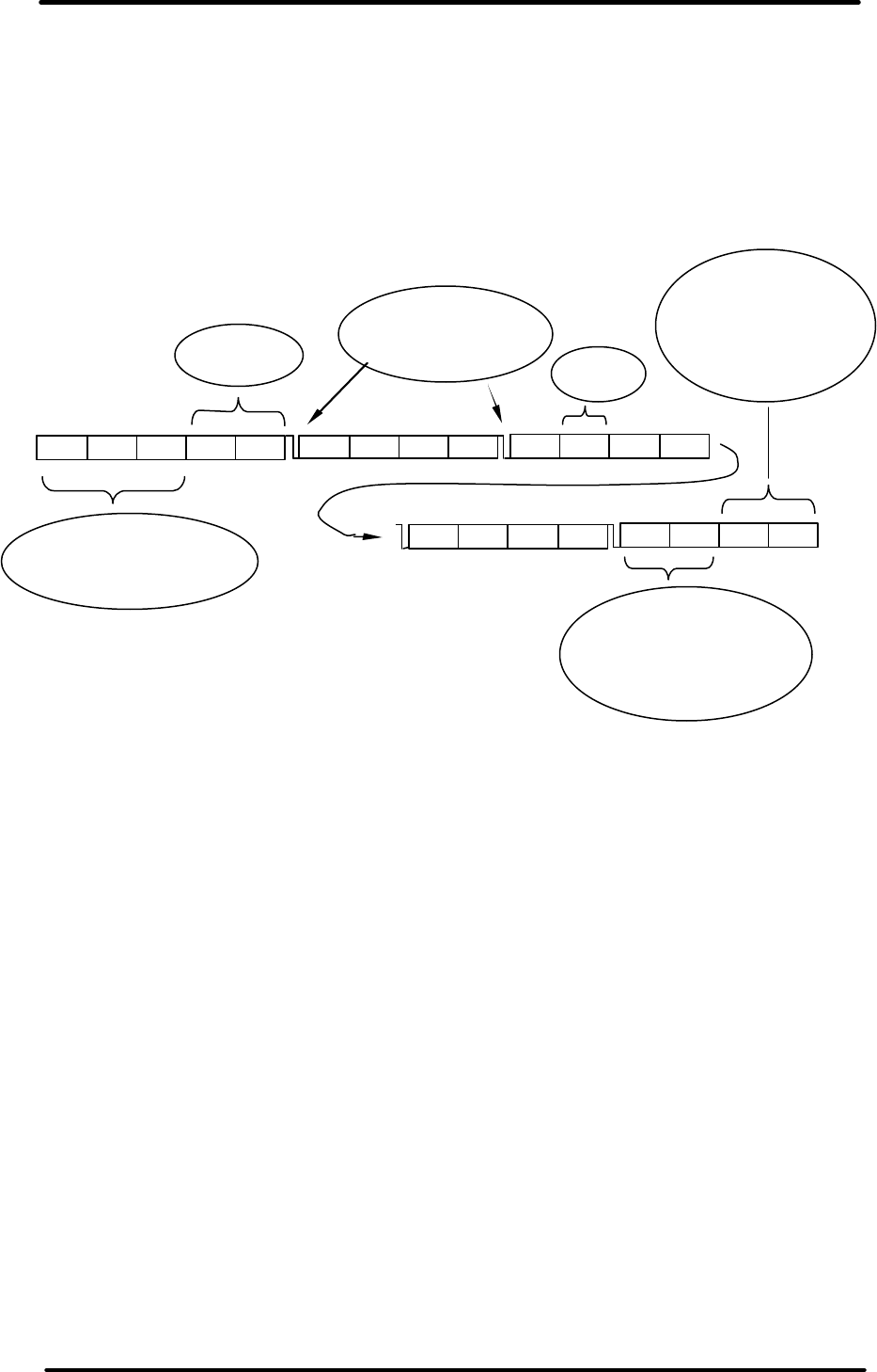
The transmission of data uses Manchester encoding so every bit is transmitted as two bits, first
the bit itself then second the inversion of the bit. This keeps the signal DC balanced and allows
for 100% error checking. The data is clocked LSB first. The diagram below shows a command
packet ..
0xAA 0xAA 0xAA STX0 STX1 Type S.N S/N S/N S/N Data Data Type
Data Data Data Data FCS0 Padding Padding
FCS1
Preamble to condition the
Automatic Gain Circuits
16 bit start
character
Resynchronisation
edges to ensure bit
timing is accurate
Packet
type
Check sum. Fletchers
used because it is fast
- most error checking
done on a per bit basis.
To simplify the
coding packets are
always multiples of 4
bytes plus one 5 byte
block.
REDi TECHNICAL MANUAL
V1.4 5th December 2005 page 50 of 60
6.2 Packet format
Wake Up packet:
Field name # bytes
Field content
Preamble 3 0xAA,0xAA,0xAA
Start character 2 0x72, 0x65
Packet type 1 0x00 - Wake up
Check Sum 2 0x06, 0x22 - Fletcher
Command packet :
Field name # bytes
Field content
Preamble 3 0xAA,0xAA,0xAA
Start character 2
Recipient 5 TSSSS (Logger Type, Serial Number)
Packet type 1 Variable
Data 6 Always 6 bytes in length
Check Sum 2 Fletcher
Very Short Data Packet :
Field name # bytes
Field content
Preamble 3 0xAA,0xAA,0xAA
Start character 2
Logger / Recipient 5 TSSSS (Logger Type, Serial Number)
Packet type 1 0xF0
Data 6 Always 6 bytes in length
Check Sum 2 Fletcher
Short Data Packet :
Field name # bytes
Field content
Preamble 3 0xAA,0xAA,0xAA
Start character 2
Logger / Recipient 5 TSSSS (Logger Type, Serial Number)
Packet type 1 0xF1
Data 32 Always 32 bytes in length
Check Sum 2 Fletcher
REDi TECHNICAL MANUAL
V1.4 5th December 2005 page 51 of 60
Long Data Packet :
Field name # bytes
Field content
Preamble 3 0xAA,0xAA,0xAA
Start character 2
Logger / Recipient 5 TSSSS (Logger Type, Serial Number)
Packet type 1 0xF2
Data 48 Always 48 bytes in length
Sequence 4 Packet number (LSB first)
Check Sum 2 Fletcher
Very Long Data Packet :
Field name # bytes
Field content
Preamble 3 0xAA,0xAA,0xAA
Start character 2
Logger 5 TSSSS (Logger Type, Serial Number)
Packet type 1 0xF3
Data 64 Always 64 bytes in length
Sequence 4 Address where this data has come from (LSB first)
Check Sum 2 Fletcher
Single Byte Reply :
Field name # bytes
Field content
Preamble 3 0xAA,0xAA,0xAA
Start character 2
Logger 5 TSSSS (Logger Type, Serial Number)
Packet type 1 Variable (Ack, Nack etc.)
Check Sum 2 Fletcher

REDi TECHNICAL MANUAL
V1.4 5th December 2005 page 52 of 60
6.3 Specific packet types
REDi to Logger
Name Packet ID
(PType) Packet
Type Recipient Data Description
Wake Up 0x00 Wake up Non specific none Broadcast over and over for 1
second to wake up all loggers.
Ack 0x01 Single Byte
Reply TT,SN,SN,SN,SN none Acknowledgement of correct
reception of a packet.
Resend 0x02 Single Byte
Reply TT,SN,SN,SN,SN none Request for a retransmission of
the last packet.
Who's There ? 0x11 Command 0xFF,0xFF,0xFF,
0xFF,0xFF all blank Request for loggers to identify
themselves.
Don't reply to
"Who's There
?"
0x11 Command TT,SN,SN,SN,SN all blank Tells the specified logger not to
reply to the general "Who's
There ?" packet.
Read Data 0x12 Command TT,SN,SN,SN,SN D[0:2] : address to read
from
D[3:5] : length required
Request for the logger to begin
sending a series of data
packets.
Status Request 0x14 Command TT,SN,SN,SN,SN all blank Request for the loggers status
packet.
How much data
do you have ? 0x15 Command TT,SN,SN,SN,SN all blank Request for the size of data that
the logger holds.
Program
Logger 0x16 Command TT,SN,SN,SN,SN D0 : # of packets that
follow
D1 : flags
D[2:5] : security code
The command to initiate
reprogramming or restarting a
logger. "Logger Program"
packets may follow this.
Check Lease
Count 0x17 Command TT,SN,SN,SN,SN all blank Request for the logger to check
the lease count now.
Logger
Program 0xF2 Long Data TT,SN,SN,SN,SN See section 3.5 on
programming a logger. Data packets containing the
data and locations of a loggers
program.
Logger to REDi
Name Packet ID
(PType) Packet
Type Data Description
Ack 0x01 Single Byte
Reply none Acknowledgement of a correctly received
packet.
Nack 0x03 Single Byte
Reply none The packet was received but was not or cannot
be processed. [no longer used]
Bad Password 0x04 Single Byte
Reply none Reply when a "Program Logger" packet was
received and the logger required a password
and the password was incorrect.
Lease Expired 0x05 Single Byte
Reply none Reply when a "Program Logger" packet was
received but the logger's lease had expired.
Data Request
Reply 0xF3 Very Long
Data Packet 64 bytes of logger data A block of data read out of the logger's
EEPROM.
Data Size
Reply 0xF0 Very Short
Data Packet D[0:2] : data length
D[3:5] : start address Reply to the "How much data do you have ?"
packet.
Status Reply 0x14 Short Data
Packet D[0:1] : Implant f/w
D[2:3] : Logger f/w
D4 : Case type
D[5:22] : Status packet
from host logger
D[23:end] : padding
Reply to a Status Request packet.
All multi byte quantities have MSB at the highest address.
For a more detailed description of each process please refer to the "Wireless Mini Technical Manual -
Implant".

REDi TECHNICAL MANUAL
V1.4 5th December 2005 page 53 of 60
7.0 Hardware

REDi TECHNICAL MANUAL
V1.4 5th December 2005 page 54 of 60
Power supply
The device is powered from 2 AA batteries. In series these will combine to around 2.8V when
fresh and drop to less than 2V when nearly flat. This voltage is boosted with a switching regulator
based around U2 (Microchip TC115) to 3.0V for powering most of the electronics. The converter
has a guaranteed start up voltage of 0.9V.
The boost converter operates from the batteries but in the case when the batteries are either not
present or completely flat U1, an LM317 step down linear regulator, provides the main supply.
This operates from external power and its purpose is essentially to get the unit up and running
and able to charge completely flat batteries.
Z2, a 5V zener diode across the battery, is in place so that if someone runs the REDi off external
power of 6V+ with the batteries removed then the main supply for the electronics is limited to 5V.
The battery voltage is sensed with R12 & R13. This measurement is used to determine if the
battery is getting low as well as to monitor charging progress.
R2 and Z1 are used to monitor the external voltage and provide a digital signal showing if
external power is applied. This line is also used as an interrupt to wake the device if sleeping.
External power is nominally 6.0V but can be as low as 4.5V. More than 6.0V will still charge the
batteries but will create a lot of heat which should be avoided.
The batteries are charged with a linear current regulator. The current through and hence the
voltage drop across R3,4 & 5 keeps Q3 in it's linear range. R3 is not installed so 0.6V/1.65Ω =
360mA. More current will start turning Q3 off and less current will turn it on harder. With
CHG_CTRL high this will govern the drive to Q1, the power FET regulating the charge current.
The display has another boost converter which provides 18V for the LCD drivers. This is located
on the LCD board itself.
Note that the display on the REDi draws a significant in-rush current. There is a 1000uF capacitor
across the supply on the RF sub-board which provides this current. If the device is operated with
the RF sub-board removed (as may happen during servicing) then the in-rush current can
collapse the supply rails and put the M16 into a locked up state. The operator must remove and
replace the batteries to recover from this condition.
When powering up U3 (TCM809) holds everything in a reset state until the supply has stabilised.
Memory
There are two memory systems on the REDi. There is one megabyte of serial Flash memory and
two kilobytes of EEPROM memory.
The EEPROM is accessed via an I2C bus and is located at address 0x00. There is also an RTC
chip on the board that operates via I
2C but this uses a separate bus. The EEPROM is used to
contain system variables and the index table for log records. It has a life expectancy of greater
than one million write cycles so is suitable for frequent rewriting.
One of the limitations on the number of log records that can be stored (160 max) is the size of
index table that will fit into 2k. The EEPROM must be increased in size (with a slight firmware
mod) to extend this number if ever required.
When clocking in data via RF this gets accessed at fairly high speed so the pull up resistors are
10k.
The Flash memory is accessed via it's proprietary serial bus. This proprietary bus has three lines,
Clock, Data in and Data out. It has a life expectancy of 100,000 write cycles per page so is used
to contain each instance of a log record.
When clocking in data via RF this gets accessed at fairly high speed so the pull up resistors are
10k.

REDi TECHNICAL MANUAL
V1.4 5th December 2005 page 55 of 60
There are also 240 bytes of RAM in the RTC chip (U8, PCF8583) but this is not currently used.
No variables are stored in the M16 RAM during power down.
Analogue measurement
The REDi uses the internal ADC of the M16 for analogue to digital conversion. For accuracy an
external reference is used. This is U6, REF1004 and acts like a zener diode with a nominal 1.20V
±4mV. To save power this can have it's supply removed using Q6.
Note that this is installed on the REDi main board but if a ThermoCheck is made using the same
main board then these parts should be on the 'personality' board.
The only analogue value that the REDi measures is battery voltage. The M16 has 8 channels
however and there are tracks on the board connecting another ADC channel (AN2) to connector
CON2. This can be used for a receive signal strength indicator (RSSI) if installed at some stage in
the future on the RF board.
Keypad
The key pad is scanned as a matrix. KEY1-4 (PORT0,1-4) are each taken high in turn and for
each iteration KEYINT1-3 (PORT1,5-7) have their levels checked. This is done on a polling basis
and is not interrupt driven. If two keys are pressed then the first in the sequence will be the only
one recognised.
The KEYINT lines can also be set up as interrupts and this mode is used to wake the device from
sleep.
RTC
Time is kept using a real time clock chip (U8, PCF8583). This is communicated with over an I2C
bus. It is the only device on this bus. D6, a schottkey diode, isolates the power supply to this part
so that when the batteries are replaced C20, a 1000uF cap, will keep supplying voltage to this
chip for several minutes.
This chip also has 240 bytes of RAM which is not currently used.
The chip has the ability to trigger an interrupt after a certain period has elapsed or at a certain
time in the future. This connection is wired up to the M16 but is not used in REDi.
Buzzer
The buzzer is based around a module (BZ1, MBE12C-5) that incorporates it's own oscillator. The
M16 simply applies power to this, using Q5, for the length of the required beep.
RS232
The REDi uses U9, a MAX3320, to handle it's RS232 level conversion. This chip has internal
charge pumps which generate ±12 from the +3V supply. It is wired into the UART of the M16 and
serial transfers are handled by the hardware of the M16.
This chip also generates a interrupt (RS_WAKE_UP) which is used to wake the REDi up, if
asleep, as soon as the comms cable is plugged in.
Display
The display is 160x160 bitmap LCD. All circuitry for driving the display itself is on a separate PCB
to the main board and this is mounted behind the LCD glass. On this there is are two NT7701
driver chips, one for driving the rows and one for driving the columns. These are controlled by an
RA8820 LCD drive controller.
The REDi has an 8 bit wide parallel bus which connects via CON4 to the LCD board. There are
also the associated read-not-write, enable, reset and address/data control signals. The 8 data

REDi TECHNICAL MANUAL
V1.4 5th December 2005 page 56 of 60
lines are pulled either high or low through weak resistors and during power up the state of these
lines govern which mode the controller will power up in.
The RA8820 is switched into graphics mode and all characters are produced by the REDi
sending 10x16 bit maps to the controller. Note that the controller is byte orientated so to work with
10 bit wide characters the bitmaps must be rotated left or right depending on which column they
are to be placed.
The LCD requires 19V to operate and this is generated from the system 3.0V by a switching
boost converter (NCP1403) on the LCD board. The NT7701 driver chips require 4 voltage
references and these are produced using a voltage divider chain and emitter follower buffers. The
highest voltage in this chain is 18.5V and is adjusted by changing the values of R6 and R7 (the
feedback around the NCP1403). The contrast is very sensitive to this level. Also any ripple on the
reference voltages shows up as patchy contrast on the display. This is not an ideal way of
generating reference voltages but has been done in order to keep current consumption to a
minimum.
There is one further control signal to the LCD board and this controls a FET that will disconnect
the entire board from the main 3V supply rail. The RA8820 controller can be placed into a sleep
mode but it still draws the best part of 2mA when sleeping. Complete isolation seems the only
way to conserve battery life when the display is not required.
The display has an electroluminescent back-light which requires 120V AC to glow. The inverter
for this is, based around U10, an IMP560, and is mounted on the main board. The intensity of the
back light is directly related to the voltage of this drive. The frequency is not critical as long as it's
high enough not to flicker. The voltage can be adjusted by R41 and has been set as a
compromise between back-light intensity and current consumption.

REDi TECHNICAL MANUAL
V1.4 5th December 2005 page 57 of 60
Code overview
CHARGEN.C
Contains the bitmaps of the characters that get displayed on the REDi display.
The characters are 10 x 16 pixels. This amounts to 160 pixels which get packed into 20 bytes.
The data is packed with the first byte being the 8 right most pixels on the bottom row of the
character, the next byte contains the 2 left most pixels on the bottom row and the 6 right most
pixels of the second to bottom row. This continues so that after 5 bytes the 4 bottom most rows of
the character are completely defined. The pattern then repeats for the rest of the pixels.
To create or modify the font set for REDi
Use the Excel files; "Alphabet Capitol.xls", "Alphabet lowercase.xls", "Syntax up to capitol A.xls",
and "Other syntax.xls".
Edit the field of 1s and blanks to create the desired pattern. Note that the blanks must be truly
blank for the calculations to work - a space character will upset things so use BackSpace or Del
to clear the fields.
When finished export the file as a comma delimited file.
Load this into your favorite editor and cut and paste the relevant rows of comma separated
numbers to the REDi code CHARGEN.C. You'll have to adjust some of the commas but the bulk
of the work is done.
CMDUTILS.C
Command utilities. The functions in this module process the commands that can be sent by the
PC (as defined in section 5 of this manual). This module differs from COMMAND.C in that it does
the actual work for each command and moves the relevant information to or from the RS232
buffers from or to the system memory. At the bottom of this function can be found all the test
routines for production testing.
COMMAND.C
The functions in this module interpret and reply to the commands sent by the PC. Generally for
each command (as defined in section 5 of this manual) a function exists which checks the
incoming packet then calls a corresponding function in CMDUTILS.C and then reports the result
back to the PC.
DRIVERS.C
Contains low level driver functions for: ADC system, Timers, Battery charging, I2C timing, MCU
clock management, beeper.
The system clock is derived from a 10MHz crystal and can be divided down. In the REDi system
it is divided by two for most of the code as this uses less current but runs at full speed when
clocking RF data in or out.
The battery charging algorithm is detailed in the code so won't be duplicated here in the manual.
FLASH.C
These functions handle reading and writing to the one meg serial flash chip. The chip itself is set
up as a banked system of 4096 pages of 264 bytes. For simplicity the last 8 bytes of each page
are not used and pages are treated as 256 bytes long. Originally these functions were set up to
mimic a randomly accessible linear address space. This means that the functions set up a buffer
in M16 RAM which is filled by the relevant page from Flash when a byte is read from Flash. Any
other bytes that are read from or written to Flash residing in that same page are then processed
using the RAM buffer. When bytes from a different page are required the RAM image is written in

REDi TECHNICAL MANUAL
V1.4 5th December 2005 page 58 of 60
entirety to Flash (if there have been writes) then the new page is read from Flash. As with all flash
devices time must be allowed for the memory to sink in after a write before other pages can be
accessed.
In the interest of high speed data transfer, however, the RF code as well as much of the other
code reads and writes pages directly as blocks of 256 bytes. The start of the RS232 Tx buffer is
used for this. To avoid getting out of sync with the 'linear address space' system
BringFlashUpToDate() must be called before directly reading and writing pages from/to the serial
flash. This will ensure that anything that was written to the RAM buffer actually does get updated
to the memory chip and anything that system doesn't believe that old data sitting in the RAM
buffer is current.
This is all a bit messy but works well and was required to get quick and reliable timing for the RF
code while not rewriting lots of the existing code that REDi was built on.
GLCD.C
This module contains the code to draw text and graphics on the LCD. The display has an
effective 'cursor position' which defines where characters are to be put. This will increment as
expected as characters are drawn much like printf(""). The cursor position can be read or
changed with glgetXY() and glgoto(). The home position (0,0) for text or graphics is the top left
hand corner of the display.
Generally the code only needs to call the relevant text or graphic function, which updates an
image of the display stored in M16 RAM, and the changes will be 'blitted' to the display controller
chip when the blitting interrupt next occurs (every 50ms). If, however, the interrupts are disabled,
such as during RF transfers, then the code must call the relevant text or graphic function then
explicitly call a function called glcd_send_bitmap() to get the changes to appear on the LCD. If
time is an issue then another function called glcd_update_slice() can be used which only blits a
specific area of the display. The remaining area remains unchanged.
I2C.C
This module contains code to bit-bash either of the two I2C busses on the main board (one for 2k
EEPROM and one for the RTC). The main functions of interest are I2CRead() and I2CWrite()
which linearise the address paging and handle timing considerations for writing.
INT.C
This module contains the system interrupts. These include RS232 in, RS232 out, system tick,
wake up on key press, wake up from external power application, wake up on RS232 connection,
RTC interrupt (not used), and Watch Dog (normally disabled).
The system tick occurs every 50ms and is used for beep termination, keyboard scanning and
display blitting. After 20 systems ticks (one second) the trickle charger, back light timer, and
comms-mode symbol are checked. After 1200 systems ticks (one minute) the auto-off timer and
battery charge timers are checked.
KEYBOARD.C
This module contains routines for reading the keyboard. In the function ScanKeyboard() the
keyboard is scanned as a matrix and the global variables gKeymap[n] are set up which contain
the state of the keypad. This function also returns a variable denoting the current key that is
pressed (or the first one detected if more than one key is pressed). This function is usually called
every 50ms by the system interrupt and used to set up the global variable uKey which can be
used by other code ie. in the function ProcessKeys() in PROCESS.C.
The keyboard can be used to trigger interrupts but this is only done for waking from sleep.
There is also a function called SetBeeper() which can be used to turn the beeper on. The beeper
will then continue beeping until an interrupt turns it off.
MAIN.C
This is highest level function. It contains the "main" function which continuously loops until
something happens. Note that some of the processing such as servicing RS232 requests or

REDi TECHNICAL MANUAL
V1.4 5th December 2005 page 59 of 60
displaying lists of data can take quite a while and this is time the that main loop is not looping.
Interrupts keep running but this is not a real time operating system. Note also that during RF
transfers the interrupts are disabled and the code can spend several tens of seconds away from
this loop.
It also contains code for setting up registers, ports etc. immediately after power up as well as
parking things prior to going to sleep.
MEMORY.C
This module contains the functions MemoryWrite() and MemoryRead(). These are high level
functions that are used to abstract other code from the physical details of the memory. They are
called with the memory Type, Address and run length for either reading or writing. The Type is
defined in Section 4.3 Memory Reference of this manual. The code takes care of any bank
switching or timing that is required for the specific memory type. These functions are only
sometimes used by the REDi code and at other times the memory is directly accessed in order to
cut out overhead.
PROCESS.C
Process.c contains functions for processing some of the low level system fetaures. These include
restarting the Auto-off timer, entering of Safe mode (hold left and down arrow down during power
up), update system variables after changes after RS232 communication eg. flushing all log
records, action any key presses, handle shutting of the REDi, checks the integrity of the serial
number etc. after power up (this has a CRC associated with it) to catch any flash corruption if it
happens, the display of the comms icon during RS232 transfers, default configuration (in case of
initial set-up or set-up corruption).
Safe mode is used for diagnostics and will get the unit up and running with no display and
adjusted IRQ priorities. The unit can then be interrogated via. RS232.
RF.C
This code controls all RF transfers. The two functions for actually transmitting and receiving a
packet of data are written in assembler. The data is bit bashed and has specific timing. Do not
touch these unless absolutely necessary. The function ListenForWakeUpReplies() also has
specific timing and if modified should be treated with caution. Other functions include the analysis
of what loggers are out there, reading the entire data buffer of each logger in and storing it to
flash, and reprogramming loggers. Most of the functions are executed with interrupts turned off so
the display will not be updated unless specifically told to and RS232 response, auto off etc. will be
momentarily suspended.
When the data is stored there is a structure called LoggerHead and another structure called
PreLoggerHead which are used heavily. LoggerHead contains format descriptors and pointers for
all the various system variables that are found in Escorts loggers (eg. LogStartTime,
SecurityCode etc.) There should be a LoggerHead structure defined for each type of logger that
the REDi can recognise and this will tell it how to interpret the data that is extracted from that
logger. Note that all logger data is passed to the PC verbatim - interpretation of the data is only
for display purposes on the REDi screen. PreLoggerHead is a formatted summary of the most
common information from each logger and there is an instance of this structure stored with each
log record in Flash memory. Reading this summary avoids the need to process the data each
time the user wants to review a specific log record.
RS232.C
This module contains the highest level of code for processing RS232 packets. It also includes the
low level code for changing the RS232 baud rate however as of Oct. '05 the baud rate is fixed at
9600.
The RS232 interface is handled by hardware. The clocking in of bits is performed by M16
hardware and the clocking in of bytes is performed in INT.C. This module only gets called once
complete packets have arrived.
For clocking out of packets the individual bits are clocked by M16 hardware and each byte is
loaded by a function RS232Transmit() in conjunction with an interrupt.

REDi TECHNICAL MANUAL
V1.4 5th December 2005 page 60 of 60
TIME.C
Contains functions for manipulating time and date.
USERIF.C
This is a very big module and, in conjunction with Menus.h, contains the user interface.
It contains all the code for drawing menus. An example of the menu structure and how to add a
menu is included at the end of this section.
ui_ProcessMenu() contains all the code for scrolling the menu bar up and down and selecting a
menu item.
SetUpMenuEleven() creates the menu, including a brief summary of the data, for selecting a log
record to display (All or Recent). This reads the PreLoggerHead (a formatted summary of the log
record) from Flash memory and transfers to a RAM structure to be used in other parts of the
code.
ui_GenerateStatisticsMenu() creates the menu which actually displays the summary information.
This uses the PreLoggerHead structure that was filled in by SetUpMenuEleven().
SetUpMenuFourteen() creates and manipulates the menu for viewing out of spec readings.
The module contains utility functions for formatting a serial number for display, formatting a
product code for display, decoding the program state of a logger.
There is a function for calculating the time out of spec. This is done by creating a cumulative
histogram of the logged readings then counting the number that fall above or below the defined
limits. The histogram is retained as a static array and can be used for analyzing the data further if
this is ever required. The array is 256 bytes long for 8 bit samples. If 10 bit samples are to be
analyzed then this array will need to be increased to 1k in size.
There are functions for displaying the start up 'splash screen'. Switching into test mode upon start
up. Displaying the battery icon & RTC. Fetching the RTC from the PCF8583 chip and formatting it
for display.
There is a function to allow a security password to be entered immediately after power up and
block access to the REDi if incorrect.
The module also contains the "REDi" image as a hard coded array. This was produced using an
Excel spread-sheet in that same way as the characters were.
It also contains the LoggerHead definitions which define format descriptors and pointers which tell
the REDi how to interpret the data from specific types of loggers.
UTILS.C
Contains useful utility functions such as 'BCD to Char' conversion 'Integer to ASCII' etc.
The menu structure