Essence Security ES800UT Universal transmitter User Manual We R System
Essence Security International ltd. Universal transmitter We R System
Contents
- 1. User_Guide_part1
- 2. User_Guide_part2
- 3. User_Guide_part3
- 4. User_Guide_part7
- 5. User_Guide_part8
User_Guide_part1
We.R™ System
User Guide
ESUG05022
Version 3.3
December 2013

Legal Notice
Usage of this document, and all information (including product information) provided within, are subject to the following terms and conditions,
and all applicable laws. If you do not agree with these terms, please do not access or use the remainder of this document.
This document contains highly confidential information, which is proprietary to Essence Security International (E.S.I.) Ltd. and/or its affiliates
(hereafter, "Essence"). No part of this document's contents may be used, copied, disclosed or conveyed to any third party in any manner
whatsoever without prior written permission from Essence.
The information included in this document is intended for your knowledge and for negotiation purposes only. Essence makes no implicit
representations or warranties with respect to such information.
The information included in this document is subject to change without notice. Any decision to rely on the information contained herein shall be
at your sole responsibility, and Essence will not accept any liability for your decision to use any information or for any damages resulting
therefrom.
Certain laws do not allow limitations on implied warranties or the exclusion or limitation of certain damages. If these laws apply to you, some or
all of the above disclaimers, exclusions, or limitations may not apply to you.
By using the information contained herein, you agree that the laws of the state of Israel, without regard to principles of conflict of laws, will
govern any dispute of any sort that might arise between you and Essence regarding the information contained herein, and any such dispute
shall be settled exclusively in the competent courts of Tel Aviv-Jaffa, Israel.
All registered or unregistered trademarks, product names, logos and other service marks mentioned within this document are the property of
Essence, or their respective owners. Nothing contained herein shall be construed as conferring by implication, estoppels, or otherwise any
license or right, either express or implied, under any patent or trademark of Essence or any third party. No use of any trademark may be made
without the prior written authorization of Essence.
This document and all of its contents are protected intellectual property of Essence. Any copying, reprinting, reuse, reproduction, adaptation,
distribution or translation without the prior written permission of Essence is prohibited.
Please check your End User License Agreement (EULA) for terms and Conditions.
© 2012 All rights reserved to Essence Security International (E.S.I.) Ltd.
Certification Notice
NOTE: This equipment has been tested and found to comply with the limits for a Class B digital device, pursuant to part 15 of the FCC
Rules. These limits are designed to provide reasonable protection against harmful interference in a residential installation. This equipment
generates uses and can radiate radio frequency energy and, if not installed and used in accordance with the instructions, may cause harmful
interference to radio communications. However, there is no guarantee that interference will not occur in a particular installation. If this
equipment does cause harmful interference to radio or television reception, which can be determined by turning the equipment off and on, the
user is encouraged to try to correct the interference by one or more of the following measures:
- Reorient or relocate the receiving antenna.
- Increase the separation between the equipment and receiver.
- Connect the equipment into an outlet on a circuit different from that to which the receiver is connected.
- Consult the dealer or an experienced radio/TV technician for help.
Changes or modifications to this equipment not expressly approved by the party responsible for compliance (Essence Security International
(E.S.I.) Ltd.) could void the user’s authority to operate the equipment.
WARNING! To comply with FCC and IC RF exposure compliance requirements, the device should be located at a distance of at least 20 cm
from all persons during normal operation. The antennas used for this product must not be co-located or operated in conjunction with any
other antenna or transmitter.
Le dispositif doit être placé à une distance d'au moins 20 cm à partir de toutes les personnes au cours de son fonctionnement normal. Les
antennes utilisées pour ce produit ne doivent pas être situés ou exploités conjointement avec une autre antenne ou transmetteur.
For more information, please contact: Essence Security International (E.S.I.) Ltd.
12 Abba Eban Avenue, Ackerstein Towers Bldg. D
Herzliya Pituach, 4612001 Israel
www.essence-grp.com
Tel: +972-73-2447777
Fax: +972-9-7729962
This device complies with FCC Rules Part 15 and with Industry Canada license-exempt RSS standard(s). Operation is subject to the
following two conditions:
(1) This device may not cause harmful interference, and
(2) This device must accept any interference received, including interference that may cause undesired operation
Le présent appareil est conforme aux CNR d'Industrie Canada applicables aux appareils radio exempts de licence. L'exploitation est
autorisée aux deux conditions suivantes:
(1) l'appareil ne doit pas produire de brouillage, et
(2) l'utilisateur de l'appareil doit accepter tout brouillage radioélectrique subi, même si le brouillage est susceptible d'en compromettre le
fonctionnement.
How to Use this Guide
We.R™ System User Guide
3
How to Use this Guide
The backbone of this guide is the We.R™ installation procedure – following an introduction to
the system concept, the guide takes you through the steps of identifying the system
components and their functions, preparations, and installation of the system components
(hardware and software) in the recommended sequence ensuring smooth buildup of your
We.R™ system. This is the largest section of this guide and includes basic understanding of the
setup and operation of both the components and the whole system.
The daily usage of the system (system administration) is provided in the following section, while
maintenance – on the next. Other required information is also provided thereafter.
Complementary information covering different aspects of background knowledge related to the
We.R™ are provided in the form of appendixes at the end of this guide as well.

How to Use this Guide
4
We.R™ System User Guide
This page was intentionally left blank

Table of Contents
We.R™ System User Guide
5
Table of Contents
How to Use this Guide ........................................................................................................ 3
Table of Contents ............................................................................................................... 5
1. Introduction .............................................................................................................. 13
1.1. Foreword .............................................................................................................. 13
1.2. General Guidelines ............................................................................................... 14
1.3. Content of the Standard Kit Box ........................................................................... 14
1.4. Other Available Devices ........................................................................................ 18
2. System Theory ......................................................................................................... 21
2.1. System Topology ................................................................................................. 21
2.2. The Complete System Overview ........................................................................... 22
2.3. Unique Technologies Incorporated ....................................................................... 23
2.3.1. Enhanced Controlled Open Protocol .................................................... 23
2.3.2. We.R™ RF Technology ........................................................................ 23
2.3.2.1. Radio Interface Information........................................................ 23
2.3.3. Remote Software Update .................................................................... 24
2.3.4. We.R™ Cloud Services ........................................................................ 24
2.3.4.1. We.R™ Web Server ................................................................... 26
2.3.4.2. Information Consumption Services ............................................ 26
2.3.4.3. We.R™ Media Services .............................................................. 26
2.3.4.4. We.R™ SMS Services ................................................................ 26
2.3.4.5. We.R™ Database ...................................................................... 27
2.3.4.6. We.R™ Analysis Service ............................................................ 27
3. Installation of the We.R™ System ............................................................................... 29
3.2. The Central Control Unit – ES8000CP .................................................................. 31
3.2.1. The Central Control Unit Function ........................................................ 32
3.2.2. Installing the Central Control Unit ......................................................... 32
3.2.2.1. CCU Positioning Recommendations .......................................... 33
3.2.3. Activating the Central Control Unit ....................................................... 36
3.2.3.1. Manual Access Point Name Data Registration ........................... 43

Table of Contents
6
We.R™ System User Guide
3.3. The We.R™ Web Application ................................................................................. 45
3.3.1. The Web Application Function ............................................................. 45
3.3.2. Activating the Web Application ............................................................ 46
3.3.2.1. Prerequisites ............................................................................. 46
3.3.3. The Web Application Display Structure ................................................ 47
3.3.4. The Tool Bar ........................................................................................ 48
3.3.5. The Status/Activation Bar .................................................................... 51
3.3.6. The Data Window ................................................................................ 52
3.3.6.1. The Dashboard Page ................................................................ 52
3.3.6.2. The Devices Page ..................................................................... 56
3.3.6.3. The History Page ...................................................................... 58
3.3.6.4. The Users Page ........................................................................ 60
3.3.6.5. The Smart Home and Scenarios Pages ..................................... 61
3.3.6.6. Other Pages .............................................................................. 62
3.4. The We.R™ Mobile Application.............................................................................. 62
3.4.1. Downloading and Installing the We.R™ Mobile Application ................... 63
3.4.2. Limitations of the We.R™ Mobile Application ........................................ 65
3.4.3. Using the Mobile Application ................................................................ 66
3.4.3.1. The User Code Screen .............................................................. 66
3.4.3.2. The Home Status (Main) Screen ................................................ 67
3.5. The Remote Control Unit (KF) – ES800KF ............................................................. 82
3.5.1. The Remote Control Unit (KF) Function ................................................ 82
3.5.2. Installing and Activating the Remote Control Unit (KF) .......................... 83
3.5.3. The Remote Control Unit (KF) Status Reporting ................................... 87
3.6. The Motion Indoor Photo Detector (IPD) – ES800IPD ............................................ 88
3.6.1. The Motion Indoor Photo Detector Function ......................................... 88
3.6.1.1. The Camera Modes of Operation .............................................. 89
3.6.2. Installing the Camera ........................................................................... 90
3.6.2.1. Camera Positioning Recommendations ..................................... 91
3.6.2.2. Installing with Screws ................................................................ 92
3.6.2.3. Installing with Pre-attached Double-side Tape ........................... 93
3.6.2.4. Dismounting the Camera ........................................................... 93

Table of Contents
We.R™ System User Guide
7
3.6.3. Adding the Camera to the We.R™ System ........................................... 94
3.6.4. The Camera Operational Modes .......................................................... 99
3.6.4.1. Walk Test Mode ...................................................................... 100
3.6.4.2. Normal Operation Mode .......................................................... 100
3.7. The Motion Detector (PIR) – ES800PIR ............................................................... 100
3.7.1. The Motion Detector Function ............................................................ 101
3.7.2. Installing the Motion Detector............................................................. 102
3.7.2.1. Motion Detector Positioning Recommendations ...................... 103
3.7.2.2. Installing with Screws .............................................................. 105
3.7.2.3. Installing with Pre-attached Double-side Tape ......................... 105
3.7.2.4. Dismounting the Motion Detector ............................................ 105
3.7.3. Adding the Motion Detector to the We.R™ System ............................. 106
3.7.4. The Motion Detector Operational Modes ............................................ 111
3.7.4.1. The Walk Test Mode ............................................................... 111
3.7.4.2. The Normal Operation Mode ................................................... 112
3.8. The Door/Window Magnetic Sensor (MGL) – ES800MGL ................................... 112
3.8.1. The Magnetic Sensor Function .......................................................... 113
3.8.2. Installing the Magnetic Sensor ........................................................... 113
3.8.2.1. Magnetic Sensor Positioning Recommendations ..................... 114
3.8.2.2. Installing the Transmitter Unit with Screws ............................... 116
3.8.2.4. Dismounting the Magnetic Sensor ........................................... 117
3.8.3. Adding the Magnetic Sensor to the We.R™ System ........................... 118
3.8.4. Testing the Magnetic Sensor ............................................................. 123
3.9. The Indoor Siren (SRN) – ES800SRN .................................................................. 123
3.9.1. The Indoor Siren Function .................................................................. 124
3.9.2. Installing the Siren.............................................................................. 125
3.9.2.1. Siren Positioning Recommendations ....................................... 125
3.9.2.2. Installing with Screws .............................................................. 127
3.9.2.3. Installing with Pre-attached Double-side Tape ......................... 127
3.9.2.4. Dismounting the Indoor Siren .................................................. 127
3.9.3. Adding the Indoor Siren to the We.R™ System ................................... 128
3.10. The Wireless Access Control Tag Reader (TR5) – ES800TR5 .............................. 132

Table of Contents
8
We.R™ System User Guide
3.10.1. The Tag Reader Function .................................................................. 133
3.10.2. Installing the Tag Reader ................................................................... 134
3.10.2.1. Tag Reader Positioning Recommendations ............................. 135
3.10.2.2. Installing with Screws .............................................................. 136
3.10.2.3. Installing with Pre-attached Double-side Tape ......................... 136
3.10.2.4. Dismounting the Tag Reader ................................................... 136
3.10.3. Adding the Tag Reader to the We.R™ System.................................... 137
3.10.4. Adding Tags to the We.R™ System .................................................... 142
3.11. The Flood Detector (FL) – ES800FL .................................................................... 146
3.11.1. The Flood Detector Function .............................................................. 147
3.11.2. Installing the Flood Detector .............................................................. 148
3.11.2.1. Flood Detector Positioning Recommendations ........................ 149
3.11.2.2. Installing the Flood Detector Transmitter Unit with Screws ....... 149
3.11.2.3. Installing the Flood Detector Sensor Unit with Screws ............. 150
3.11.2.4. Installing Transmitter Unit with Pre-attached Double-side Tape 150
3.11.2.5. Installing Sensor Unit with Pre-attached Double-side Tape ...... 151
3.11.2.6. Dismounting the Flood Detector .............................................. 151
3.11.3. Adding the Flood Detector to the We.R™ System ............................... 152
3.12. The Smoke Detector (SK2) – ES800SK2............................................................. 155
3.12.1. Product Function ............................................................................... 157
3.12.2. Installing the Smoke Detector ............................................................ 158
3.12.2.1. Smoke Detector Positioning Recommendations ...................... 158
3.12.2.2. Installing Smoke Detector with Screws .................................... 162
3.12.2.3. Cleaning the Smoke Detector .................................................. 164
3.12.3. Adding the Smoke Detector to the We.R™ System ............................ 165
3.12.3.1. Testing the Smoke Detector .................................................... 170
3.13. The Universal Transmitter (UT) – ES800UT .......................................................... 171
3.13.1. The Universal Transmitter Function .................................................... 172
3.13.2. Installing the Universal Transmitter ..................................................... 172
3.13.2.1. Universal Transmitter Positioning Recommendations ............... 173
3.13.2.2. Installing with Screws .............................................................. 173
3.13.2.3. Installing with Pre-attached Double-side Tape ......................... 174

Table of Contents
We.R™ System User Guide
9
3.13.2.4. Dismounting the Universal Transmitter ..................................... 174
3.13.3. Adding the Universal Transmitter to the We.R™ System ..................... 175
3.14. The We.R™ Z-Wave® Controller (ZWD) – ES800ZWD .......................................... 180
3.14.1. The Z-Wave® Concept....................................................................... 180
3.14.2. Essence Z-Wave® Controller .............................................................. 181
3.14.2.1. The We.R™ Z-Wave® Controller Generic Device Classes ......... 182
3.14.3. Installing the Z-Wave® Controller ........................................................ 183
3.14.3.1. Verification .............................................................................. 185
3.14.4. Activating the Z-Wave® Controller ...................................................... 185
3.14.4.1. Adding a New Z-Wave® Device ............................................... 185
3.14.4.2. Removing a Connected Z-Wave® Device ................................ 188
3.14.4.3. Controlling a Z-Wave® Device via the We.R™ System .............. 190
3.15. System Support Capabilities ............................................................................... 194
4. Administration of the We.R™ System........................................................................ 197
4.1.1. Types of Security Arming Modes ....................................................... 198
4.1.1.1. Full Arm .................................................................................. 198
4.1.1.2. Day Arm .................................................................................. 199
4.1.1.3. Night Arm ............................................................................... 199
4.1.1.4. Disarm .................................................................................... 200
4.1.1.5. Arming/Disarming with We.R™ System Devices ....................... 200
4.1.1.6. Force Arming .......................................................................... 201
4.2. Handling Alarms ................................................................................................. 201
4.2.1. Security Alarms ................................................................................. 202
4.2.2. Safety Alarms .................................................................................... 206
4.2.3. Panic Alarms ..................................................................................... 208
4.3. Monitoring the Premises ..................................................................................... 213
4.3.1. Monitoring with the We.R™ Web Application ...................................... 214
4.3.2. Monitoring with the We.R™ Mobile Application ................................... 215
4.4. Managing Users ................................................................................................. 218
4.4.1. Profiling Users ................................................................................... 218
4.4.2. Adding Users ..................................................................................... 219
4.4.3. Removing Users ................................................................................ 221

Table of Contents
10
We.R™ System User Guide
4.4.4. Editing Users ..................................................................................... 221
4.5. Managing Devices .............................................................................................. 222
4.5.1. Adding New Devices ......................................................................... 222
4.5.2. Removing Devices ............................................................................. 224
4.5.3. Editing Devices’ Properties ................................................................ 225
4.5.4. Advanced Configurations of the We.R™ Devices ................................ 226
4.5.4.1. Entry/Exit ................................................................................ 226
4.5.4.2. Devices Allowing Walk-Through .............................................. 227
4.5.4.3. Chime ..................................................................................... 228
5. Maintenance of the We.R™ System .......................................................................... 231
5.1. Replacing Batteries ............................................................................................ 231
5.1.1. Replacing the Central Control Unit Backup Battery ............................ 231
5.1.1.1. Removing the Old Backup Battery .......................................... 231
5.1.1.2. Installing a New Battery ........................................................... 233
5.1.2. Replacing the Camera (IPD) Batteries ................................................ 234
5.1.2.1. Removing the Old Batteries ..................................................... 234
5.1.2.2. Installing New Batteries ........................................................... 235
5.1.3. Replacing the Motion Detector (PIR) Batteries .................................... 236
5.1.4. Replacing the Magnetic Sensor (MGL) Battery ................................... 238
5.1.4.1. Removing the Old Batteries ..................................................... 238
5.1.4.2. Removing the Old Battery ....................................................... 239
5.1.4.3. Installing a New Battery ........................................................... 239
5.1.5. Replacing the Indoor Siren (SRN) Batteries ........................................ 240
5.1.6. Replacing the Remote Control Unit (KF) Battery ................................. 243
5.1.6.1. Removing the Old Battery ....................................................... 244
5.1.6.2. Installing a New battery ........................................................... 244
5.1.7. Replacing the Tag Reader (TR5) Batteries .......................................... 245
5.1.8. Replacing the Flood Detector (FL) Battery .......................................... 247
5.1.9. Replacing the Smoke Detector (SK2) Batteries .................................. 249
5.1.9.1. Dismounting the Smoke Detector ............................................ 249
5.1.9.2. Removing the Old Batteries ..................................................... 250
5.1.9.3. Installing New Batteries ........................................................... 251

Table of Contents
We.R™ System User Guide
11
5.1.10. Replacing the Universal Transmitter (UT) Battery ................................ 251
5.1.10.1. Dismounting the Universal Transmitter ..................................... 252
5.2. Cleaning the System Devices.............................................................................. 254
6. Security Aspects ..................................................................................................... 255
6.1. Secured Communication between User and Application Server .......................... 255
6.2. Communication Security between CCU and Application Server .......................... 255
6.3. Communication Security between CCU and sensors .......................................... 255
Appendix A Terms, Abbreviations and Acronyms ............................................... 257
Appendix B End User License Agreement (EULA) ............................................... 267
Appendix C Technical Specifications .................................................................. 279
Central Control Unit (CCU) – ES8000CP ..................................................................... 279
Motion Indoor Photo Detector (IPD) – ES800IPD ......................................................... 280
Motion Detector (PIR) – ES800PIR .............................................................................. 281
Door/Window Magnetic Sensor (MGL) – ES800MGL ................................................... 283
Indoor Siren (SRN) – ES800SRN ................................................................................. 284
Remote Control Unit (KF) – ES800KF .......................................................................... 285
Wireless Access Control Tag Reader (TR5) – ES800TR5 ............................................. 286
Flood Detector (FL) – ES800FL ................................................................................... 287
Smoke Detector (SK2) – ES800SK2 ............................................................................ 288
Universal Transmitter (UT) – ES800UT ......................................................................... 289
Z-Wave® Controller (ZWD) – ES800ZWD ..................................................................... 291
Appendix D Port Checking ................................................................................ 293
Appendix E Enable Telnet Program in Windows 7 and 8 ..................................... 295
Appendix F Screws and Dowels ........................................................................ 297
Appendix G Pairing and Bonding ....................................................................... 299
Motivation ................................................................................................................... 299
Implementation ........................................................................................................... 299
Appendix H Owner’s Records ........................................................................... 301

Table of Contents
12
We.R™ System User Guide
This page was intentionally left blank

Introduction
We.R™ System User Guide
13
1. Introduction
Welcome to the We.R™ Smart Home System User Guide.
The We.R™ Smart Home system enables consumers manage different aspects of their homes
such as security, safety, home automation and energy savings from anywhere and at any time
using their PCs or smart device applications.
The We.R™ system is a self-monitoring DIY solution based on the most advanced wireless
technologies that include cloud services, and remote management and automation
applications from any device, coupled with unique hardware design for consumers’ homes.
1.1. Foreword
To begin utilizing the system, it is required to link onto the We.R™ Web Application (link
address is provided by the seller or the Security Service Provider) and register as a User.
The Mobile Application, for both Apple® iPhone® (iOS) and Android™
users, may be downloaded later from the following QR-code link:
(or search within Apple’s App Store or Google’s Play for We.R™)
The installation program of these applications guides the Users through
all phases of the identification, installation and registration process.
Once the system is accessed, the registered Users may begin enjoying
its many benefits, including:
Get real time alerts in case of unpermitted access to the premises.
Protect valuables and personal belongings, based on unique living habits.
Monitor entrance and exit time of residence staff, such as the cleaner, babysitter, etc.
Be informed when kids are back from school etc.
Keep kids away from the medicine cabinet, basement and other high-risk zones.
Watch over children when they are out of sight.
Care for elderly parents when needed.
Watch for pet left alone at home.
Connect, control and manage the premises, anywhere and anytime.
Remain up-to-date with all new system and components software.

Introduction
14
We.R™ System User Guide
1.2. General Guidelines
Following are some general guidelines for the installation and day-by-day usage of the We.R™
system:
Batteries should not be inserted into any of the system devices until a specific step in
the installation process is reached.
Proper order of installing the batteries ensures that the various components of the
system are integrated into the system in the correct sequence.
The Central Control Unit (CCU) must be positioned at least 1 meter away from other
We.R™ system components for proper operation.
There are two types of components:
The Central Control Unit, and
The peripheral devices (devices triggering alarms or set Home Automation).
The peripherals are referred to, within this guide, as devices.
Keep the system components away from wet, hot or humid environments.
Temperature ranges:
Devices with Alkaline batteries:
Storage Ambient Temperature range: -20°C – 50°C
Operating Ambient Temperature range: 0°C – 50°C
Devices with batteries:
Storage Ambient Temperature range: -20°C – 60°C
Operating Ambient Temperature range: -5°C – 50°C
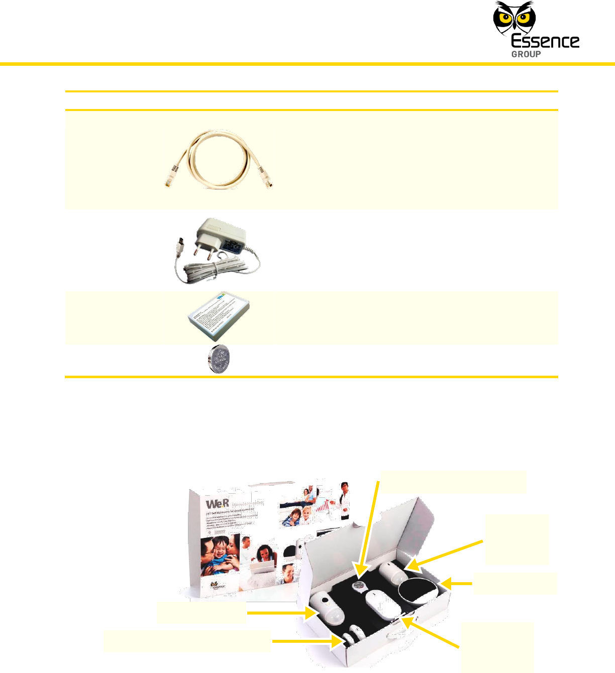
1.3. Content of the Standard Kit Box
The following Table 1 details the content of the Kit Box.
Note: Following description of the Kit Box content refers to the standard kit.
Other combinations of components included in the kit are possible too.
Introduction
We.R™ System User Guide
15
Product
Description
Central Control
Unit (CCU) –
Essence
ES8000CP
The We.R™ Central Control Unit. Sometimes referred
to as Control Panel (CP). Manage and communicate
with system peripherals and the Cloud/Servers which
provide the data to the different user applications.
Generates notifications and source data streaming.
It features:
Users’ remote access for control and
management via Apple’s iOS and Google’s
Android™ based smartphones/tablets and web
application software.
Optional 3G (850/900/1800/1900MHz)
modem.
Automatic APN setting.
Streaming of data to designated devices
(smartphone, PC, etc.).
Supports large variety of peripherals and up to
32 Users (including 2 Master Users).
Long term battery backup.
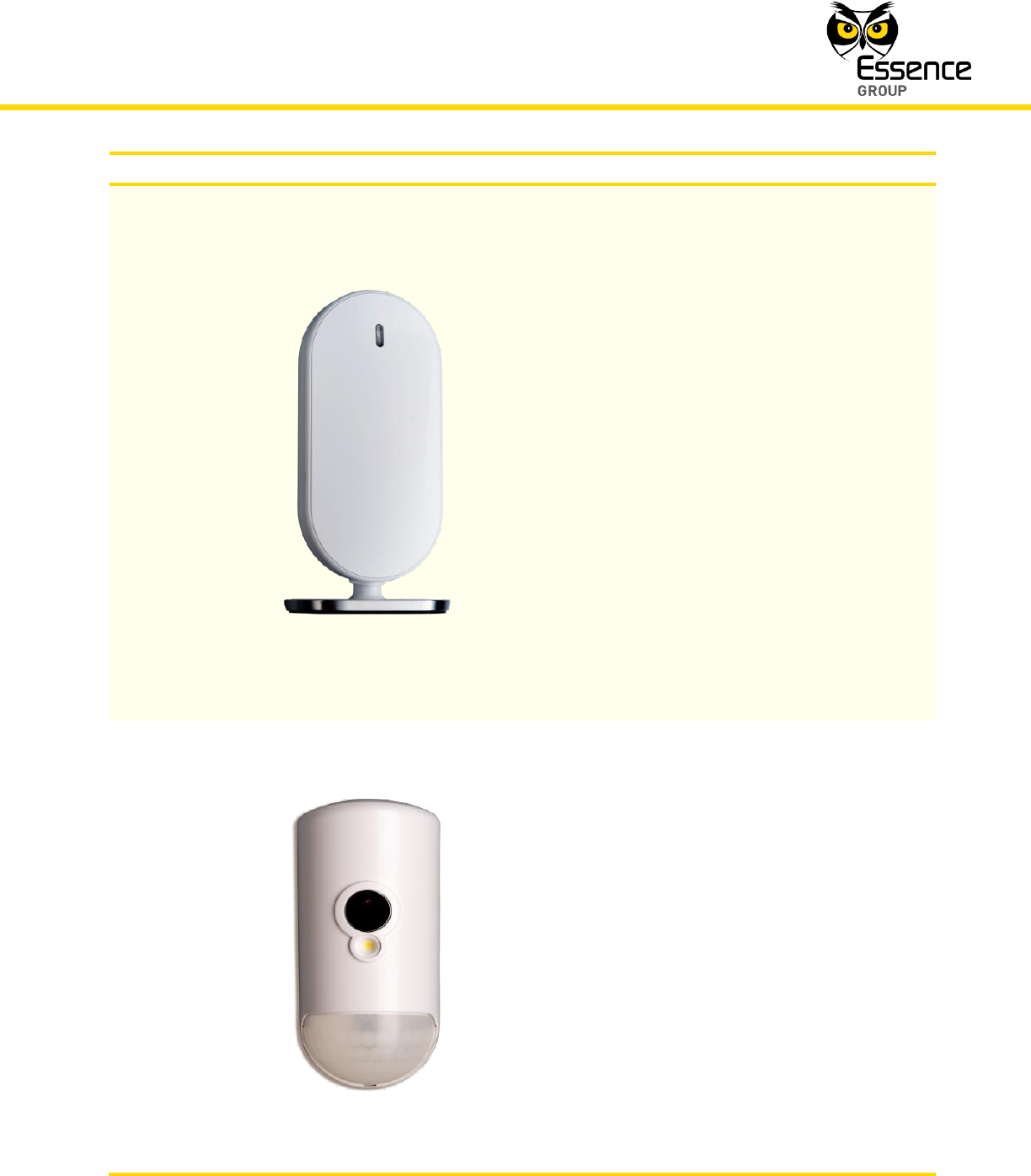
Motion Indoor
Photo Detector
(IPD) – Essence
ES800IPD
A peripheral device combining Passive Infra-Red (PIR)
motion detector along with image capturing camera.
Referred to as the system’s Camera. It features:
Security/Comfort motion detected images
streaming to smartphone/web applications.
Compress/Encrypt data with Essence’s
proprietary ECOP protocol.
Relays stream to the We.R™ servers, via the
Cloud for distribution to designated devices
(smartphone, PC, etc.).
Multi-zone spherical lens for wide coverage
(120o horizontal, 105o vertical).
Sealed optics, immune to light, insects, and
(optional) pets, for reduced false alarms.
Walk-through test mode.
Introduction
16
We.R™ System User Guide
Product
Description
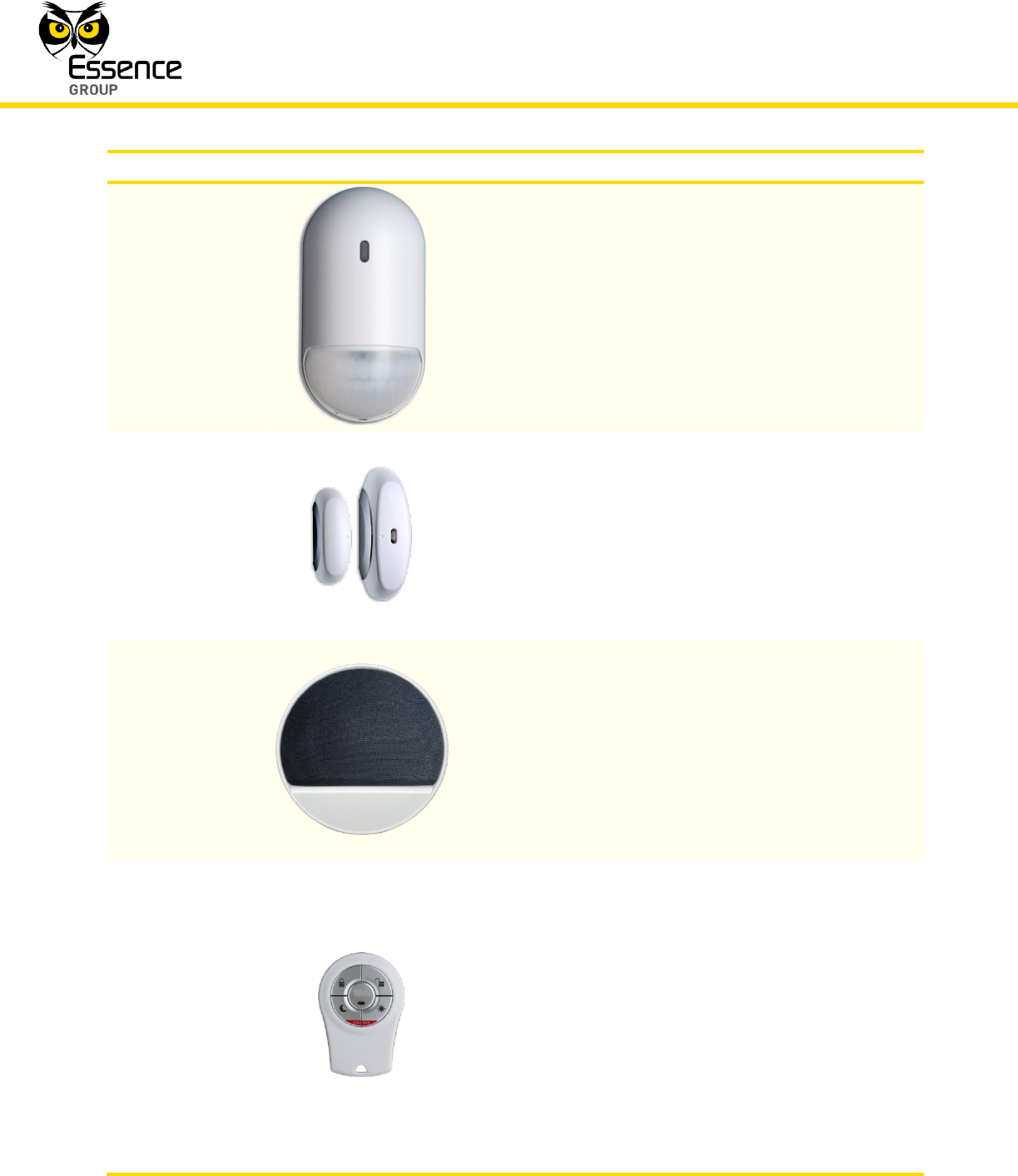
Motion Detector
(PIR) – Essence
ES800PIR
A Passive Infra-Red (PIR) Motion Detector peripheral
device.
It features:
Sealed optics, immune to light and insects for
reduction of false alarms.
Multi-zone spherical lens for wide detection
coverage (120o horizontal, 105o vertical).
Walk-through test mode.
Door/Window
Magnetic Sensor
(MGL) – Essence
ES800MGL
Compact design magnet detector peripheral device,
with long range and easy to install. Referred to as
Door/Window Sensor.
It features:
Dual LED for open/close status indication.
Composed of a lightweight detector and a
magnet.
Indoor Siren (SRN)
– Essence
ES800SRN
A wireless Siren peripheral device, powerful and
battery-operated.
It features:
Emits loud and powerful siren of up to 95dB
with adjustable volume control.
Emits sound for 90 seconds upon intrusion.
Dual purpose as a siren and doorbell.
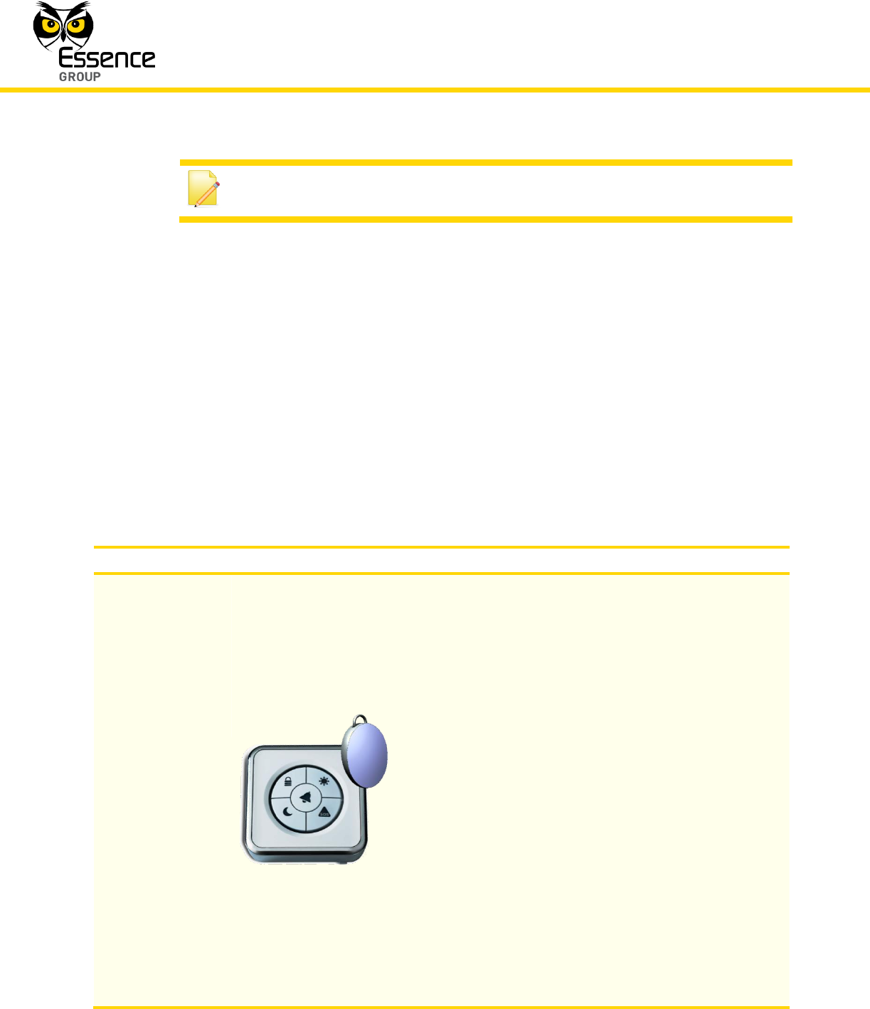
Remote Control
Unit (RCU) –
Essence ES800KF
A Bi-directional, ultra-compact, Remote Control Unit.
Also referred to as Key Fob (KF). A peripheral device
serving as the We.R™ system Key Fob as well as
personal SOS alarm (panic) button.
It features:
5-button interface for setting Full, Day, Night
arm/disarm.
Status key/LED indication of system status.
Remote deactivation in case of loss or theft.
Protection against inadvertent press.
Introduction
We.R™ System User Guide
17
Product
Description
LAN Cable
Local Area Network (LAN) cable (Category 5).
A twisted pair cable for carrying the wired data
communication signals. This type of cable is mostly
used in structured cabling for computer networks such
as Ethernet. The cable is used for connecting the CCU
to an Internet port via Switch, Hub, etc.).
Power Adapter
Universal Switching Power Supply converting the
mains voltage into DC power required for the CCU.
The adapter include electrical cord with mini-USB™-
like connector providing the CCU with the power
required for proper operation.
Square Battery
Pack – Essence
MCBT05001
The 3.7VDC, 1400mAh Lithium Polymer rechargeable
battery is the backup power source for the CCU in
case of mains power shortage.
Coin Battery
Provides power to the Remote Control Unit (KF).
Table 1: We.R™ Box Content
The above items, along with the Shortform User Guide comprise the complete content of the
box.
Figure 1: Components Setup in the Box
Remote Control Unit (KF)
Motion
Detector
(PIR)
Siren (SRN)
Central
Control
Unit (CCU)
Camera (IPD)
Door/Window Sensor (MGL)
Introduction
18
We.R™ System User Guide
Note: The LAN cable, Power Adapter and the batteries are packed and
stored under the box inner (black) separator.
Additional devices may be purchased from local distributors as required. These are described
in paragraph 1.4 and Table 2 below.
1.4. Other Available Devices
The system may be expanded with accordance to the premises’ structure and protection
methods, by purchasing additional components (up to the system’s limits detailed in
paragraph 3.15 below).
Such additional components may include components from the basic kit (described in the
above Table 1) or other available components, built to serve special purposes, which are
described in Table 2 below:
Product
Description
Wireless Access
Control Tag
Reader (TR5) –
Essence
ES800TR5 and
Tag (TAG) –
ES800TAG
The Wireless Access Control Tag Reader is an
access control peripheral device. The tags are the
access keys.
It features:
An intuitive user-friendly human interface.
Provides command options to ARM,
DISARM, partial ARM, SOS alarm and
pending indoor or outdoor installation –
doorbell or status functions.
Remote deactivation of tags in case of
loss/theft (via Smartphone or web access).
Wall Mount – Double sided tape or Screws.
Uses three standard AA-size Alkaline
batteries.
Long operation period (up to 36 months).
Tamper Alarm – when detached from wall.
Introduction
We.R™ System User Guide
19
Product
Description
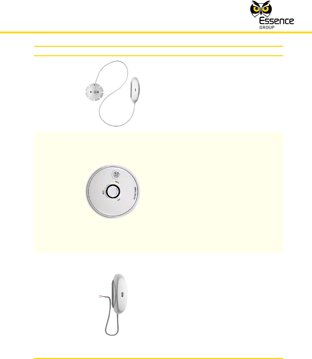
Flood Detector
(FL) – Essence
ES800FL
The Flood Detector is a water outpouring early
warning peripheral device.
It features:
Alarm upon water leakage.
The alarm is triggered upon water running
through the detection element.
Fastened to the wall/frame by double-sided
tape or optional screws.
Smoke Detector
(SK2) – Essence
ES800SK2
The Smoke Detector is a stand-alone fire early
warning peripheral device.
It features:
Tri-color LED for visual indication.
Emits loud alarm sound of 85dB from 3 m.
The Smoke Detector is fully operational even
if the CCU is not.
Tamper Alarm – when detached from its
base.
Long operation life.
Uses three (3) standard AA-size Alkaline
batteries.
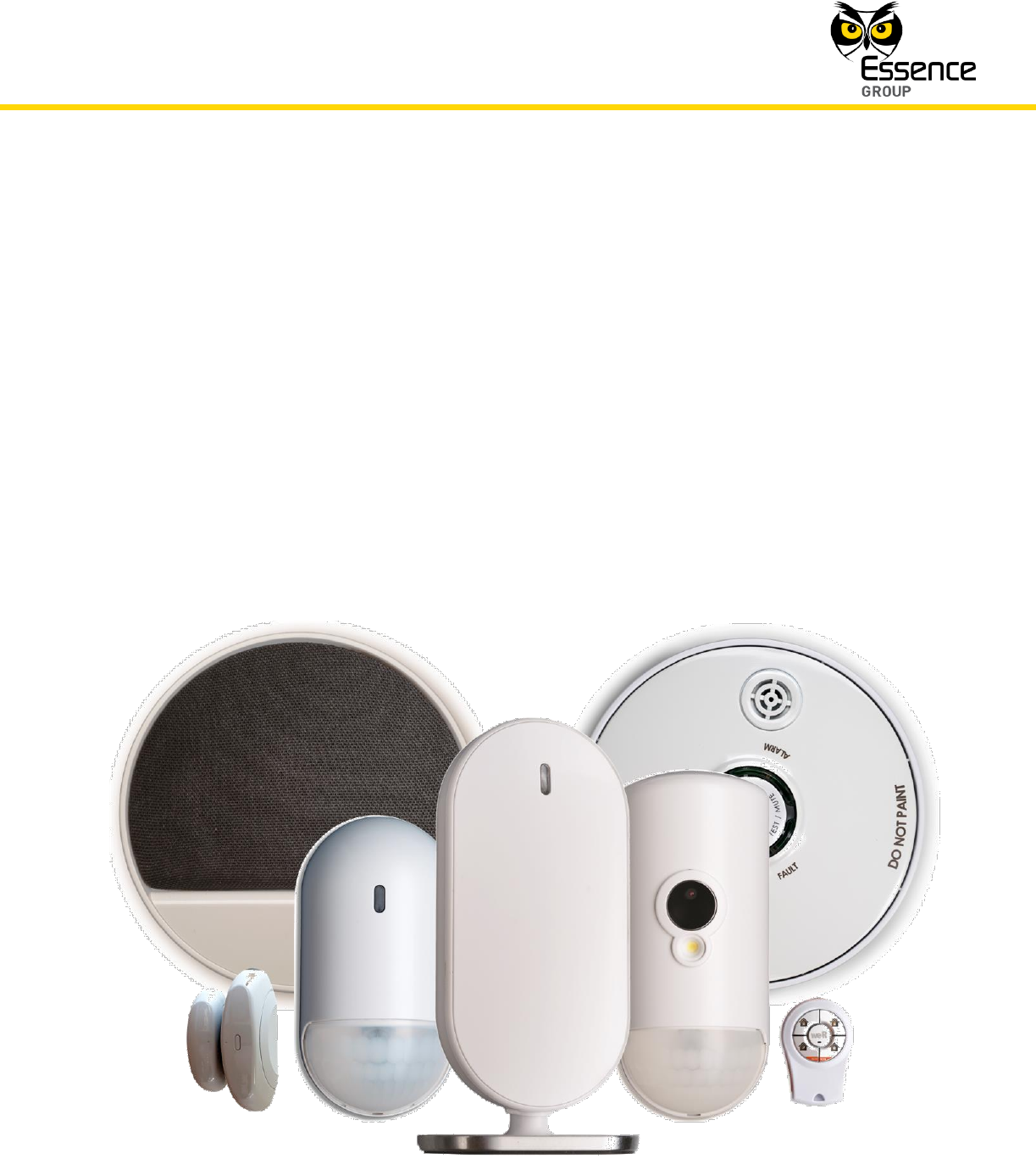
Universal
Transmitter (UT) –
Essence
ES800UT
The Universal Device is a peripheral device enabling
legacy, hard-wired devices interface onto the We.R™
system.
It features:
Dual LED for visual status indication.
Single element – a lightweight RF transmitter
with 30 cm double-isolated two-conductor
cable.
Long operation life.
Uses a single standard AA-size Alkaline
battery.

Introduction
20
We.R™ System User Guide
Product
Description
Z-Wave®
Controller (ZWD)
– Essence
ES800ZWD
The Z-Wave® Controller is a peripheral controller
device enabling integration of Z-Wave® approved
Smart Home devices (i.e. Door Lock, Light
Switch/Dimmer, etc.) onto the We.R™ system.
It features:
Single element.
Long operation life.
Table 2: Other Available Devices
System Theory
We.R™ System User Guide
21
2. System Theory
The We.R™ system transforms mobile smartphones and tablets, as well as personal
computers (PC) into powerful remote control devices that help increase safety and enhance
the quality of life of families. All system components communicate with the Central Control Unit
and the CCU communicates with system servers via the cloud.
The system is based on a modular structure that is flexible in its expansion capabilities –
additional devices may be added to the system as needed.
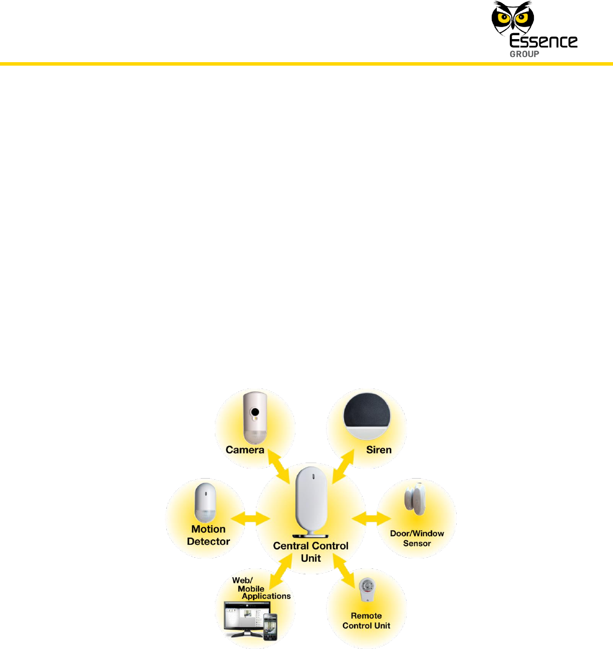
2.1. System Topology
The system consists of the main control component – the Central Control Unit, and
sensors/detectors covering all security aspects and communication components.
It features a comprehensive and expandable sensor/detectors array that provides the flexibility
to create an ideal solution for every Small Office/Home Office (SOHO). Users can add safety
and security accessories, such as additional Cameras, for better protection and monitoring.
Figure 2: We.R™ Home Area Network Components
System Theory
22
We.R™ System User Guide
The We.R™ wireless technology is based on Essence's proprietary Enhanced Controlled Open
Protocol (ECOP), a complete, end-to-end proprietary protocol used throughout the We.R™
system. See details in paragraph 2.3.1 below.
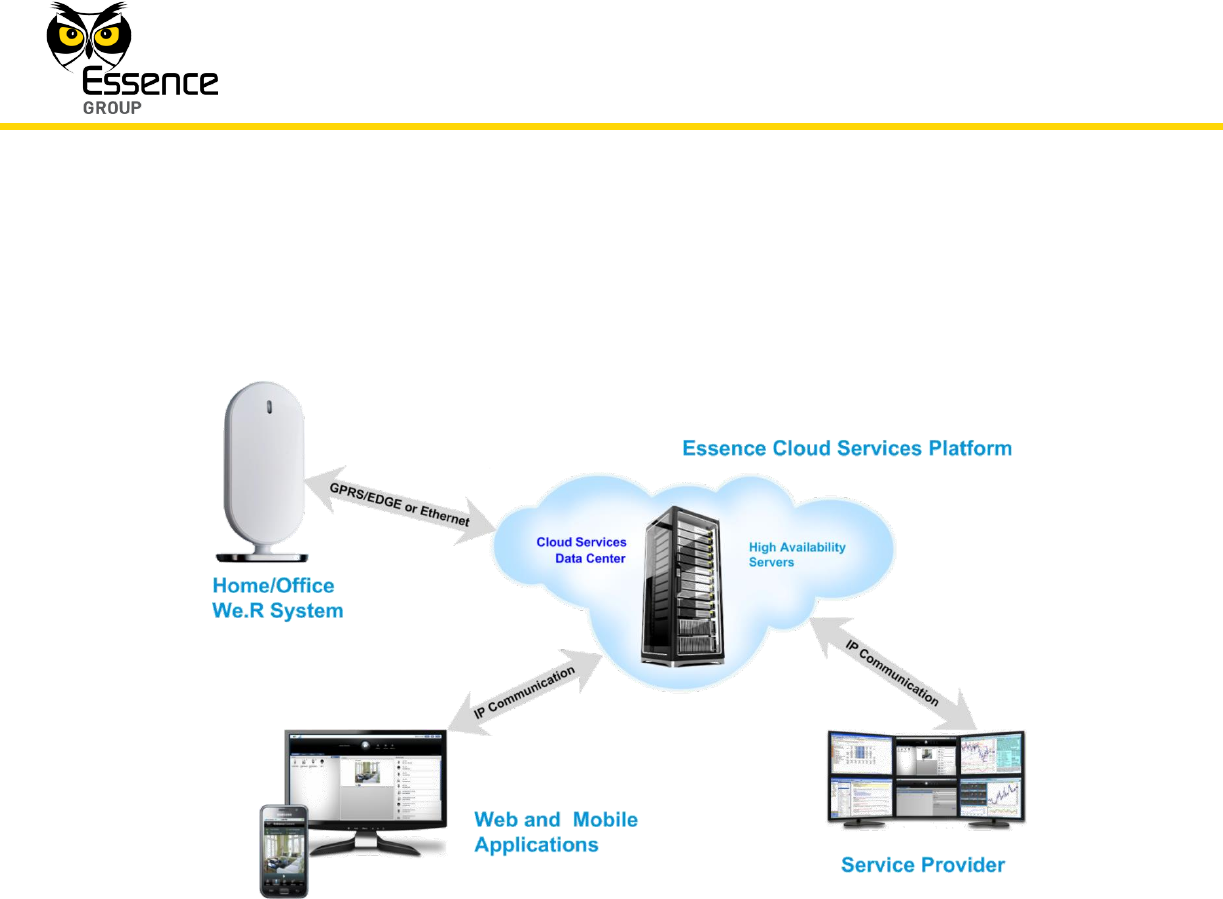
2.2. The Complete System Overview
Figure 3: The We.R™ Cloud Computing Network
The installed system communicates via the cloud platform utilizing the following tools:
User interface software applications:
Web software application running over the Internet and a PC, or
Mobile software application running over GPRS/EDGE cellular network with a
smartphone.
It may communicate with the server via Internet or via GPRS/EDGE cellular channels,
and
The Service Provider utilizes Internet for communication with the server and all of the
Central Control Units.

System Theory
We.R™ System User Guide
23
2.3. Unique Technologies Incorporated
The We.R™ system incorporates some unique technologies and features:
2.3.1. Enhanced Controlled Open Protocol
The We.R™ products intercommunicate with the Central Control Unit (CCU) within the HAN
(Home Area Network) using Essence proprietary Enhanced Controlled Open Protocol (ECOP)
protocol. The We.R™ CCU serves as the gateway between the HAN and the GSM/GPRS or
Internet network.
Between home sensors and home control units (ECOP-R).
For external networks (control unit to the world).
ECOP-X – The XML representation of the ECOP protocol.
Several types of clients (Web Server, iPhone, Windows Mobile, etc.) parse the ECOP protocol.
The ECOP-N protocol is serialized to a standard XML and is transferred to any kind of client (a
distinct ECOP-N protocol parser is not needed for each kind of client).
For details of the RF implementation of the ECOP protocol, please refer to paragraph 2.3.2.
below.
2.3.2. We.R™ RF Technology
2.3.2.1. Radio Interface Information
The We.R™ system works in a star topology where the Central Control Unit acts as the
coordinator, controlling all other sensors and peripherals.
License-free Band Disturbance
Data is sent over the air utilizing the We.R™ proprietary RF protocol (ECOP) in IEEE 802.15.4
standard based on the 2.4 GHz ISM band.
Gateway (GW) uses a band pass filter for out-of-band noise suppression.
In-band noise is compliant with EN-300-440.
Inter-systems disturbance – each system uses a specific, 32bits, system identifier and
filters non-conforming packets.

System Theory
24
We.R™ System User Guide
Power and Sensitivity
We.R™ systems transmit with maximum allowed power according to standard EN 300 –440
(Europe), FCC CFR47 Part 15.
Pending the device, power and sensitivity are divided into two (2) main categories:
Sensitivity Power
-103 dBm (sensors) 14 dBm
-103 dBm (Central Control Unit) 20 dBm
Channels, Bandwidth and Polling
Using ECOP protocol, the We.R™ system utilizes between 1 to 16 channels.
The channel bandwidth is 5MHz.
The We.R™ systems use Beacon-enabled network intervals, about 100ms for quick
response time.
Modulation type: QPSK, 8 chips DSSS
Baud rate: 250KBPS
Low Energy Consumption
ECOP protocol is an externally low-power RF protocol based on 16 years of experience in
battery-operated devices. For example, the system uses a mechanism that significantly
reduces listening time (one of the major drains on battery life).
2.3.3. Remote Software Update
The We.R™ system and its components are being constantly upgraded with regards to the
software embedded into them and with regards to their service software packages.
There is no need for any user involvement in these upgrades as these are overall procedures
automatically activated by the Service Provider.
2.3.4. We.R™ Cloud Services
The servers of the We.R™ cloud services are the central applicative abstract unit designed for
high availability, scalability, robustness, geo-redundancy and security.

System Theory
We.R™ System User Guide
25
The We.R™ Infrastructure is designed to support millions of concurrent users over multiple
client platforms (web application, mobile smartphone and tablets applications, mobile phones
via SMS, and 3rd parties consumer data) on various supported protocols (HTTP, SOAP, JSON,
REST, TCP).
We.R™ Cloud Services concentrate and encapsulate the entire communication and logic,
allowing users to easily install and enjoy a simplified world of seamless communication
between them, their homes and their mobile/web devices.
Operators can exercise full real-time control over all system functions, overview the full picture
regarding customer usage, analyze usage patterns and preferences and customize services
and activation for each account.
The We.R™ Cloud Services are based on a few fundamental building blocks, like:
Asynchronous messaging mechanism.
Control the devices’ communication layer.
Account management.
Account activation/deactivation/suspension, user preferences.
Monitoring System – Logging, Tracing, Monitoring and Audit.
Message handling and events logic in addition to rules engine.
Archive mechanism.
Protocol adapters and services.
Composition of ECOP-X protocol.
Video services.
Live streaming services.
Video history analysis.
System for remote firmware update.
System for OTA mobile software updates cache distribution custom adaptation.
3rd-party application adaptations.

System Theory
26
We.R™ System User Guide
2.3.4.1. We.R™ Web Server
The We.R™ Web Server is the set of services within the We.R™ cloud designed to:
Allow We.R™ security and Home Automation web application for end users.
Allow the end user to receive full control over his home, including live and archived
images on-demand.
Allow the operator/service provider to fully control account services, view real time
usage statistics and analyze usage patterns and preferences.
The applications are high-end Rich Internet Applications (RIA), scalable and designed for a
smooth user experience while implementing push mechanisms for seamless client/server
communication.
2.3.4.2. Information Consumption Services
The We.R™ system enables access to a special web service layer especially designed for
consumer data such as mobile operators, independent central monitoring stations and other
types of 3rd-party organizations that can benefit from large amounts of mobile/web data and
statistics related to system usage.
2.3.4.3. We.R™ Media Services
The We.R™ System provides real-time continuous-like images supporting monitoring
and security usage.
The system can handle on-demand requests for images.
The system can also generate an automatic image request when the home is armed. If
an alarm is triggered, the system stores the images captured by the Camera to be sent
upon demand to the User.
The system can store the media data on its servers for future access.
Media data is archived, cached and optimized for best performance.
2.3.4.4. We.R™ SMS Services
The We.R™ system supports handsets from all major handset manufacturers, which typically
use common industry protocols and APIs (HTTP, SOAP, etc.).

System Theory
We.R™ System User Guide
27
2.3.4.5. We.R™ Database
The We.R™ system stores all data that is passed through the system. The data is archived for
future use and analysis. Stored data includes:
Video events
Alarms
Event history (alarms, user activity, etc.)
Logs of all commands and actions performed by any user
2.3.4.6. We.R™ Analysis Service
The We.R™ analysis service system is designed to provide business intelligence, data mining
and analysis for the operator and other consumer data.