Essence Security ES800UT Universal transmitter User Manual We R System
Essence Security International ltd. Universal transmitter We R System
Contents
- 1. User_Guide_part1
- 2. User_Guide_part2
- 3. User_Guide_part3
- 4. User_Guide_part7
- 5. User_Guide_part8
User_Guide_part3
Installation of the We.R™ System
82
We.R™ System User Guide
3.5. The Remote Control Unit (KF) – ES800KF
The Remote Control Unit (KF) is a bi-directional ultra-compact We.R™ system control device
with advanced functions for security and automation.
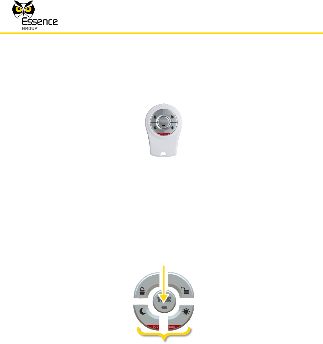
Figure 51: The Remote Control Unit (KF)
3.5.1. The Remote Control Unit (KF) Function
The Remote Control Unit (KF) incorporates the following functions:
End-to-End bi-directional Essence proprietary communication protocol.
LED visual indication of system status (Armed/Alarm triggered).
Serves as personal SOS alarm device (panic button).
5 command keys to perform:
Figure 52: The Remote Control Unit’s Command Keys
ARM
DISARM
Day ARM
Night ARM
SOS (panic)
Status
Installation of the We.R™ System
We.R™ System User Guide
83
Remote deactivation in case of loss or theft.
Powered by a single 3V CR2450 lithium battery.
Long operation period (over 24 months).
Protection mechanisms against inadvertent activation.
Supports automatic over-the-air software upgrade programming and configuration.
3.5.2. Installing and Activating the Remote Control Unit (KF)
Prepare the 3V CR2450 lithium (coin) battery for the KF device before adding it to the system.
Note: You may also want to refer to paragraph 5.1 below to get acquainted
with the process of installing/replacing a battery in the KF.
1. Press any of the KF’s keys for a while to discharge its circuit.
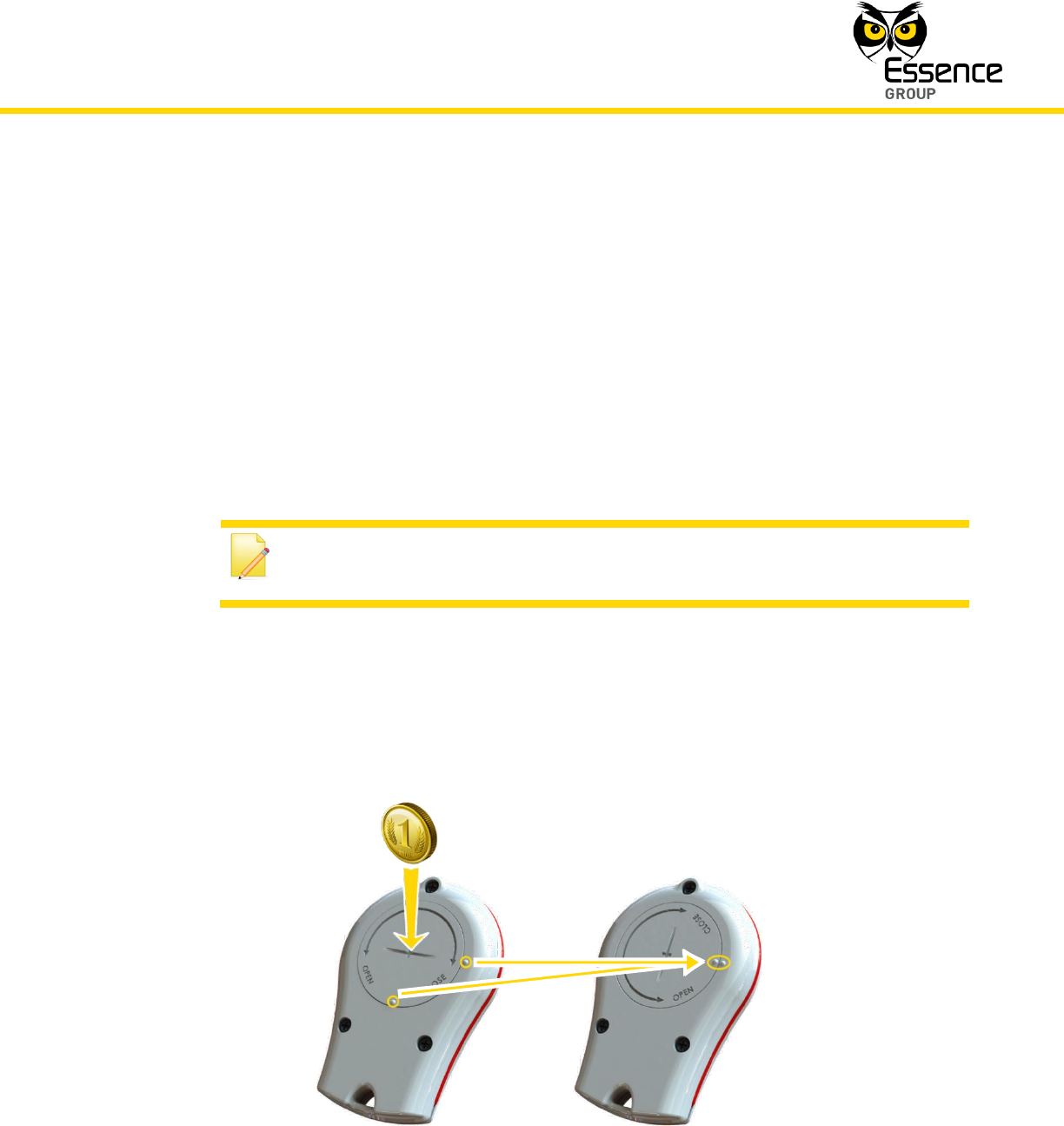
2. Release the cover of the KF battery compartment by inserting a coin into the slot and
turning the cover a quarter of a circle (90o) counter-clockwise until the two small bumps
align (facing each other) as presented in Figure 53 below:
Figure 53: Releasing the Remote Control Unit’s Battery Cover
Installation of the We.R™ System
84
We.R™ System User Guide
3. Remove the cover.
4. Activate the Web Application.
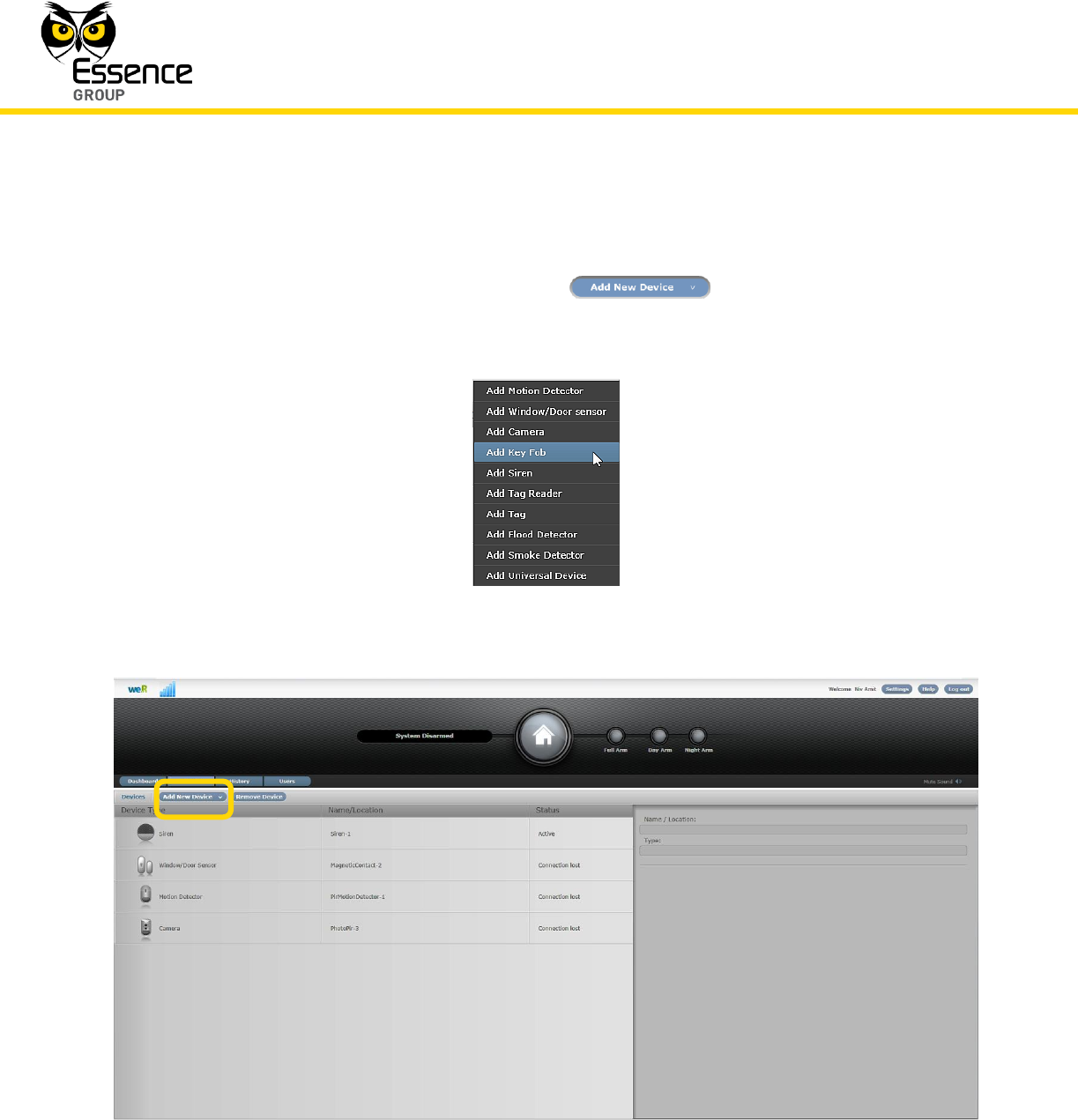
5. Click over the Devices tab and then – over the button.
6. A roll-down menu will open where you need to select Add Key Fob.
Figure 54: Add Device Roll-down Menu
Figure 55: First Steps of Adding a New Device
Installation of the We.R™ System
We.R™ System User Guide
85
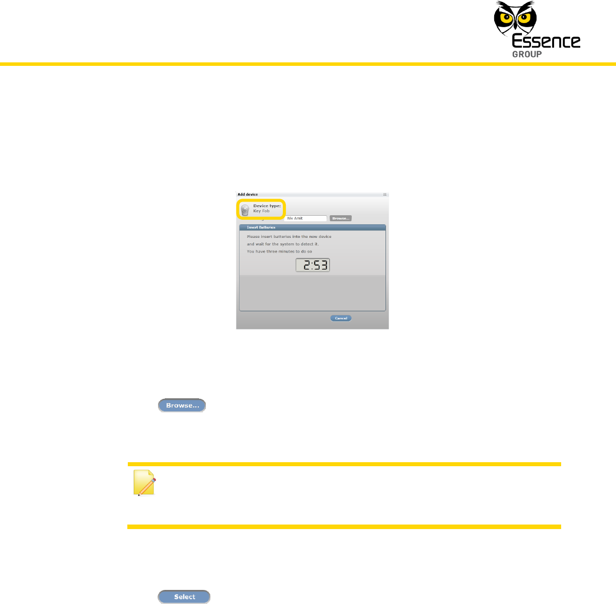
7. Add Device window will pop-up (see Figure 56 below).
8. Verify that Device Type is Key Fob.
Figure 56: Add Device Window – Key Fob
9. Click over the button to open the list of all pre-defined system Users (see
paragraph 3.3.6.4 above).
Note: The Remote Control Unit is a specific User device therefore; its User
need to be defined/added prior to the following described User
assignment.
10. Select the specific User this Remote Control Unit (KF) should be assigned by clicking over
its name.
11. Click over the button to assign the Remote Control Unit (KF) to its specified
User.
12. The assigned User name will be displayed on the Add Device window (above Figure 56).
13. The timer will start its count-down. It provides a time-frame of three (3) minutes within
which the battery should be installed.

Installation of the We.R™ System
86
We.R™ System User Guide
Note: In case the installation of the battery could not be completed within
the three (3) minutes period, it is possible to restart the process by applying
steps 3 (page 84) and onwards again.
14. Insert the battery into the Key Fob’s cavity with its pole facing out/up as demonstrated in
Figure 57 below.
Figure 57: Inserting the Remote Control Unit’s Battery
18. Seal the cover by turning it a quarter of a circle (90o) clockwise.
19. A built-in software will:
i. Trigger a self-test program which will cause the Remote Control Unit’s entire front
panel LEDs to blink twice to indicate that the battery was properly installed.
ii. Triggers an automatic software handshake procedure in which the KF communicates
with the Central Control Unit to flag its presence.
20. Other ways to verify that the Remote Control Unit (KF) was properly added to the system
are:
i. By pressing the Status key to see the right status LED turning ON (see sub-
paragraph 3.5.3 below), or,
Installation of the We.R™ System
We.R™ System User Guide
87
ii. By checking the details of the We.R™ Web Application’s Devices page to see that the
Key Fob icon is on display.
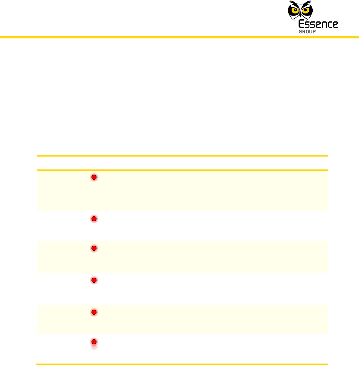
3.5.3. The Remote Control Unit (KF) Status Reporting
Table 4 below summarizes all possible states of the Key Fob LED display, presented following
press over the Status Key.
LED (under key)
Status
Duration
Description
Status
ON
red
Short
A quick press on the Status key will turn ON the
status LED correlating with the current system
status. Blinking LED following an additional press
over another key means the KF’s battery is low.
Disarm
ON
red
Short
System fully dis-armed.
Night Arm
ON
red
Short
System partially armed in accordance with night
scenario defined from within the Web
Application.
Day Arm
ON
red
Short
System partially armed in accordance with day
scenario defined from within the Web
Application.
(full) Arm
ON
red
Short
System is fully armed.
All LEDs
Blinks
red
Five (5) times
An alarm was triggered (burglary in progress).
Table 4: Remote Control Unit (KF) LED Indications
Installation of the We.R™ System
88
We.R™ System User Guide
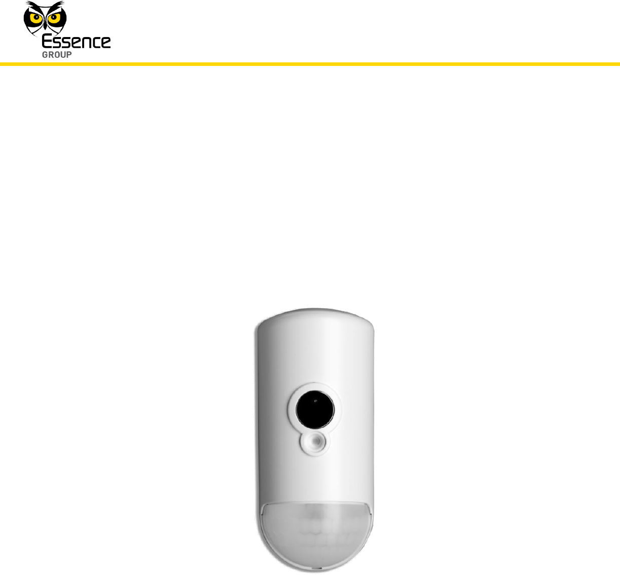
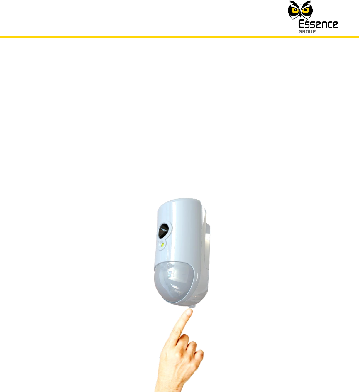
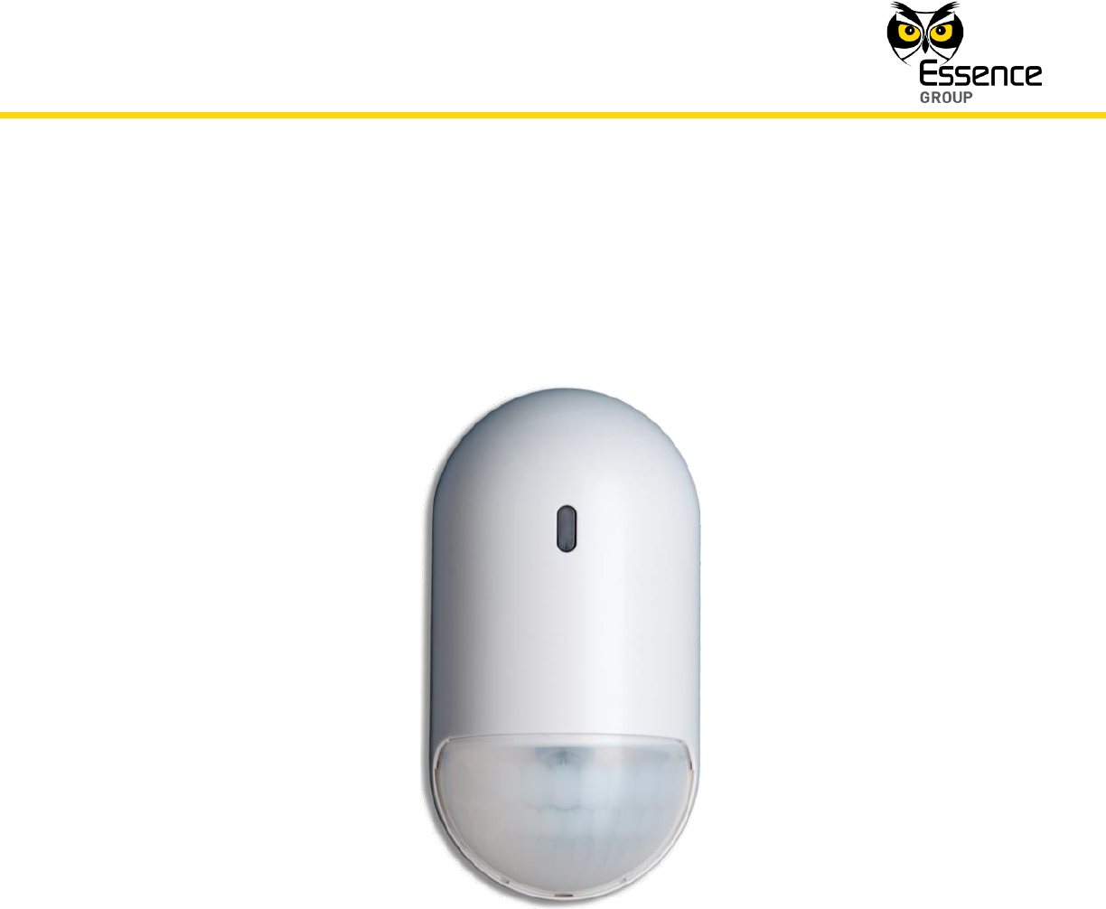
3.6. The Motion Indoor Photo Detector (IPD) – ES800IPD
The Motion Indoor Photo Detector (referred to as Camera or IPD) is a We.R™ indoor sensor
combining Passive Infrared (PIR) motion detector with a video-like, high-resolution, full-color,
JPEG images capturing camera.
Accessories available for the Camera:
Double-sided adhesive tape.
Pet immune lens (upon request).
Figure 58: The Motion Indoor Photo Detector
3.6.1. The Motion Indoor Photo Detector Function
The Motion Indoor Photo Detector (IPD) incorporates the following functions:

Installation of the We.R™ System
We.R™ System User Guide
89
Both security and comfort look-in motion detected image sequences via a smartphone
and the Web Applications.
On-demand or PIR-triggered photo verification capabilities – captures high resolution,
full-color JPEG images at rate of up to 5 frames per second, with automatic selection
of quality/resolution – from 80x60 to 640x480.
Compresses the photos data streams sent in real-time via ECOP RF to the CCU.
These streams are relayed to a designated device (smartphone, computer, etc.).
On-board Flash Memory for Video clip re-transmissions.
Data security is ensured with 128-bit AES encryption.
Up to 500m (1640 feet) RF range (open air) communication.
Employs sealed optics and temperature compensation for the PIR to become immune
to direct light, insects, and pets (optional) for reduction of false alarms.
Utilizes multi-zone spherical lens for exceptional detection coverage (120o horizontal,
105o vertical) and detection range of about 12m (40ft).
Supports automatic over-the-air software upgrade programming and configuration.
Tamper Alarm – when the unit is tilted.
Provides long operation period (pending video look-in usage) while powered by three
(3) standard AA-size Alkaline batteries.
Super bright white LED (flash) for intruder pre-emption in total darkness.
Shooting Angle: 67°.
Shooting Range: Up to 10m (33ft).
3.6.1.1. The Camera Modes of Operation
The Camera can be used in two different modes of operation:
Security Mode – Captures images of intruders caught "red-handed".
Comfort Mode – Remotely activated allowing users to see (via Web Application or the
mobile devices) what happens within the premises, whenever desired.
Installation of the We.R™ System
90
We.R™ System User Guide
3.6.2. Installing the Camera
Note: Rattling sounds might be heard during the installation process of the
Camera. This is the internal tampering prevention mechanism and no
damage was made to the Camera.
The Camera can be mounted on a wall or the corner of a room using the mounting base.
The mounting base is the Camera back cover which should be disassembled from the
Camera, as demonstrated in Figure 59 below, and attached to the wall either by the double-
sided tape (pre-attached to the base) or using screws as demonstrated in Figure 60 below.
Figure 59: Releasing the Camera Wall Mounting Base
Installation of the We.R™ System
We.R™ System User Guide
91
3.6.2.1. Camera Positioning Recommendations
Note: The Camera MUST always be installed with the lens pointing down.
For optimal surveillance, the following factors must be taken into consideration when selecting
the Camera mounting position:
A flat vertical wall surface, or
In a corner of a room (between two walls).
Attach the Camera to a surface that is clean, dry, flat and smooth.
The Camera must be installed with the spherical lens pointing down.
The Camera should not be facing sunlight or other strong light sources including
installation opposite to a window.
The Camera should be placed in a position where it will capture images from the main
point of entry.
For maximal effective detection range, the center of the Camera should be installed 2.1
meters (6.9ft) to 2.3m (7.5ft) above the floor.
Note: Lower positioning of the Camera will limit its detection range.
For daytime coverage – the Camera must be mounted within 10m (33ft) of the desired
coverage area.
For both day and nighttime coverage – the Camera must be mounted within 6m (20ft)
of the desired coverage area.
The Camera must be mounted within 700m (2300ft) (open air nominal) of the CCU.
The wall mounting base includes eight (8) holes to allow maximum flexibility of
installation.
Installation of the We.R™ System
92
We.R™ System User Guide
Extra holes are punch-outs (covered with thin plastic) that may be removed if
necessary.
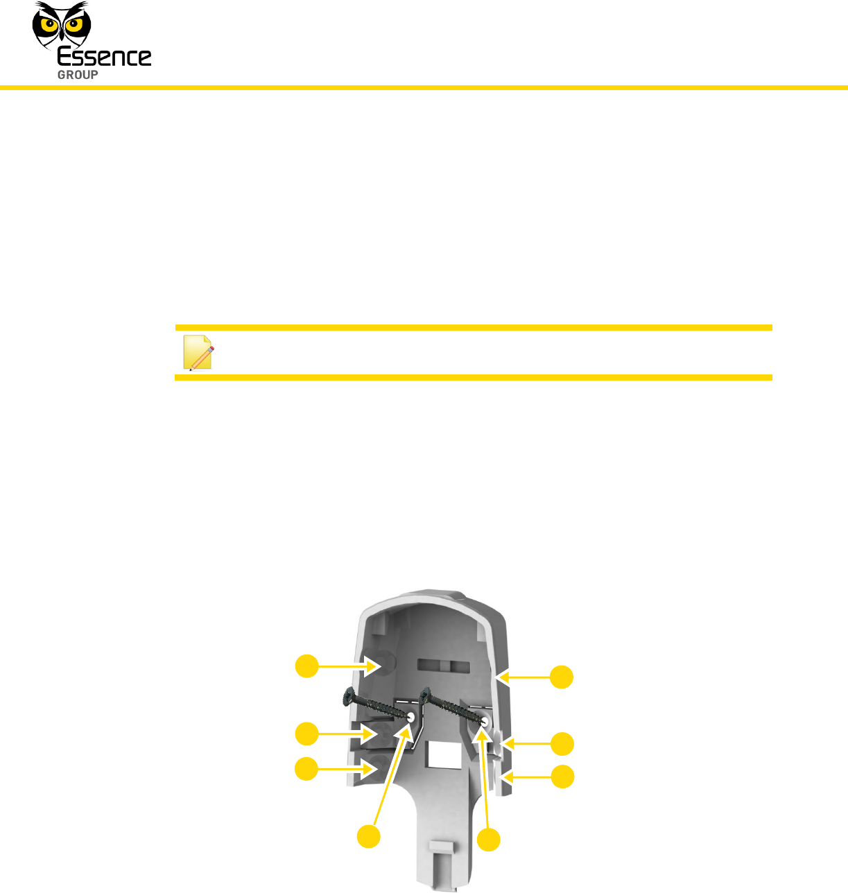
3.6.2.2. Installing with Screws
1. Release the Camera wall mounting back cover by lifting the tab and pushing it forward as
illustrated in Figure 40 above.
2. For Flat Wall Mounting:
i. Use a flat screwdriver to remove the punch-outs 1 and 2 (see Figure 41 above).
ii. Place and hold the base on the desired mounting location and mark the drilling
locations (the above-mentioned punch-outs 1 and 2).
iii. Drill the holes; insert two (2) dowels if needed, place the base over them and screw in
the two (2) screws.
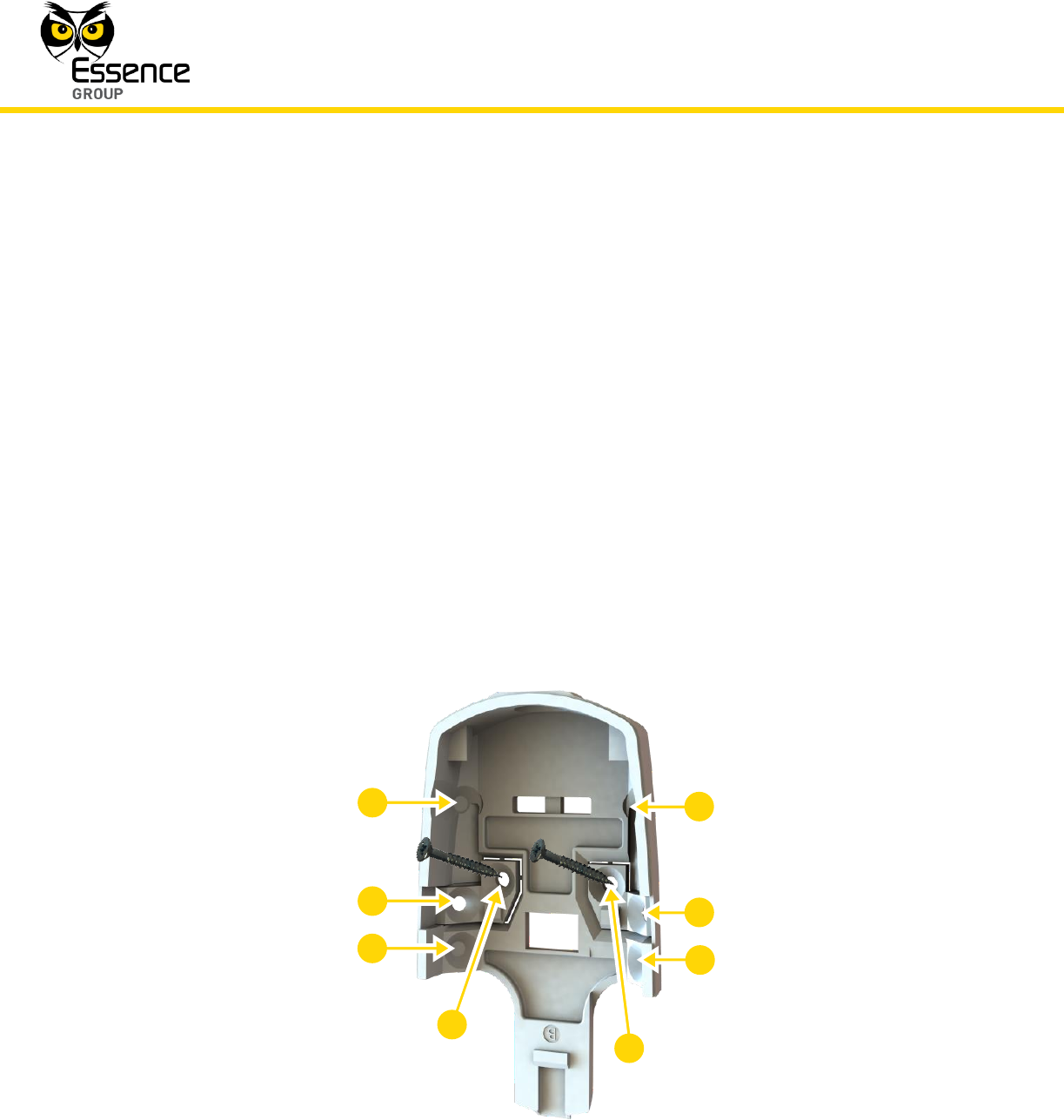
Figure 60: Camera Wall-mounting Base with Screws
3
4
5
8
7
6
2
1
Installation of the We.R™ System
We.R™ System User Guide
93
3. For Corner Mounting:
i. Repeat the above while using punch-outs 3 to 8 as required.
3.6.2.3. Installing with Pre-attached Double-side Tape
1. Release the Camera wall mounting base (above Figure 59).
2. Peel the tapes’ protective covers where needed (position pending).
3. Clean the surfaces were the Camera should be installed.
4. Attach the wall mounting base to its designated location while applying slight pressure.
5. Slide the Camera into the wall mounting base.
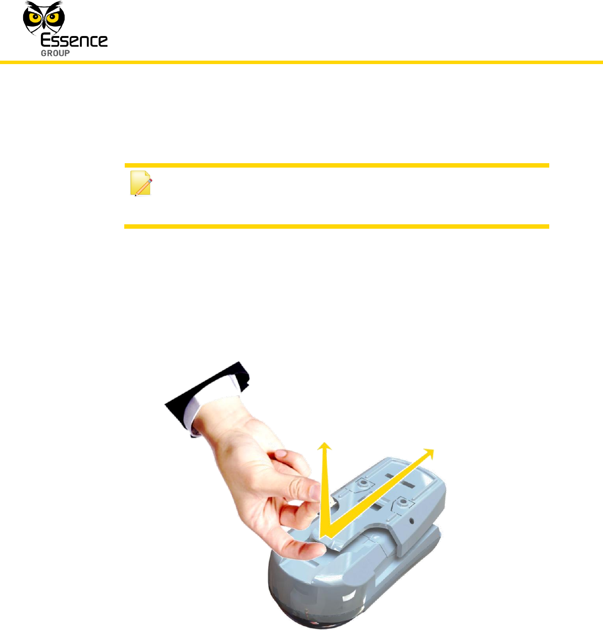
3.6.2.4. Dismounting the Camera
Figure 61: Dismounting the Camera
Installation of the We.R™ System
94
We.R™ System User Guide
3.6.3. Adding the Camera to the We.R™ System
The Camera need to be functionally added to the system following the above described
physical installation procedure. The addition of the Camera is a standard Add Device
procedure performed as follows:
Note: You may also want to refer to paragraph 5.1 below to get acquainted
with the process of installing/ replacing a battery in the Camera.
1. Prepare the three (3) AA-size Alkaline batteries required to power the Camera.
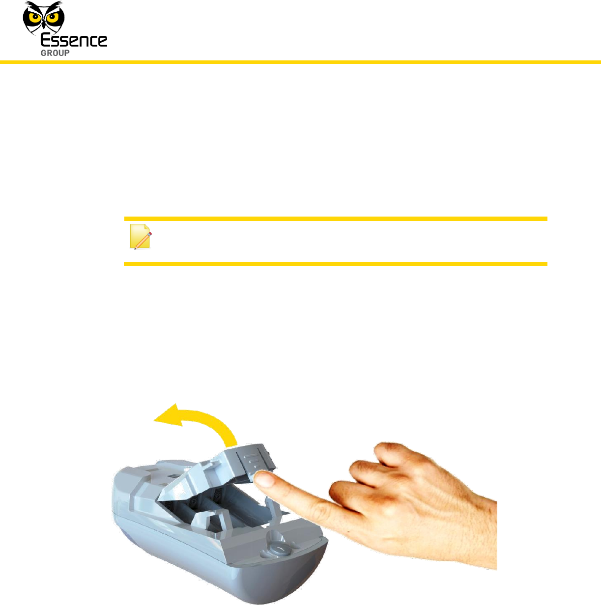
2. Assuming the wall mounting base is already installed – release the batteries (inner) cover.
The release is done by pressing against the inner base (battery cover) tab and twist-lift of
the cover up as demonstrated in Figure 62 below:
Figure 62: Opening the Camera Inner Batteries Cover
Installation of the We.R™ System
We.R™ System User Guide
95
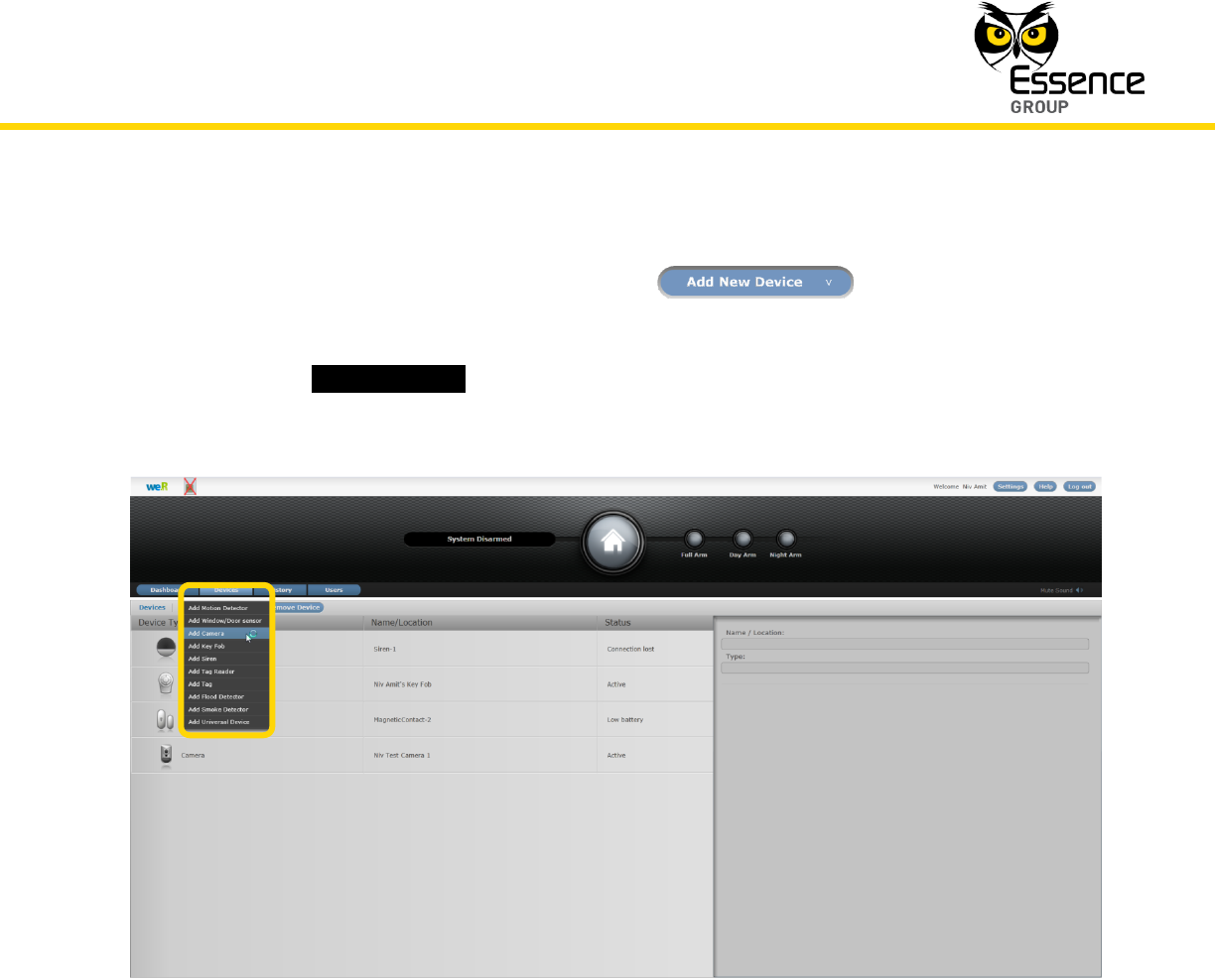
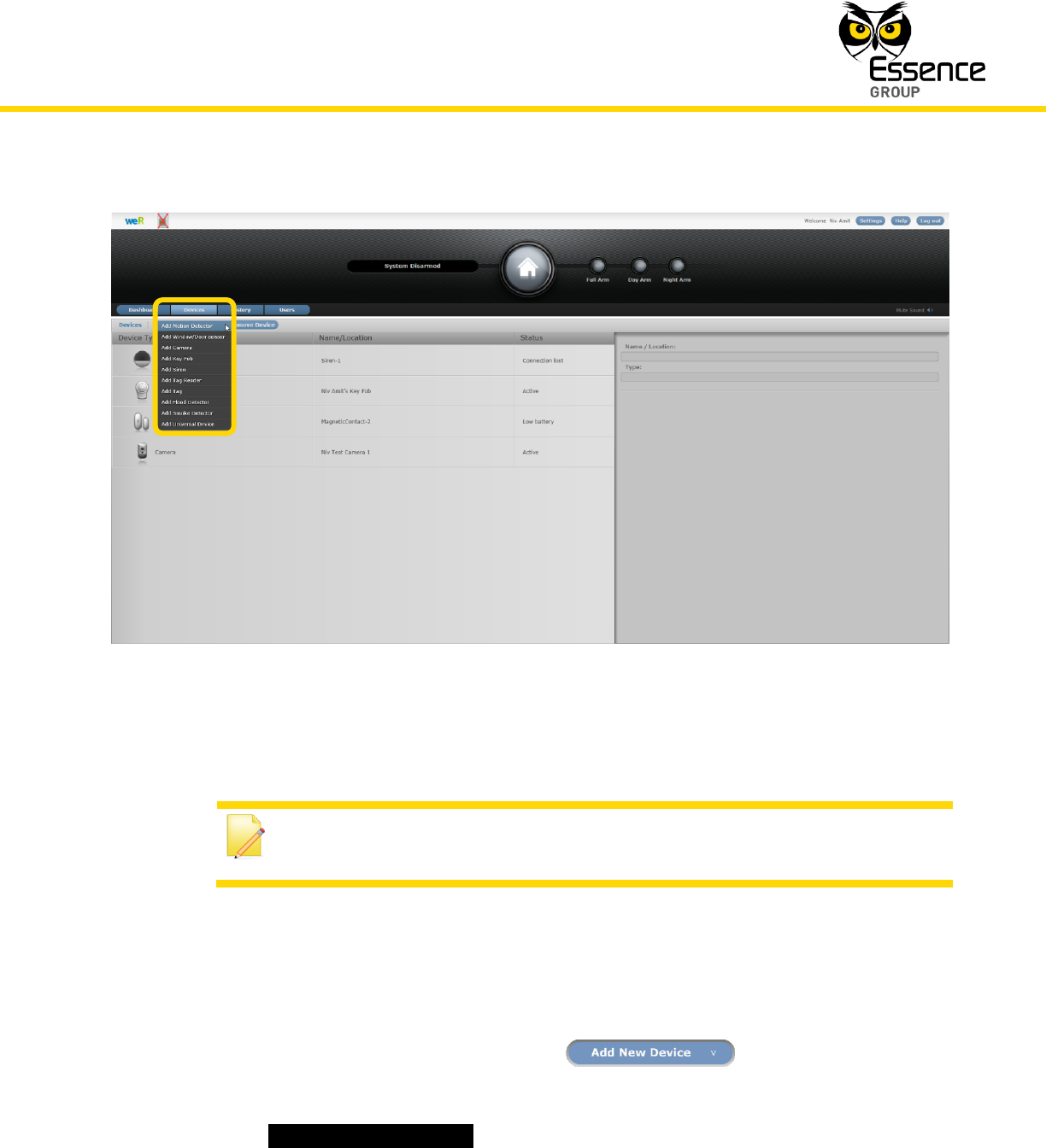
3. Activate the We.R™ Web Application.
4. Select the Devices page (tab) and click over the button.
5. A roll-down selection menu will open.
6. Click over the _Add Camera_ option of the menu as illustrated in Figure 63 below:
Figure 63: Add Camera Device Utilizing Web Application
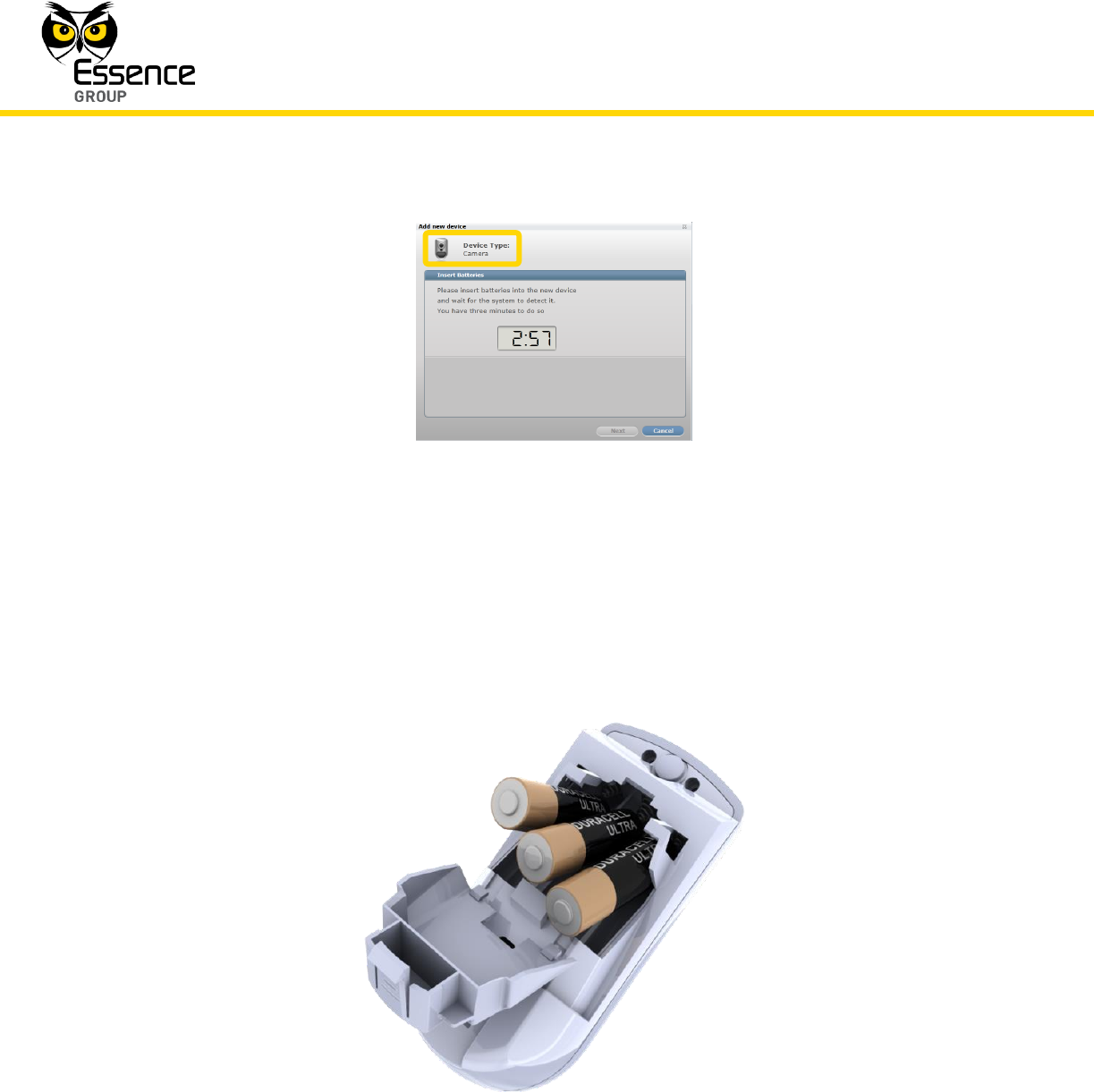
7. An Add New Device (Camera) window will pop-up and its timer will start running.
8. Verify that the Device Type is Camera.
Installation of the We.R™ System
96
We.R™ System User Guide
Figure 64: Add Camera Window
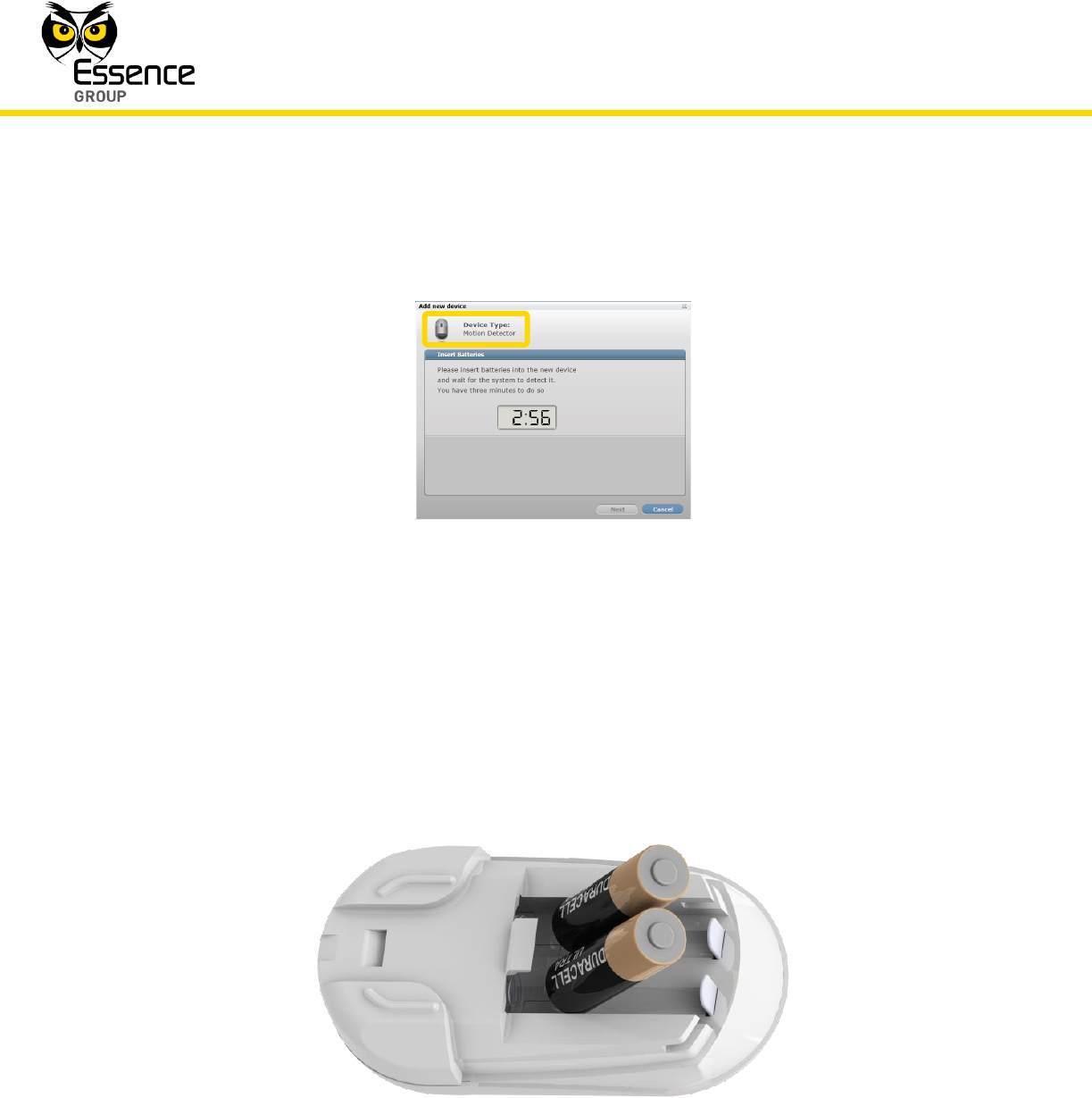
9. The down-counter provides a time-frame of three (3) minutes within which the batteries
should be installed to power-up the camera, as demonstrated in Figure 65 below (the
poles aiming towards the lens):
Figure 65: Inserting Batteries into the Camera
Installation of the We.R™ System
We.R™ System User Guide
97
Note: In case the installation of the batteries could not be accomplished
within the three (3) minutes period, it is possible to restart the process by
applying step 3 (on page 95) and onwards again.
10. Batteries insertion triggers a handshake process in which the Camera communicates with
the CCU to inform it of its presence and the CCU add it to its peripherals’ inventory.
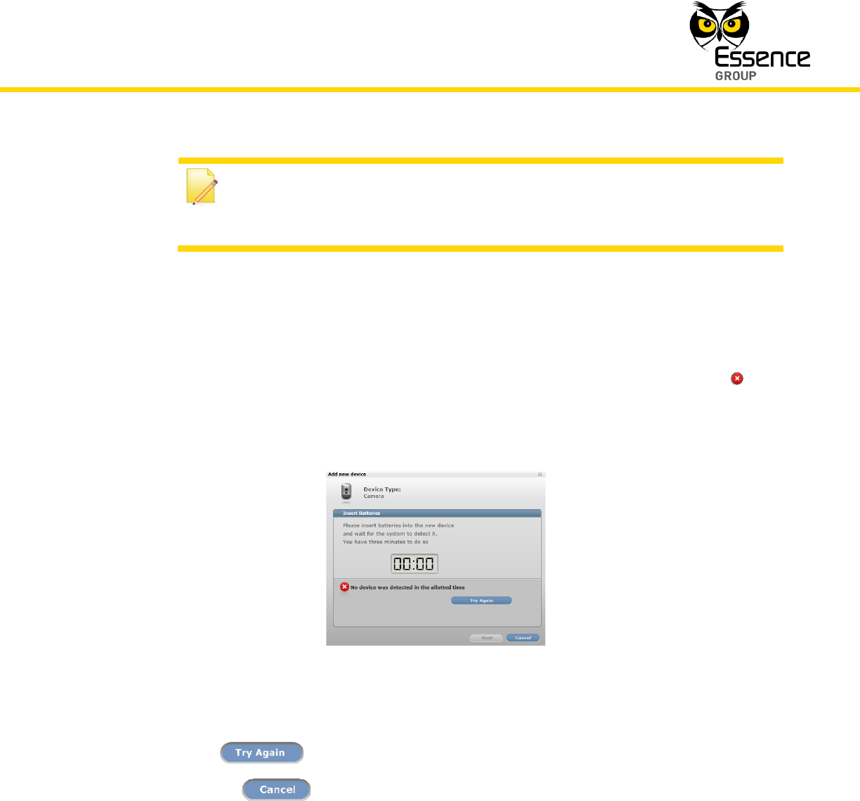
11. If the CCU did not detect the new Camera within this time-frame, the following error ( )
message will appear within the Add New Device window:
Figure 66: Add New Camera Timeout Error Message
Click over the button to re-initiate the Add New Device process by.
Clicking over the button will terminate the Add New Device process.
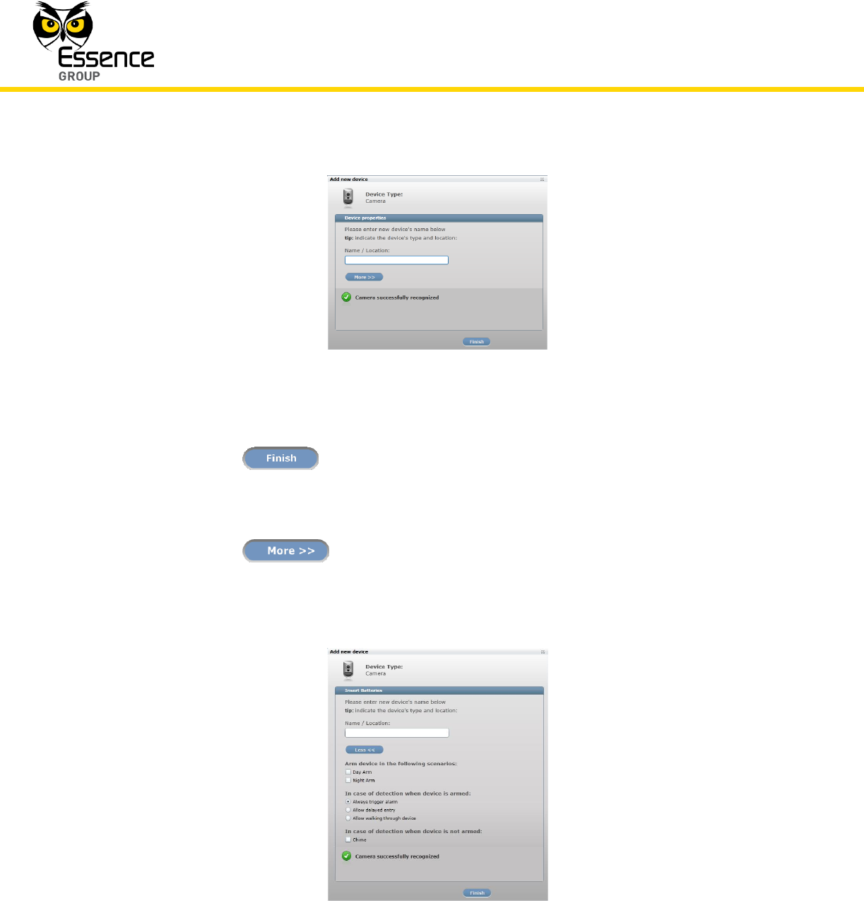
12. If the new Camera was properly detected by the CCU within this time-frame, the counter
will freeze and a Device Properties sub-window will appear within the Add New Device
window, where the Camera’s system name/location needs to be typed-in.
Installation of the We.R™ System
98
We.R™ System User Guide
Figure 67: Add New Camera Device Properties
Clicking over the button will end the Add New Device process while the new
Camera is added onto the system configuration.
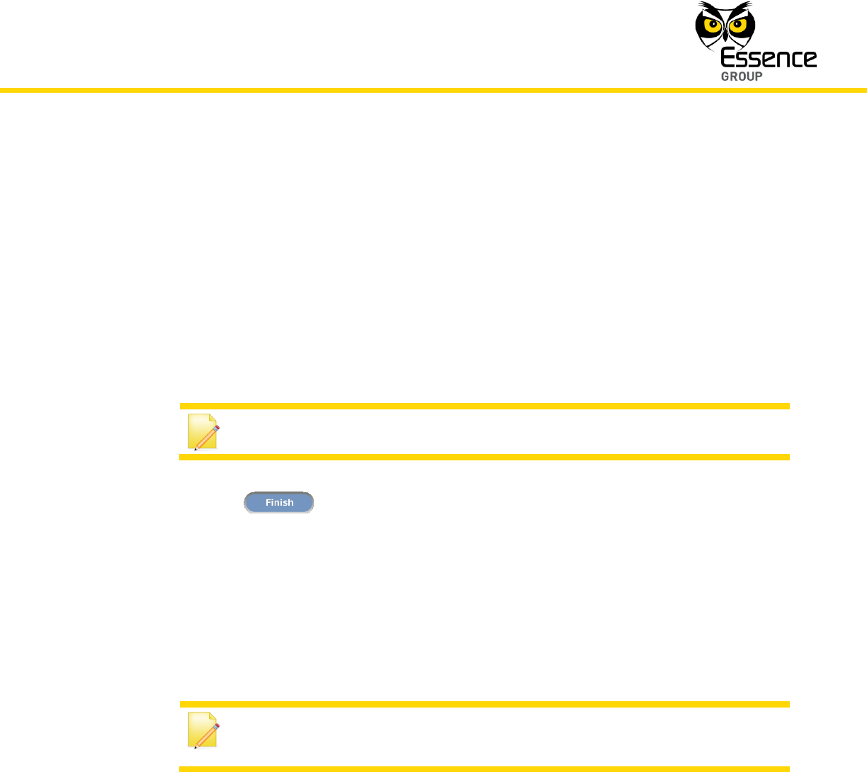
13. Clicking over the button will enlarge this sub-window for further possible
definitions of the Camera’s operation modes.
Figure 68: Add New Camera Detailed Device Properties
Installation of the We.R™ System
We.R™ System User Guide
99
In the case of a Camera, these definitions include:
Camera arming scenarios
Armed Camera detection response
Unarmed Camera detection response
These details may be added or edited later, by a Master User, from within the We.R™ Web
Application’s Devices page.
Note: Paragraph 4 below discuss details of such definitions.
Clicking over the button will end the Add New Device process while the new
Camera is added onto the system configuration with more detailed definitions.
14. Carefully insert the batteries’ cover back to place and firmly close it down.
15. You may verify that the Camera (IPD) was properly added by checking the details of the
We.R™ Web Application’s Devices page.
Note: Advanced Configuration of the Camera can be found in
paragraph 4.5.4 below.
3.6.4. The Camera Operational Modes
The We.R™ system has two operational modes for the IPD devices:
Walk Test Mode
Normal Operation Mode

Installation of the We.R™ System
100
We.R™ System User Guide
3.6.4.1. Walk Test Mode
The Walk Test Mode is a test mode used following a device power-up (replacement of a
battery or once a new Camera was added) for initial testing of the system functionality.
This test runs for about 10-minutes and during this period the device sends an event to the
Central Control Unit following detecting an actual event.
3.6.4.2. Normal Operation Mode
Following the termination of the Walk Test Mode (i.e. after 10 minutes), the system switches
the Camera into Normal Operation Mode. This mode saves Camera battery power.
In this mode, the Camera switches into 2½ minutes hibernation period following a detection
event. This means that the Camera will not transmit events to the Central Control Unit during
this period.
If a detection event occurs during this hibernation, the timer counting the 2½ minutes will
restart and count the 2½ minutes period again.
This process will repeat itself until there is no detection for the entire 2½ minutes.
Following the 2½ minutes hibernation period, the Camera will be switched back to normal
triggering mode of operation.
Note: Advanced Configuration of the Camera can be found in
paragraph 4.5.4 below.
3.7. The Motion Detector (PIR) – ES800PIR
The Motion Detector is a battery operated bi-directional wireless Passive Infrared Detector
(PIR). It utilizes Essence’s unique white 4th generation DragonflyEye™ Multi-Zone spherical lens
with a optional pet immune feature and advanced detection algorithms for false alarm
suppression and excellent detection. The Motion Detector's ease of installation and long
battery life result in reduced operational costs.
Installation of the We.R™ System
We.R™ System User Guide
101
Accessories available for the Motion Detector:
Double-sided adhesive tape.
Pet immune lens (upon request).
Figure 69: The Motion Detector
3.7.1. The Motion Detector Function
The Motion Detector incorporates the following functions:
Data security is ensured with 128-bit AES encryption.
Up to 500m (1640 feet) RF range (open air) communication.

Installation of the We.R™ System
102
We.R™ System User Guide
Employs sealed optics and temperature compensation for the Motion Detector to
become immune to direct light, insects and pets (optional) for reduction of false alarms.
Utilizes multi-zone spherical lens for exceptional detection coverage (90o horizontal,
105o vertical) and detection range of about 12m (39ft).
Supports automatic over-the-air software upgrade programming and configuration.
Walk test mode.
Tamper Alarm – when the unit is tilted.
Provides long operation period while powered by two (2) standard AA-size Alkaline
batteries.
3.7.2. Installing the Motion Detector
Note: Rattling sounds might be heard during the installation process of the
Motion Detector.
This is the internal tampering prevention mechanism and no damage was
made to the Motion Detector.
The Motion Detector can be mounted on a wall, or the corner of a room using the mounting
base.
The mounting base is the Motion Detector back cover (also serving the purpose of batteries’
cover), which should be disassembled from the Motion Detector, as demonstrated in Figure 70
below, and attached to the wall either by the double-sided tape (pre-attached to the base) or
using screws as demonstrated in Figure 71 below.

Installation of the We.R™ System
We.R™ System User Guide
103
Figure 70: Releasing the Motion Detector Wall Mounting Base
3.7.2.1. Motion Detector Positioning Recommendations
Note: The Motion Detector MUST always be installed with the spherical
lens pointing down.
For optimal surveillance, the following factors must be taken into consideration when selecting
the Motion Detector mounting position:
A flat vertical wall surface, or
In a corner of a room (between two walls).
Attach the Motion Detector to a surface that is clean, dry, flat and smooth.
Installation of the We.R™ System
104
We.R™ System User Guide
The Motion Detector must be installed with the spherical lens pointing down.
The Motion Detector should not be facing sunlight or other strong light sources
including installation opposite to a window.
For maximal effective detection range, the center of the Motion Detector should be
installed 2.1 meters (6.9 ft.) to 2.3m (7.5 ft.) above the floor.
Note: Lower positioning of the Motion Detector will limit its detection range.
The Motion Detector must be mounted within 700m (2300ft) (open air nominal) of the
CCU.
The wall mounting base includes eight (8) holes to allow maximum flexibility of
installation.
Six out of these eight are extra holes (punch-outs covered with thin plastic) that may be
removed if necessary.
Figure 71: Motion Detector Wall-mounting Base with Screws
3
4
5
8
7
6
2
1

Installation of the We.R™ System
We.R™ System User Guide
105
3.7.2.2. Installing with Screws
1. Release the Motion Detector wall mounting base by lifting the tab and pushing it forward as
demonstrated in Figure 70 above.
2. For Flat Wall Mounting:
i. Use a flat screwdriver to remove the punch-outs 1 and 2 (see Figure 71 above).
ii. Clean the surface where the Motion Detector is to be installed.
iii. Place and hold the base on the desired mounting location and mark the drilling
locations (the above-mentioned punch-outs 1 and 2).
iv. Drill the holes; insert two (2) dowels if needed, place the base over them and screw in
the two (2) screws.
3. For Corner Mounting:
i. Repeat the above while using punch-outs 3 to 8 as required.
3.7.2.3. Installing with Pre-attached Double-side Tape
1. Release the Motion Detector wall mounting base (above Figure 70).
2. Peel the tapes’ protective covers where needed (position pending).
3. Attach the wall mounting base to its designated location while applying slight pressure.
4. Slide the Motion Detector into the wall mounting base.
3.7.2.4. Dismounting the Motion Detector
For dismounting the Motion Detector from the wall (i.e. in case of battery replacement), press
the wall mounting base's tab at the bottom of the Motion Detector and slide it downwards
simultaneously, as demonstrated in the below Figure 72.

Installation of the We.R™ System
106
We.R™ System User Guide
Figure 72: Dismounting the Motion Detector
3.7.3. Adding the Motion Detector to the We.R™ System
The Motion Detector need to be functionally added to the system following the above
described physical installation procedure.
Addition of Motion Detector device is a standard Add Device procedure performed as follows:
Installation of the We.R™ System
We.R™ System User Guide
107
Figure 73: Add Motion Detector Device Utilizing Web Application
Note: You may also want to refer to paragraph 5.1 below to get acquainted
with the process of installing/ replacing a battery in the Motion Detector.
1. Prepare the two (2) AA-size Alkaline batteries required to power the Motion Detector.
2. Activate the We.R™ Web Application.
3. Select the Devices page (tab) and click over the button.
4. A roll-down selection menu will open.
5. Click over the _Add Motion Detector_ option of the menu as illustrated in Figure 73 above:
Installation of the We.R™ System
108
We.R™ System User Guide
6. An Add New Device (Motion Detector) window will pop-up and its timer will start running.
Figure 74: Add Motion Detector Window
7. Verify that the Device Type is Motion Detector.
8. The down-counter provides a time-frame of three (3) minutes within which the batteries
should be installed to power-up the camera, as demonstrated in Figure 75 below (the
poles aiming towards the top end of the device):
Figure 75: Inserting Batteries into the Motion Detector
Installation of the We.R™ System
We.R™ System User Guide
109
Note: In case the installation of the batteries could not be accomplished
within the three (3) minutes period, it is possible to restart the process by
applying step 1 (on page 107) and onwards again.
9. The insertion of batteries into the Motion Detector triggers a handshake process in which
the Motion Detector communicates with the CCU to inform it of its presence and the CCU
add it to its peripherals’ inventory.
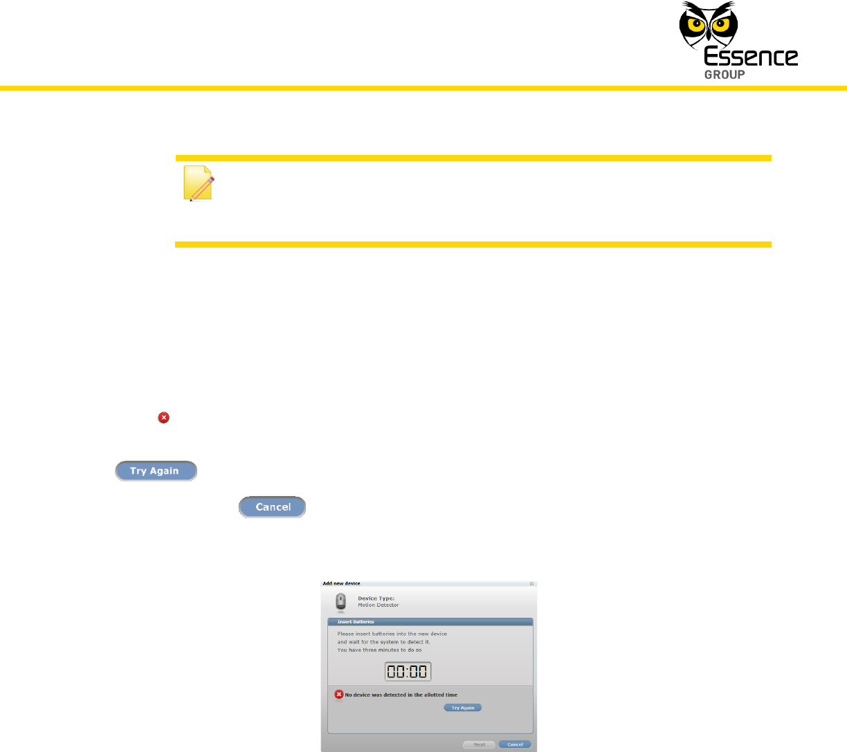
10. If the CCU did not detect the new Motion Detector within this time-frame, the following
error ( ) message will appear within the Add New Device window:
In such a case, it is possible to re-initiate the Add New Device process by clicking over the
button.
Clicking over the button will terminate the Add New Device process.
Figure 76: Add New Motion Detector Timeout Error Message
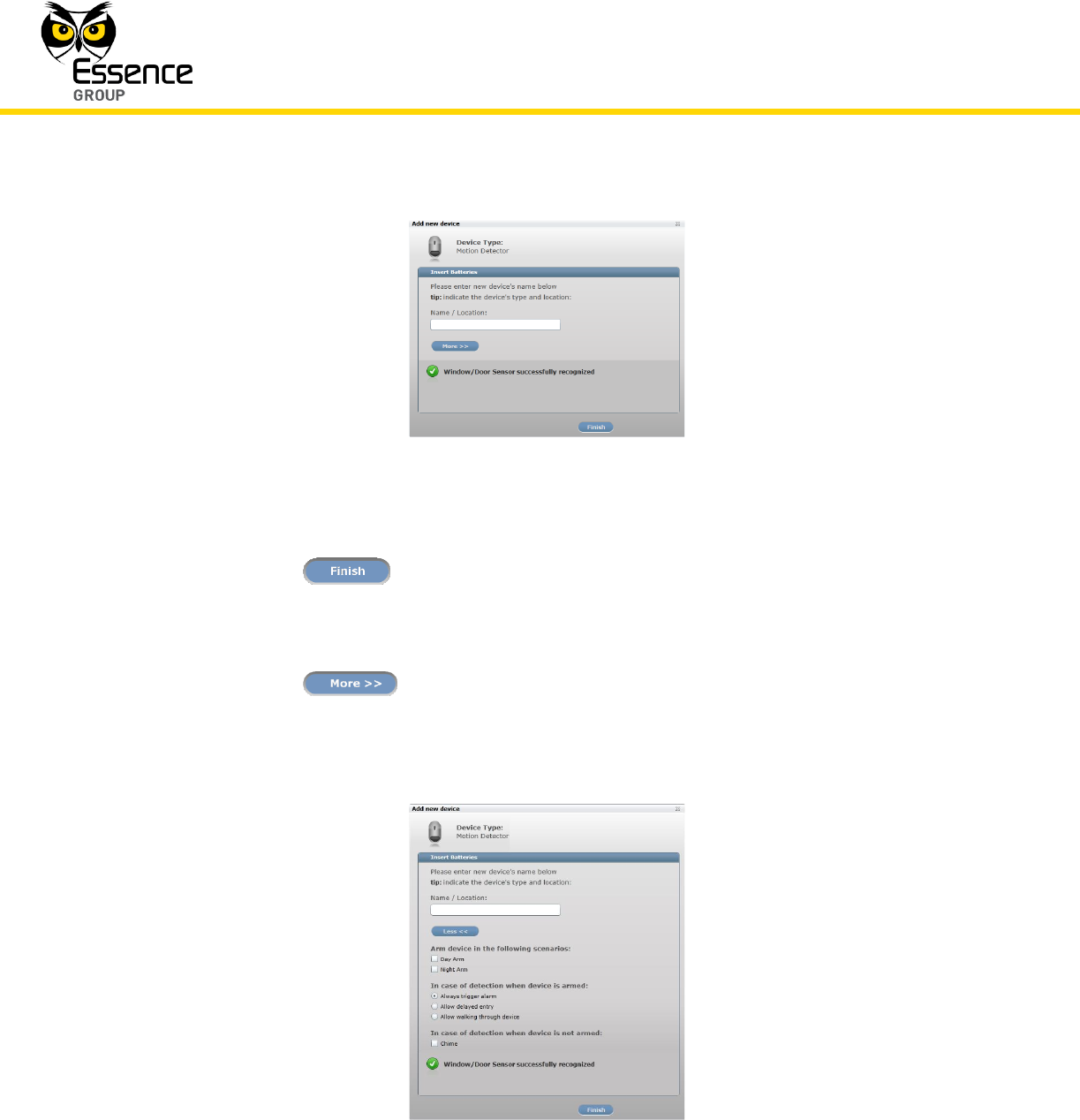
11. If the new Motion Detector was properly detected by the CCU within this time-frame, the
counter will freeze and a Device Properties sub-window will appear within the Add New
Device window, where the Motion Detector’s system name/location needs to be typed-in.
Installation of the We.R™ System
110
We.R™ System User Guide
Figure 77: Add New Motion Detector Device Properties
Clicking over the button will end the Add New Device process while the new
Motion Detector is added onto the system configuration.
12. Clicking over the button will enlarge this sub-window for further possible
definitions of the Motion Detector’s operation modes.
Figure 78: Add New Camera Detailed Device Properties

Installation of the We.R™ System
We.R™ System User Guide
111
In the case of a Motion Detector these definitions include:
Motion Detector arming scenarios
Armed Motion Detector response
Unarmed Motion Detector response
These details may be added or edited later, by a Master User, from within the We.R™ Web
Application’s Devices page.
Clicking over the button will end the Add New Device process while the new
Motion Detector is added onto the system configuration with more detailed definitions.
16. You may verify that the Motion Detector (PIR) was properly added by checking the details
of the We.R™ Web Application’s Devices page.
Note: Advanced Configuration of the Motion Detector can be found in
paragraph 4.5.4 below.
3.7.4. The Motion Detector Operational Modes
The We.R™ system has two operation modes for the Motion Detector devices:
Walk Test Mode
Normal Operation Mode
3.7.4.1. The Walk Test Mode
The Walk Test Mode is a test mode used following a device power-up (replacement of a
battery or after adding the Motion Detector as a new system device) for initial testing of the
system functionality.

Installation of the We.R™ System
112
We.R™ System User Guide
This test runs for about 10-minutes and during this period the device sends an event to the
Central Control Unit following detecting an actual event.
3.7.4.2. The Normal Operation Mode
Following the termination of the Walk Test Mode (i.e. after 10 minutes), the system switches
the Motion Detector into Normal Operation Mode. This mode saves Motion Detector battery
power.
In this mode, the Motion Detector switches into 2½ minutes hibernation period following a
detection event. This means that the Motion Detector will not transmit events to the Central
Control Unit during this period.
If a detection event occurs during this hibernation, the timer counting the 2½ minutes will
restart counting the 2½ minutes.
This process will repeat itself until there is no detection for the entire 2½ minutes.
Following the 2½ minutes hibernation period, the Motion Detector will be switched back to
normal triggering mode of operation.
Note: Advanced Configuration of the Motion Detector can be found in
paragraph 4.5.4 below.
3.8. The Door/Window Magnetic Sensor (MGL) – ES800MGL
The Magnetic Sensor (MGL) is a We.R™ Door/Window Magnetic Sensor/Detector.
This sensor device consists of two (2) parts – a smaller passive magnet unit (the Magnet) and a
larger magnetic detector with a RF transmitter unit (the Transmitter).
Accessories available for the Magnetic Sensor:
Double-sided adhesive tape on both the Transmitter and the Magnet.

Installation of the We.R™ System
We.R™ System User Guide
113
Figure 79: The Magnetic Sensor
3.8.1. The Magnetic Sensor Function
The Magnetic Sensor incorporates the following functions:
Bi-directional wireless sensor.
Detect opening and closing of doors, windows, cabinets, etc.
Dual-LED indication for Open (red) and Close (green) status.
Data security is ensured with 128-bit AES encryption.
Up to 500m (1640 feet) RF range (open air) communication.
Unique electronic serial number.
Supports automatic over-the-air software upgrade programming and configuration.
Tamper Alarm – when the transmitter unit is ripped off its base.
Provides long operation period while powered by a single standard AA-size Alkaline
battery.
3.8.2. Installing the Magnetic Sensor
The Magnetic Sensor can be mounted on a door or a window using the mounting bases.

Installation of the We.R™ System
114
We.R™ System User Guide
Figure 80: Releasing the Transmitter Base
Installation instructions will be divided into two parts:
The installation of the Transmitter
The installation of the Magnet
The mounting base, of both parts, is the Magnetic Sensor back cover (in the Transmitter unit it
also serves the purpose of battery cover).
For the Transmitter unit, the base should be disassembled from the Transmitter body, as
demonstrated in Figure 80 above, and attached to the wall either by the double-sided tape
(pre-attached to the base) or using screws as demonstrated in Figure 83 below.
3.8.2.1. Magnetic Sensor Positioning Recommendations
For optimal surveillance, the following factors must be taken into consideration when selecting
the Magnetic Sensor mounting position:
A flat vertical window or door surface.
Attach the Magnetic Sensor (applicable for both parts) to a surface that is clean, dry,
flat and smooth.
Installation of the We.R™ System
We.R™ System User Guide
115
The Magnetic Sensor must be mounted within 700m (2300ft) (open air nominal) of the
CCU.
Typically, the Transmitter unit will be attached onto the fixed frame of the window/door
while the Magnet unit – to the moving edge.
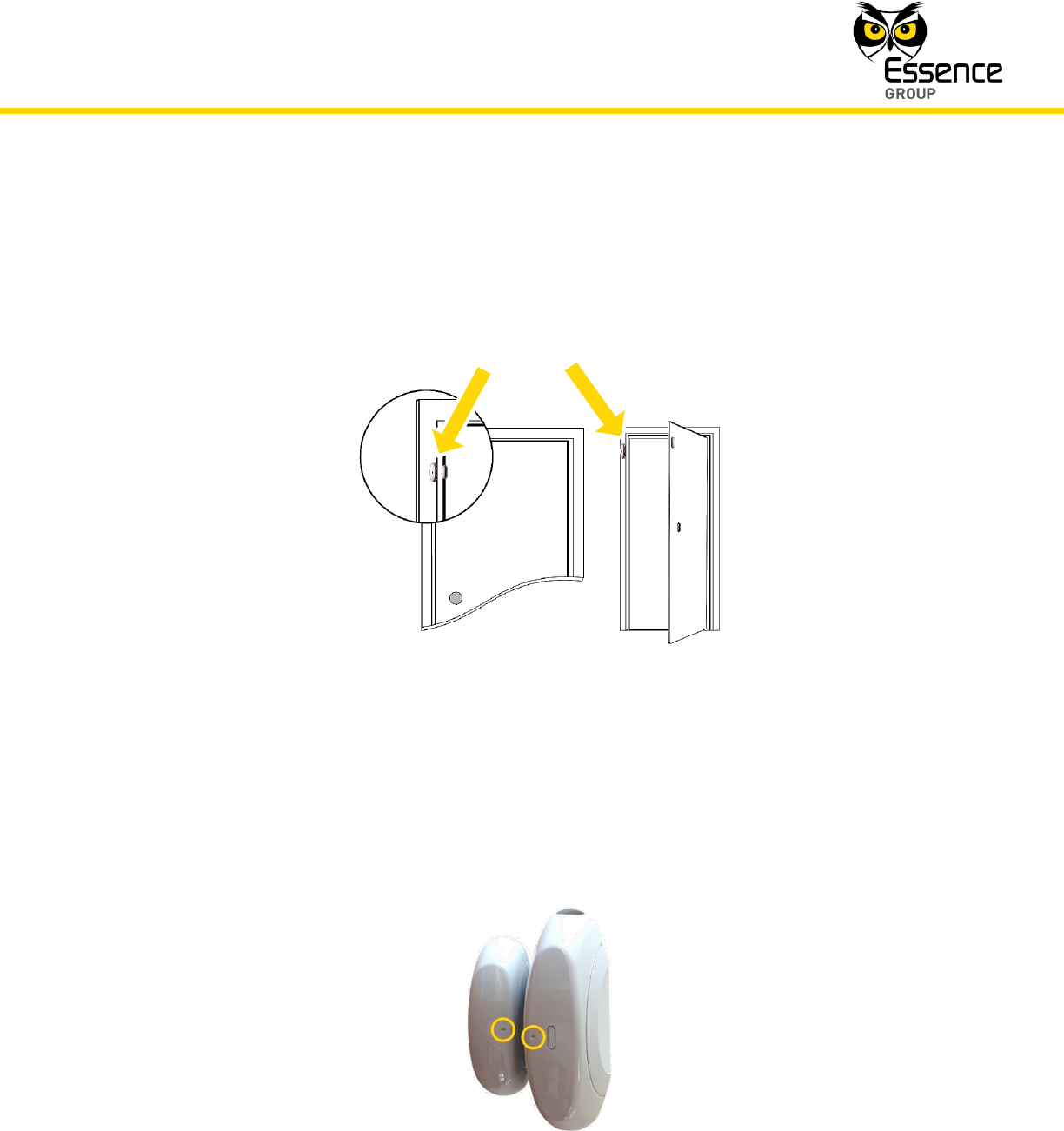
Figure 81: Typical Location for Magnetic Sensor Installation
Special attention should be given, throughout the installation process of the Magnetic
Sensor, to the final arrangement of the two units – they should end up aligned to each
other (dot-to-dot) as demonstrated in Figure 82 below, as well as mounted with 1-2mm
(0.04-0.08 in.) gap between them when door/window is closed.
Figure 82: Dot Alignment of the Magnetic Sensor Units
Installation of the We.R™ System
116
We.R™ System User Guide
3.8.2.2. Installing the Transmitter Unit with Screws
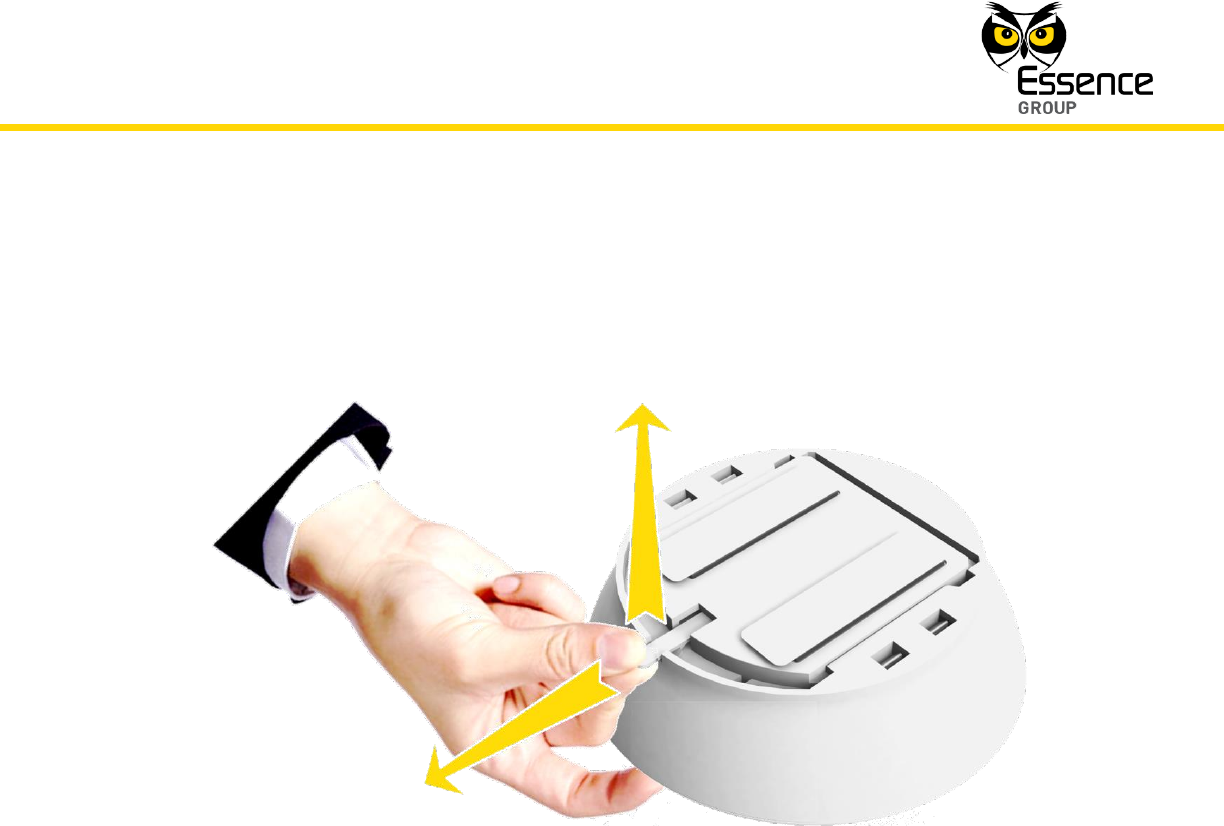
1. Release the Transmitter unit’s base by inserting a coin into one of the edge slots, as
demonstrated in the above Figure 80, and twist it to open the cover.
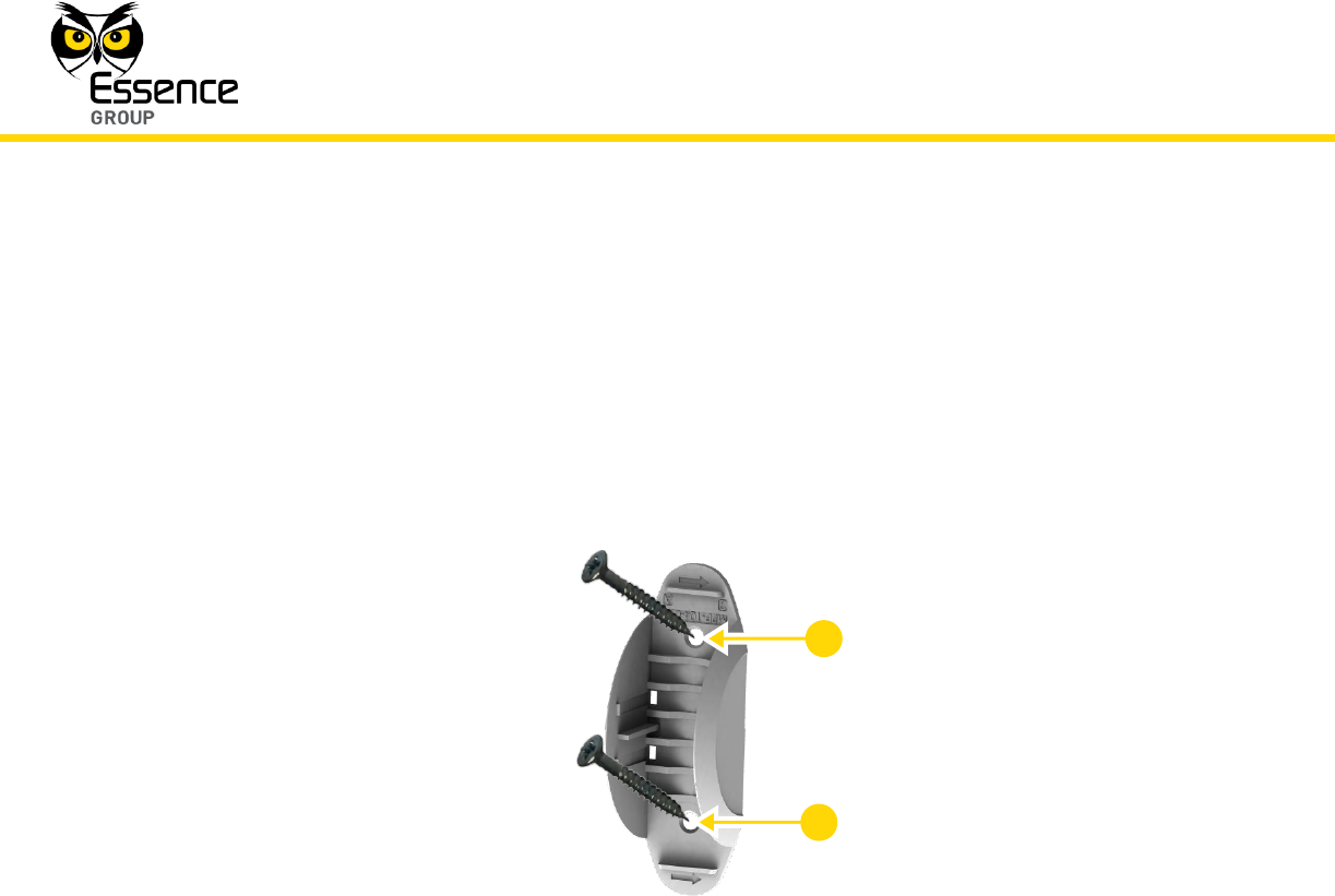
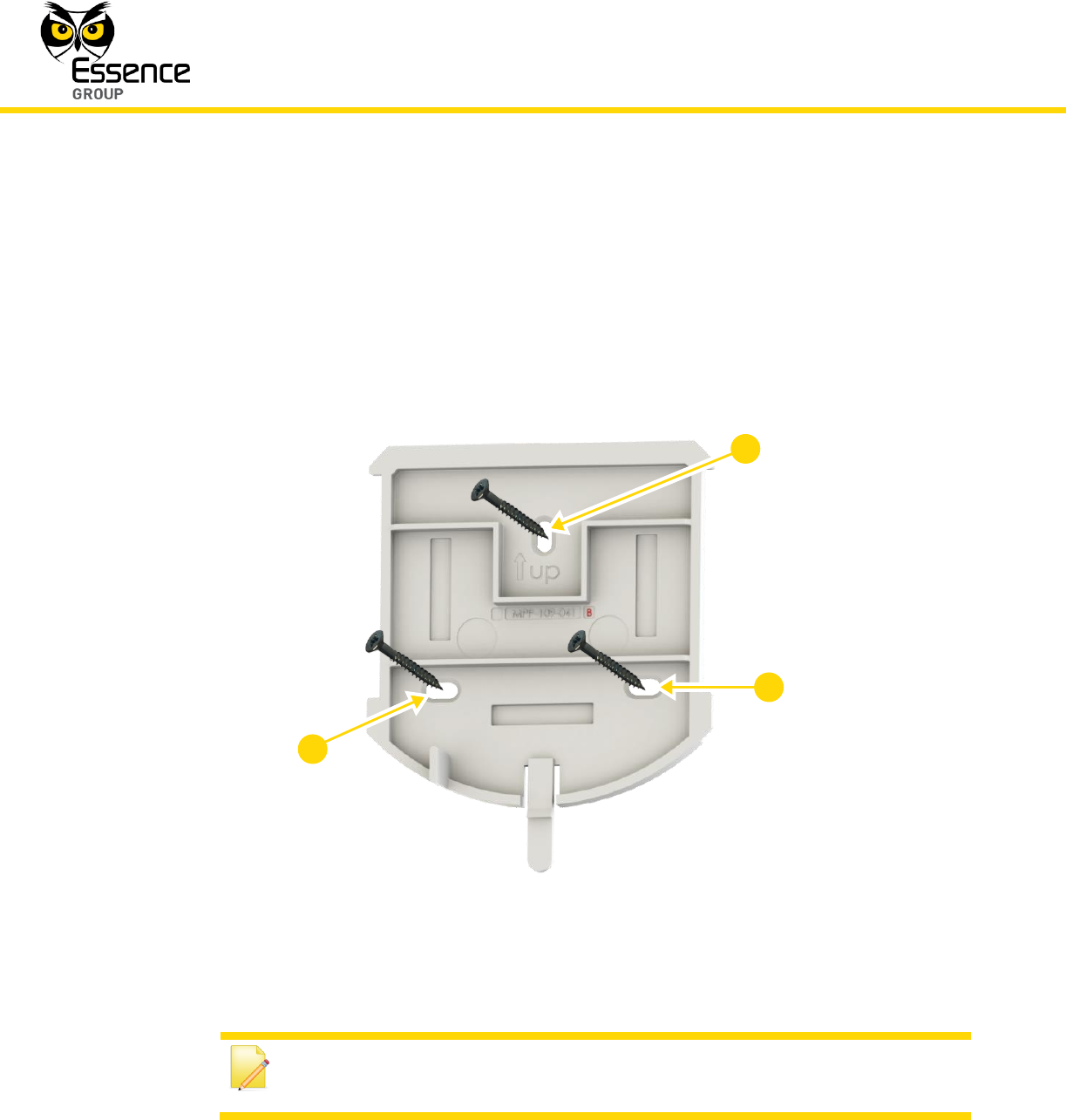
2. Use a flat screwdriver to remove the punch-outs 1 and 2 (see Figure 83 below).
Figure 83: Magnetic Sensor Transmitter Unit Base with Screws
3. Place and hold the base on the desired mounting location on the window/door frame and
mark the drilling locations (the above-mentioned punch-outs 1 and 2).
4. Drill the holes; insert two (2) dowels if needed, place the base over them and screw in the
two (2) screws.
5. Attach the Transmitter Unit back to its base.
3.8.2.3. Installing with Pre-attached Double-side Tape
Due to the common installation (door/window) of the Magnetic Sensor, the pre-attached
double-sided tape will be mostly used for both the Transmitter and the Magnet units.
1. For the Transmitter unit – release the base (see above Figure 80).
2
1
Installation of the We.R™ System
We.R™ System User Guide
117
2. No need to release the base of the Magnet unit.
3. Peel the tapes’ protective covers of both units.
4. Attach the base of each unit to its designated location while applying slight pressure.
5. Attach the Transmitter back into the base.
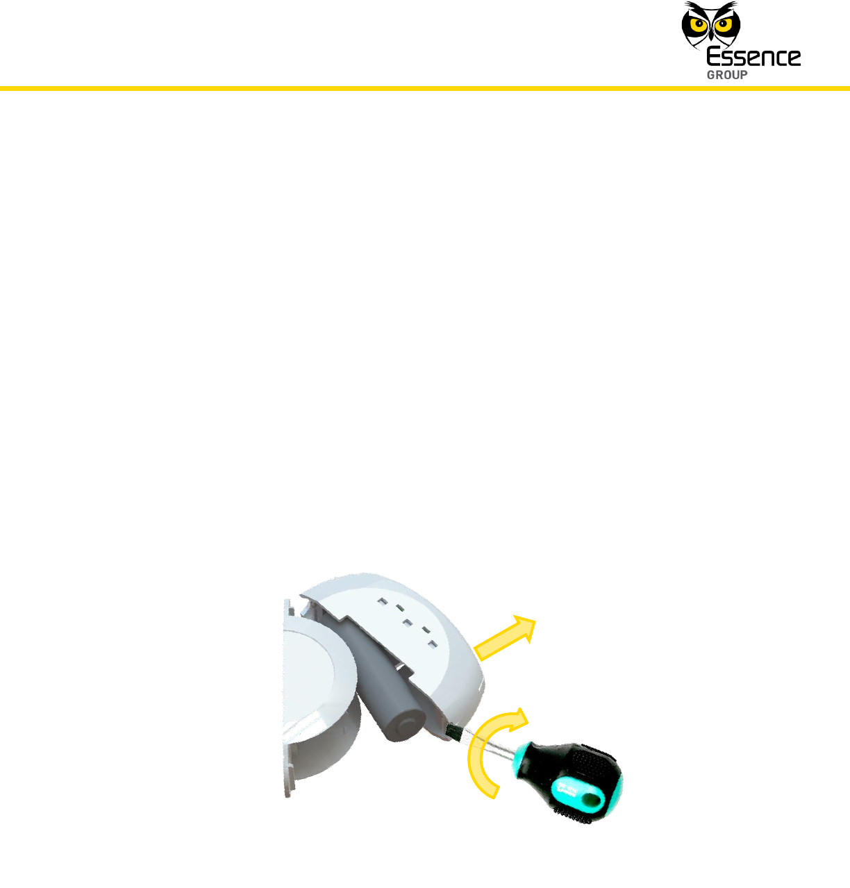
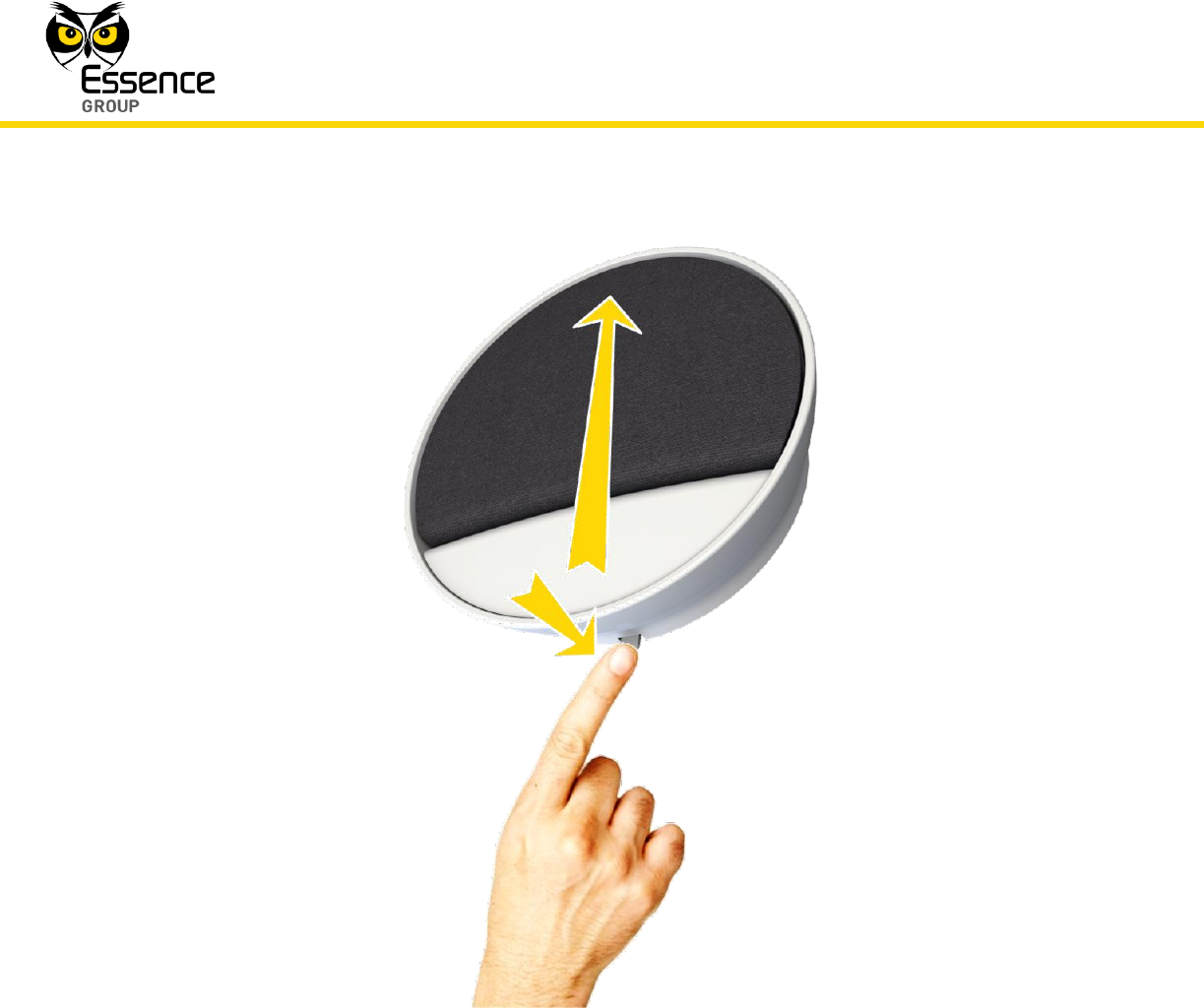
3.8.2.4. Dismounting the Magnetic Sensor
For dismounting the Magnetic Sensor (Transmitter unit only) from the door/window (i.e. in case
of battery replacement):
1. Insert a flat screw driver (or coin) into one of the edge slots as demonstrated in Figure 84
below.
2. Twist it to raise the cover (body) edge.
3. Pull the body strait out of the base’s shoulders.
Figure 84: Dismounting the Magnetic Sensor’s Transmitter

Installation of the We.R™ System
118
We.R™ System User Guide
3.8.3. Adding the Magnetic Sensor to the We.R™ System
The Magnetic Sensor need to be functionally added to the system following the above
described physical installation procedure.
The addition of the Magnetic Sensor is a standard Add Device procedure as follows:
Note: You may also want to refer to paragraph 5.1 below to get acquainted
with the process of installing/ replacing a battery in the Magnetic Sensor.
1. Prepare a single AA-size Alkaline battery required to power the Magnetic Sensor.
2. Activate the We.R™ Web Application.
3. Select the Devices page (tab) and click over the button.
Figure 85: Add Magnetic Sensor Device Utilizing Web Application
Installation of the We.R™ System
We.R™ System User Guide
119
4. A roll-down selection menu will open.
5. Click over the _Add Window/Door Sensor_ option of the menu as illustrated inn Figure 85
above:
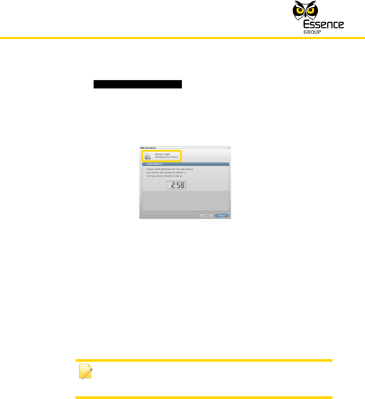
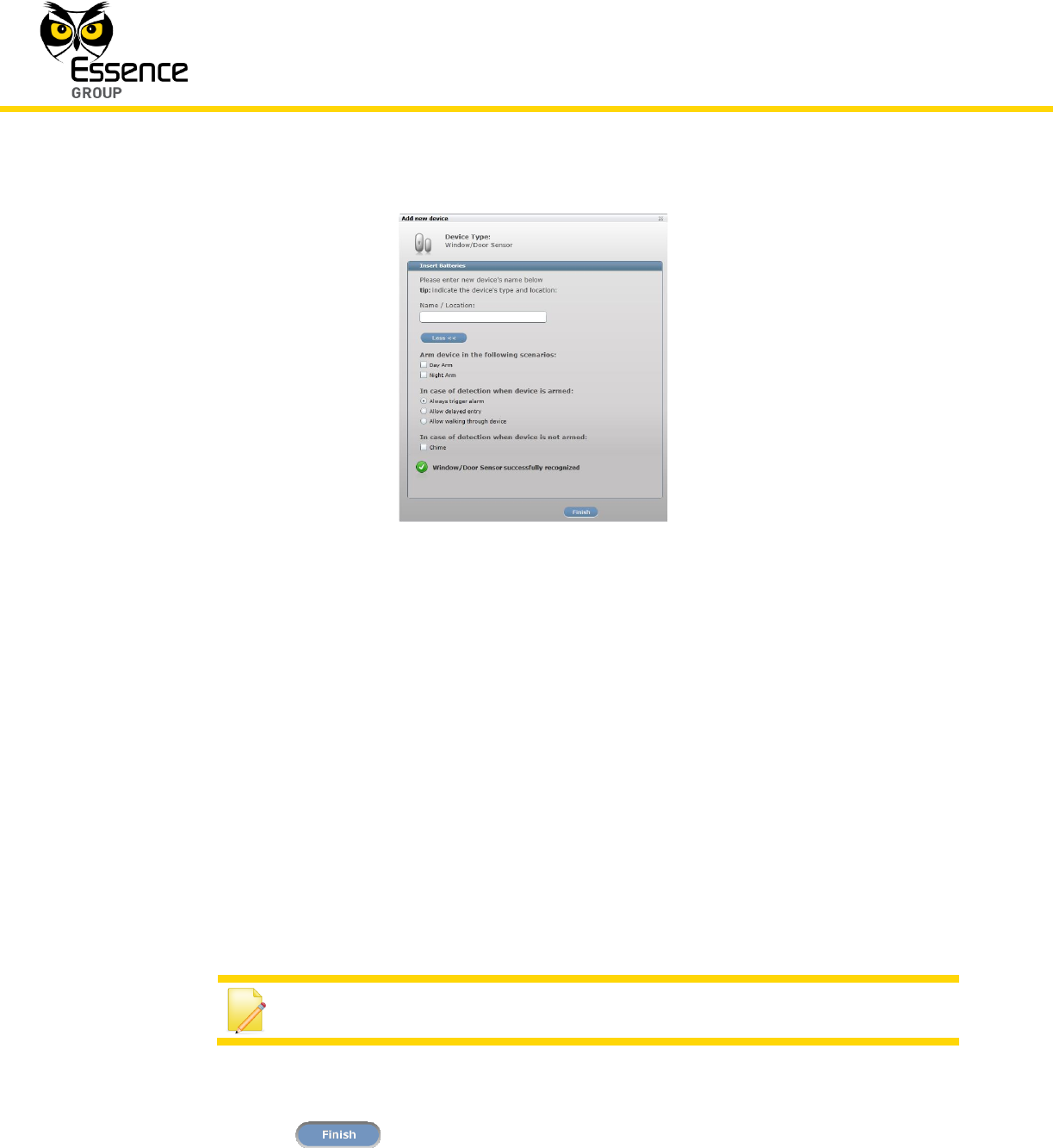
6. An Add New Device (Window/Door Sensor) window will pop-up and its timer will start
running.
Figure 86: Add Magnetic Sensor Window
7. Verify that the Device Type is Window/Door Sensor.
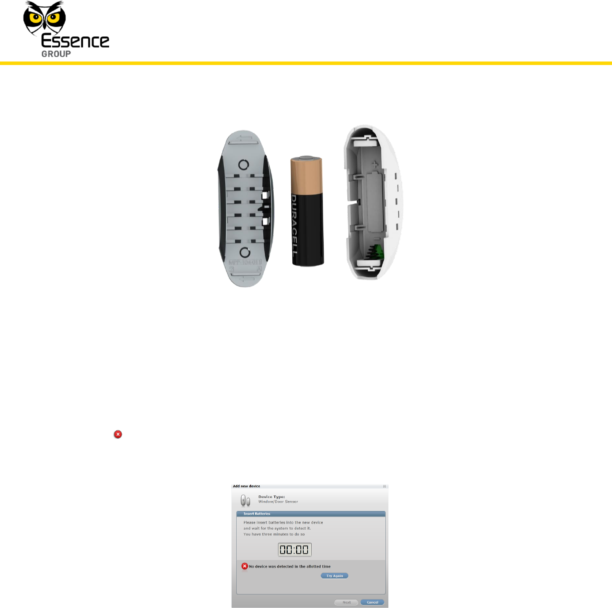
8. The down-counter provides a time-frame of three (3) minutes within which the battery
should be installed, as demonstrated in Figure 87 below (the pole as marked within the
device body), to power-up the Magnetic Sensor.
Verify battery polarity match to marking within the unit body.
Note: In case the installation of the batteries could not be accomplished
within the three (3) minutes period, it is possible to restart the process by
applying step 2 (on page 118) and onwards again.
Installation of the We.R™ System
120
We.R™ System User Guide
Figure 87: Inserting a Battery into the Transmitter Unit
9. The insertion of the battery into the Magnetic Sensor triggers a handshake process in
which the Magnetic Sensor communicates with the CCU to inform it of its presence and the
CCU add it to its peripherals’ inventory.
10. If the CCU did not detect the new Magnetic Sensor within this time-frame, the following
error ( ) message will appear within the Add New Device window:
Figure 88: Add New Magnetic Sensor Timeout Error Message
Installation of the We.R™ System
We.R™ System User Guide
121
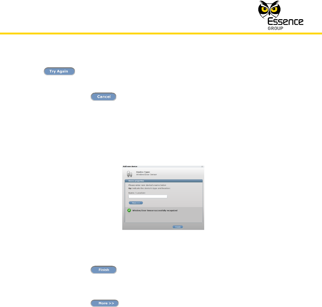
In such a case, it is possible to re-initiate the Add New Device process by clicking over the
button.
Clicking over the button will terminate the Add New Device process.
11. If the new Magnetic Sensor was properly detected by the CCU within this time-frame, the
counter will freeze and a Device Properties sub-window will appear within the Add New
Device window, where the Magnetic Sensor’s system name/location needs to be typed-in.
Figure 89: Add New Magnetic Sensor Device Properties
Clicking over the button will end the Add New Device process while the new
Magnetic Sensor is added onto the system configuration.
12. Clicking over the button will enlarge this sub-window for further possible
definitions of the Magnetic Sensor’s operation modes.
Installation of the We.R™ System
122
We.R™ System User Guide
Figure 90: Add New Magnetic Sensor Device Properties
In the case of a Magnetic Sensor these definitions include:
Magnetic Sensor arming scenarios
Armed Magnetic Sensor response
Unarmed Magnetic Sensor response
These details may be added or edited later, by a Master User, from within the We.R™ Web
Application’s Devices page.
Note: Paragraph 4 below discuss details of such definitions.
Clicking over the button will end the Add New Device process while the new
Magnetic Sensor is added onto the system configuration with more detailed definitions.

Installation of the We.R™ System
We.R™ System User Guide
123
13. You may verify that the Magnetic Sensor (MGL) was properly added by checking the details
of the We.R™ Web Application’s Devices page.
Note: Advanced Configuration of the Magnetic Sensor can be found in
paragraph 4.5.4 below.
3.8.4. Testing the Magnetic Sensor
To verify proper operation of the Magnetic Sensor simply open and close the window/door and
watch the Magnetic Sensor’s LED which should turn red for open window/door or green for
closed window/door.
3.9. The Indoor Siren (SRN) – ES800SRN
The Indoor Siren is a battery operated, wireless, passive, powerful siren for indoor alarm
applications.
Within the We.R™ system, the Indoor Siren also serves the purpose of a door bell.
Accessories available for the Indoor Siren:
Double-sided adhesive tape.
It features:
Battery-operated, wireless, powerful siren for explicit alarm indication
Emits more than 85dBA sound at 1 meter
Adjustable volume level
Dual purpose – may also be used as a door bell (chime)
Wall Mount with double sided tape or screws

Installation of the We.R™ System
124
We.R™ System User Guide
Figure 91: The Indoor Siren
Uses four (4) standard AA-size Alkaline batteries
Long operation – up to 24 months
Tamper Alarm – when the unit is detached from its base
3.9.1. The Indoor Siren Function
The Indoor Siren has two (2) functions:
1. Indoor siren for burglary events.
2. System’s doorbell when used in conjunction with the Wireless Access Control Tag Reader
(see paragraph 3.10. below).
Installation of the We.R™ System
We.R™ System User Guide
125
3.9.2. Installing the Siren
The Indoor Siren is designed be mounted on a vertical wall using the mounting base.
Figure 92: Releasing the Indoor Siren Mounting Base
The mounting base should be disassembled from the Indoor Siren body, as demonstrated in
Figure 92 above, and attached to the wall either by the double-sided tape (pre-attached to the
base) or using screws as demonstrated in Figure 93 below.
Slightly press on the mounting base’s tab and slide it in the tabs direction to release it from the
Indoor Siren body.
3.9.2.1. Siren Positioning Recommendations
For optimal surveillance, the following factors must be taken into consideration when selecting
the Indoor Siren mounting position:
Installation of the We.R™ System
126
We.R™ System User Guide
A flat vertical wall surface.
Attach the Siren to a surface that is clean, dry, flat and smooth.
Location should be selected for best sound spreading around the house.
The mounting base includes three (3) wide punch-outs to allow maximum flexibility of
installation.
Figure 93: Indoor Siren Mounting Base with Screws
Note: The Indoor Siren should always be installed with the latch tab
pointing down.
3
2
1

Installation of the We.R™ System
We.R™ System User Guide
127
3.9.2.2. Installing with Screws
1. Release the Indoor Siren mounting base by lifting the tab and sliding the base in the tab’s
direction as demonstrated in Figure 93 above.
2. Use a flat screwdriver to remove the punch-outs (see Figure 93 above).
3. Place and hold the base on the desired mounting location and mark the drilling locations
(the above-mentioned punch-outs).
4. Drill the holes; insert three (3) dowels if needed, place the base over them and screw in the
three (3) screws.
3.9.2.3. Installing with Pre-attached Double-side Tape
1. Release the Indoor Siren mounting base (above Figure 92).
2. Peel the tapes’ protective covers.
3. Attach the mounting base to its designated location while applying slight pressure.
4. Slide the Indoor Siren into the mounting base.
3.9.2.4. Dismounting the Indoor Siren
For dismounting Siren from its designated installation site (i.e. in case of battery replacement):
1. Press over the tab
2. Slide the Indoor Siren body upwards as demonstrated in Figure 120 below.
Installation of the We.R™ System
128
We.R™ System User Guide
Figure 94: Dismounting the Indoor Siren
3.9.3. Adding the Indoor Siren to the We.R™ System
The Siren need to be functionally added to the system following the above described physical
installation procedure.
The addition of the Indoor Siren is a standard Add Device procedure performed as follows:
Installation of the We.R™ System
We.R™ System User Guide
129
Note: You may also want to refer to paragraph 5.1 below to get acquainted
with the process of installing/replacing a battery in the Indoor Siren.
1. Prepare four (4) AA-size Alkaline batteries required to power the Siren.
2. Activate the We.R™ Web Application.
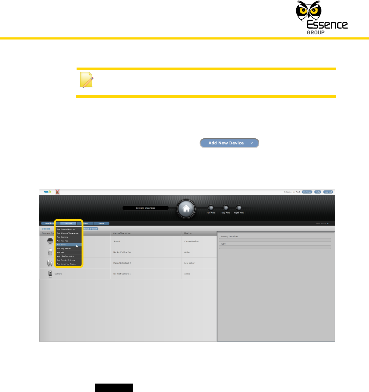
3. Select the Devices page (tab) and click over the button.
4. A roll-down selection menu will open.
Figure 95: Add Siren Device Utilizing Web Application
5. Click over the _Add Siren_ option of the menu as illustrated in Figure 95 above:
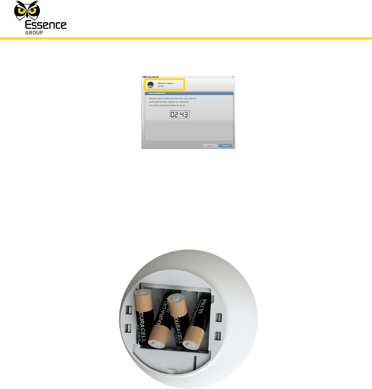
6. An Add New Device (Siren) window will pop-up and its timer will start running.
Installation of the We.R™ System
130
We.R™ System User Guide
Figure 96: Add Indoor Siren Window
7. Verify that the Device Type is Siren.
8. The down-counter provides a time-frame of three (3) minutes within which the batteries
should be installed to power-up the Siren, as demonstrated in Figure 97 below:
Figure 97: Inserting the Batteries into the Siren
Installation of the We.R™ System
We.R™ System User Guide
131
Note: The Siren will double-beep following the insertion of the first two (2)
consecutive batteries to indicate proper power-up sequence.
Verify batteries polarity to match marking within the batteries’ compartment.
Note: In case the installation of the batteries could not be accomplished
within the three (3) minutes period, it is possible to restart the process by
applying step 2 (on page 129) and onwards again.
9. The insertion of batteries into the Siren triggers a handshake process in which the Siren
communicates with the CCU to inform it of its presence and the CCU add it to its
peripherals’ inventory.
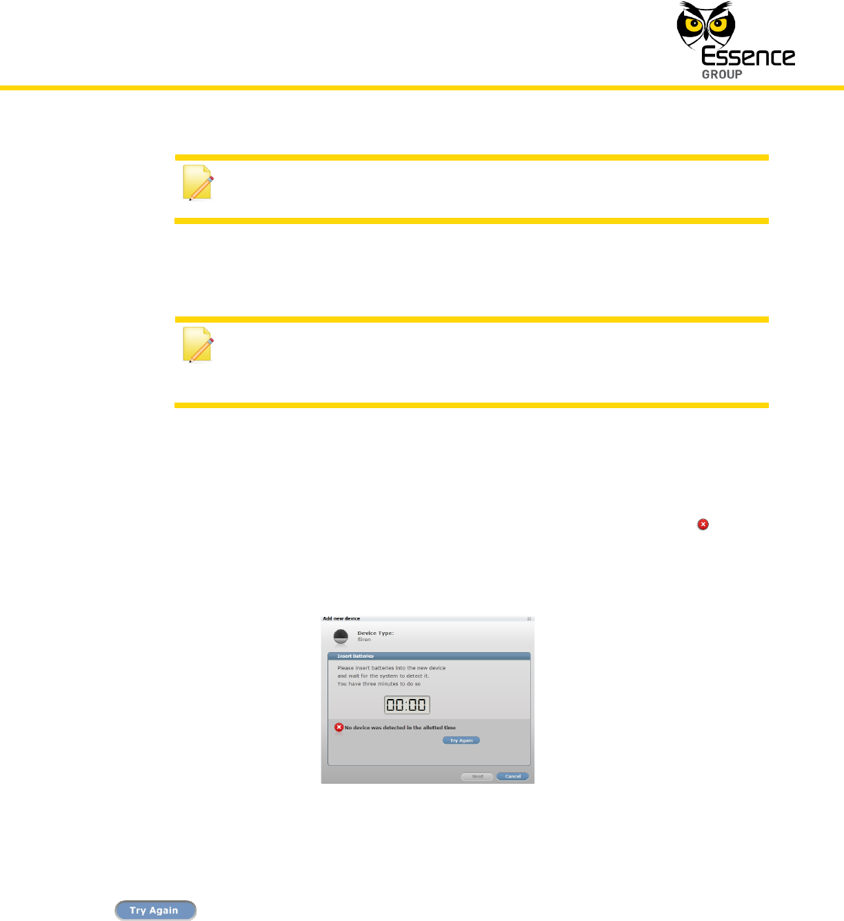
10. If the CCU did not detect the new Siren within this time-frame, the following error ( )
message will appear within the Add New Device window:
Figure 98: Add New Siren Timeout Error Message
In such a case, it is possible to re-initiate the Add New Device process by clicking over the
button.