Essence Security ES800UT Universal transmitter User Manual We R System
Essence Security International ltd. Universal transmitter We R System
Contents
- 1. User_Guide_part1
- 2. User_Guide_part2
- 3. User_Guide_part3
- 4. User_Guide_part7
- 5. User_Guide_part8
User_Guide_part2
Installation of the We.R™ System
We.R™ System User Guide
29
3. Installation of the We.R™ System
3.1. Prerequisites
Prior to the installation and setup of the We.R™ system, the following items need to be
prepared:
This document is best read with Adobe Acrobat Reader® version 10.0 (or higher),
available for free download at: http://get.adobe.com/reader/.
An electronic format (PDF) version of this manual is available, for free download, at:
http://www.essence-grp.com/pages/WeR/WeRFullUserGuide.
AA-size Alkaline batteries for the kit components (10 for the standard kit).
Notes: More batteries might be needed in case additional components
were purchased.
Special batteries: the Central Control Unit’s backup battery and the
Remote Control Unit’s coin-battery are included in the kit.
A personal computer (PC) with internet access and up-to-date browser application
software (Microsoft™ Internet Explorer® 7 or higher, Firefox® 4 or higher, Google’s
Chrome™ browser).
The Microsoft® Silverlight™ web application framework should also be installed on the
PC. It is available for free download from: http://silverlight.net.
The Service Provider’s web server address for the We.R™ Web Application software
(provided by the We.R™ distributor/Service Provider).
If cellular communication is to be used – a SIM-card provided by the distributor or
purchased from a Service Provider.
Notes: Distributor (or Service Provider) of the SIM-card should also provide
a 4-digit APN code for mobile access. In special cases more APN data (see
details on page 43) might be needed.
Installation of the We.R™ System
30
We.R™ System User Guide
A smartphone (optional) for remote system management.
A small screwdriver.
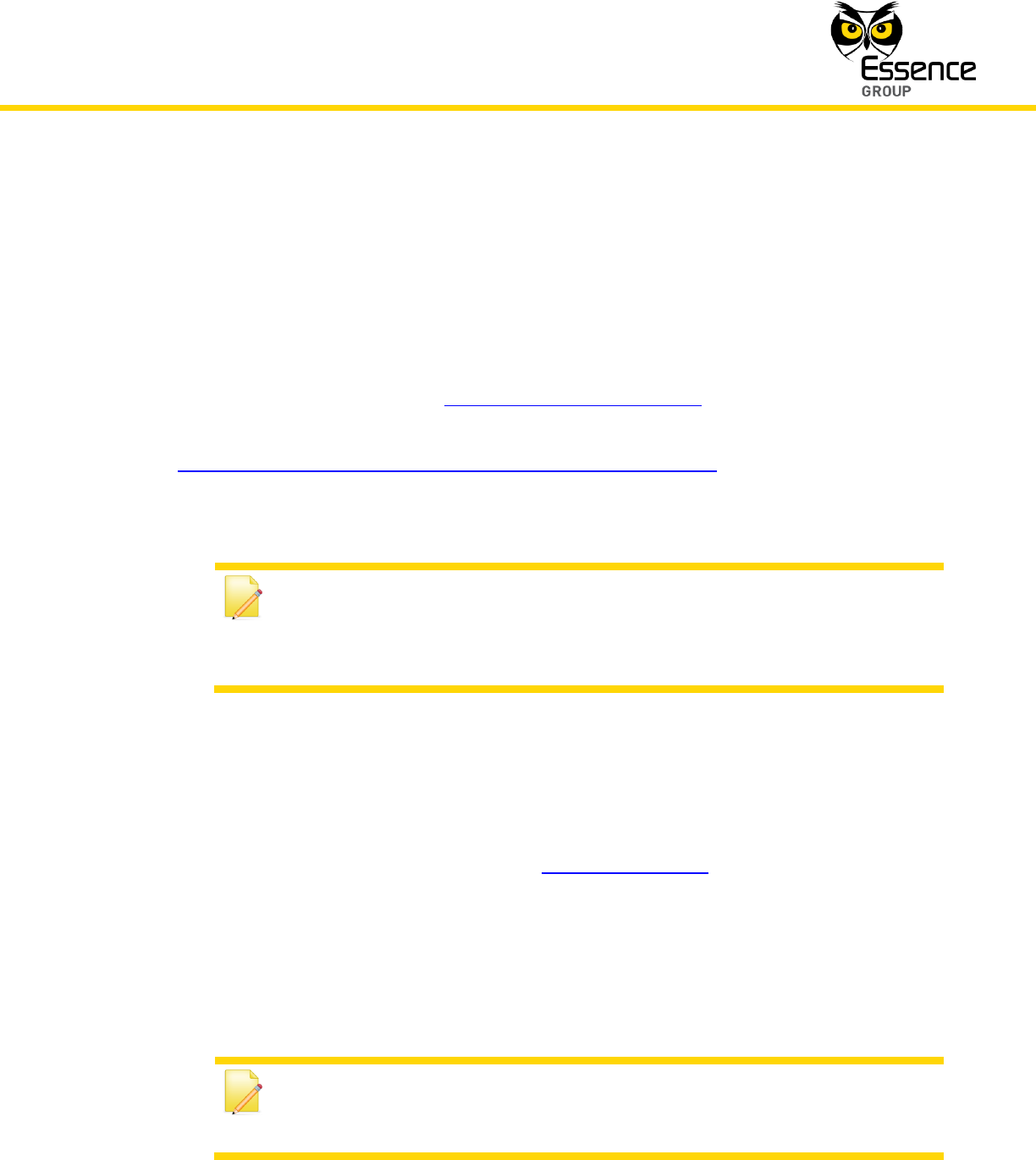
The Central Control Unit’s identification serial number should be registered prior to the
installation process.
Stickers with the serial number can be found inside the battery/SIM-card cavity and
under the Central Control Unit’s base as illustrated in Figure 4 below.
Figure 4: CCU Serial Number Locations
Note: You may also want to register this serial number in Appendix H
Owner’s Records of this User Guide (page 301) where important data of
your system is aggregated for future reference.
This chapter of Installation of the We.R™ System provides information about each and every
component of the system including its installation, power-up, configuration, integration into the
system and operation.
Installation of the We.R™ System
We.R™ System User Guide
31
It is arranged in the exact same sequence the system needs to be built-up, including the steps
of software installation and registration. Therefore, it is advised to follow this sequence to
ensure properly functioning system.
The We.R™ system is based on independent components described below.
The order of presenting these components is the recommended order of their installation.
Note: Except for the Central Control Unit, not all the below-mentioned
components must be installed for a functional alarm system.
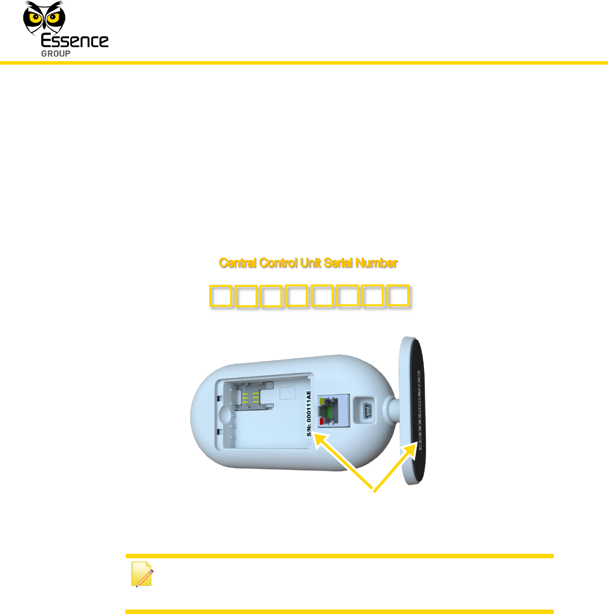
3.2. The Central Control Unit – ES8000CP
The center-piece of the We.R™ system is the Central Control Unit (CCU or CP).
Figure 5: The Central Control Unit

Installation of the We.R™ System
32
We.R™ System User Guide
It is a two-way, wireless Central Control Unit comprising the main element of the We.R™
system.
3.2.1. The Central Control Unit Function
The Central Control Unit (CCU) is responsible for wireless communication with the array of
We.R™ sensors/detectors, remote access and interface devices internally (within the premises),
through the RF communication channel, as well as communications with the external cloud
computing services system, through the Internet or cellular channels.
The CCU incorporates the following functions:
Two-way secured communications (AES encrypted) with the We.R™ system's
peripherals.
Plug-and-Play Internet (IP) connectivity.
Optional, built-in GSM/GPRS/EDGE quad-band (850/900/1800/1900MHz) modem.
Supporting transfer of high quality, high resolution, color pictures.
Traffic Usage – Simple Event/Command: 200-300 Bytes (text), Streaming Event: 200-
250 Kbytes (25 Frames).
Supports automatic over-the-air software upgrade programming and configuration.
Rechargeable backup battery.
3.2.2. Installing the Central Control Unit
As mentioned in the above paragraph 2.3.3, prior to the installation of the CCU the following
items must be prepared:
The CCU’s backup battery.
A PC connected to the Internet and running browser application software.
The LAN cable (in case the Internet is to be used as external CCU communication
channel).
The SIM-card provided by the Service Provider (in case the CCU is to be
communicating via the cellular channel) with its 4-digit APN code (other APN data
might be required too, see details on page 43).
A smartphone (optional).
Installation of the We.R™ System
We.R™ System User Guide
33
Registration of the CCU’s serial number (see page 30) should also be completed.
3.2.2.1. CCU Positioning Recommendations
The CCU should be installed on:
A flat surface.
In a central home/office location with:
Unshielded adequate cellular coverage (if cellular communication is to be used).
Close to an Internet connection outlet (modem/router connection, if Internet
communication is to be used).
The CCU must be activated and the system must be registered with the Service Provider (or
the distributer) to enable its proper operation.
The following need to be executed for the setup and activation of the CCU:
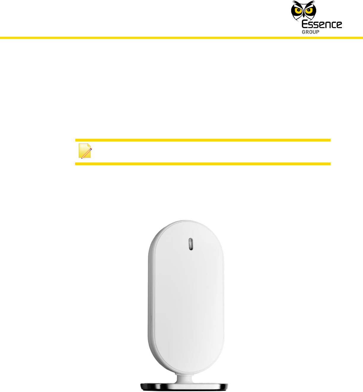
1. Remove the back cover of the CCU to reveal the battery/SIM-card compartment.
2. In case cellular is intended to be used for external communication – insert the SIM-card,
with its contacts facing down, as illustrated in Figure 6 below.
Note: Refer to the graphic representation of the SIM-card engraved onto
the plastic bottom of the cavity, next to the card’s designated location.
Figure 6: Insertion of the SIM-card
Installation of the We.R™ System
34
We.R™ System User Guide
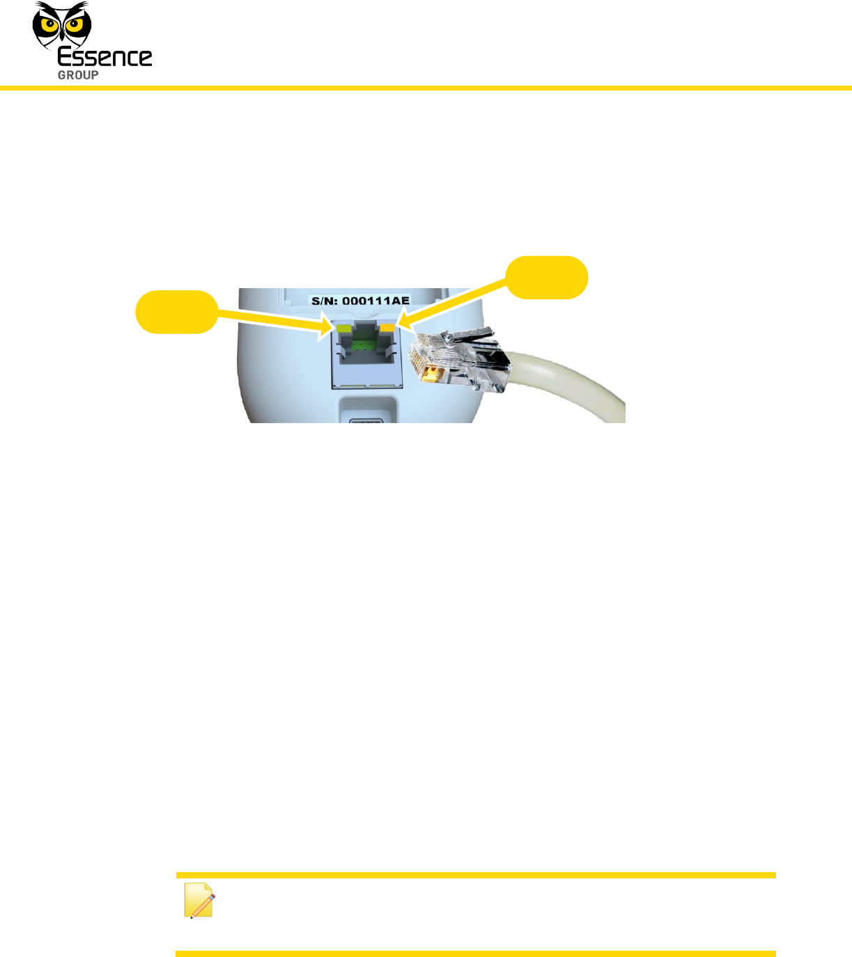
3. In case the Internet is intend to be used as the primary external communication channel:
Plug the LAN cable into the RJ45 socket on the back panel of the CCU and its other end
into a network socket (in the Internet router or modem).
Figure 7: Insertion of LAN Cable into the CCU Socket
The CCU back panel LAN (RJ45) socket provides two (2) LED status indications, active in
accordance with the IEEE 802.3u standard, as a convenient means of determining the
mode of operation of the network:
i. LED1 (Green) is the Link Activity LED.
It will lit steady once the network transceiver detects a valid link and will blink upon link
activity (transmit/receive).
ii. LED2 (Amber) is the Link Speed LED.
It will turn ON once the detected link speed is 100Mbit/Sec and will turn OFF once the
detected link speed is 10Mbit/Sec. A blinking LED2 indicates communication collision.
4. If there is no Internet connection available or the LAN cable is not connected, the SIM-card
will be used as the primary connection channel between the We.R™ system and the We.R™
server.
Note: If both the SIM-card and the LAN cable are installed, the Internet will
be the primary communication method and the cellular channel will be used
for backup.
LED 1
LED 2
Installation of the We.R™ System
We.R™ System User Guide
35
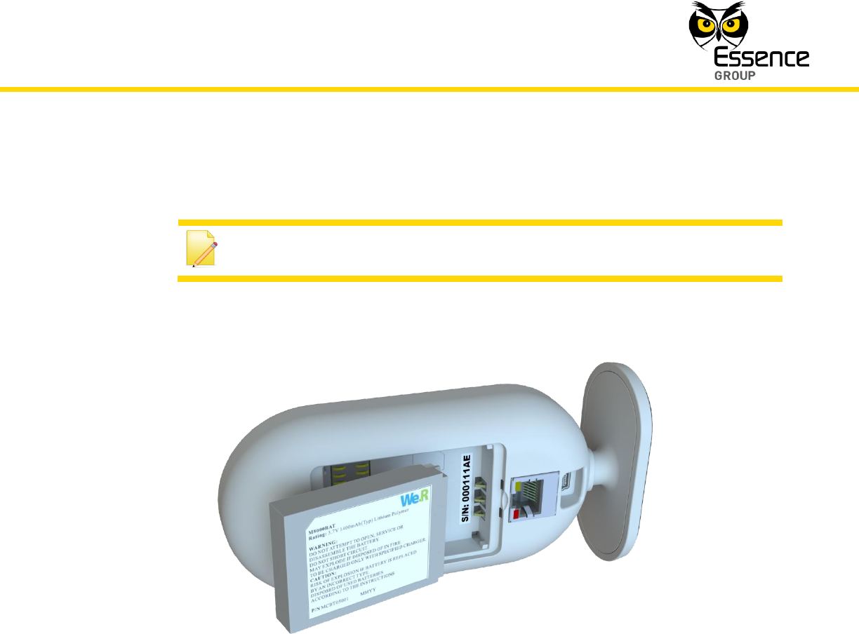
5. Insert the backup battery into the battery cavity, above the SIM-card.
Note: Battery’s label should be facing up and the battery’s contacts –
aiming towards the base of the CCU.
Figure 8: Insertion of the Backup Battery
6. Return the battery cover back to place.
7. Plug the Power Supply's cable into the mini-USB™ connector on the back of the CCU.
8. Plug the adapter’s cube into an electric power outlet socket.
The LED on the front panel of the Central Control Unit should light with orange color.
9. Place the CCU in its designated location.
10. Wait for the CCU’s front panel LED to switch from orange to green color before continuing
to sub-paragraph 3.2.3 below.
Installation of the We.R™ System
36
We.R™ System User Guide
Notes: The LED switching from orange to green indicates that the CCU is
properly active. It takes approximately 5 minutes for the LED to switch.
The Central Control Unit is now ready for the next step of registration and setup.
Note: The initial registration is a web-only procedure and therefore could be
exercised utilizing the Web Application only (cannot be done with the
Mobile Application).
3.2.3. Activating the Central Control Unit
Notes: This paragraph details the initial registration process of the system,
utilizing the We.R™ Web Application software. It is a one-time procedure
exercised as part of the activation of the system’s Central Control Unit. The
We.R™ Web Application is a comprehensive software package dealing not
only with this initial registration procedure but with all aspects of
administrating the We.R™ system (Status reports, peripheral devices’
add/remove and setup, events history, etc.). It is, therefore, recommended
to read paragraph 3.3 The We.R™ Web Application below prior to the
activation of the CCU.
Activation of the CCU begins with registration of the We.R™ system with the Service Provider’s
web server. Besides introducing the We.R™ system to the server, via the cloud, it also allows
the definition of method of mobile communications.
Note: Typing-in the login information (email address and password) and
clicking over the button will be the only action required for
subsequent logging onto the We.R™ Web Application.
Installation of the We.R™ System
We.R™ System User Guide
37
The registration procedure is done via the We.R™ Web Application as follows:
1. Utilizing PC running web browser software, go to the We.R™ Web Application by entering
the Service Providers’ server address.
Note: You may want to create a short-cut link for this address for ease of
future access to the Web Application.
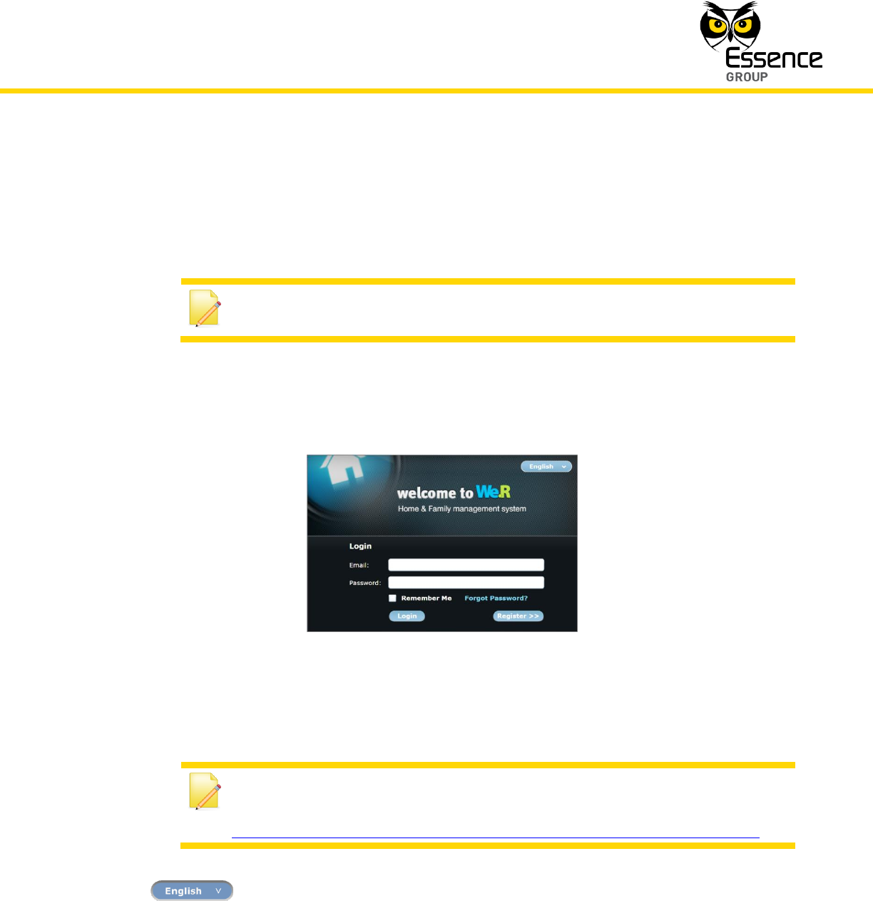
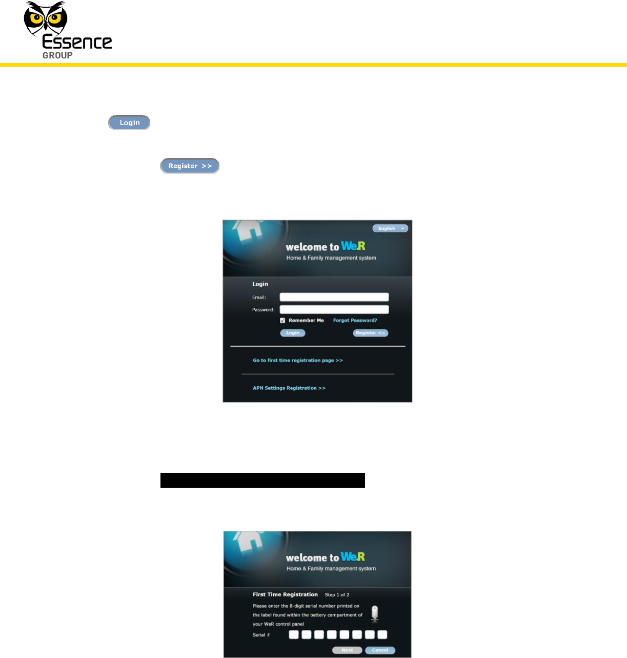
2. The Login window will pop-up:
Figure 9: The We.R™ Web Application Login Window
Note: If prompted, install the Microsoft® Silverlight™ web application
framework available for free download at:
http://www.microsoft.com/getsilverlight/Get-Started/Install/Default.aspx.
The button allows selection of the interfacing language.
For the initial registration procedure no information need to be typed into the Email and
Password fields.
Installation of the We.R™ System
38
We.R™ System User Guide
The button will be will be used for subsequent logging into the We.R™ Web
Application.
3. Click over the button only.
A roll-down menu will be added at the bottom of the Login window:
Figure 10: The Login Window with the Roll-down Menu
11. Click over the _Go to first time registration page >>_ option.
The First Time Registration (Step 1 of 2) window will pop-up:
Figure 11: CCU First Time Registration Window
Installation of the We.R™ System
We.R™ System User Guide
39
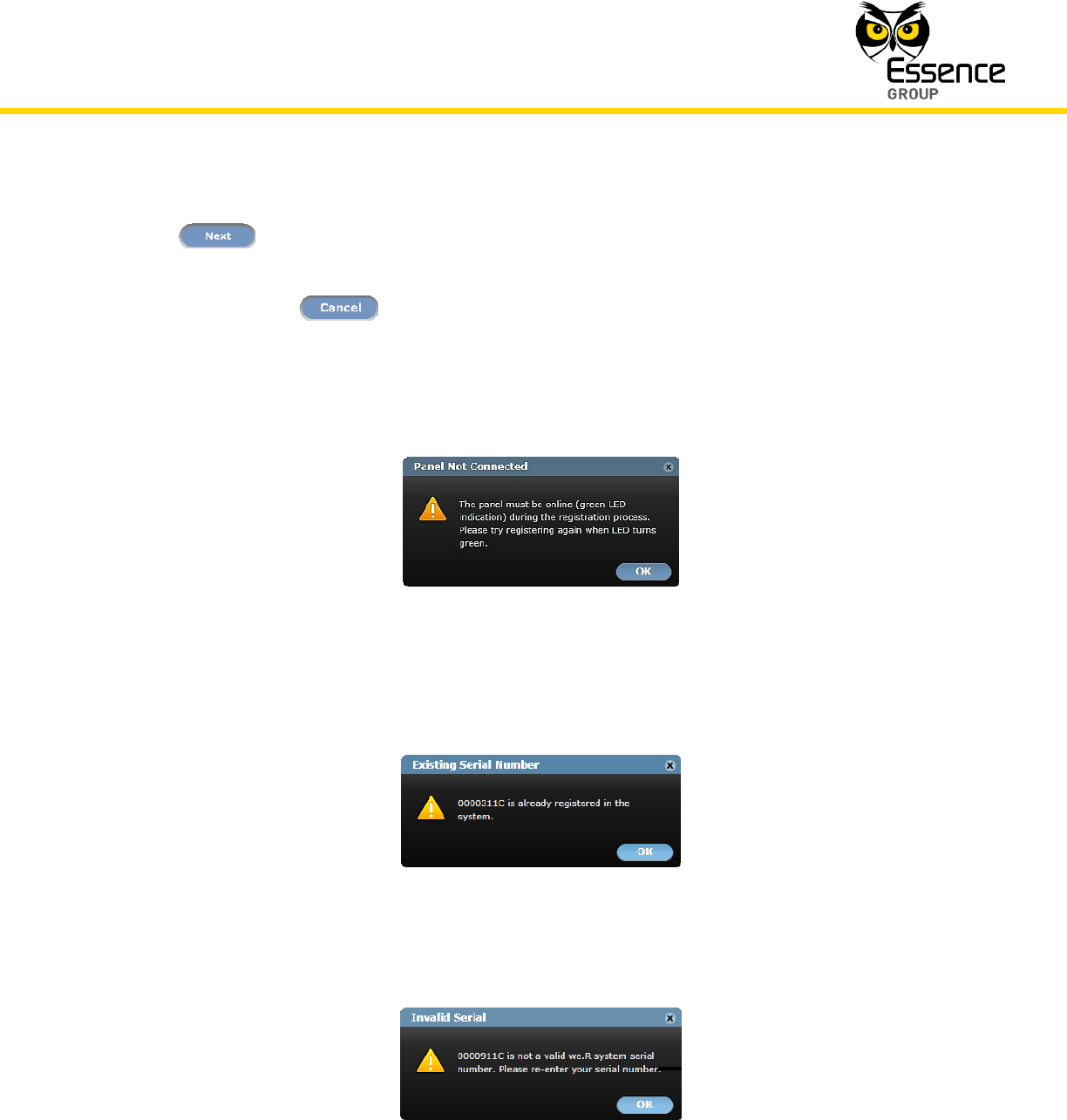
12. Type-in the 8-digits serial number recorded on page 30 (and Appendix H) and click over
the button. The Web Application software performs, at this point in time, a
validation procedure to ensure the number typed is correct.
Clicking over the button will take you back to the Login window (see above Figure
10).
In case the CCU was previously incompletely registered and this procedure started before
the front CCU’s LED switched to green; a Panel Not Connected error message will pop-up:
Figure 12: Panel Not Connected Error Message
In case this serial number was already registered with the system; an Existing Serial
Number error message will pop-up:
Figure 13: Existing Serial Number Error Message
In case the serial number typed was invalid; an Invalid Serial error message will pop-up:
Figure 14: Invalid Serial Error Message
Installation of the We.R™ System
40
We.R™ System User Guide
In all the above error cases, clicking over the button will take you back to the Login
window (see above Figure 10).
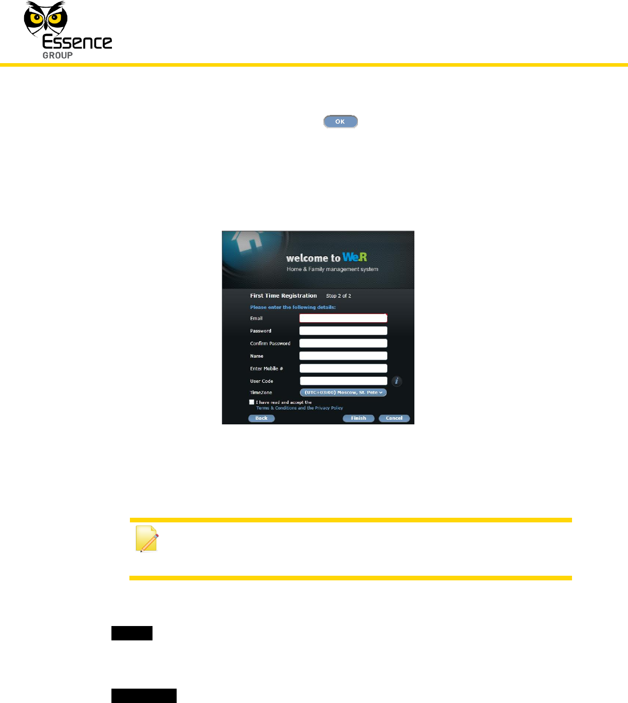
13. In case the number typed is valid, the First Time Registration (Step 2 of 2) window will pop-
up:
Figure 15: First Time Registration Step 2 Window
Note: You may want to record the following registration details
to Appendix H Owner’s Records of this guide (page 301) where important
data of your system is gathered for future reference.
14. Type-in your personal details as follows:
i. _Email_ – Address where system’s messages and notifications will be sent to via
email.
ii. This address will also be used for subsequent login (see above Figure 9).
iii. _Password_ – Required for safe login.
Installation of the We.R™ System
We.R™ System User Guide
41
Note: The login password is case sensitive and must have a minimum of six
(6) alphanumeric characters.
This password need to be confirmed (re-typed) in the next field – _Confirm
Password_.
The information provided for the above fields will also be used as key-codes for
subsequent accesses to the Web Application (see above Figure 9).
iv. _Name_ – The User Name you will be identified with in the system. This is a case-
sensitive, alphanumeric characters’ field.
v. _Enter Mobile #_ – Type-in your mobile telephone number.
This data is for information records only (not used at this point in time).
Use digits only in international telephone number format (for example: 972522728110).
vi. _User Code_ – For the We.R™ Mobile Application to be installed on a later stage on
the smartphone, you are required to initiate a four (4) digits user identification code (an
extra password).
vii. _TimeZone_ – Select your time-zone from the roll-down menu, to synchronize the
system clock for correct email messages and notifications time-stamps.
Note: The Web Application servers are always set to zero (0) UTC time
zone (Zulu time).
15. Acknowledge your acceptance of the Terms & Conditions of usage for this software by
marking the check-box at the bottom-left side of the window.
A copy of this terms and conditions is attached to this guide as Appendix B End User
License Agreement (EULA).
It is also accessible via the link _Terms & Conditions and the Privacy Policy_.
16. Clicking over the button terminates the process (upon completion).
Installation of the We.R™ System
42
We.R™ System User Guide
Clicking over the button, throughout the above process, bounces you back to the
First Time Registration Page 1 window (see above Figure 11).
Clicking over the button, throughout the above process, bounces you back to the
Login window (see above Figure 10).
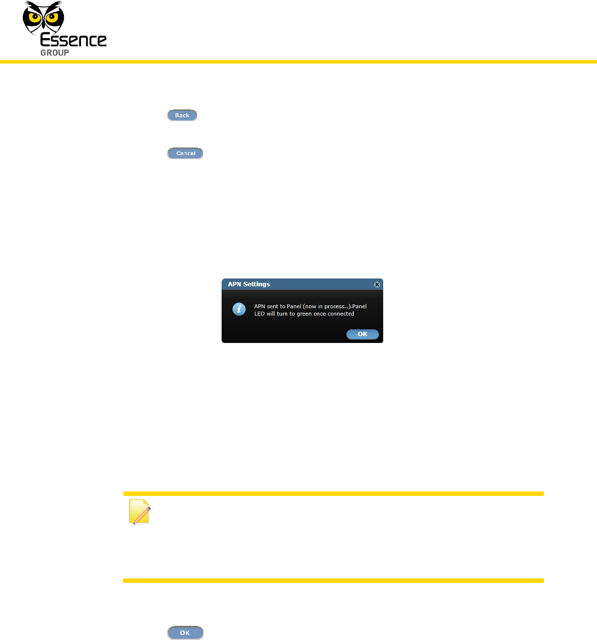
17. If no error detected during the above procedure of entering the initial registration data, the
following confirmation message will pop-up:
Figure 16: Registration Confirmation Message Window
Within a period of approximately 5 minutes, the CCU’s front LED should turn green and the
registration process is concluded.
Notes: If the LED remains orange (does not switch to green), it means that
communication could not be established (verified and registered properly),
usually due to wrong APN data.
Green flashing LED means the CCU is being updated by the Remote
Software Upgrade (RSU) mechanism.
Clicking over the button will close this message window (but the process of
connecting will continue until completed as indicated by the LED switching to green).
Installation of the We.R™ System
We.R™ System User Guide
43
3.2.3.1. Manual Access Point Name Data Registration
In case a problem is encountered during the initial registration procedure, with the Access
Point Name (APN) data; you need to contact the SIM-card’s Cellular Operator/Service Provider
and get all of the APN data.
This data need to be manually typed into the registration data fields.
This is done by clicking over the _APN Settings Registration >>_ menu option of the roll-down
menu added to the Login window (see above Figure 10).
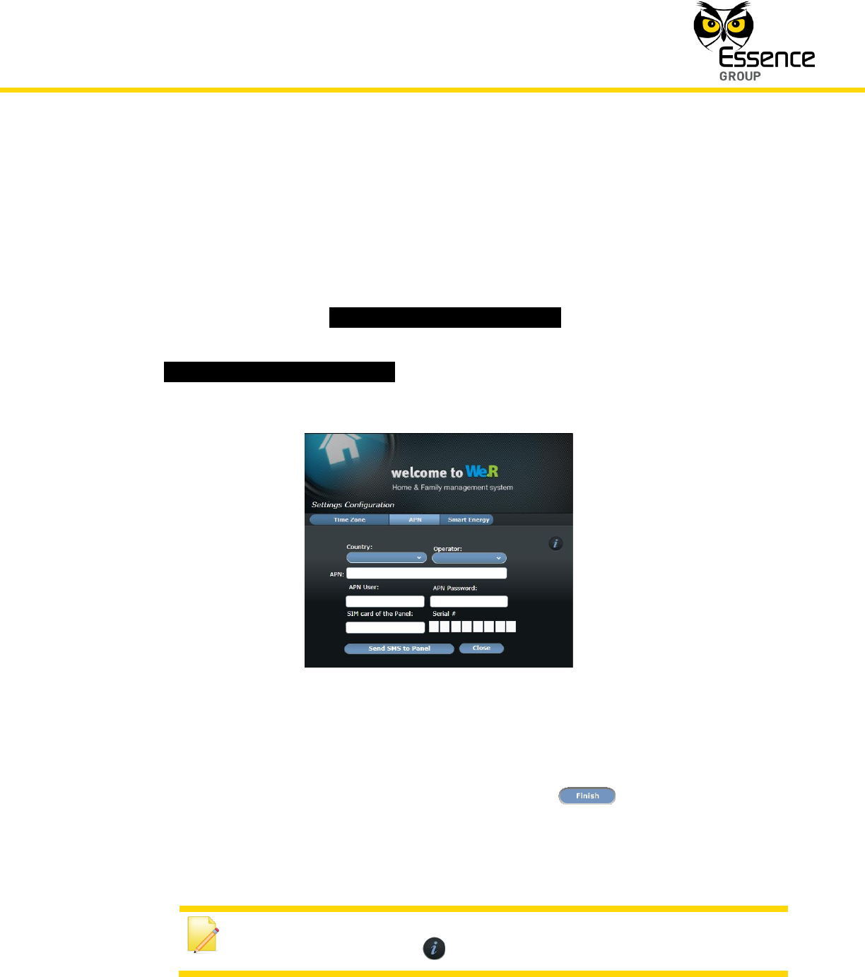
Once the _APN Settings Registration >>_ is clicked over, the APN Settings Configuration
window pops-up:
Figure 17: APN Settings Window
Most market available SIM-card’s APN data is pre-programmed into the We.R™ system and
being updated on a regular basis, therefore:
1. The automatic process executed following the click over the button (see line-
item 14 on page 40) should complete the registration process with no problem.
In case the process does not complete properly (the LED did not turn green):
Note: A short-form explanation regarding this process is also available
online by clicking over the button.
Installation of the We.R™ System
44
We.R™ System User Guide
i. Call your cellular Service Provider and obtain all APN data (APN name, APN user and
APN password).
Note: You may want to record the APN data to Appendix H of this User
Guide where important data of your system is gathered for future reference.
ii. Select the _Country_ and _Operator_ (Cellular Service Provider) from the roll-down
menus in the APN Settings Configuration window (see above Figure 17).
iii. Manually type-in all the APN data retrieved from the Cellular Service Provider.
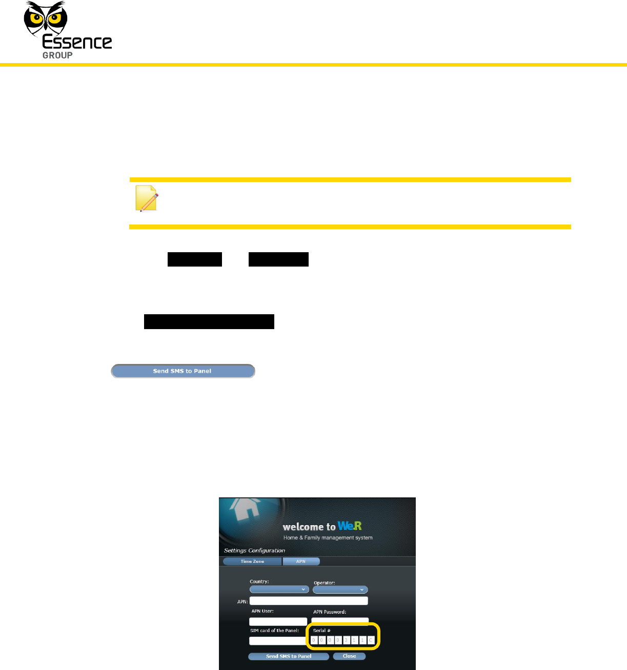
iv. In the _SIM card of the Panel:_ field, type-in the international cellular telephone number
of the SIM-card (digits only, no prefix, for example: 972522728110) and the CCU’s
serial number (see page 30 and Appendix H) and click over the
button.
v. Wait for the front panel LED to turn green (may take up to 15 minutes).
In case the manual entry of APN data is done for a CCU which was already registered
(i.e. upon replacing a faulty SIM-card), the APN Settings Configuration window shown
in the above Figure 17 will pop-up with the CCU’s Serial Number already typed-in (but
greyed-out) as illustrated in Figure 18 below:
Figure 18: APN Settings Window for a Registered CCU

Installation of the We.R™ System
We.R™ System User Guide
45
2. Once the system is registered, it is recommended to add Users before proceeding to the
next step of installation. See details in the below paragraph 3.3.6.4.
3.3. The We.R™ Web Application
The We.R™ Web Application is classic cloud-computing software application based on the
latest RIA (Rich Internet Application) technologies and utilizes Microsoft® Silverlight®
technology. It provides smooth, fast and responsive experience along a set of tools for home
security and management.
The run-time environment for Silverlight® is available as a plug-in for most web browsers based
on the Microsoft® Windows® OS (Operating System). It is available for free download from:
http://www.microsoft.com/getsilverlight/Get-Started/Install/Default.aspx.
Note: The previous paragraph already dealt with the Web Application, with
respect to the first-time system registration only.
It was a one-time procedure exercised as an action item within the process
of the activation/registration of the system’s CCU.
This paragraph details all other aspects of the We.R™ Web Application.
3.3.1. The Web Application Function
The Web Application provides the user with access to the following system functions:
Home monitoring, safety, security and smart home management.
Self-installation and activation via the web.
Dashboard page – Presents:

Installation of the We.R™ System
46
We.R™ System User Guide
System Status,
System Activation,
Device Overviews,
Recent Events,
Look-in via Camera.
Devices page – Manages system devices.
History page – Allows investigation of recent events including video as well as filtering
of the event history log.
Users page – Manage Users (Master User, Standard User).
Central Control Unit Signal Strength Indicator – Displays the GSM signal strength (for
Central Control Units with a SIM-card).
APN Activation – Automatic APN activation. Available for any SIM-card supporting SMS
and data transfer.
Notifications – Tamper, Low battery, Connection Lost, power failure/restore.
Chime – Optional siren feature.
Multilingual support.
3.3.2. Activating the Web Application
Being a classic cloud-computing application, the We.R™ Web Application requires only a PC
with an Internet browser to access and use.
There is no need to download and/or install any software.
3.3.2.1. Prerequisites
The following items need to be prepared before installing the We.R™ Web Application:
A personal computer (PC) with internet access and up-to-date browser application
software (Internet Explorer® 7 or higher, or Firefox® 4 or higher, or Chrome™ browser).
Installation of the We.R™ System
We.R™ System User Guide
47
The Microsoft® Silverlight™ web application framework should also be installed on the
PC. It is available for free download and installation at:
http://www.microsoft.com/getsilverlight/Get-Started/Install/Default.aspx.
The Service Provider’s web address (URL) for the We.R™ Web Application software.
Note: You may want to create a short-cut link for this address for future
ease of access to the Web Application.
A smartphone (optional) for remote system management.
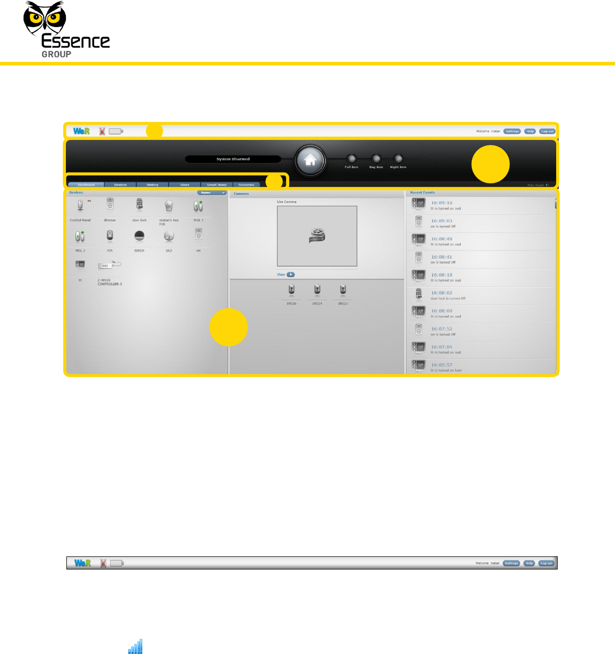
3.3.3. The Web Application Display Structure
The screen of the We.R™ Web Application is divided into functional areas where:
Tool Bar – presents some basic control tools for the We.R™ Web Application.
Status/Activation Bar – For the We.R™ system’s status display and setting of mode of
operation.
Displayed Data Selection Tabs – used to select the type of information displayed.
Data – different data types selected by the tabs, for display and manipulation.
1
2
3
4
4
Installation of the We.R™ System
48
We.R™ System User Guide
Figure 19: The Web Application Display
3.3.4. The Tool Bar
The Tool bar provides access to the global most common Web Application setting tools:
Figure 20: The Tool Bar
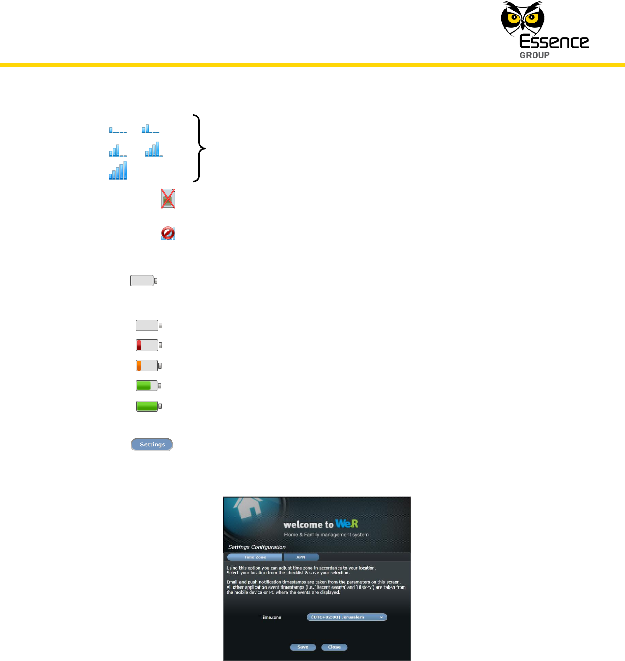
The icon provides information regarding the strength of the CCU’s cellular signal. It
could display:
1
4
2
3
Installation of the We.R™ System
We.R™ System User Guide
49
or or
or or
Signal strength meter indicating the CCU’s cellular
signal strength.
No SIM-card installed in the CCU.
Cellular channel communication lost.
The icon provides information regarding the charge capacity of the CCU backup
battery. It could display:
Battery dead
Battery critical
Battery low
Battery normal
Battery full
The button launches the Settings Configuration window:
Figure 21: The Settings Configuration Window
Installation of the We.R™ System
50
We.R™ System User Guide
This window is a sub-set of the initial registration procedure (see paragraph 3.2.3.
above) which allows (by tab selection):
Re-setting of the Time Zone defined in the initial registration procedure (see
page 41) by selecting it from the roll-down selection menu which opens upon
clicking over the button.
Any change made to the previously defined Time Zone need to be saved by
clicking over the button.
Termination of this activity is done by clicking over the button.
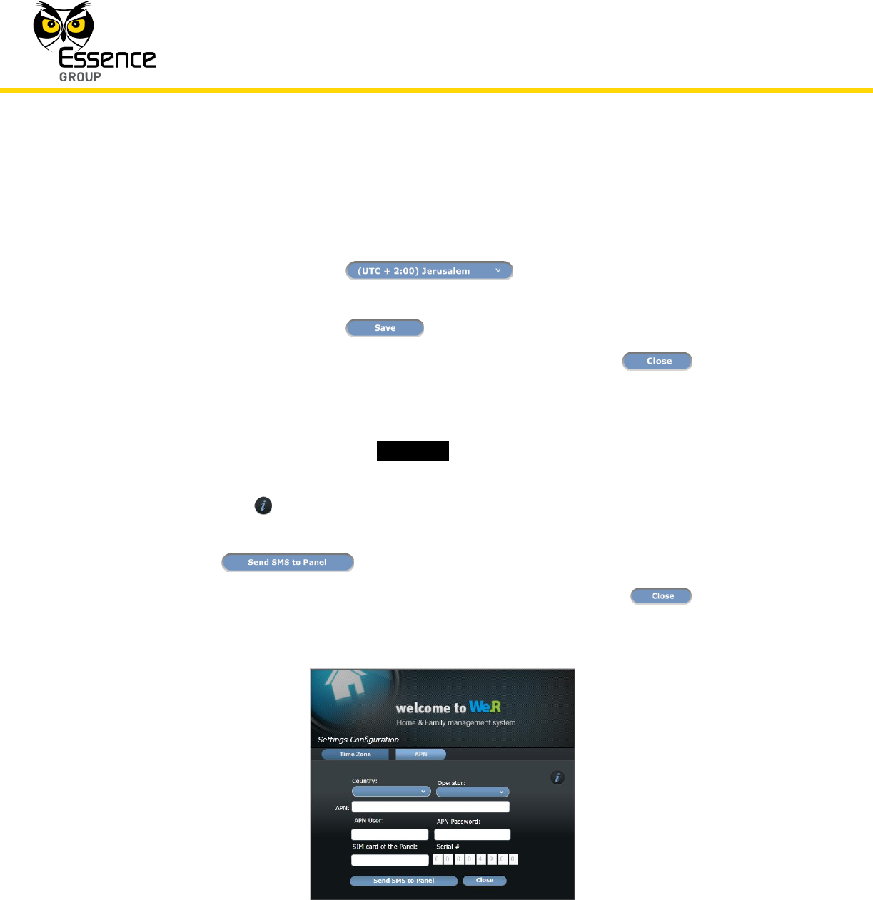
Manual entry of APN data; a similar process to the one described in the
above sub-paragraph 3.2.3.1.
Note that the CCU’s _Serial #_ appears grey and cannot be edited, since we
are dealing, at this point in time, with a formerly registered system.
The button brings up a quick help file for APN data entry.
Following the entry of all APN data, there is a need to click over the
button to transfer the data onto the CCU’s memory.
Termination of this process is done by clicking over the button.
Figure 22: Manual Entry of APN Data Window
Installation of the We.R™ System
We.R™ System User Guide
51
The button opens this We.R™ System User Guide document.
The button logs out of the Web Application and terminates its operation.
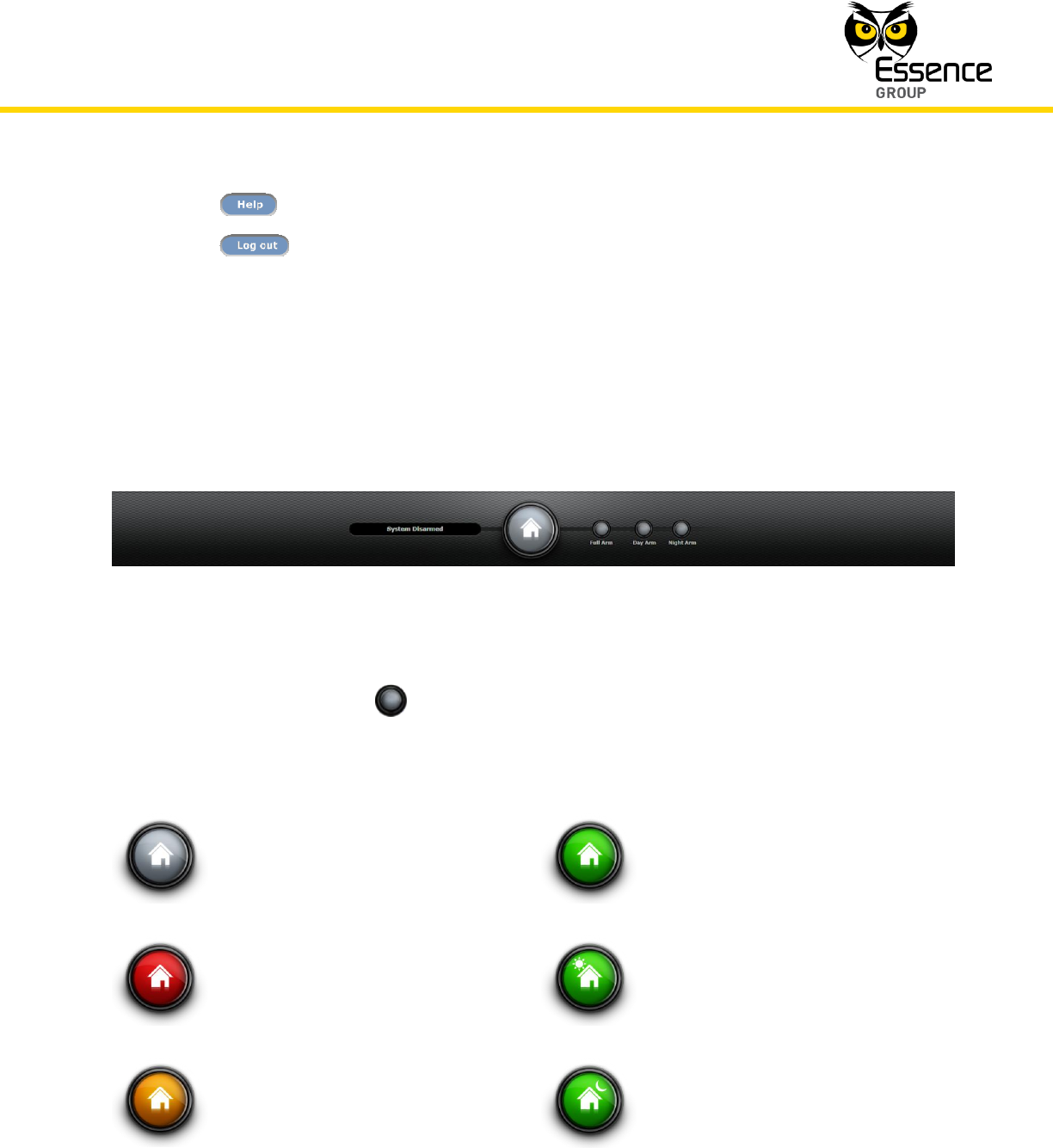
3.3.5. The Status/Activation Bar
The Status/Activation bar provides, at a glance, real-time information about the system status
as well as enabling basic system arming commands.
Figure 23: The Status/Activation Bar
Clicking over any of the three arming buttons will trigger the system into the operation
mode called for (Full Arm, Day Arm or Night Arm).
The system status is reflected by the image and color of the central icon as follows:
(grey)
System Disarmed
(green)
System (fully) Armed
(red)
Burglary Alarm
(green)
System Day Armed
(yellow)
Safety Hazard
(green)
System Night Armed
Installation of the We.R™ System
52
We.R™ System User Guide
The text messages to the left of this icon word-out the meaning of the image on display.
3.3.6. The Data Window
The data window allows in-depth system setup, monitoring and control. The type of data to be
displayed and dealt with is presented over four (4) or six (6) pages (pending the inclusion of a
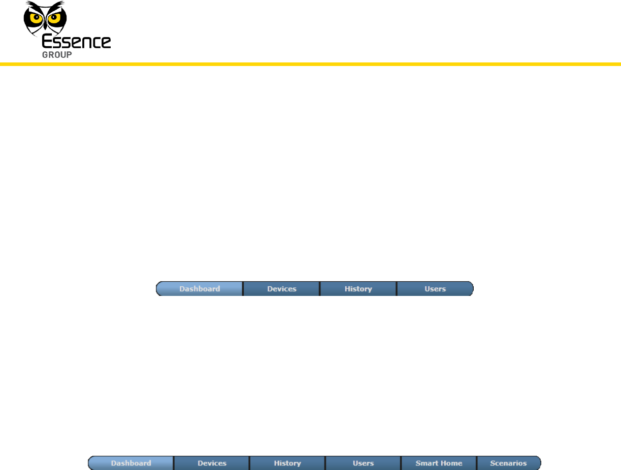
Z-Wave® Controller), selected by a tab bar with the following four (4) basic tab options:
Figure 24: Data Window 4-Tab Bar
In case a Z-Wave® controller (a Smart Home application) is installed, the basic four (4) tab bar
is expanded to include two (2) more tabs dealing with the setup of Z-Wave® devices and their
scenarios of operation.
Figure 25: Data Window 6-Tab Bar
These cases will be discussed within the relevant paragraphs below.
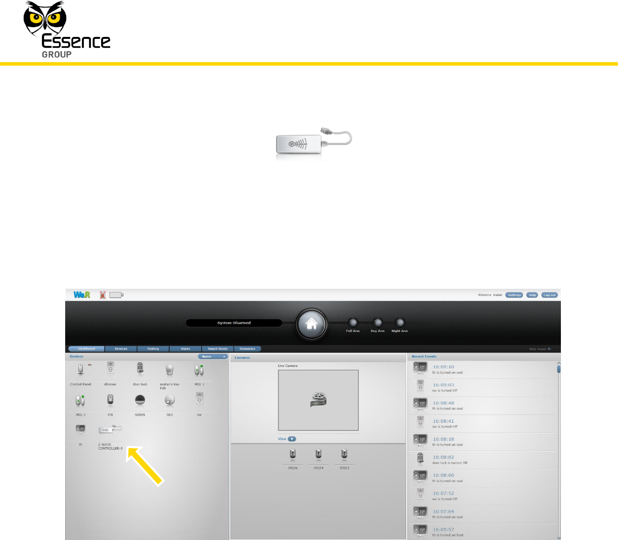
3.3.6.1. The Dashboard Page
The Dashboard page is the main (and default) page of the We.R™ Web Application providing
an at-a-glance overview of the We.R™ system status.
Installation of the We.R™ System
We.R™ System User Guide
53
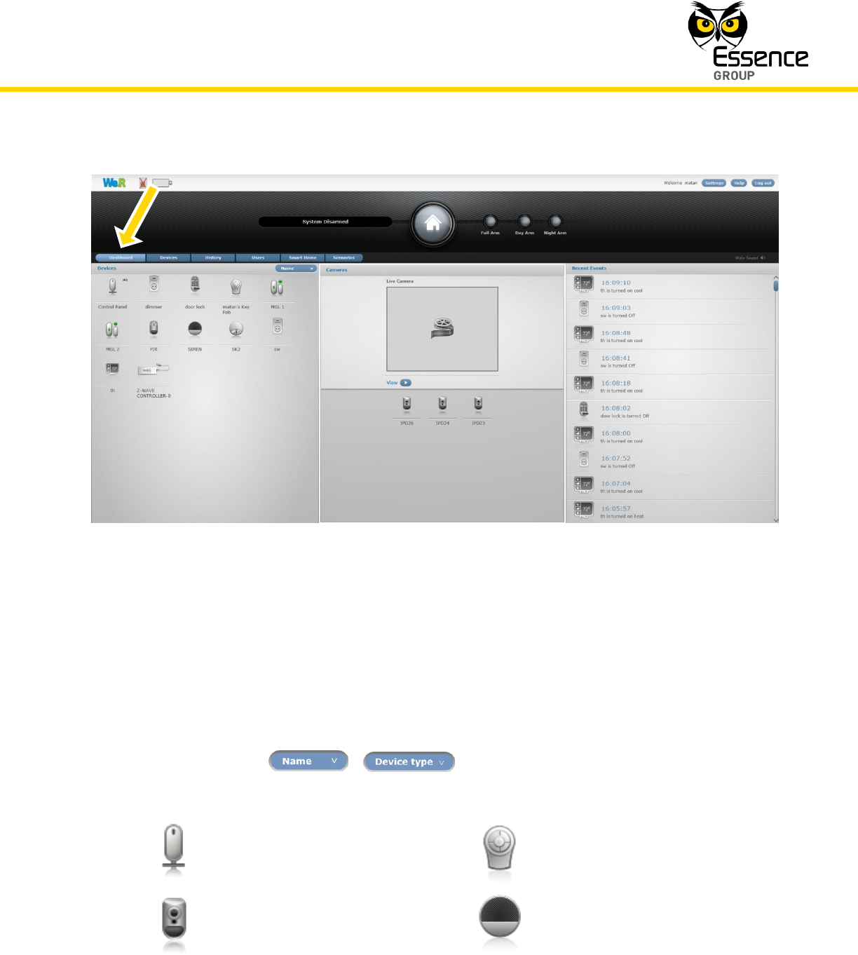
Figure 26: The Dashboard Page
This data window divides into three (3) panes:
The Devices (left) pane – an overview pane graphically (using icons) presenting all
system defined components, their system given name and, sometimes, an additional
sub-icon presenting their event or status information.
System status presentation could be sorted by Device Name or Device Type by
clicking over the / switching button.
The reported items are presented by icon images, within all panes, as follows:
Central Control Unit
Remote Control Unit (KF)
Motion Indoor Photo Detector
Indoor Siren
Installation of the We.R™ System
54
We.R™ System User Guide
Motion Detector
Door/Window Magnetic
Sensor
Flood Detector
Smoke Detector
Wireless Access Control Tag
Reader
Tag
Universal Transmitter
Z-Wave® Controller
Master User
Normal User
Three (3) more devices’ icons are used for the Z-Wave® devices presented on the
Smart Home and Scenarios pages:
Z-Wave® device type Doorlock
Z-Wave® device type Switch
or Dimmer
Z-Wave® device type
Thermostat
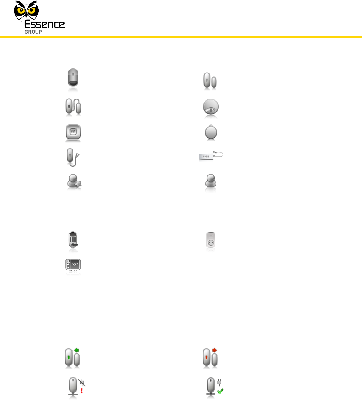
These icons may:
Change their color in accordance with their reported event/status (i.e. turn red
upon tampered event).
Presented with colored items:
Door/Window Magnetic
Sensor CLOSED
Door/Window Magnetic
Sensor OPENED
Power failure
Power restored
Installation of the We.R™ System
We.R™ System User Guide
55
Universal Transmitter CLOSED
Universal Transmitter OPENED
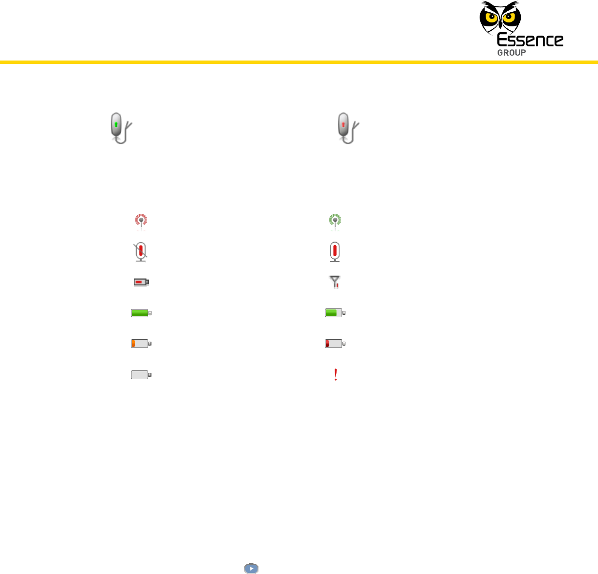
Presented with (or by) additional sub-icon symbolizing the status or event. These
additional event/status sub-icons could be:
APN failure
APN restored
Broken (Connection Lost)
Connection restored
Low battery
Low Connection
Battery FULL event
Battery NORMAL event
Battery LOW event
Battery CRITICAL event
Battery DEAD event
Warning (i.e. tamper, power
failure, etc.)
The Recent Events (right) pane – a detailed pane graphically (utilizing icons) presenting
a log of all system defined components which participated in the last events. Data
presented include time stamp (date and time) of the event and some additional text
explaining the nature of the event. The presentation icons are similar to the above
mentioned Devices Pane icons.
The Cameras (middle) pane (sub divided into upper and lower sub-panes) is used for
presentation of the images captured by the Camera devices of the system. The lower
part presents a graphical (utilizing icons) list of all system defined Cameras with their
system name. Clicking over one of them will present its captured images in the upper
sub-pane. Clicking over the button will run them in video-like mode.
In cases of special interfaces or applications (i.e. the Z-Wave® Controller), not only that the Tab
bar will be expanded to include two (2) additional Smart Home tabs, but the Dashboard page
Devices’ pane will display an icon presenting the interface/application. For example, in the case
of a Z-Wave® Controller, the following icon will present the Z-Wave® Controller:
Installation of the We.R™ System
56
We.R™ System User Guide
Figure 27: The Z-Wave® Controller Icon
And the Dashboard would look like:
Figure 28: The Dashboard Page with Z-Wave® Controller
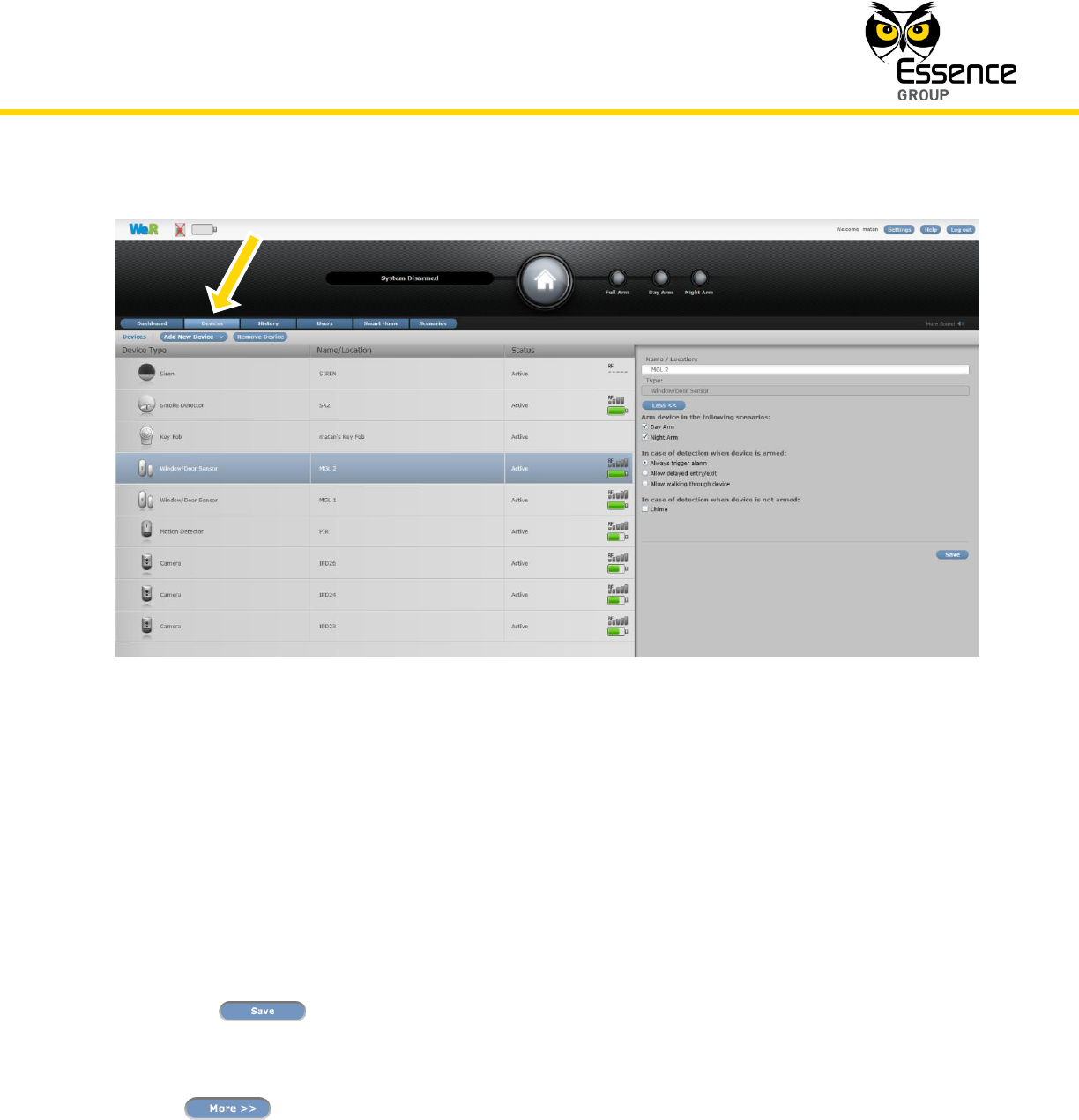
3.3.6.2. The Devices Page
The Devices page provides an overview of the We.R™ system defined devices and allows:
Addition or removal of Devices to the system (by Master User only).
Editing (by Master User only) of their operational characteristics.
Installation of the We.R™ System
We.R™ System User Guide
57
Figure 29: The Devices Page
This page divides into two (2) panes:
The Devices (left) pane – an overview pane presenting all system defined components,
their icon image (for type), their system given name/location and their current status
including icon indication of their signal strength and battery level.
Details of operational characteristics of the highlighted line-item (device) in the Devices
pane are displayed in the pane to the right – the details pane. These may be edited (by
a Master User only). Any change made to these details must be saved by clicking over
the button.
There is an extension of operational characteristics information for the sensor devices
(i.e. IPD, PIR, MGL etc.) which may be revealed and edited by clicking over the
button.
This button is available only when sensor devices are selected on the left Devices pane.
Installation of the We.R™ System
58
We.R™ System User Guide
Master User(s) may also add new device(s) to the system by clicking over the
button. A detailed explanation of such a procedure is provided within
every component installation paragraph in this guide.
Master User(s) may also remove device(s) from the system by selecting a device (line
item in the Devices pane) and clicking over the button. A detailed
explanation of such a procedure is provided within every component installation
paragraph in this guide.
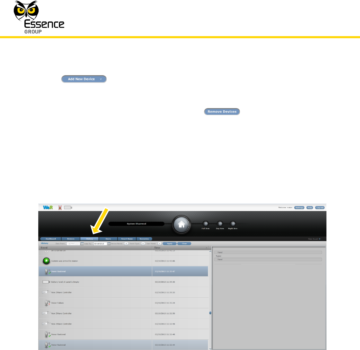
3.3.6.3. The History Page
The History page presents the system log of events.
Figure 30: The History Page
This page divides into two (2) panes in addition to a log-file filter definition tool bar:
Installation of the We.R™ System
We.R™ System User Guide
59
The Events (left) overview left pane displaying, in sequential order, all recorded system
events with:
Icon images of the items the event relates to,
Description of the event, and
A time-stamp (date and time) of the event.
Above the Events pane there is a History filter definition toolbar enabling definition of
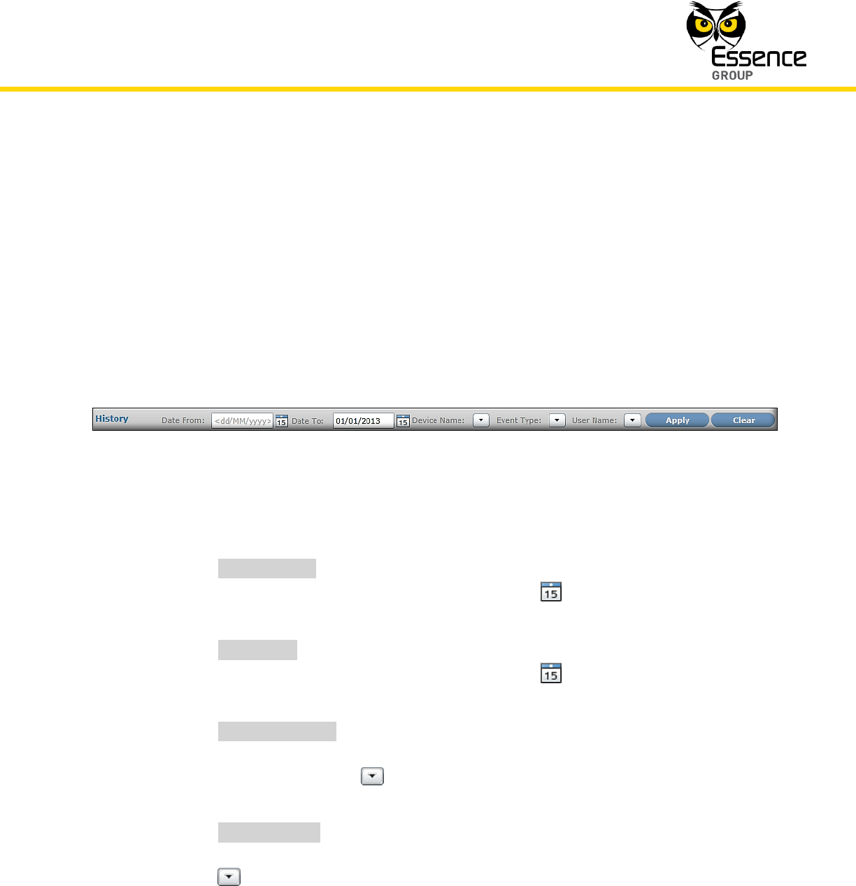
filtered data to be displayed in the Events pane.
Figure 31: The History Filter Toolbar
This toolbar include the following tools to define the filter:
1) _Date From:_ – defines the date from which the filter will allow pass data for
display. Date is selected by clicking over the button which opens
calendar-like menu for selection of the desired date.
2) _Date To:_ – defines the last date allowed for the filter to pass data for
display. Date is selected by clicking over the button which opens
calendar-like menu for selection of the desired date.
3) _Device Name:_ – allowing selection of which Devices will be presented by
the filter by Devices’ system (given) name. The specific Device(s) are selected
by clicking over the button which opens a selection roll-down menu
where the desired Device(s) need to be marked.
4) _Event Type:_ – allows selection of which event type(s) data will be passed
by the filter for display. The specific Event(s) are selected by clicking over the
button which opens a selection roll-down menu where the desired
Event(s) need to be marked.
Installation of the We.R™ System
60
We.R™ System User Guide
5) _User Name:_ – allows selection of which of the Users related devices will be
passed by the filter for display. The specific User(s) are selected by clicking
over the button which opens a selection roll-down menu where the
desired User(s) need to be marked.
Once these filter’s criteria are completely defined, applying them to see the filtered
results is done by clicking over the button.
To clear previous filter data – click over the button.
The characteristics of the highlighted line-item (Event) in the Event pane are presented
in the pane to the right.
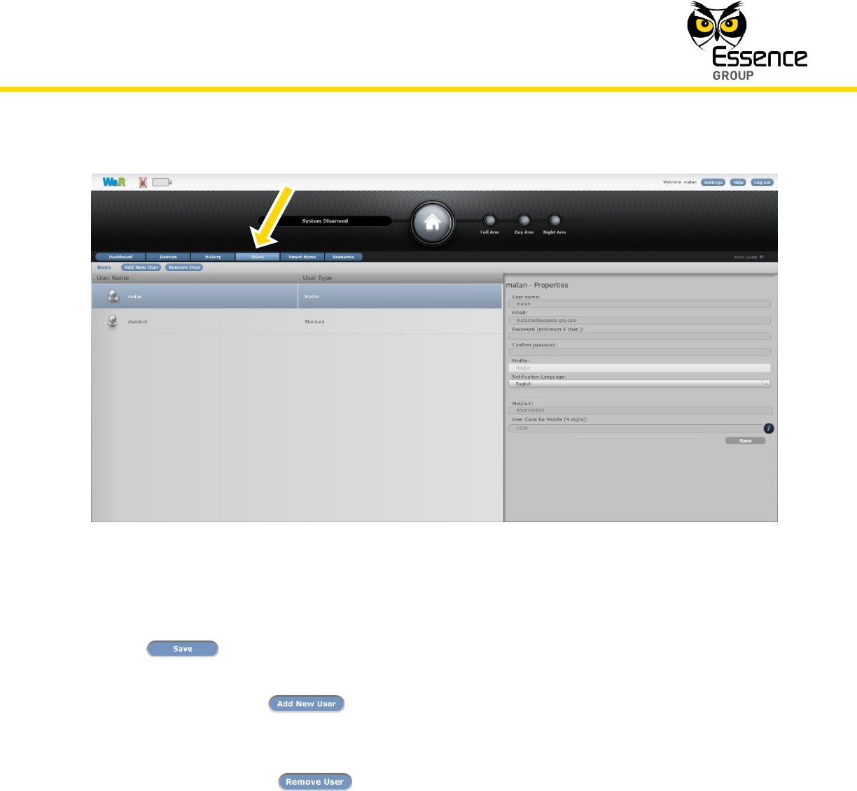
3.3.6.4. The Users Page
The Users page provides the system Users’ information.
The window divides into two (2) panes:
The left overview pane provides the User name and type.
The right details pane provides all required data of the highlighted User line-
item in the left pane. This data include:
The User name.
The User Email address (for notifications).
The User Profile – Standard or Master.
Notes: Unlike a Standard User, a Master User may modify the system
configuration data, system Users data etc.
Up to two (2) Master Users may be defined in a single system.
Maximum total of 32 Users are supported by a single system.
The Notification Language.
The User Code (four digits) for the Mobile Application.
The ability to edit the User’s password.
Installation of the We.R™ System
We.R™ System User Guide
61
Figure 32: The Users Page
Once any of the above data fields have been changed; there is a need to click over the
button to store the new data into the system configuration files.
New Users may be added (up to the system limits, see Table 5 on page 194) by
clicking over the button. This will initiate a new line item on the left pane and
empty data fields on the right one to be typed-in.
Users may also be removed from the system by clicking over the specific User line item
and then over the button.
3.3.6.5. The Smart Home and Scenarios Pages
The Smart Home page and its associated Scenarios page, deals with Smart Home controllers
like the We.R™ Z-Wave® Controller and will be explained in paragraph 3.14.4. Activating the Z-
Wave® Controller below.
Installation of the We.R™ System
62
We.R™ System User Guide
3.3.6.6. Other Pages
As the We.R™ system gains more and more applications and interfaces, special purpose
pages are (and will be) added to the Data Window to provide User Interfaces for such special
purposes.
The explanations for these additional pages, within this User Guide, are provided in the
paragraphs discussing such applications and interfaces (i.e. the Scenarios page in the We.R™
Z-Wave® Controller).
3.4. The We.R™ Mobile Application
Note: The We.R™ Mobile Application is based on the We.R™ Web
Application and built to allow mobile (smartphones and tablet computers)
administration of the We.R™ system.
Its details below are added at this point in time, since this knowledge could
serve as a helpful tool for the installation process of the system devices by
allowing mobility of the installer around the premises.
The We.R™ Mobile Application is designed for reliability and low latency, top-tier home
management solution for controlling and managing the We.R™ system via mobile devices.
It contains a communication engine ensuring everlasting connectivity to the server and a push-
notification message mechanism in case of alarms and events. The application is designed to
consume minimal amount of power for battery preservation for longer time of operation.
The We.R™ Mobile Application is available for iPhone® iOS operating system (OS) for
smartphones and tablets as well as for Google™ Android™ OS for smartphones and tablets.
Note: Differences between the Android™ and the iOS operating systems
and smartphones might result with some minor dissimilarity between the
screens captures presented below.
Installation of the We.R™ System
We.R™ System User Guide
63
It features the following home management functions:
Push notifications for triggered events
System status
Arm activation (Full Arm, Day Arm, Night Arm)
Look-in via live imaging
Events history and filtering of events history
View GSM signal strength (for CCU model with a SIM-card)
Multilingual support
Device statuses
Smart Home control via Z-Wave® devices (i.e. thermostat, dimmer, doorlock)
3.4.1. Downloading and Installing the We.R™ Mobile Application
The Mobile Application, for both Apple® iPhone® (iOS)
and Android™ users, may be downloaded later from
the following QR-code link:
(or search within Apple’s App Store or Google’s Play
for We.R™)
These applications guide the user through all phases
of the identification, installation and registration
process.
Once the software is downloaded and the installation process has ended, the following Login
screen will pop-up:
Installation of the We.R™ System
64
We.R™ System User Guide
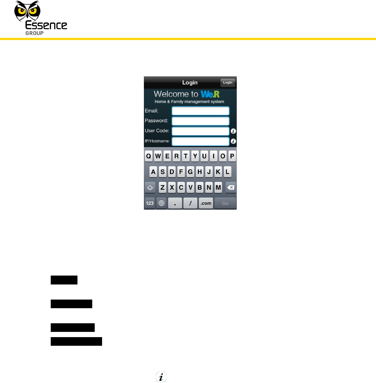
Figure 33: The Login Screen
Similar to the First Time Registration procedure (see above page 40), in this screen you need to
type-in the following information:
1. _Email:_ – Your email address for push messages and notifications. This need to be the
same address provided within the above-mentioned First Time Registration procedure.
2. _Password:_ – Your password. This need to be the same password provided within the
above-mentioned First Time Registration procedure.
3. _User Code:_ –User Code initiated within the above First Time Registration procedure.
4. _IP/Hostname:_ – The Service Provider’s URL. This IP address (or Hostname) is provided
to you by the We.R™ dealer where you purchased the We.R™ system, usually on a sticker
attached to the box.
The last two items has an additional icon which, by clicking over it, provides help text to
explain the content of the field.
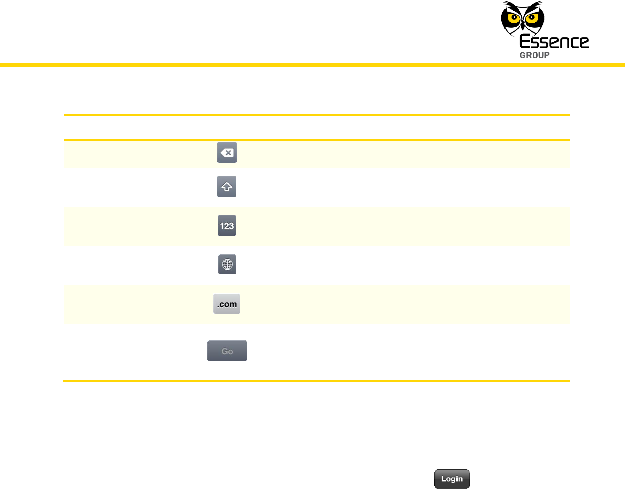
The virtual keyboard on this screen has some special keys:
Installation of the We.R™ System
We.R™ System User Guide
65
Key Name
Icon
Description
Backspace
Used to erase characters.
Uppercase
Used for globally switching the keyboard between upper
and lower case characters.
Numeric
Used for globally switching the keyboard between
alphabetic keys and numeric keys.
Language
Used for globally switching the keyboard character-set
between languages.
COM Shortcut
This is a shortcut key inserting the .COM extension for
Email and IP/Hostname fields.
Go
Once all data is properly typed-in, this key terminates the
Login data entry process and sends the data to the
servers.
Table 3: Special Keys on the Login Virtual Keyboard
In addition to the above-mentioned keys, there is another special key, on the top-right end of
the screen, allowing immediate login following entry of all data fields – .
3.4.2. Limitations of the We.R™ Mobile Application
As mentioned before, the We.R™ Mobile Application is an extension of the Web Application.
But, being a mobile application running over the limited resources of mobile devices and their
operating systems, some of the Web Application’s features had to be omitted. These are:
The Mobile Application does not allow settings (adding/modifying) of system Users.
The Mobile Application does not allow settings (adding/modifying) of system Devices.
In addition, if the We.R™ Mobile Application is installed on multiple mobile devices for a specific
User, the push notifications might not be received by all of them.
Installation of the We.R™ System
66
We.R™ System User Guide
3.4.3. Using the Mobile Application
The installation of the We.R™ Mobile Application creates, among other things, an icon on the
mobile device’s main screen. Tapping over this icon will activate the We.R™ Mobile Application.
Figure 34: The Mobile Application Icon
If never registered before, the first screen to pop-up is presented in Figure 33 above. The
registration need to be completed (see paragraph 3.4.1 above) prior to the usage of the Mobile
Application.
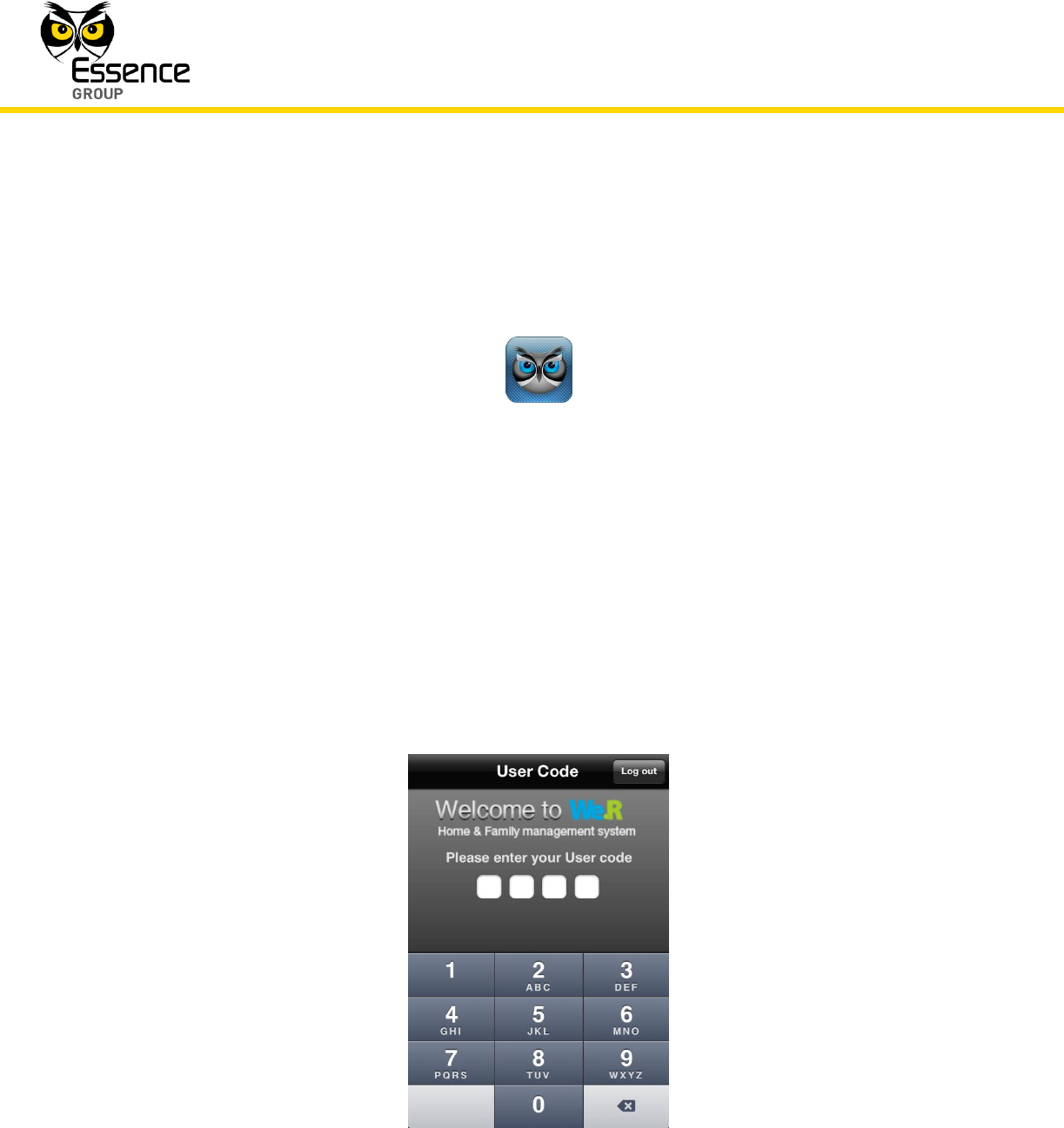
3.4.3.1. The User Code Screen
In case the Mobile Application was properly installed and registered, the first screen to pop-up
is:
Figure 35: The User Code Login Screen
Installation of the We.R™ System
We.R™ System User Guide
67
Type-in the 4-digits User Code set during the registration procedure described in the above
paragraph 3.4.1.
The virtual keyboard’s backspace button may be used for deletion of erroneous input
while the button allows termination of the Login process.
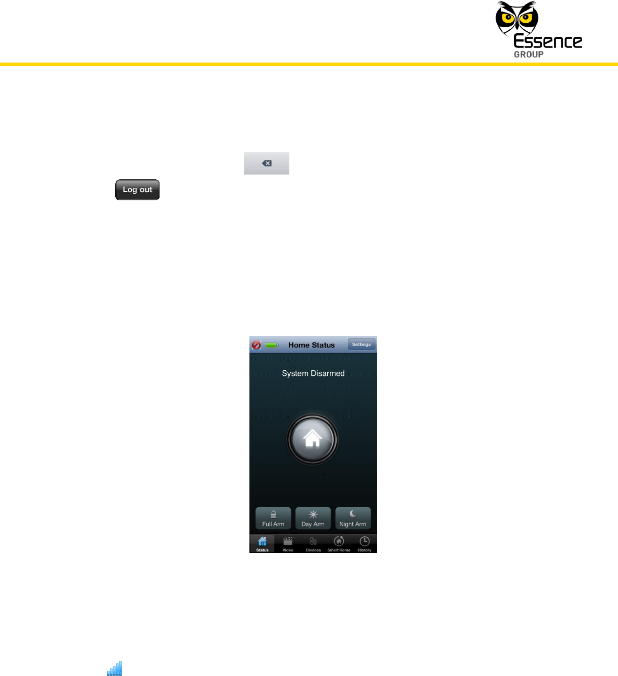
3.4.3.2. The Home Status (Main) Screen
Once the correct User Code is typed-in, the Mobile Application logs onto the Service
Provider’s servers and becomes fully functional.
The opening screen to pop-up next is the Home Status (Main) screen:
Figure 36: The Home Status Screen
The Home Status is similar, in appearance and functionality, to the Web Application’s We.R™
Dashboard Page (see above sub-paragraph 3.3.6.1):
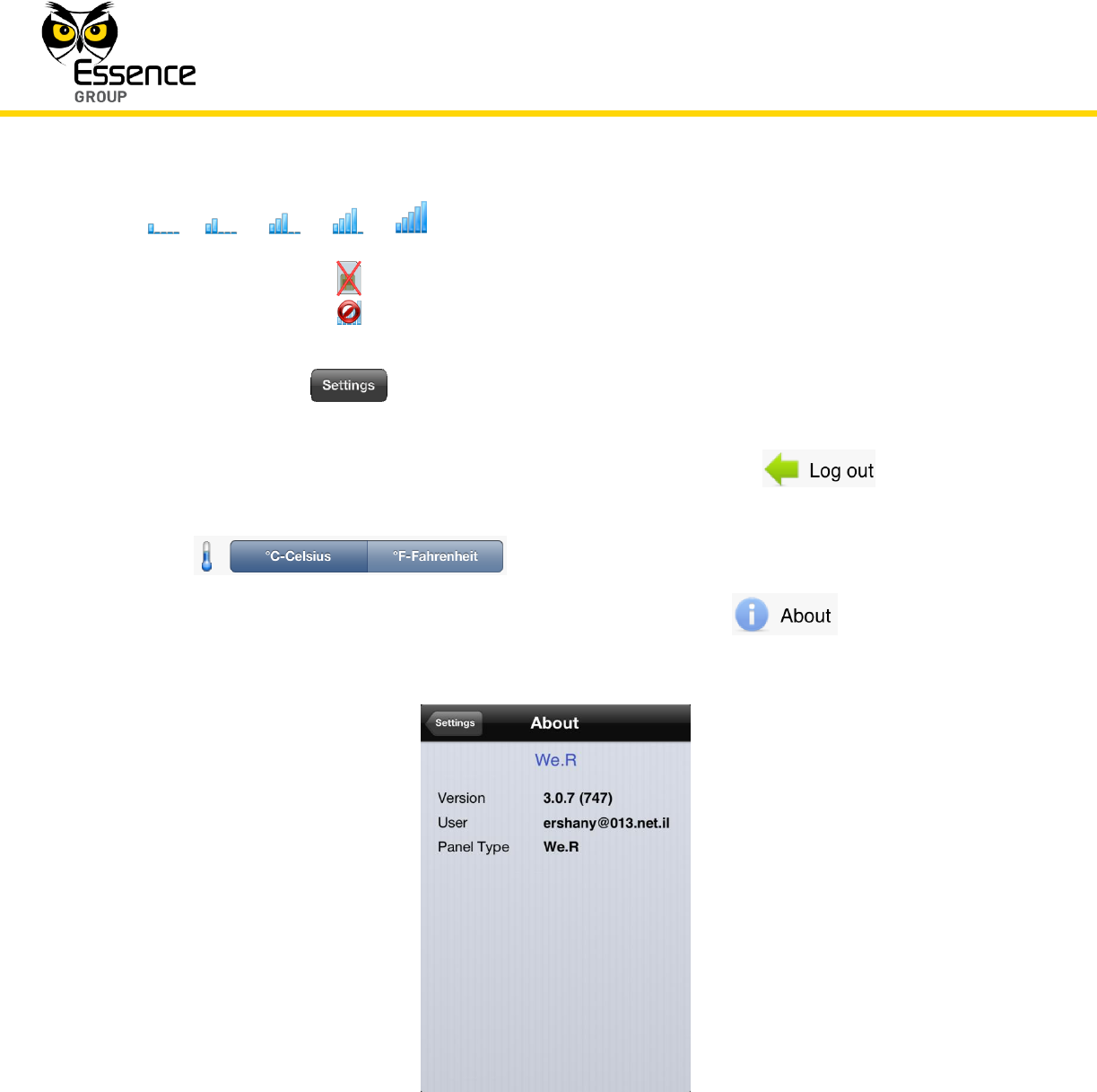
1. The icon on the top-left side of the screen is a RF signal strength meter of the CCU’s
cellular signal. It could display:
Installation of the We.R™ System
68
We.R™ System User Guide
or or or or
Signal strength meter indicating the CCU’s cellular
signal strength.
No SIM-card installed in the CCU.
Cellular channel communication lost.
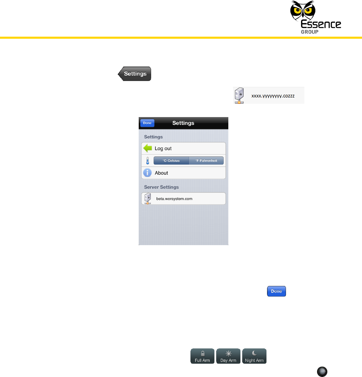
2. Tapping over the button at the top-right side of the screen, will switch the mobile
device into the Settings screen (see Figure 38 below) where you may:
i. Log out of the We.R™ Mobile Application by tapping over the .
ii. Select temperate display units between Celsius and Fahrenheit with the
.
iii. Bring up the system information page by tapping over the . This will open
the following screen:
Figure 37: The About Screen
This page provides the We.R™ Mobile Application software version, the registered
User email address and the CCU (Panel) type.
Installation of the We.R™ System
We.R™ System User Guide
69
Tapping over the button will switch the screen back to the Settings screen.
iv. View the Service Provider’s servers address (URL) with
Figure 38: The Settings Screen
Upon completion of settings, terminate the session by tapping over the button.
3. The center piece is similar, in appearance and functionality, to the Web Application’s
Status/Activation Bar (see above paragraph 3.3.5) providing, at a glance, real-time
information about the system status as well as enabling basic system arming commands;
Tapping over any of the three arming buttons ( , , ) will trigger the
system into the operation mode called for (Full Arm, Day Arm or Night Arm), just like the
arming buttons in the Status/Activation Bar.
Installation of the We.R™ System
70
We.R™ System User Guide
Note: Definition of arming modes is set via the We.R™ Web Application
only, utilizing the Devices Page. See paragraph 4.5. Managing Devices
below
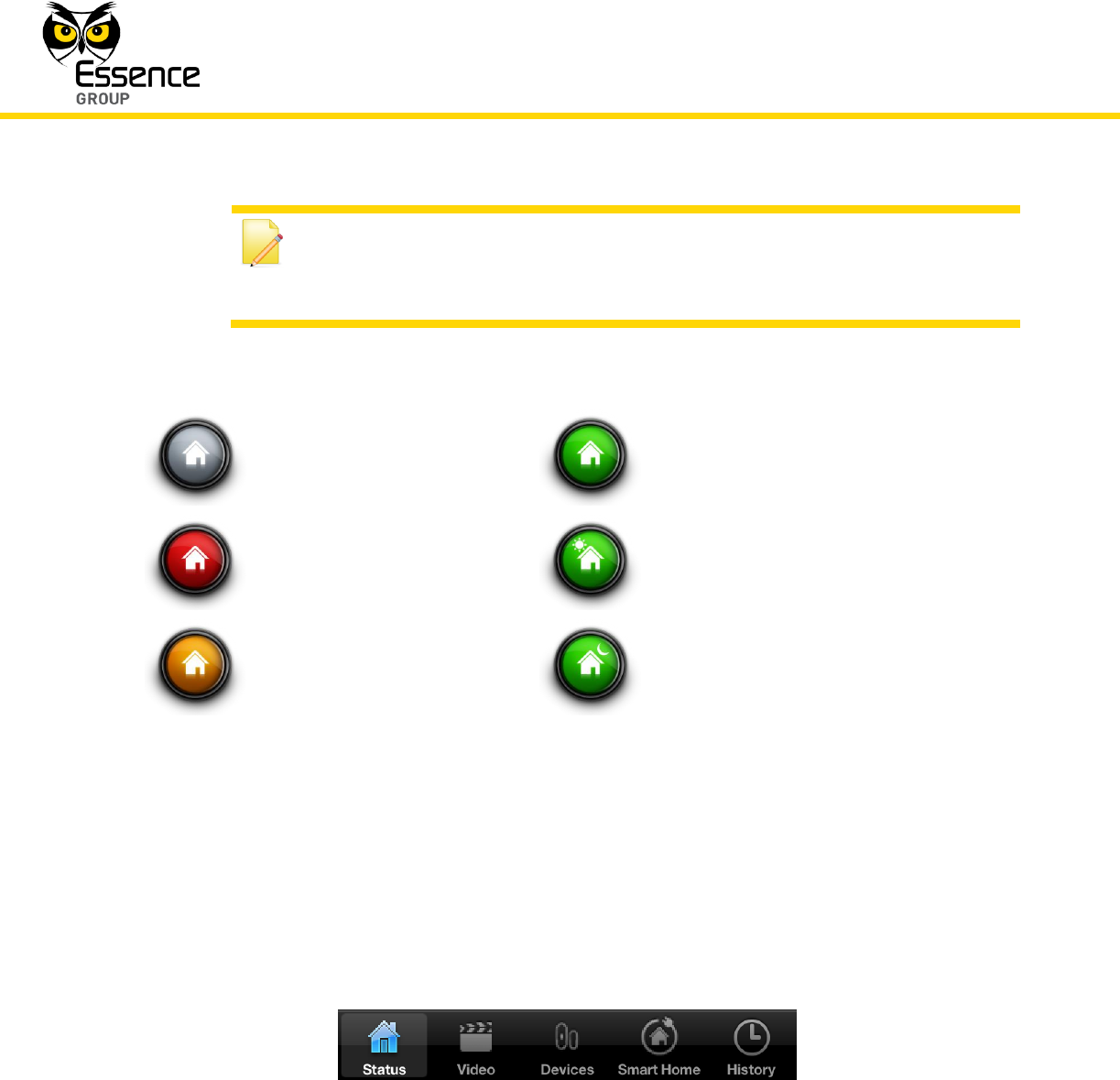
The system status is reflected by the image and color of the central icon as follows:
(grey)
System Disarmed
(green)
System (fully) Armed
(red)
Burglary Alarm
(green)
System Day Armed
(yellow)
Safety Hazard
(green)
System Night Armed
The text messages, on top of this icon, word-out the meaning of the image on display.
4. The Tab Bar at the bottom of the screen provides similar functionality to the Tab Bar of the
We.R™ Web Application allowing quick access to the different display functions (screens) of
the We.R™ Mobile Application.
Figure 39: The Home Status Screen Tab Bar
The Status Tab/screen returns the mobile device’s display to the Home Status (Main)
screen (see above Figure 36).
Installation of the We.R™ System
We.R™ System User Guide
71
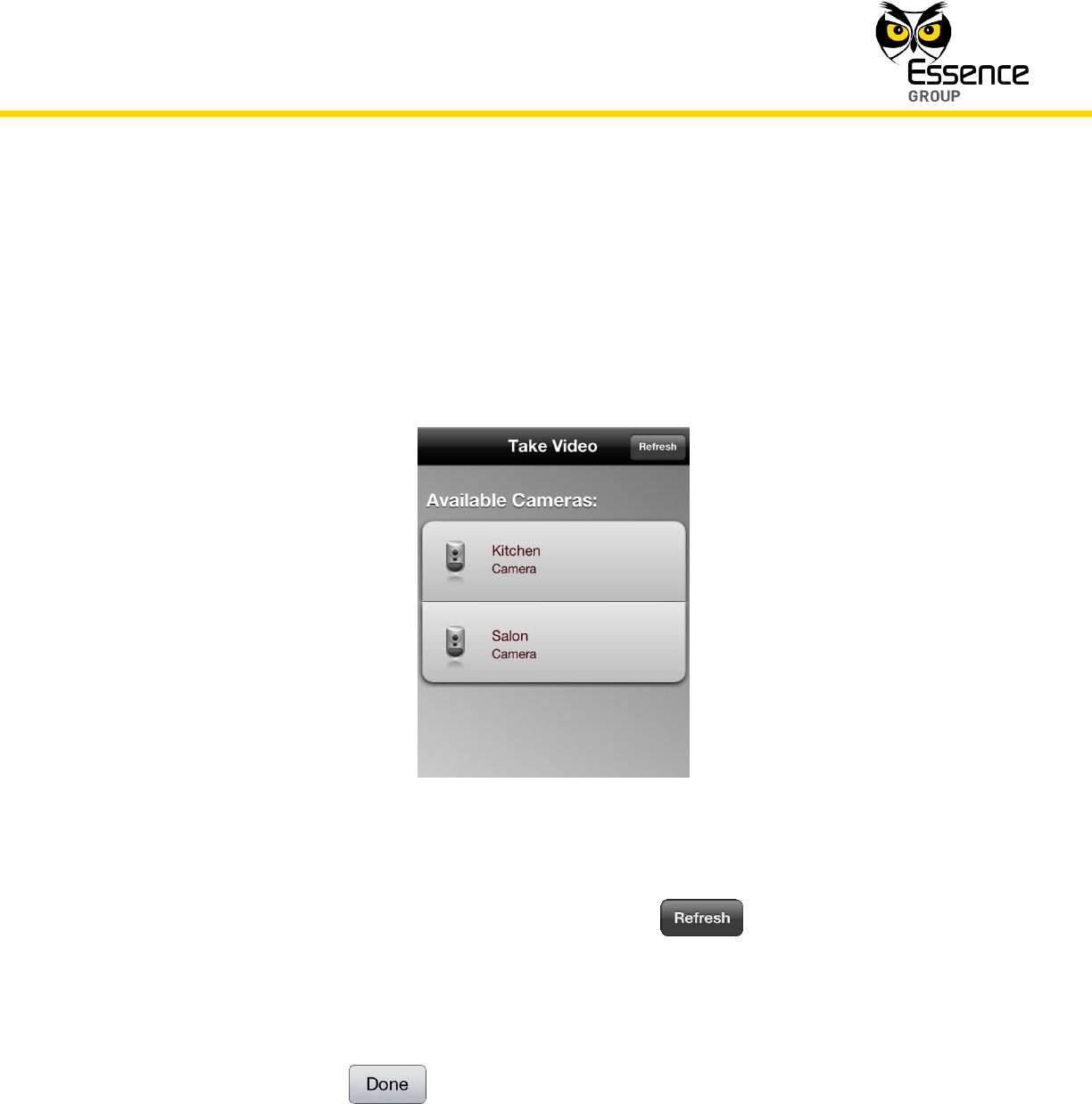
The Video Tab/screen allows comfort (non-alarm triggered, initiated by the User) view
of the environment where the camera is installed.
Tapping over the Video Tab will switch the display to the Take Video screen (see Figure
40 below). This screen displays all cameras included in your system and the desired
camera should be selected out of this list.
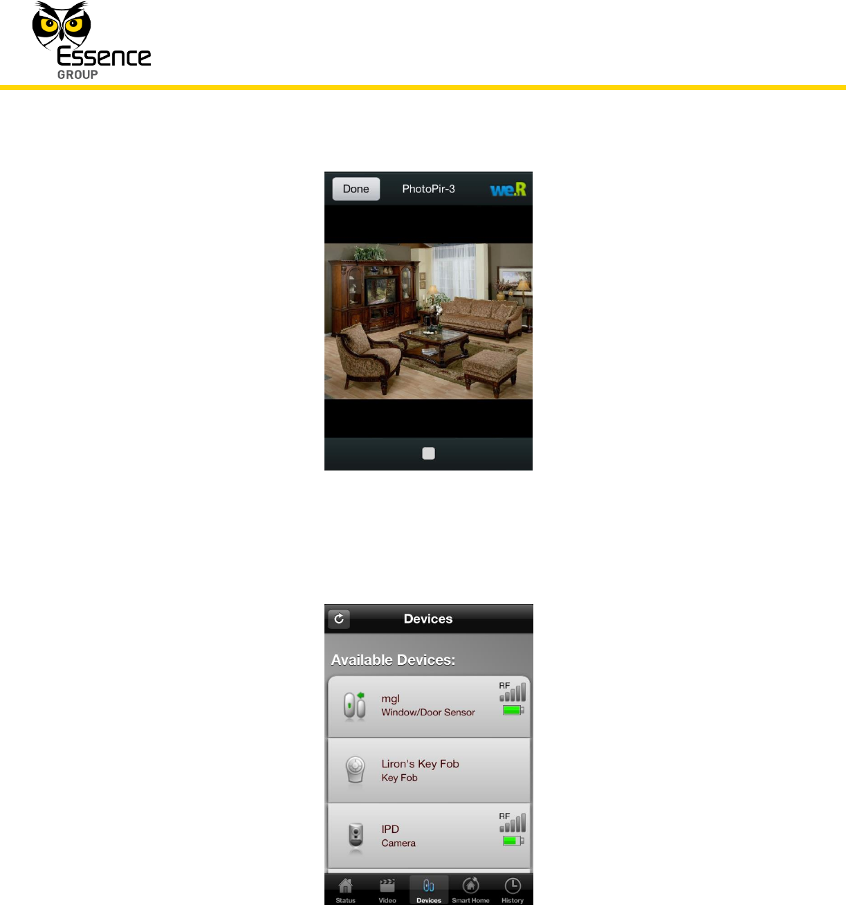
Figure 40: The Take Video Screen
To refresh the Available Cameras list – tap over the button.
Tapping over one of the cameras in the list will select it and will switch the screen into a
camera display screen presenting the view in front of the camera.
The square button at the bottom of this screen is your Play/Pause switch.
Tapping over the button will terminate the comfort video session and return
the display to the Home Status (Main) screen (see above Figure 36).
Installation of the We.R™ System
72
We.R™ System User Guide
Figure 41: Comfort View of Camera
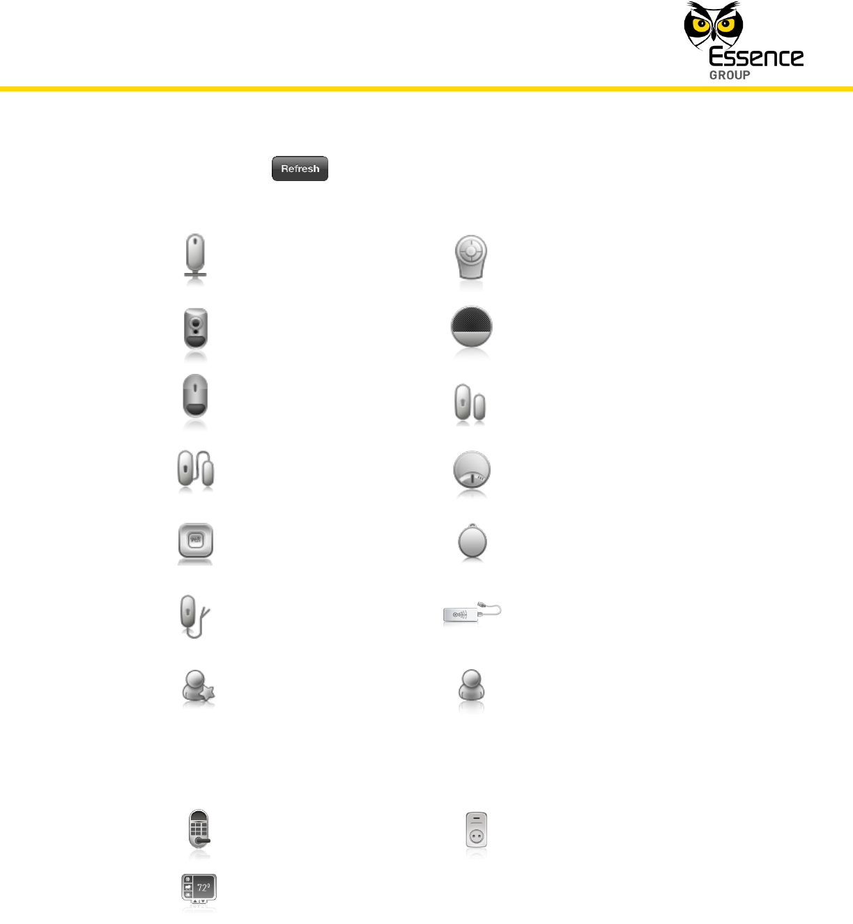
The Devices Tab/screen opens a status screen presenting all system devices and their
events/status icons similar to the Devices Page of the We.R™ Web Application:
Figure 42: Devices Screen
Installation of the We.R™ System
We.R™ System User Guide
73
Tapping over the button refreshes the content of this status screen.
The devices’ icons are similar to the icons used in the We.R™ Web Application:
Central Control Unit
Remote Control Unit (KF)
Motion Indoor Photo
Detector
Indoor Siren
Motion Detector
Door/Window Magnetic
Sensor
Flood Detector
Smoke Detector
Wireless Access Control
Tag Reader
Tag
Universal Transmitter
Z-Wave® Controller
Master User
Normal User
Three (3) more devices’ icons are used for the Z-Wave® devices presented on the
Smart Home and Scenarios pages:
Z-Wave® device type
Doorlock
Z-Wave® device type
Switch or Dimmer
Z-Wave® device type
Thermostat
Installation of the We.R™ System
74
We.R™ System User Guide
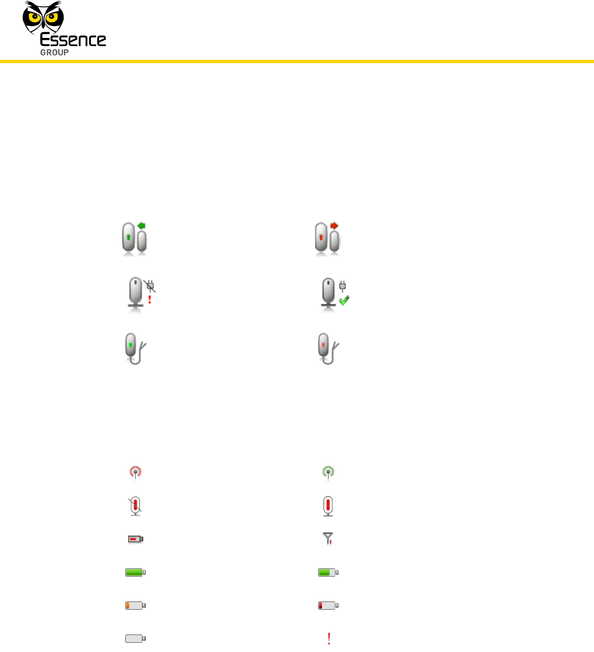
These icons may:
Change their color in accordance with their reported event/status (i.e. turn
red upon tampered event).
Presented with colored items:
Door/Window Magnetic
Sensor CLOSED
Door/Window Magnetic
Sensor OPENED
Power failure
Power restored
Universal Transmitter
CLOSED
Universal Transmitter
OPENED
Presented with (or by) additional sub-icon symbolizing the status or event.
These additional event/status sub-icons could be:
APN failure
APN restored
Broken (Connection Lost)
Connection restored
Low battery
Low Connection
Battery FULL event
Battery NORMAL event
Battery LOW event
Battery CRITICAL event
Battery DEAD event
Warning
Installation of the We.R™ System
We.R™ System User Guide
75
Note: As mentioned before, the We.R™ Mobile Application allows devices’
status display only and cannot be used for their setup.
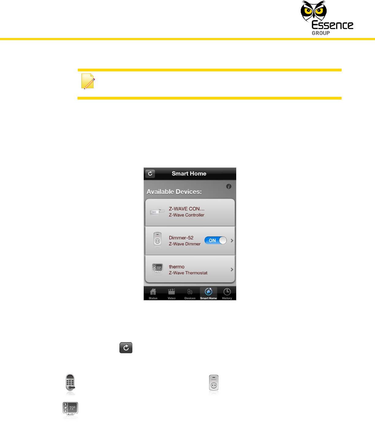
The Smart Home Tab/screen opens a status screen for all system Z-Wave® devices
with their events/status icons similar to the Smart Home Page of the We.R™ Web
Application:
Figure 43: Smart Home Screen
Tapping over the button refreshes the content of this screen.
The devices’ icons are similar to the icons used in the We.R™ Web Application:
Z-Wave® device type
Doorlock
Z-Wave® device type
Switch or Dimmer
Z-Wave® device type
Thermostat
Installation of the We.R™ System
76
We.R™ System User Guide
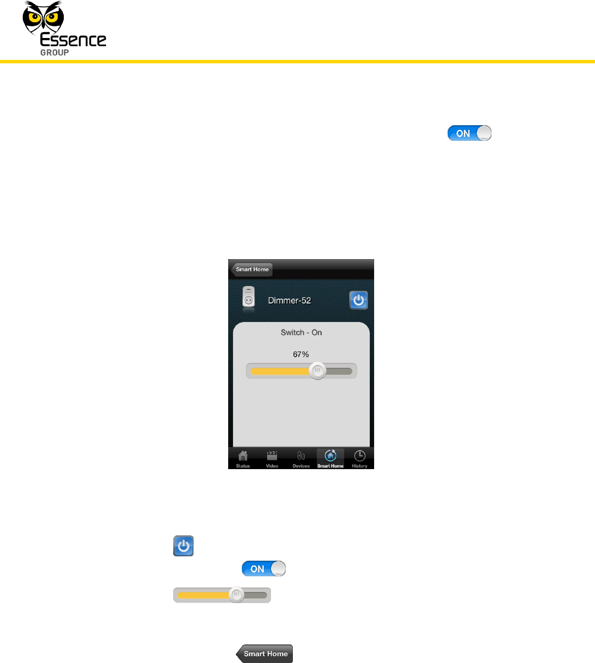
For switch-mode devices (Z-Wave® Switch and Dimmer class), switching the device
ON and OFF is possible directly from this screen by tapping over the button.
For devices which may present more details, an is added to the right. Tapping over
this will switch the display into a new screen expanding on the information related to
the specific device. For example:
Expansion screen for Dimmer class devices:
Figure 44: Dimmer Class Device Expansion Screen
The button provides device ON/OFF switching function (similar to the
above mentioned button).
The slide control provides analog control of the dimmer
level.
Once all features are set, going back to the Smart Home screen is done by
tapping over the button.
Installation of the We.R™ System
We.R™ System User Guide
77
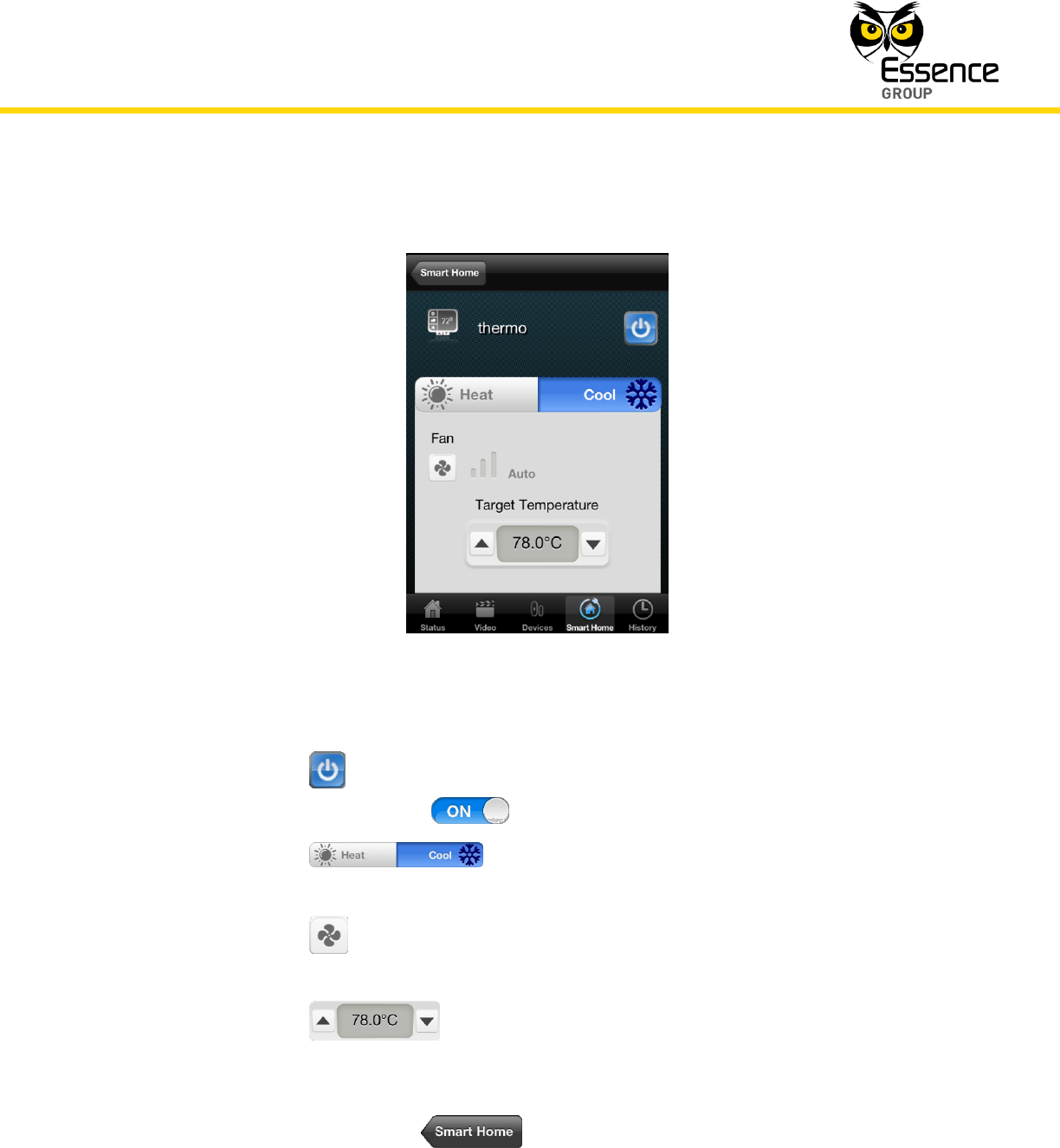
Expansion screen for Thermostat class devices:
Figure 45: Thermostat Class Device Expansion Screen
The button provides device ON/OFF switching function (similar to the
above mentioned button).
The switch provides selection between cooling and
heating.
The is a multi-level fan speed selector where each tap progress the
speed in one step.
The is an up/down temperature setting selector where the
temperature display is set by the Settings screen (see Figure 38 above).
Once all features are set, going back to the Smart Home screen is done by
tapping over the button.
Installation of the We.R™ System
78
We.R™ System User Guide
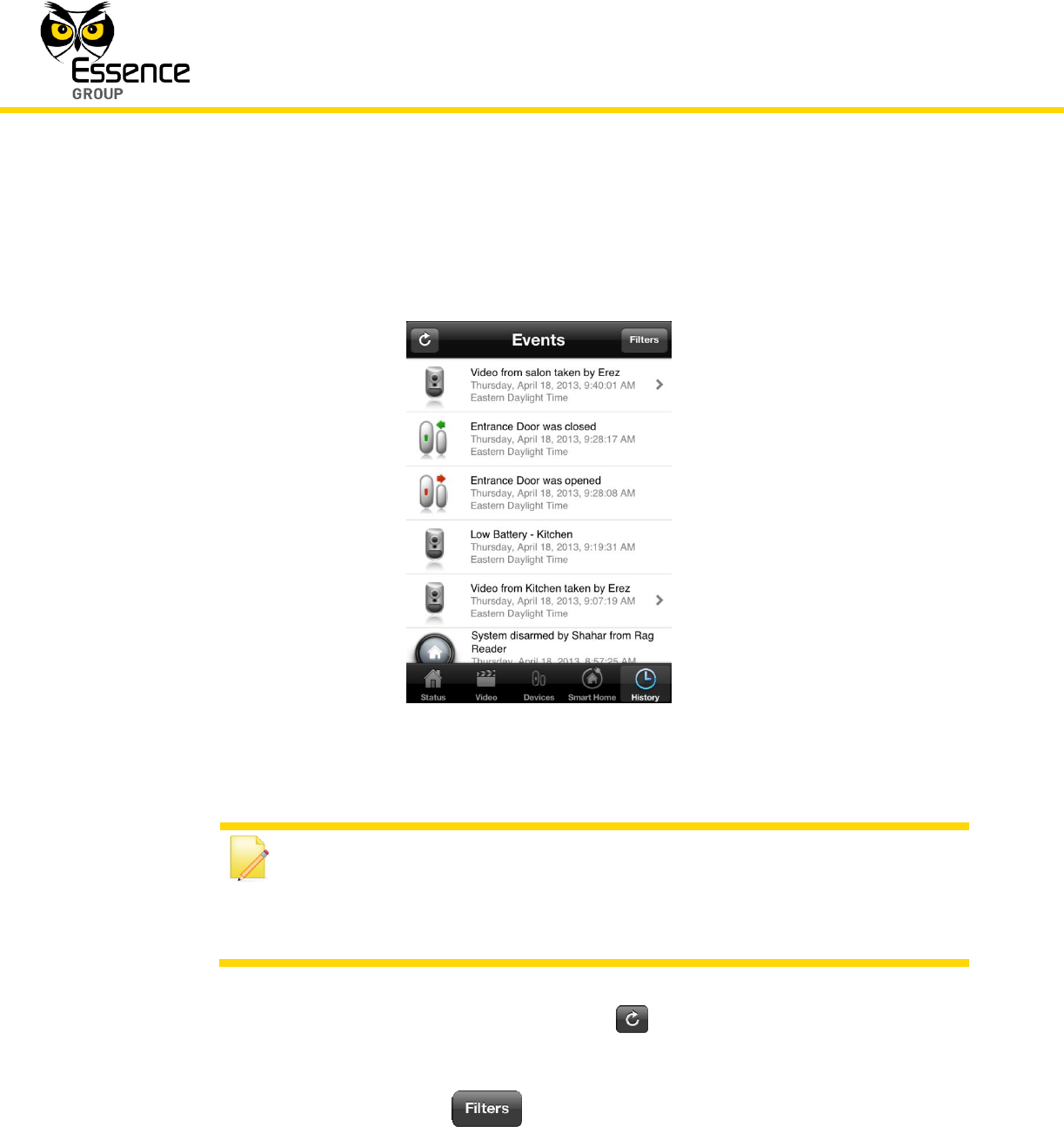
The History Tab/screen opens a screen presenting the complete log of the system
events:
Figure 46: History of Events Log Screen
Note: Devices which may present history with more details are marked with
icon on the right. Tapping over the icon will switch the display into a
new screen expanding the history information related to the specific device
and event.
You may refresh this screen by tapping over the button.
You may also limit the amount of data displayed by filtering it.
To filter the data, tap over the button. A filter tool bar will pop up above the log
(see Figure 47 below).
Installation of the We.R™ System
We.R™ System User Guide
79
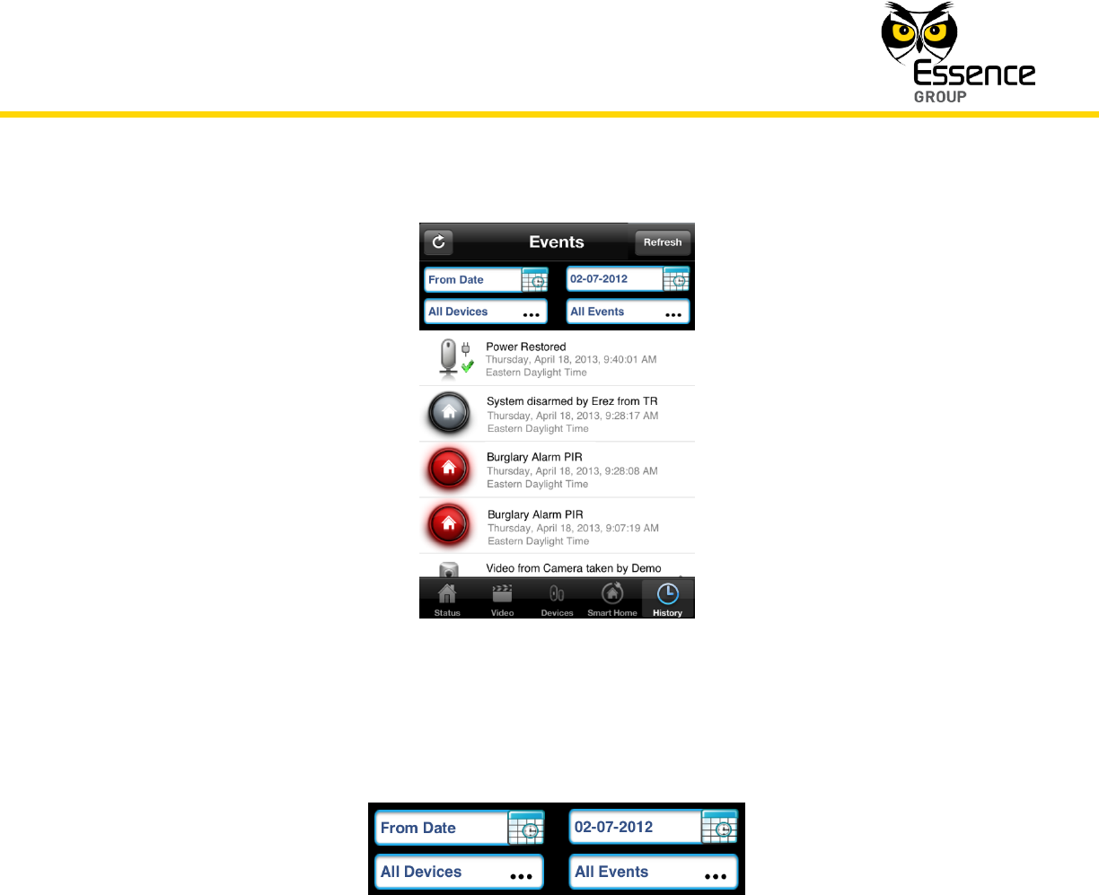
Figure 47: Events History Screen with Filter Tool Bar
The tool bar provides four (4) filtering criteria:
Figure 48: Filter Criteria
From Date – defines the first date to be included on display.
Tapping over this button will open a calendar-style menu, out of which the
first date to be included in the report should be selected.
To Date – defines the last date to be included on display.
Tapping over this button will open a calendar-style menu, out of which the
last date to be included in the report should be selected.
Installation of the We.R™ System
80
We.R™ System User Guide
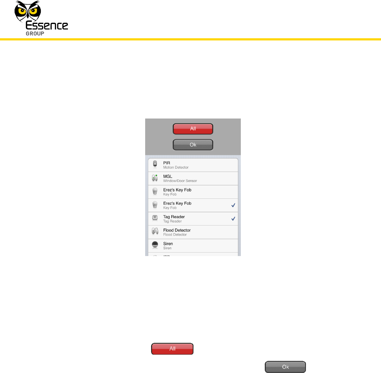
All Devices – defines which devices’ events will be included on display.
Tapping over this button will open the following screen:
Figure 49: Devices’ Criteria Selection Screen
Presented in this screen are all system defined devices, out of which you may
select those that you want to be included in the Events History report screen
(i.e. Sirens only, PIRs + Sirens, etc.).
Selection may be done either by tapping over each device you need or by
tapping over the button to select all devices.
Once selection was made, you need to tap over the button to
go back to the Events History screen (see Figure 47 above).
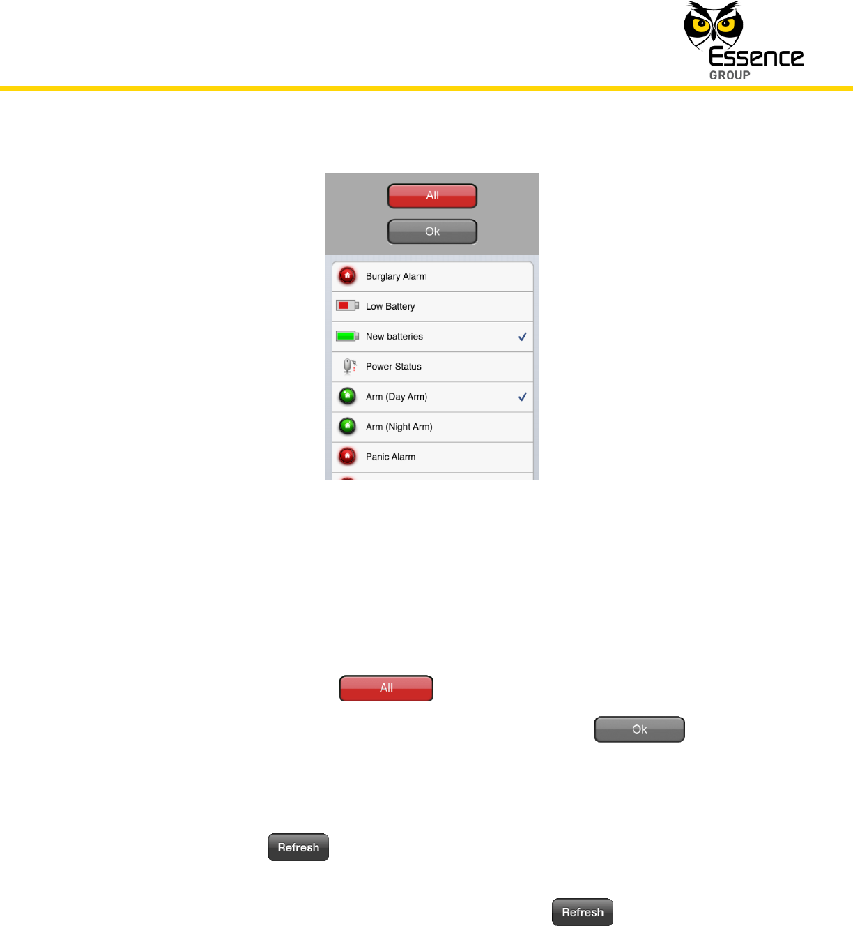
All Events – defines which types of events will be included on display.
Tapping over this button will open the following screen:
Installation of the We.R™ System
We.R™ System User Guide
81
Figure 50: Events’ Criteria Selection Screen
Presented in this screen is a log of all system events, out of which you may
select those that you want to be included in the Events History report screen
(i.e. Panic Alarms, Low Batteries + New Batteries events, etc.).
Selection may be done either by tapping over each event you need or by
tapping over the button to select all events.
Once selection was made, you need to tap over the button to
go back to the Events History screen (see Figure 47 above).
Once all filter criteria are set, the Events History report screen need to be refreshed, by
tapping over the button, to see the filtered report.
Logical conjunction results (filtered results) of ALL the above criteria will be displayed on
this screen as soon as these criteria are defined and the button is tapped
upon.