Everspring Industry Co SM103 Wireless Alarm System 908.42MHz User Manual
Everspring Industry Co Ltd Wireless Alarm System 908.42MHz
UserManual.wiki
>
Everspring Industry Co
>
SM103 User Manual
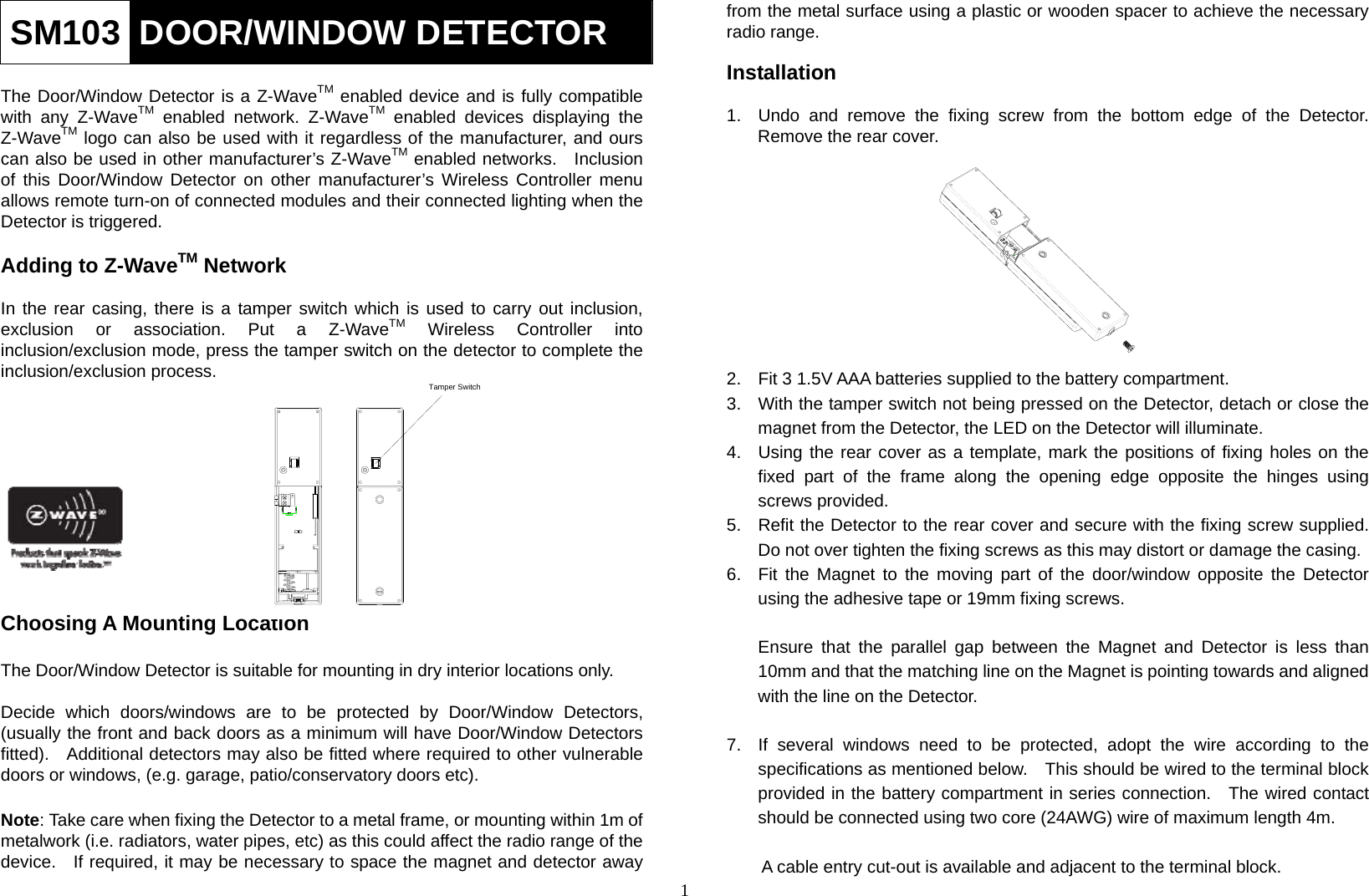
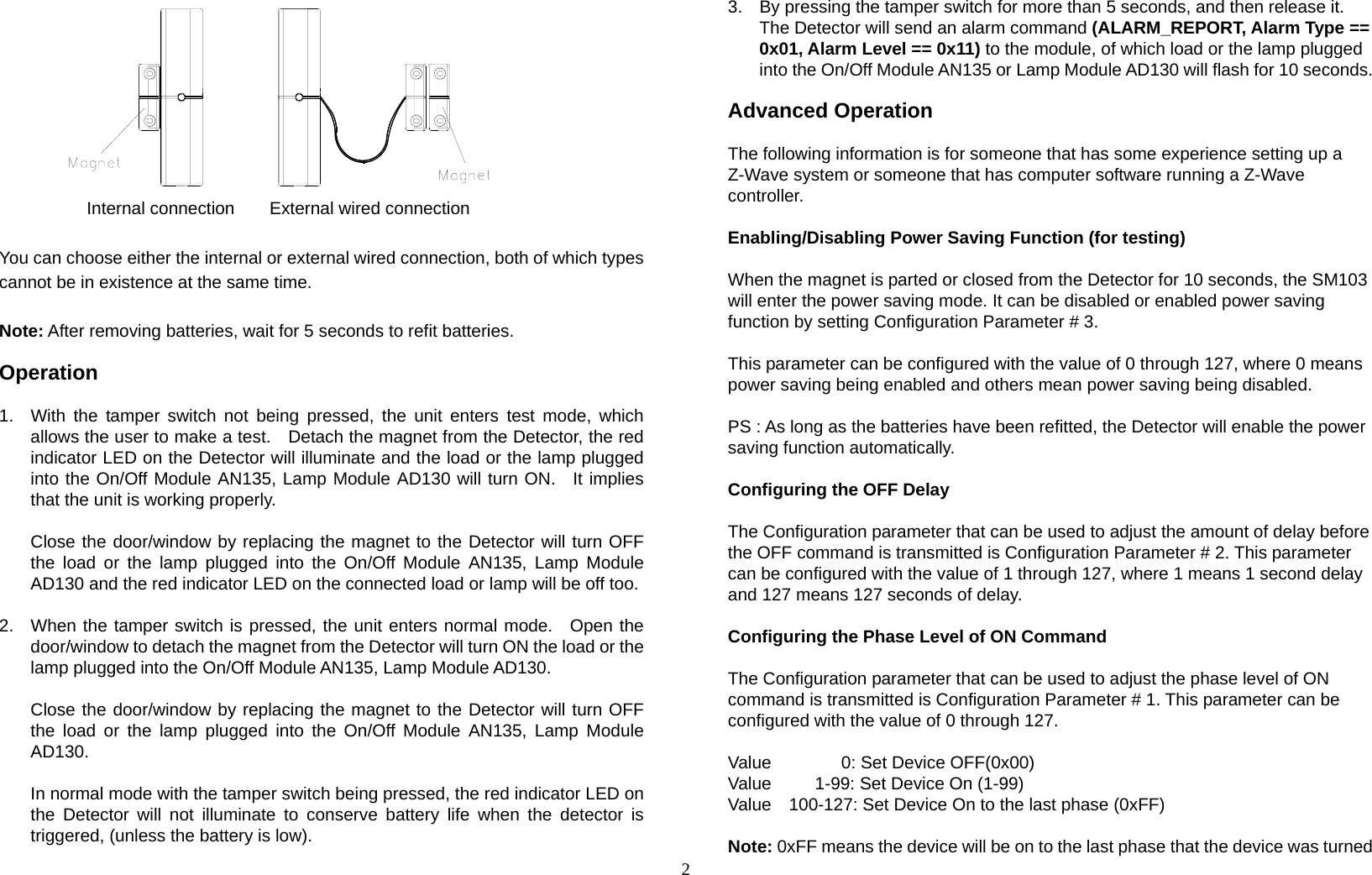
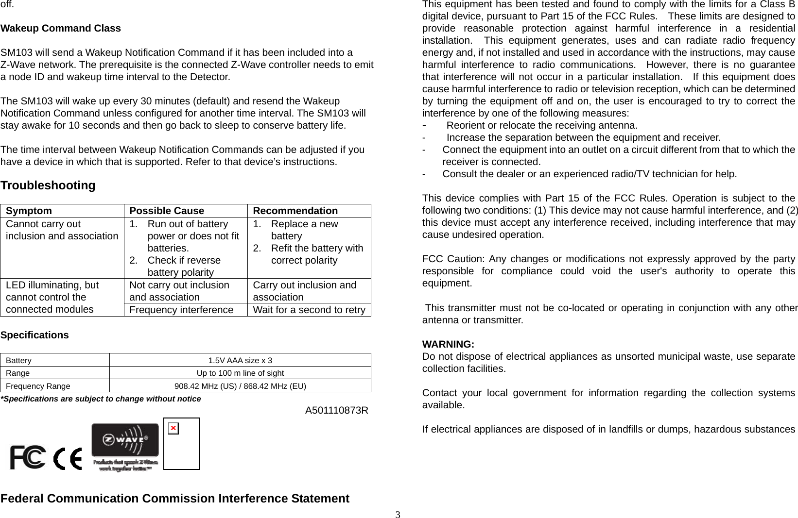
Users manual
Navigation menu
Upload a User Manual
Namespaces
Wiki Guide
HTML
PDF
Info
Views
User Manual
Discussion / Help
Navigation