Everspring Industry Co SM103 Wireless Alarm System 908.42MHz User Manual
Everspring Industry Co Ltd Wireless Alarm System 908.42MHz
Users manual
1
SM103 DOOR/WINDOW DETECTOR
The Door/Window Detector is a Z-WaveTM enabled device and is fully compatible
with any Z-WaveTM enabled network. Z-WaveTM enabled devices displaying the
Z-WaveTM logo can also be used with it regardless of the manufacturer, and ours
can also be used in other manufacturer’s Z-WaveTM enabled networks. Inclusion
of this Door/Window Detector on other manufacturer’s Wireless Controller menu
allows remote turn-on of connected modules and their connected lighting when the
Detector is triggered.
Adding to Z-WaveTM Network
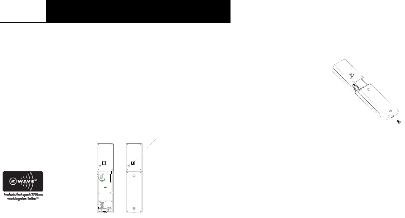
In the rear casing, there is a tamper switch which is used to carry out inclusion,
exclusion or association. Put a Z-WaveTM Wireless Controller into
inclusion/exclusion mode, press the tamper switch on the detector to complete the
inclusion/exclusion process.
Choosing A Mounting Location
The Door/Window Detector is suitable for mounting in dry interior locations only.
Decide which doors/windows are to be protected by Door/Window Detectors,
(usually the front and back doors as a minimum will have Door/Window Detectors
fitted). Additional detectors may also be fitted where required to other vulnerable
doors or windows, (e.g. garage, patio/conservatory doors etc).
Note: Take care when fixing the Detector to a metal frame, or mounting within 1m of
metalwork (i.e. radiators, water pipes, etc) as this could affect the radio range of the
device. If required, it may be necessary to space the magnet and detector away
from the metal surface using a plastic or wooden spacer to achieve the necessary
radio range.
Installation
1. Undo and remove the fixing screw from the bottom edge of the Detector.
Remove the rear cover.
2. Fit 3 1.5V AAA batteries supplied to the battery compartment.
3. With the tamper switch not being pressed on the Detector, detach or close the
magnet from the Detector, the LED on the Detector will illuminate.
4. Using the rear cover as a template, mark the positions of fixing holes on the
fixed part of the frame along the opening edge opposite the hinges using
screws provided.
5. Refit the Detector to the rear cover and secure with the fixing screw supplied.
Do not over tighten the fixing screws as this may distort or damage the casing.
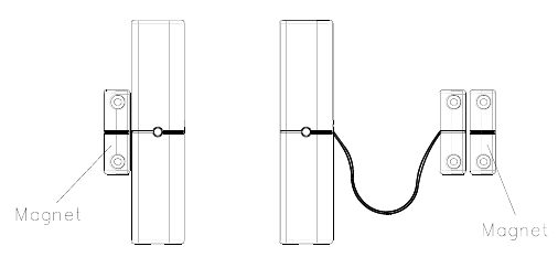
6. Fit the Magnet to the moving part of the door/window opposite the Detector
using the adhesive tape or 19mm fixing screws.
Ensure that the parallel gap between the Magnet and Detector is less than
10mm and that the matching line on the Magnet is pointing towards and aligned
with the line on the Detector.
7. If several windows need to be protected, adopt the wire according to the
specifications as mentioned below. This should be wired to the terminal block
provided in the battery compartment in series connection. The wired contact
should be connected using two core (24AWG) wire of maximum length 4m.
A cable entry cut-out is available and adjacent to the terminal block.
Tamper Switch
2
Internal connection External wired connection
You can choose either the internal or external wired connection, both of which types
cannot be in existence at the same time.
Note: After removing batteries, wait for 5 seconds to refit batteries.
Operation
1. With the tamper switch not being pressed, the unit enters test mode, which
allows the user to make a test. Detach the magnet from the Detector, the red
indicator LED on the Detector will illuminate and the load or the lamp plugged
into the On/Off Module AN135, Lamp Module AD130 will turn ON. It implies
that the unit is working properly.
Close the door/window by replacing the magnet to the Detector will turn OFF
the load or the lamp plugged into the On/Off Module AN135, Lamp Module
AD130 and the red indicator LED on the connected load or lamp will be off too.
2. When the tamper switch is pressed, the unit enters normal mode. Open the
door/window to detach the magnet from the Detector will turn ON the load or the
lamp plugged into the On/Off Module AN135, Lamp Module AD130.
Close the door/window by replacing the magnet to the Detector will turn OFF
the load or the lamp plugged into the On/Off Module AN135, Lamp Module
AD130.
In normal mode with the tamper switch being pressed, the red indicator LED on
the Detector will not illuminate to conserve battery life when the detector is
triggered, (unless the battery is low).
3. By pressing the tamper switch for more than 5 seconds, and then release it.
The Detector will send an alarm command (ALARM_REPORT, Alarm Type ==
0x01, Alarm Level == 0x11) to the module, of which load or the lamp plugged
into the On/Off Module AN135 or Lamp Module AD130 will flash for 10 seconds.
Advanced Operation
The following information is for someone that has some experience setting up a
Z-Wave system or someone that has computer software running a Z-Wave
controller.
Enabling/Disabling Power Saving Function (for testing)
When the magnet is parted or closed from the Detector for 10 seconds, the SM103
will enter the power saving mode. It can be disabled or enabled power saving
function by setting Configuration Parameter # 3.
This parameter can be configured with the value of 0 through 127, where 0 means
power saving being enabled and others mean power saving being disabled.
PS : As long as the batteries have been refitted, the Detector will enable the power
saving function automatically.
Configuring the OFF Delay
The Configuration parameter that can be used to adjust the amount of delay before
the OFF command is transmitted is Configuration Parameter # 2. This parameter
can be configured with the value of 1 through 127, where 1 means 1 second delay
and 127 means 127 seconds of delay.
Configuring the Phase Level of ON Command
The Configuration parameter that can be used to adjust the phase level of ON
command is transmitted is Configuration Parameter # 1. This parameter can be
configured with the value of 0 through 127.
Value 0: Set Device OFF(0x00)
Value 1-99: Set Device On (1-99)
Value 100-127: Set Device On to the last phase (0xFF)
Note: 0xFF means the device will be on to the last phase that the device was turned
3
off.
Wakeup Command Class
SM103 will send a Wakeup Notification Command if it has been included into a
Z-Wave network. The prerequisite is the connected Z-Wave controller needs to emit
a node ID and wakeup time interval to the Detector.
The SM103 will wake up every 30 minutes (default) and resend the Wakeup
Notification Command unless configured for another time interval. The SM103 will
stay awake for 10 seconds and then go back to sleep to conserve battery life.
The time interval between Wakeup Notification Commands can be adjusted if you
have a device in which that is supported. Refer to that device’s instructions.
Troubleshooting
Symptom Possible Cause Recommendation
Cannot carry out
inclusion and association 1. Run out of battery
power or does not fit
batteries.
2. Check if reverse
battery polarity
1. Replace a new
battery
2. Refit the battery with
correct polarity
Not carry out inclusion
and association Carry out inclusion and
association
LED illuminating, but
cannot control the
connected modules Frequency interference Wait for a second to retry
Specifications
Battery 1.5V AAA size x 3
Range Up to 100 m line of sight
Frequency Range 908.42 MHz (US) / 868.42 MHz (EU)
*Specifications are subject to change without notice A501110873R
Federal Communication Commission Interference Statement
This equipment has been tested and found to comply with the limits for a Class B
digital device, pursuant to Part 15 of the FCC Rules. These limits are designed to
provide reasonable protection against harmful interference in a residential
installation. This equipment generates, uses and can radiate radio frequency
energy and, if not installed and used in accordance with the instructions, may cause
harmful interference to radio communications. However, there is no guarantee
that interference will not occur in a particular installation. If this equipment does
cause harmful interference to radio or television reception, which can be determined
by turning the equipment off and on, the user is encouraged to try to correct the
interference by one of the following measures:
- Reorient or relocate the receiving antenna.
- Increase the separation between the equipment and receiver.
- Connect the equipment into an outlet on a circuit different from that to which the
receiver is connected.
- Consult the dealer or an experienced radio/TV technician for help.
This device complies with Part 15 of the FCC Rules. Operation is subject to the
following two conditions: (1) This device may not cause harmful interference, and (2)
this device must accept any interference received, including interference that may
cause undesired operation.
FCC Caution: Any changes or modifications not expressly approved by the party
responsible for compliance could void the user's authority to operate this
equipment.
This transmitter must not be co-located or operating in conjunction with any other
antenna or transmitter.
WARNING:
Do not dispose of electrical appliances as unsorted municipal waste, use separate
collection facilities.
Contact your local government for information regarding the collection systems
available.
If electrical appliances are disposed of in landfills or dumps, hazardous substances
4
can leak into the groundwater and get into the food chain, damaging your health
and well-being.
When replacing old appliances with new once, the retailer is legally obligated to take
back your old appliance for disposal at least for free of charge.