Extreme Networks A3502A ALTITUDE 350-2 ACCESS POINT User Manual UserGuide
Extreme Networks ALTITUDE 350-2 ACCESS POINT UserGuide
UserManual.wiki
>
Extreme Networks
>
A3502A User Manual
>
user manual 2
Contents
1.
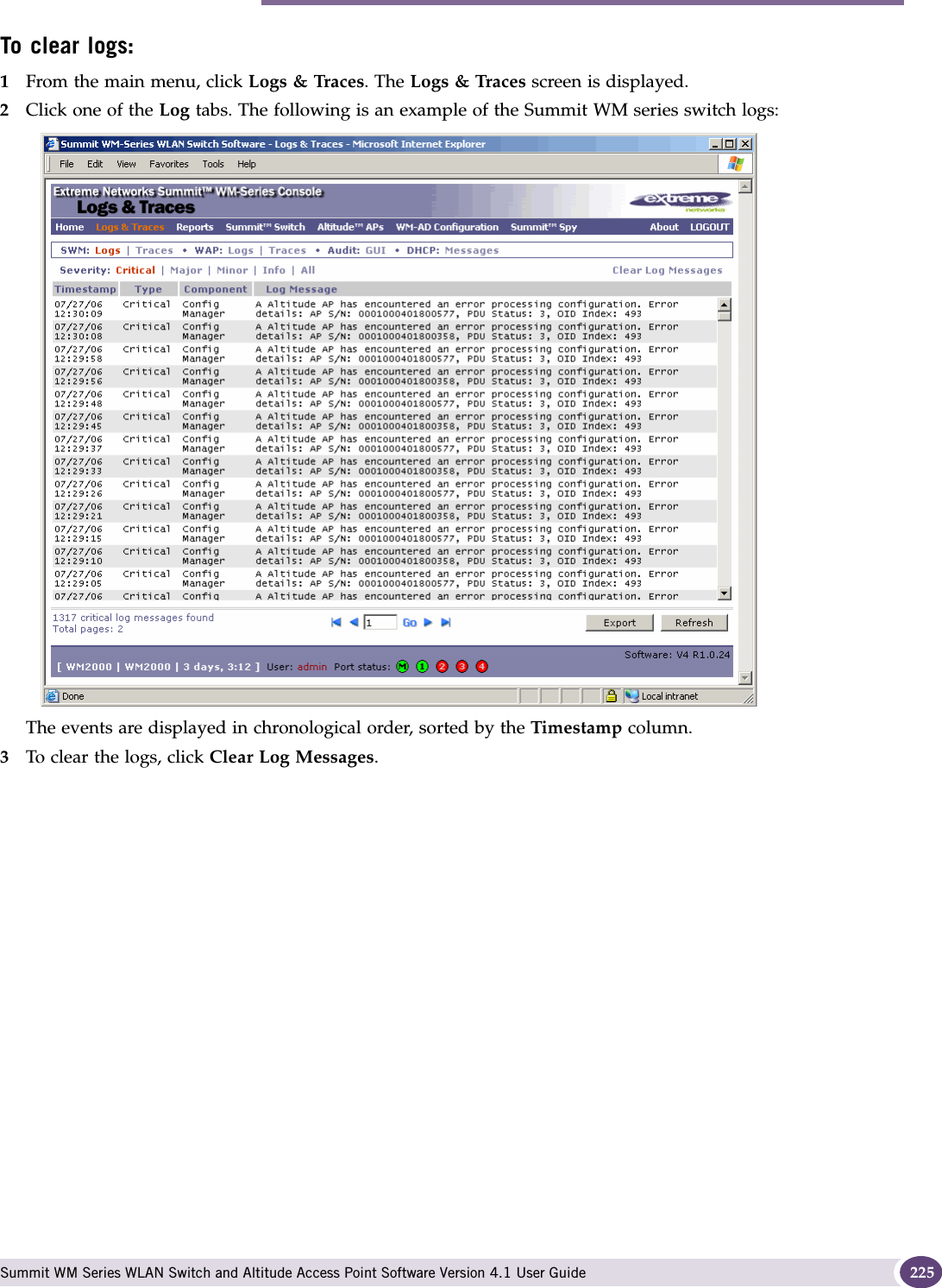
USERS MANUAL
2.
user manual 1
3.
user manual 2
user manual 2
Navigation menu
Upload a User Manual
Namespaces
Wiki Guide
HTML
PDF
Info
Views
User Manual
Discussion / Help
Navigation
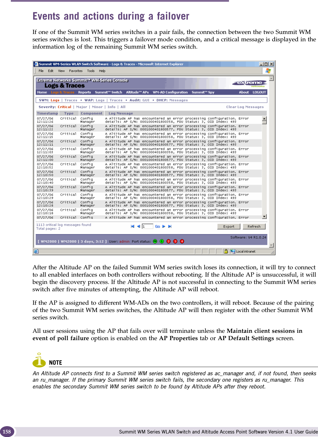
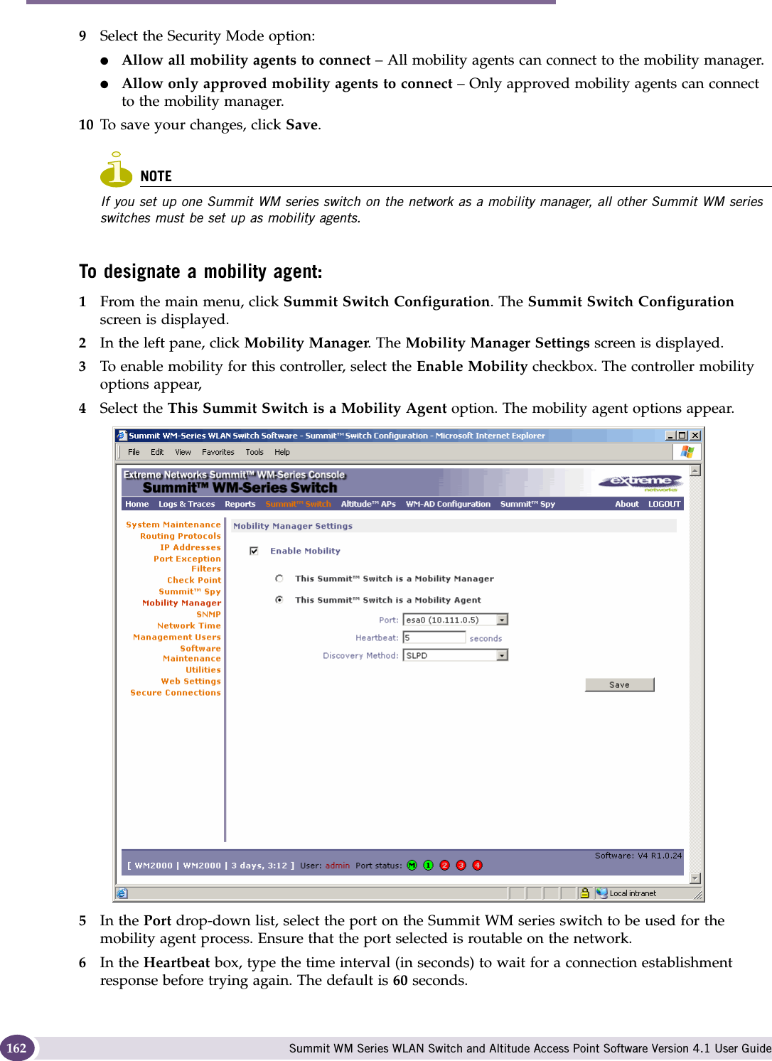
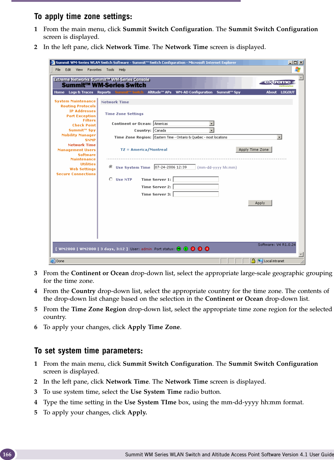
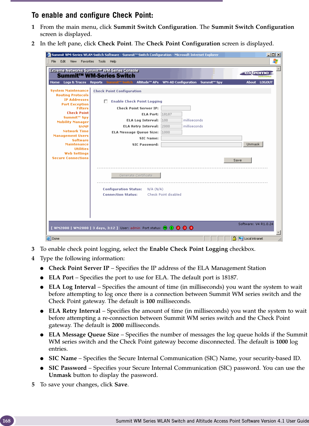
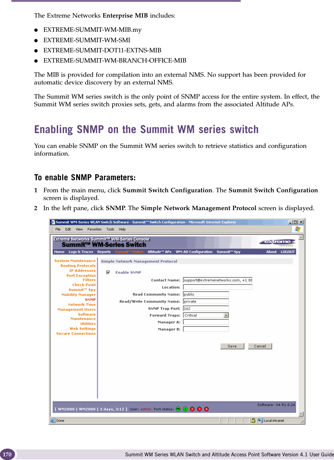

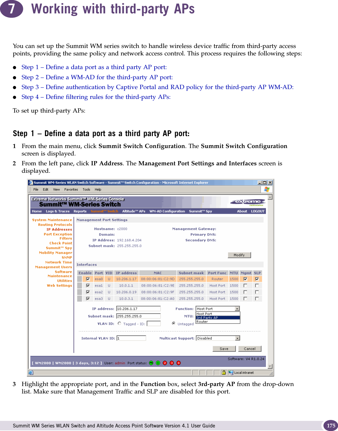
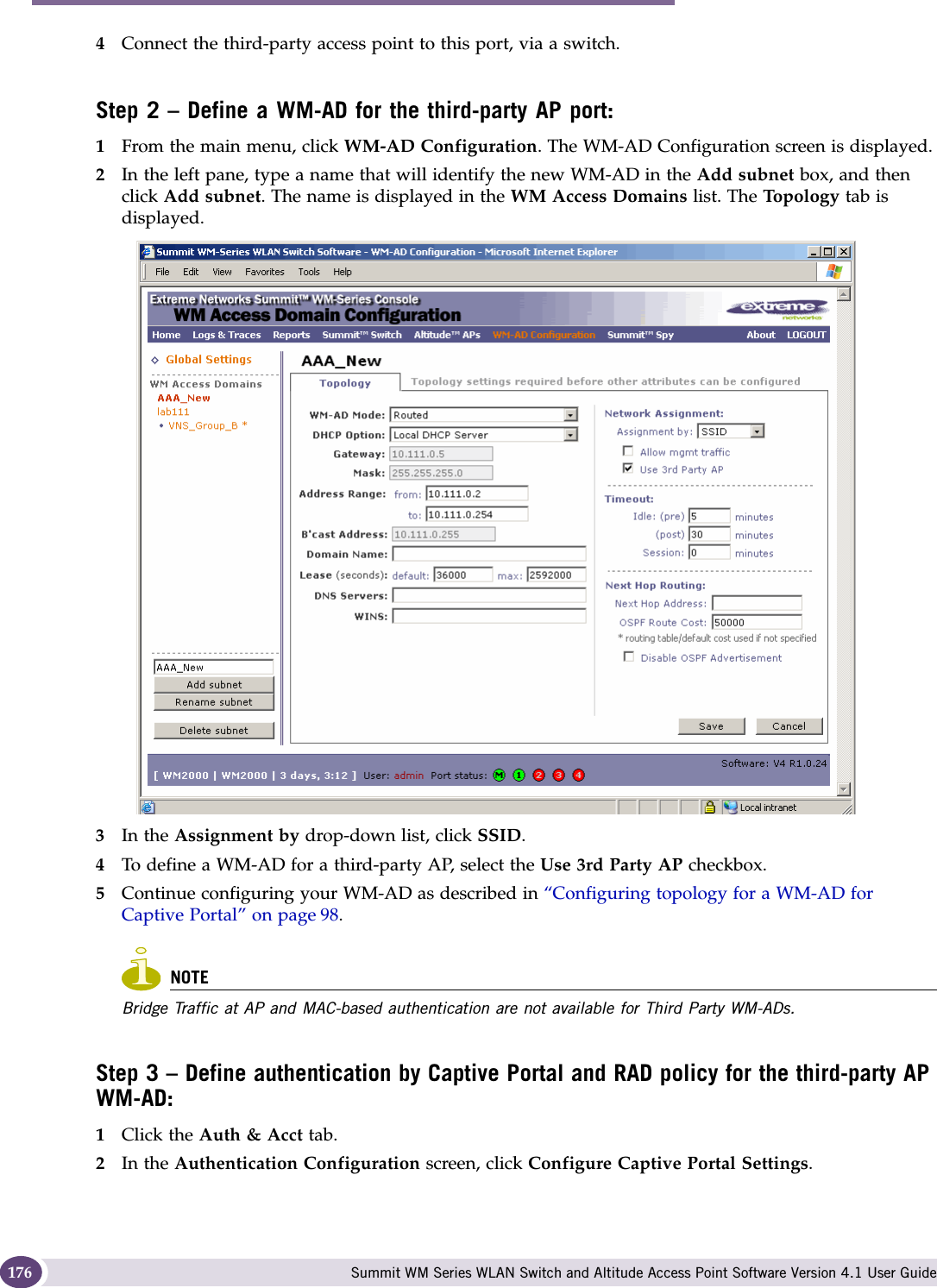

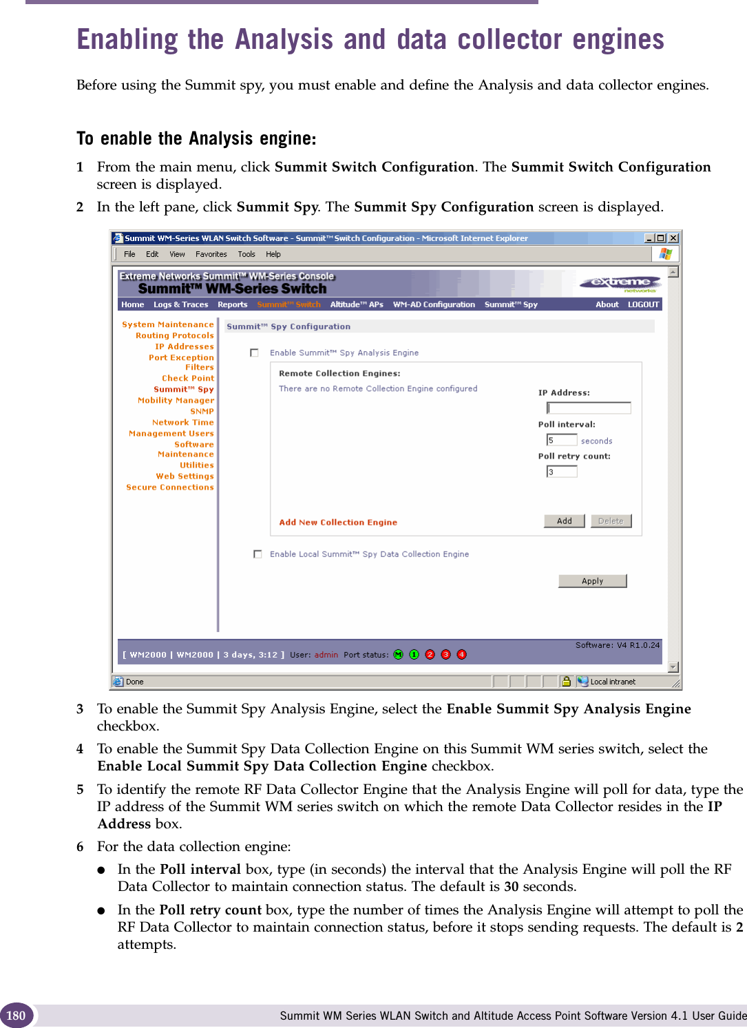
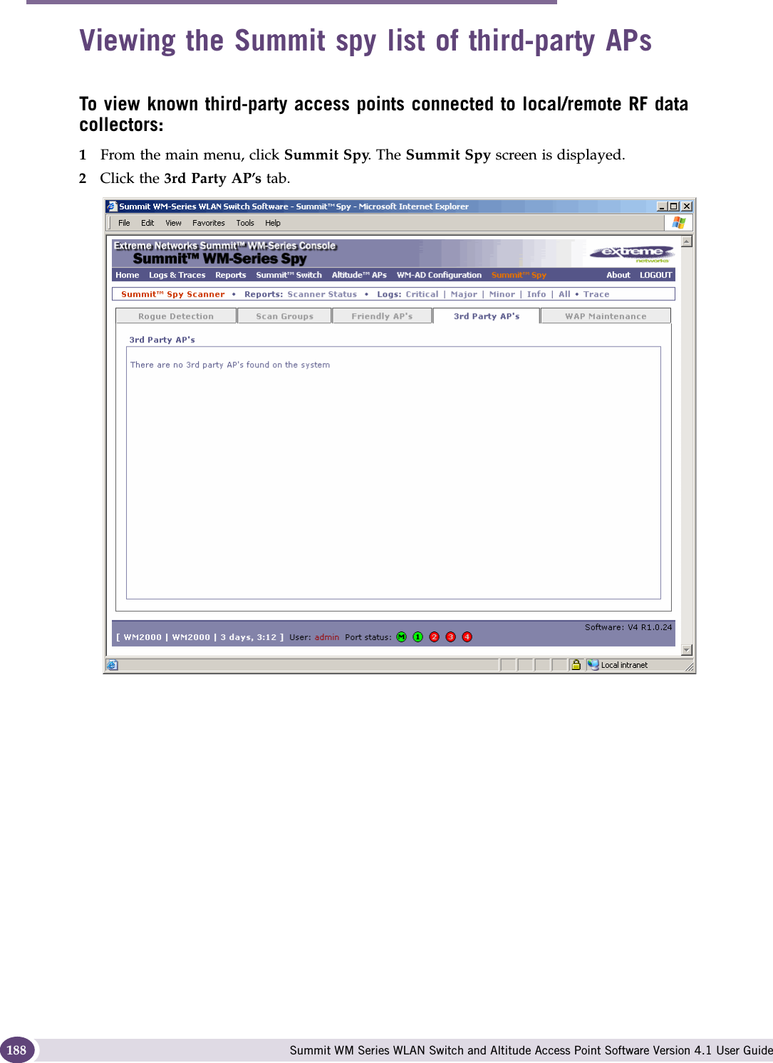
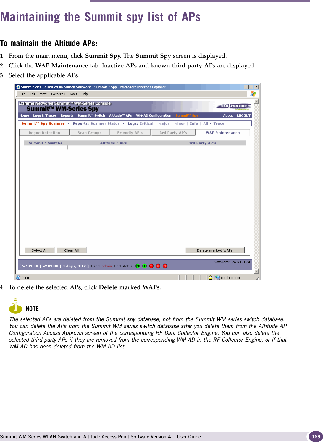
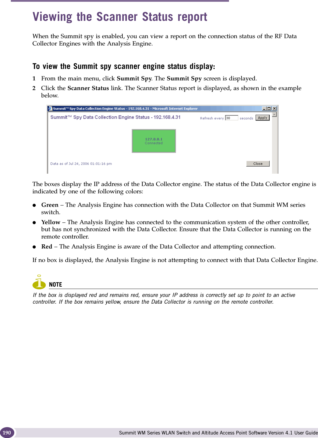
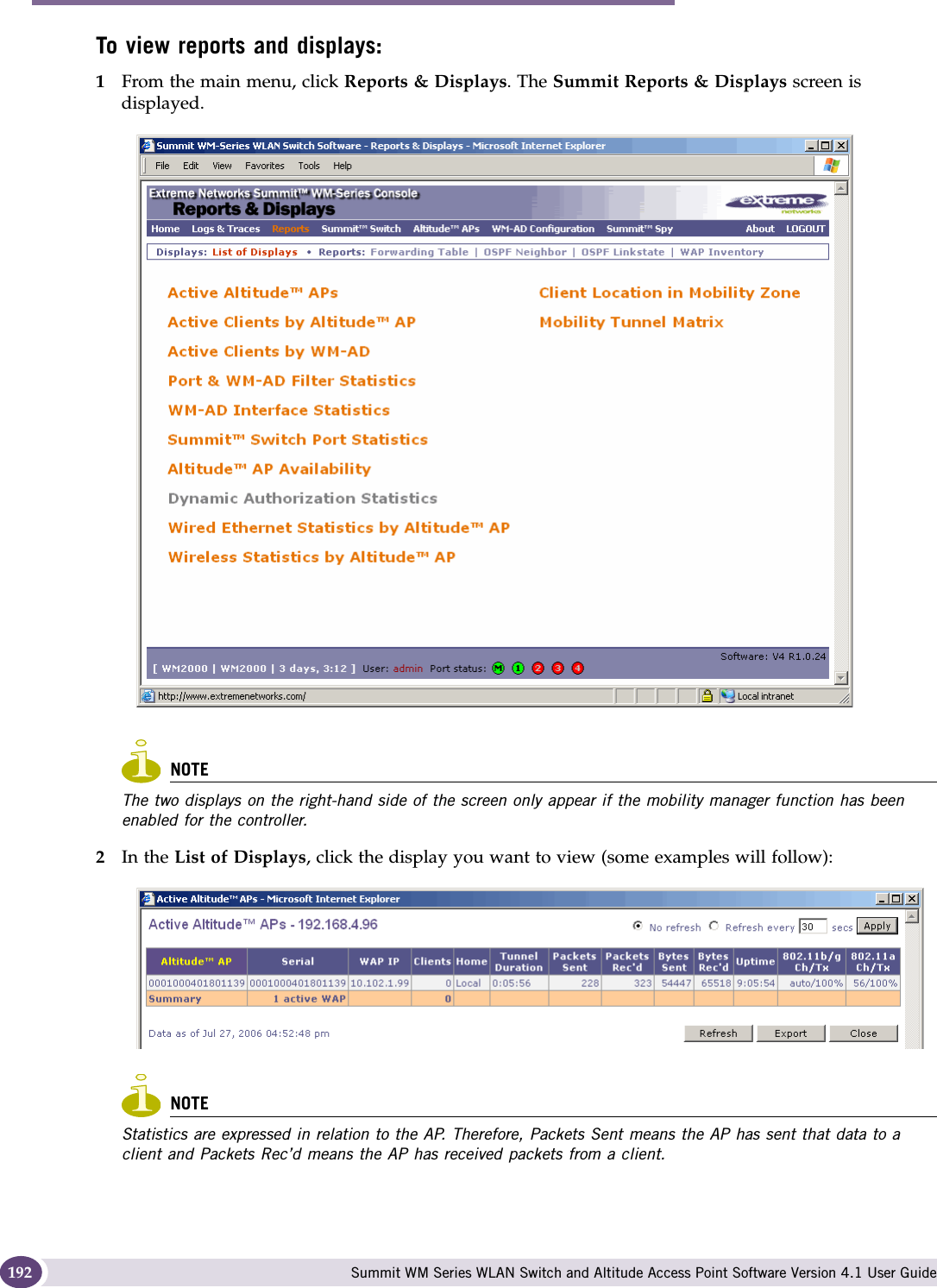
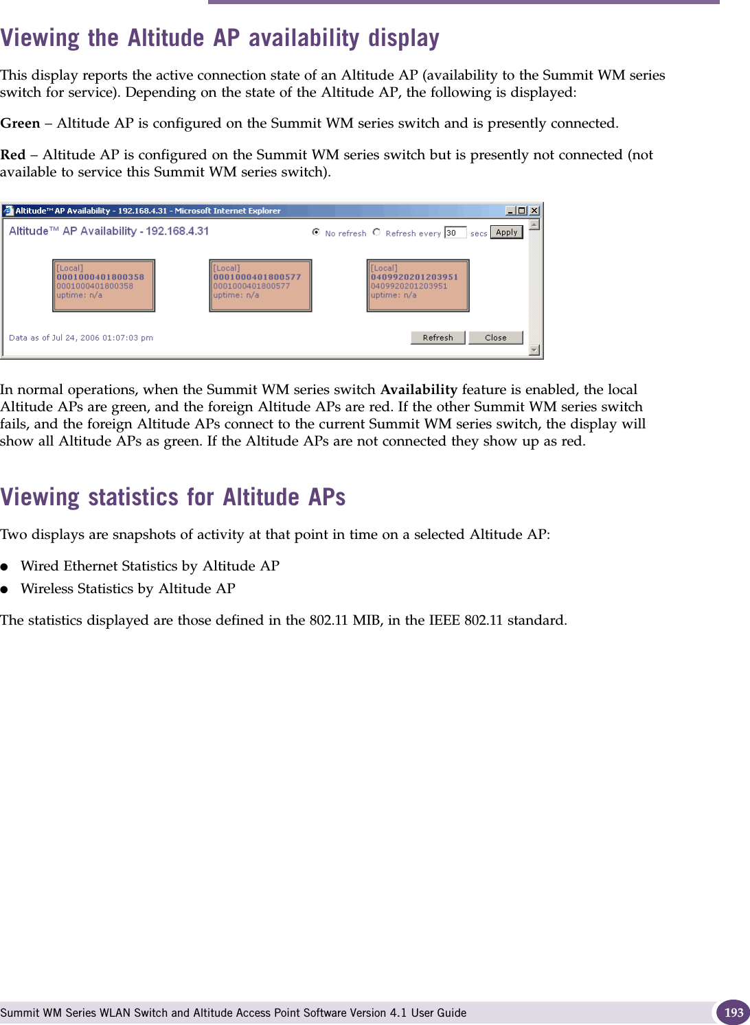
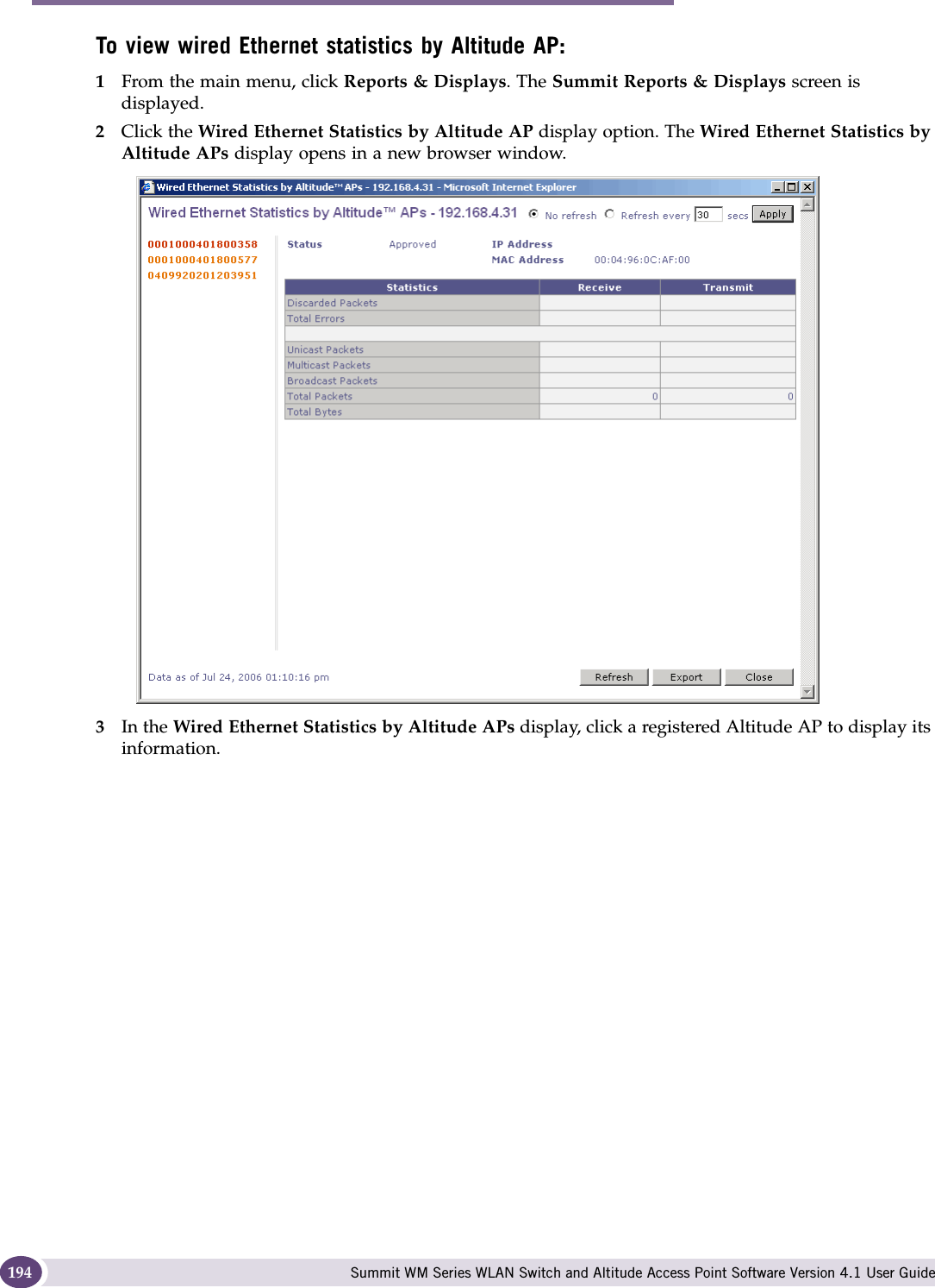
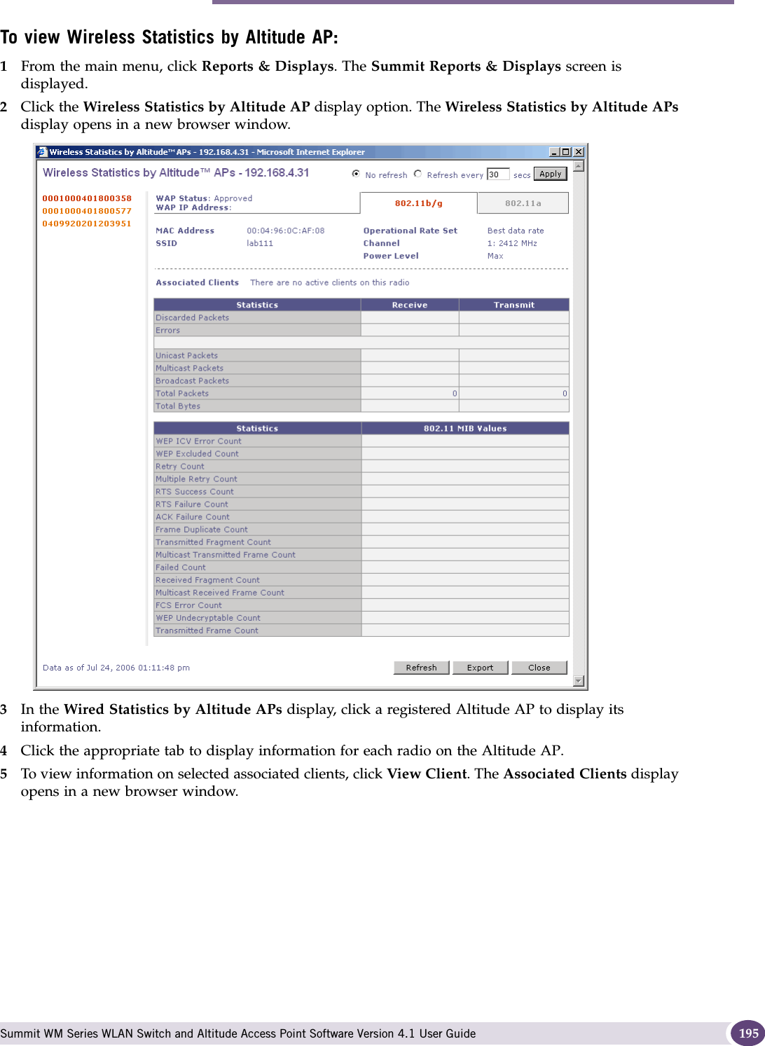
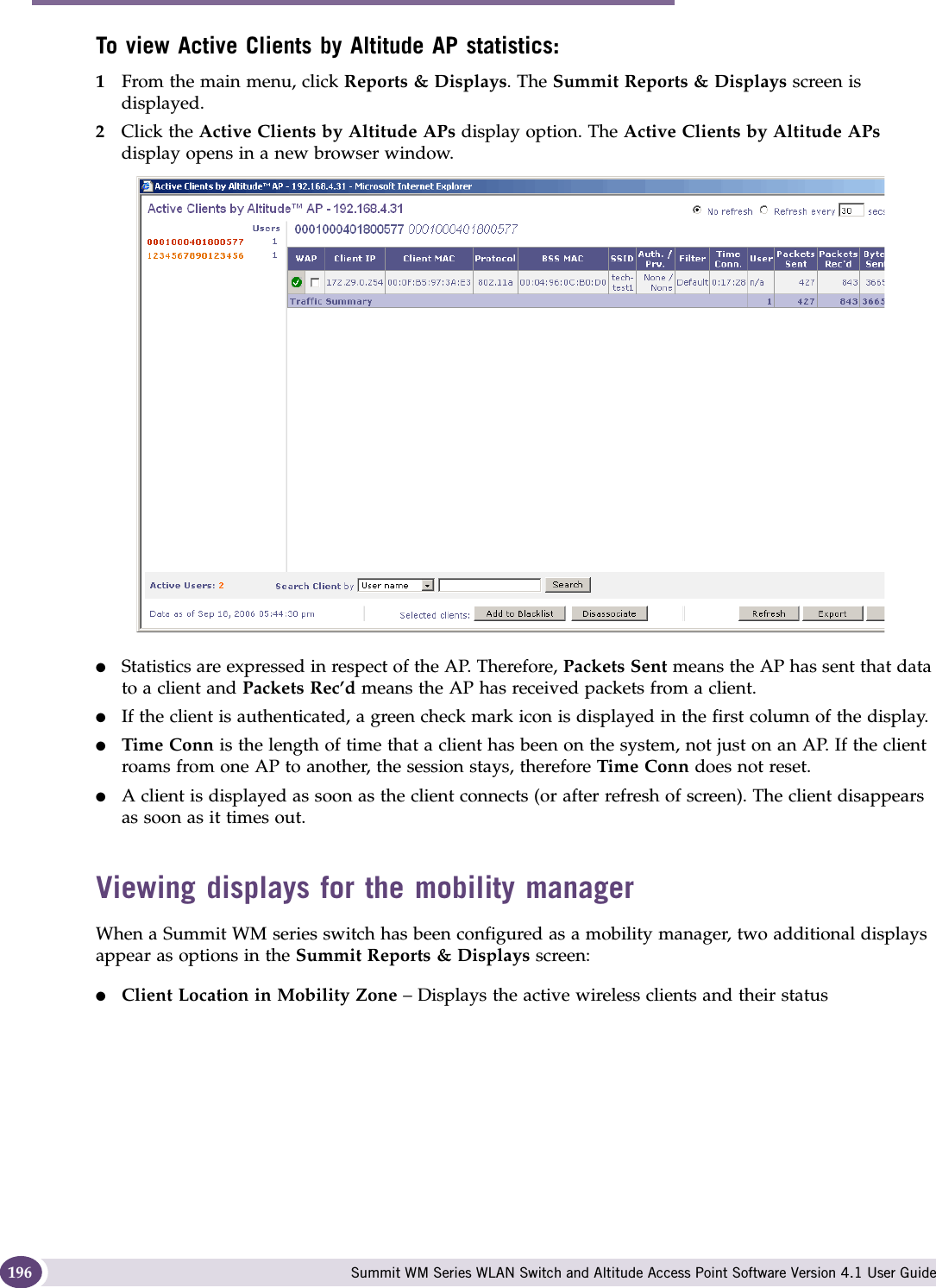
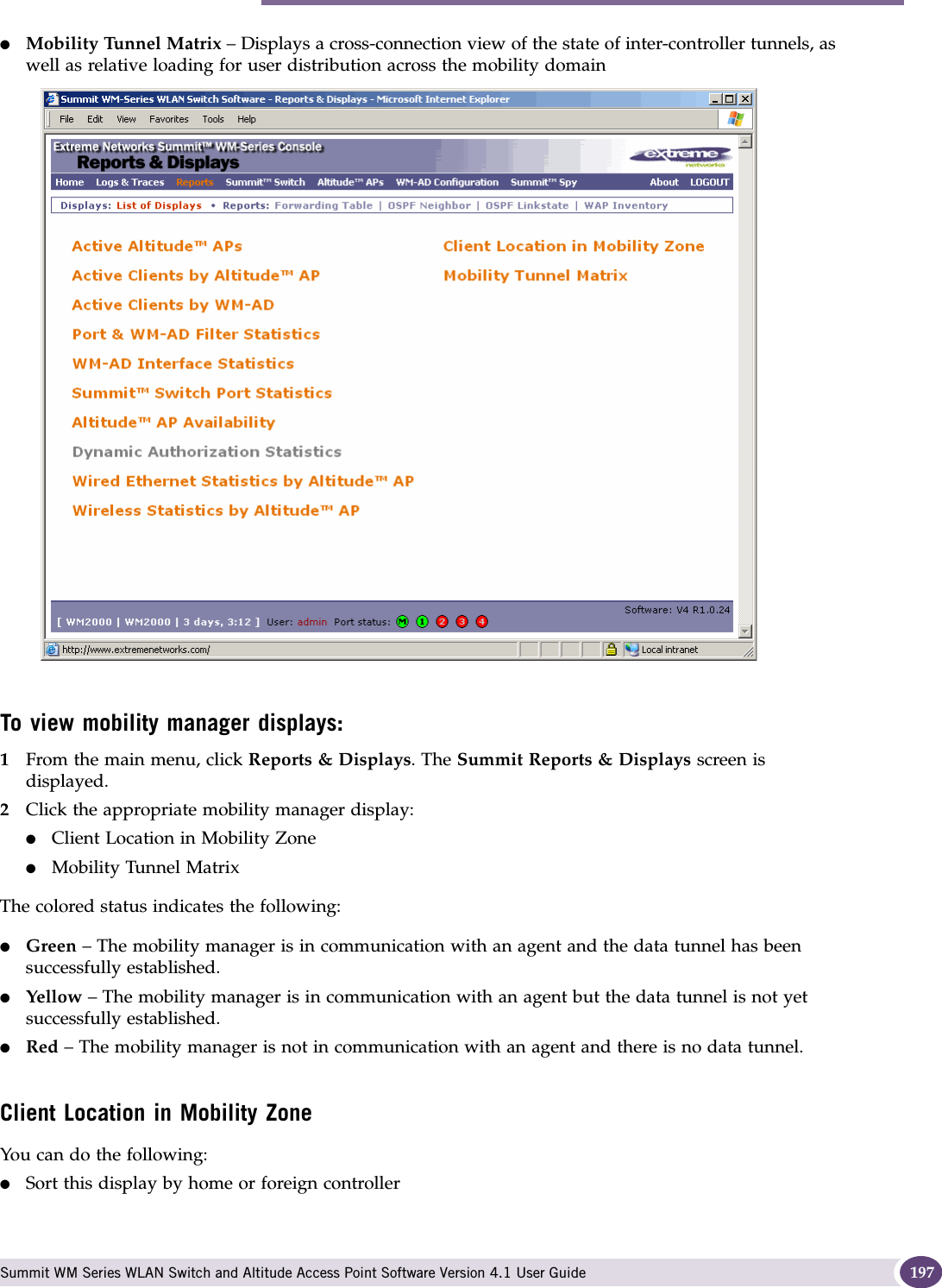
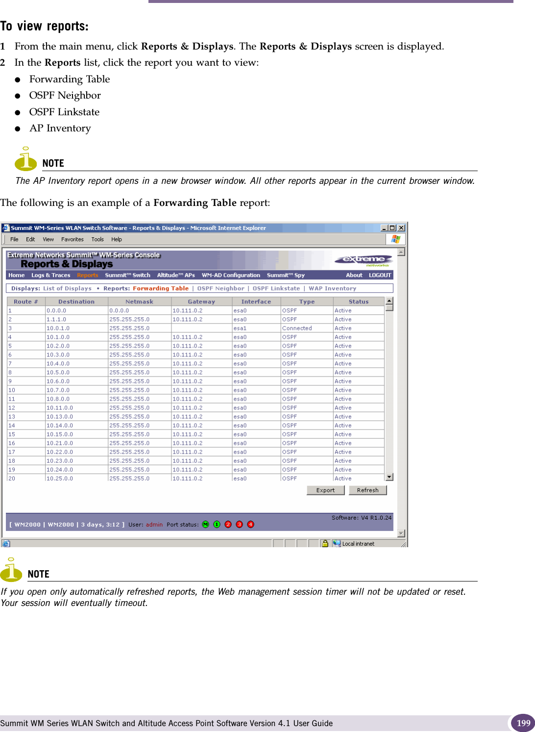
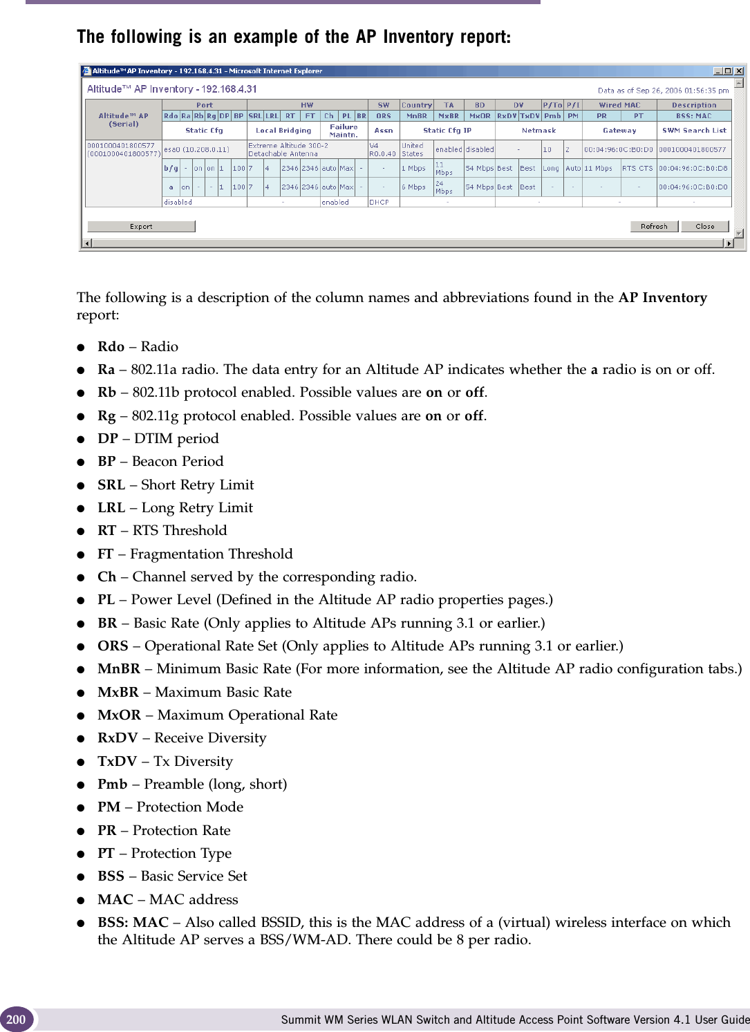

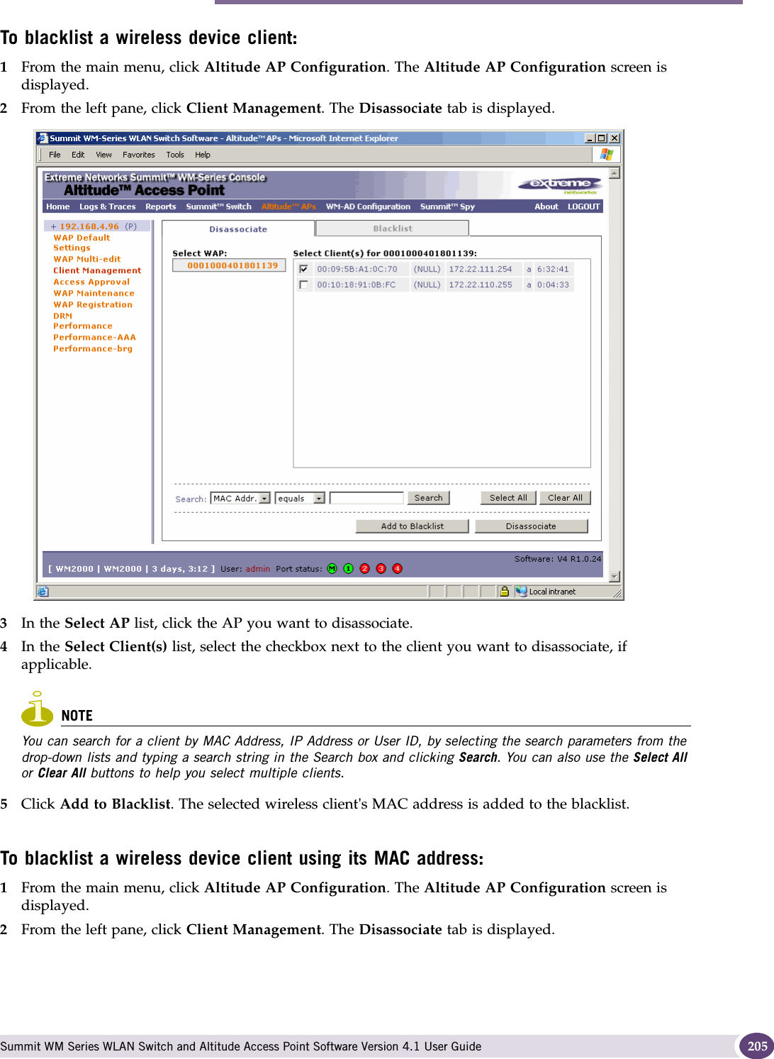
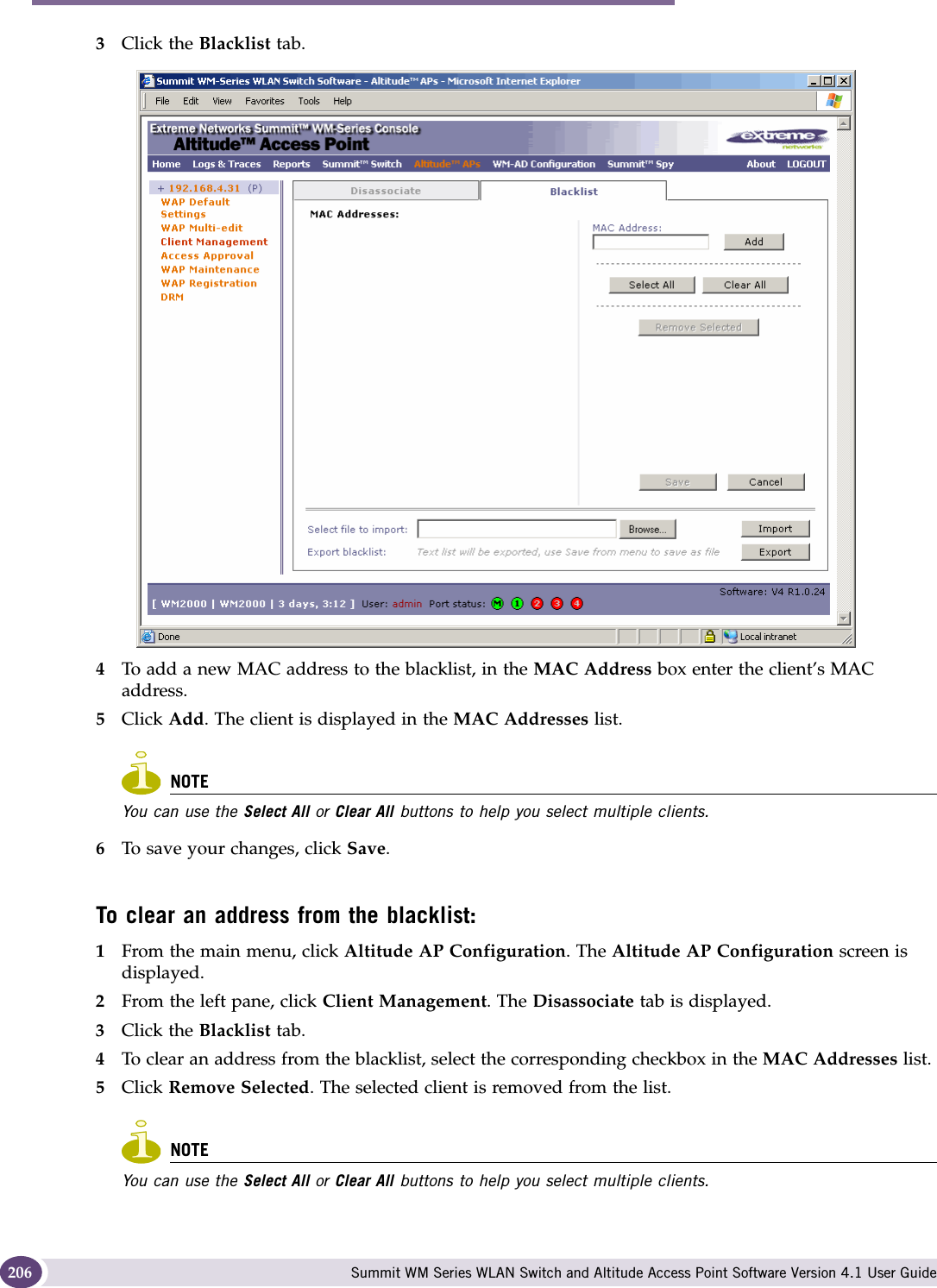
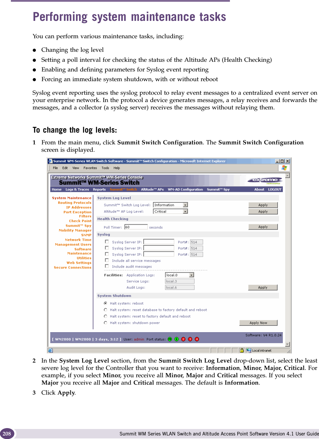
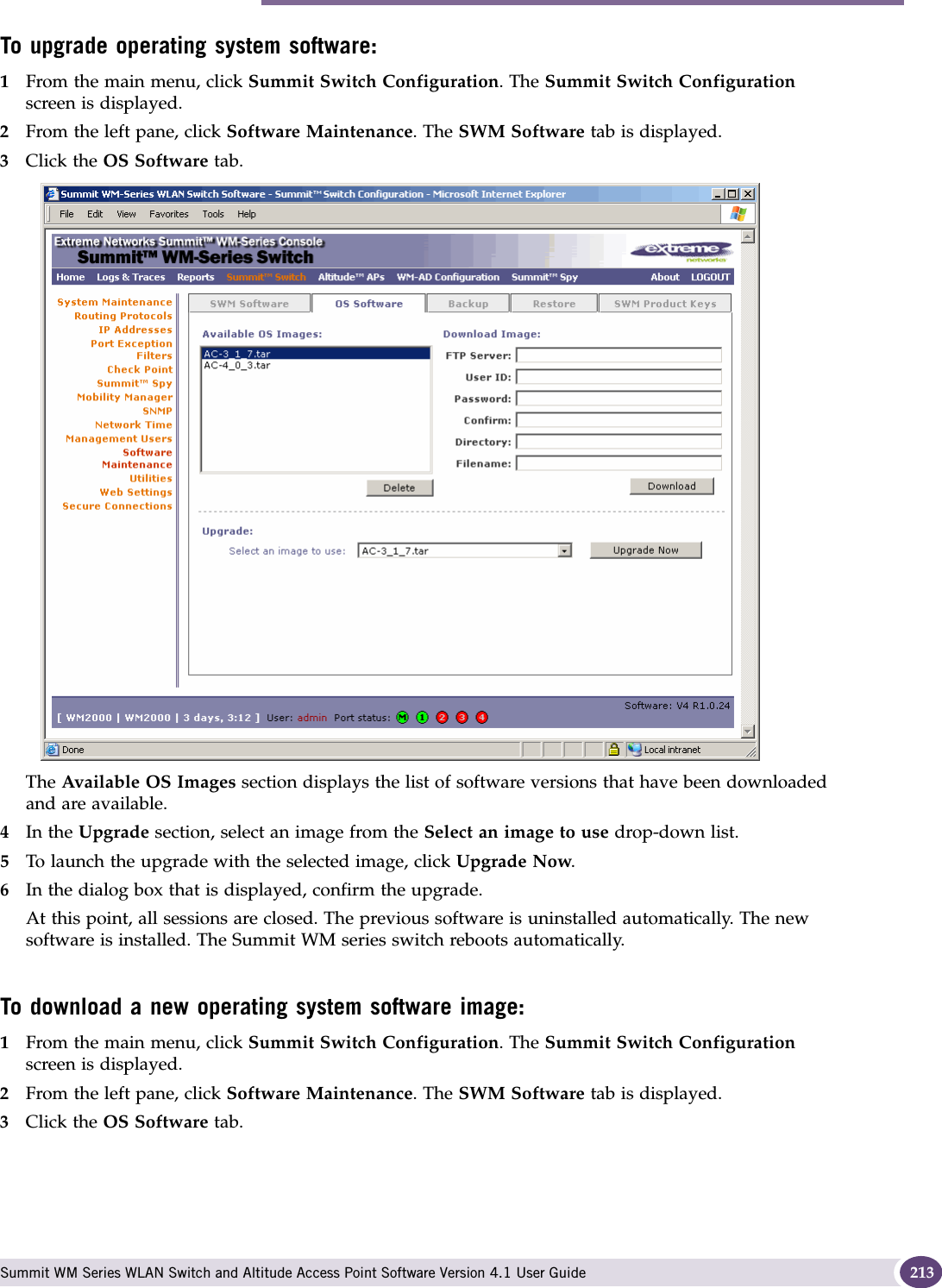
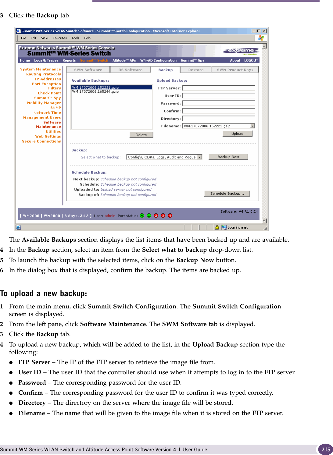
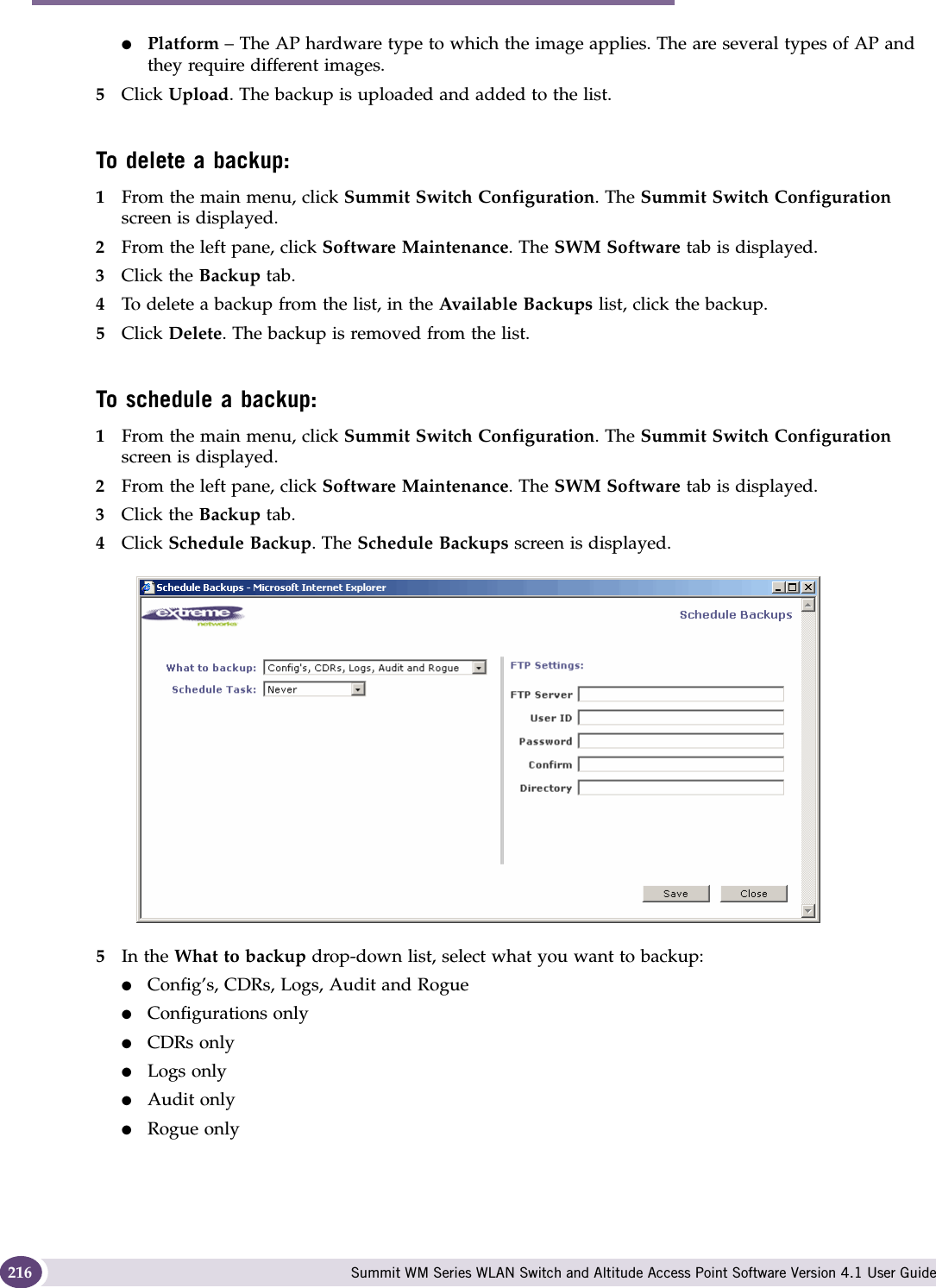

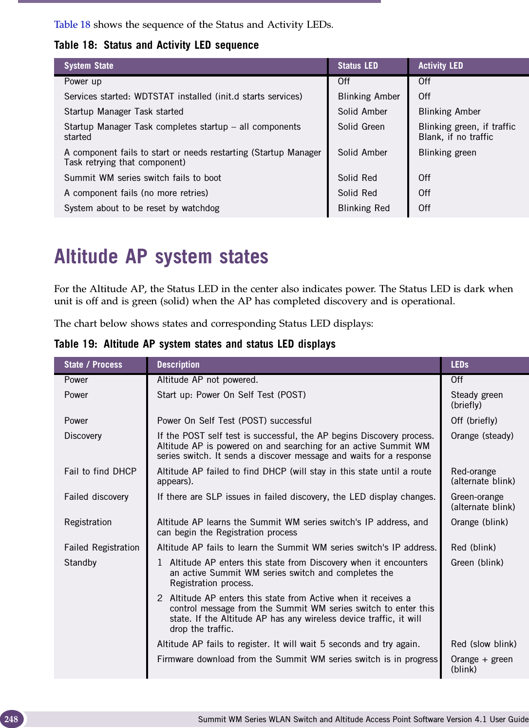
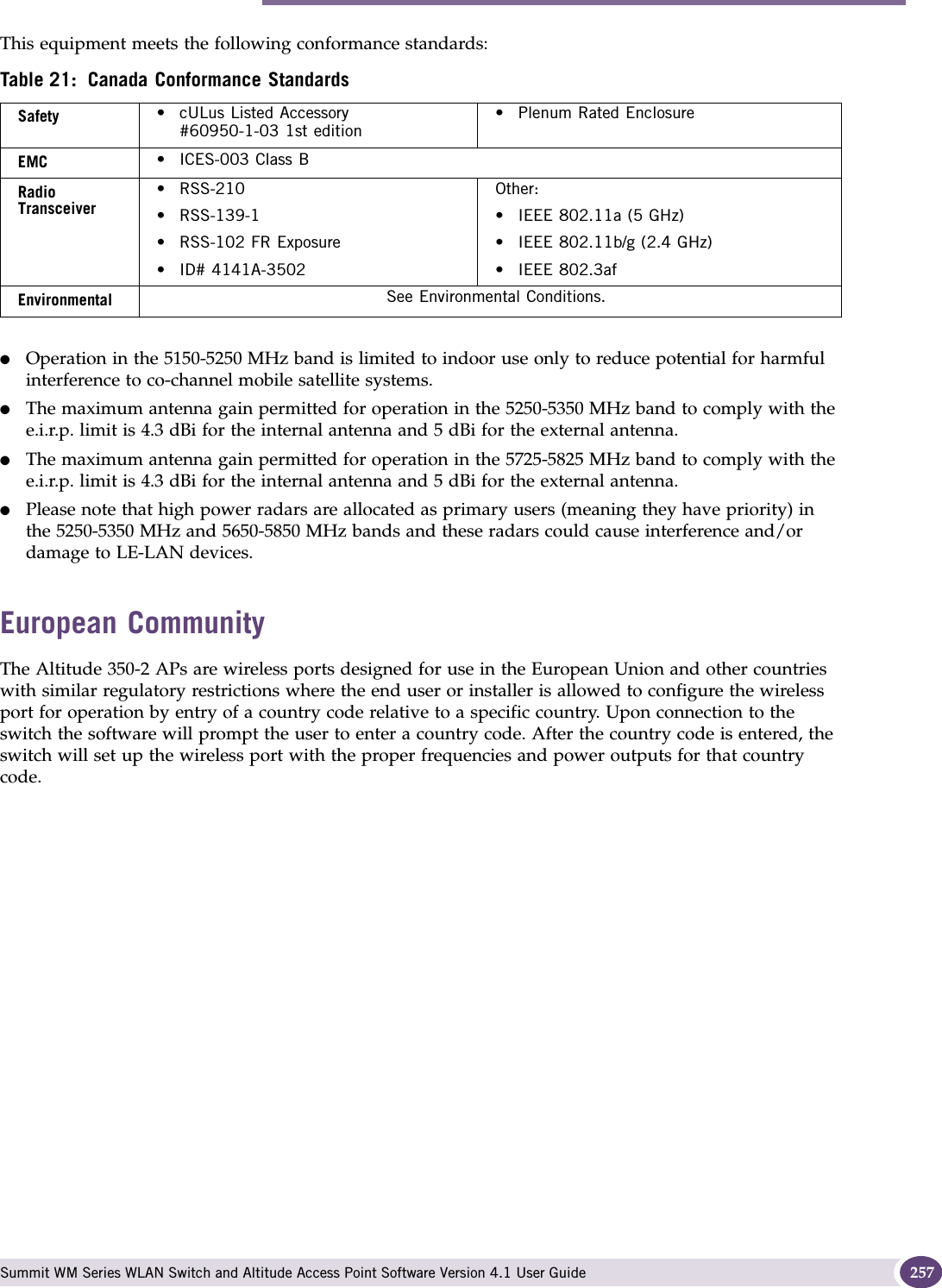
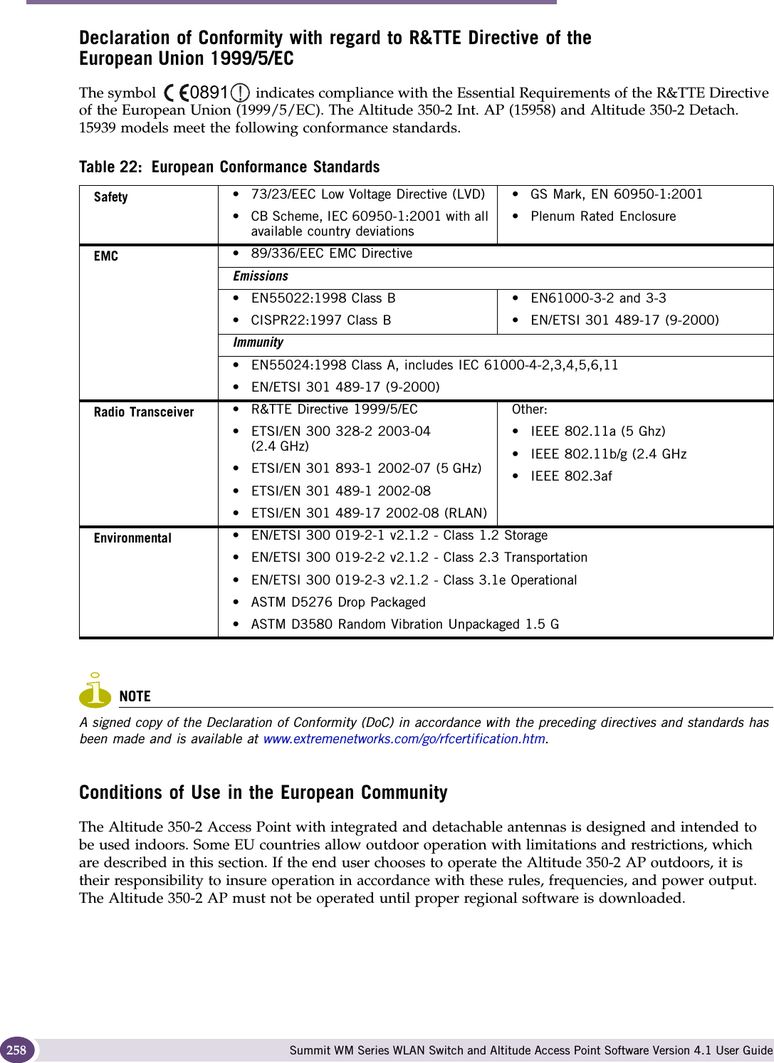
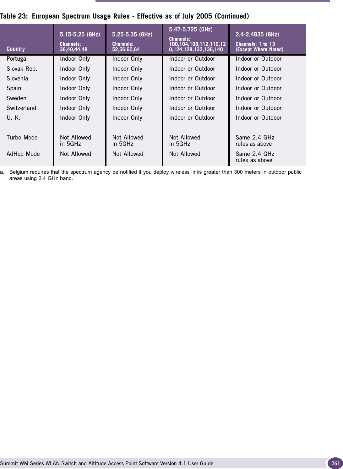
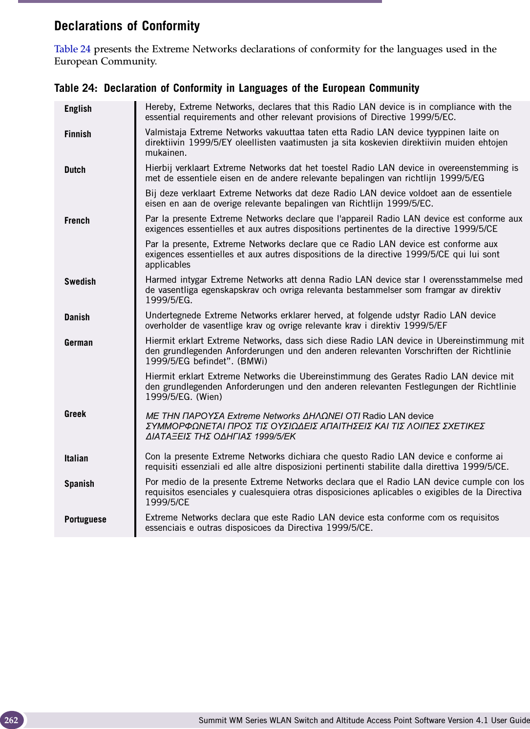
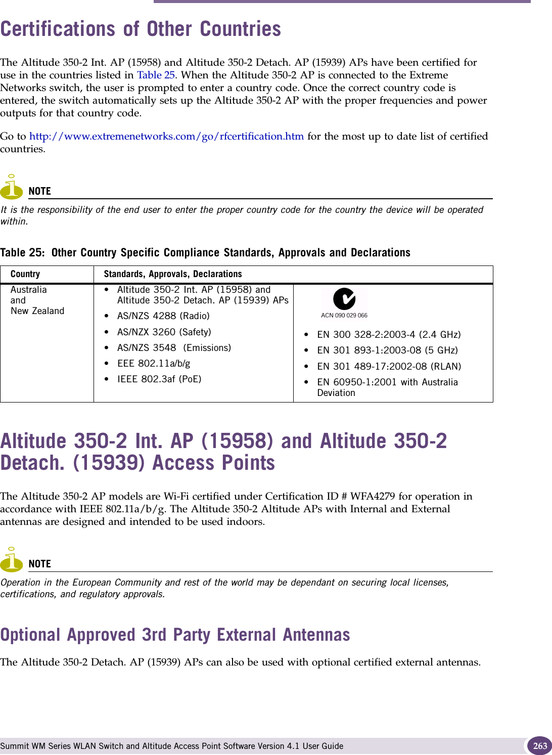
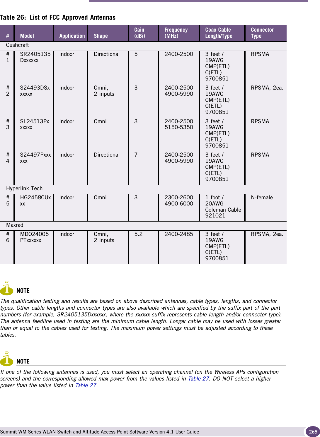
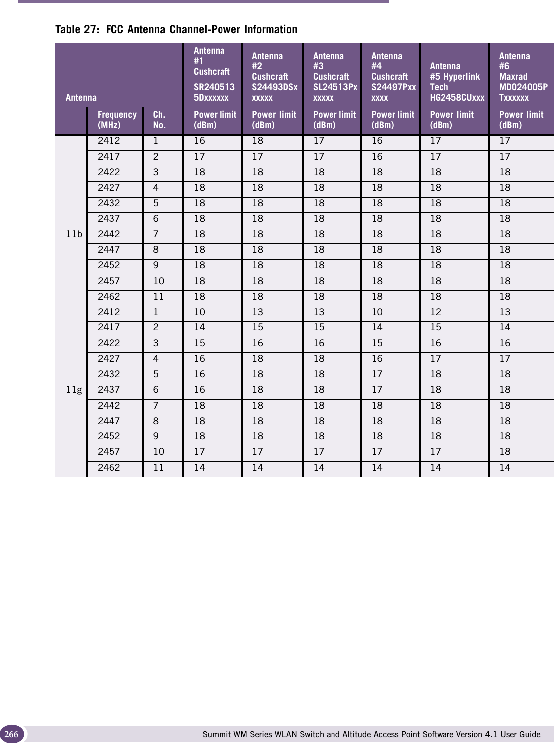
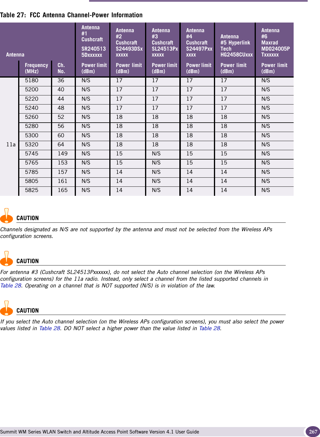
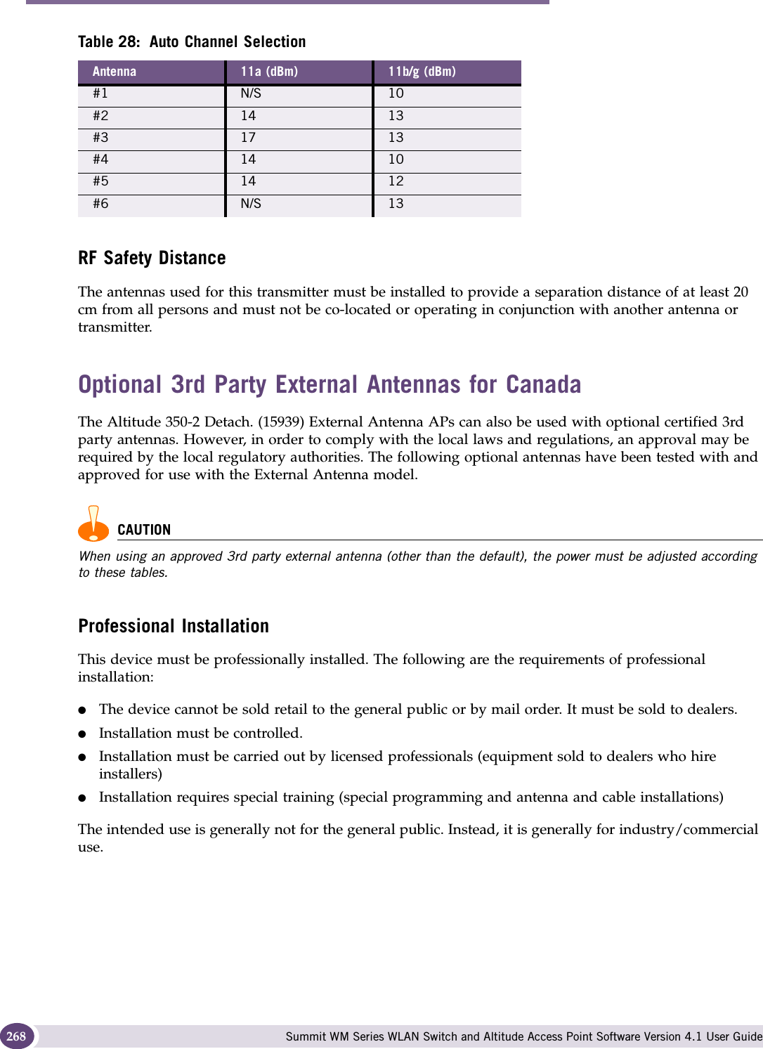
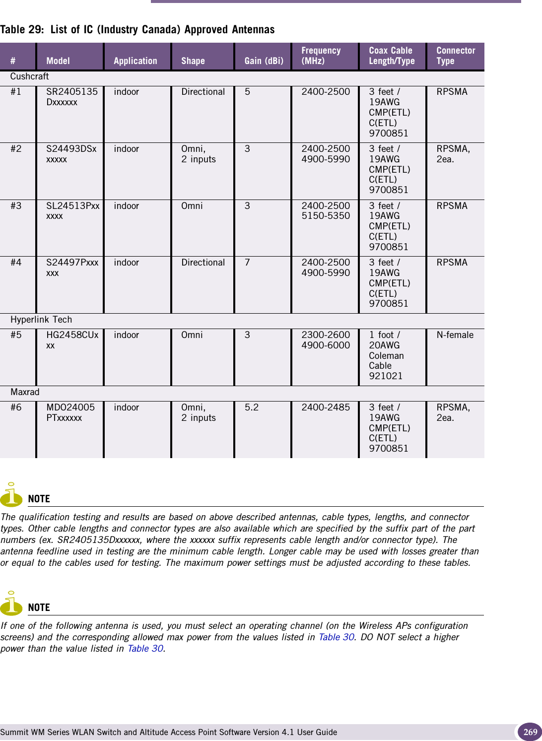
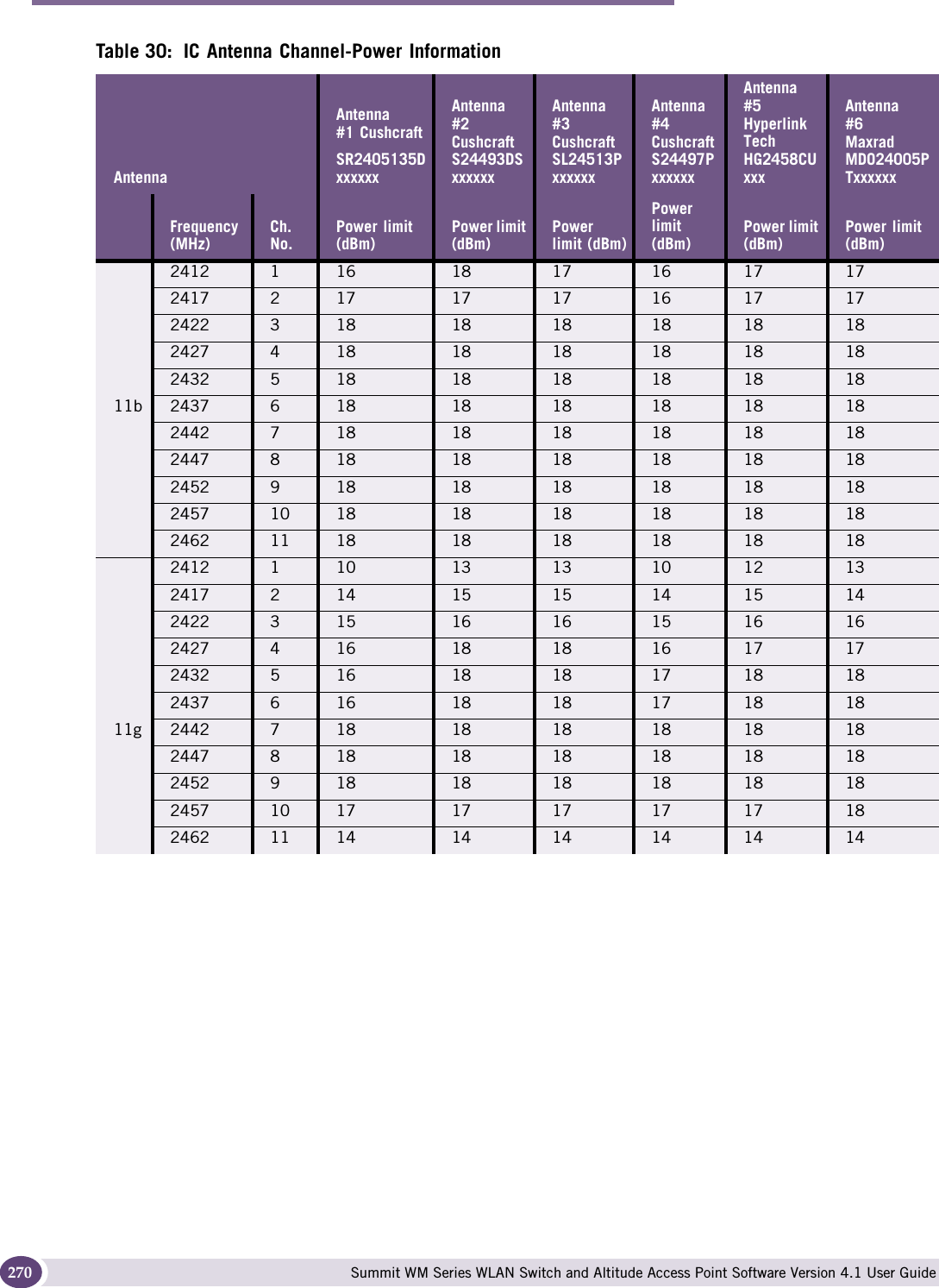
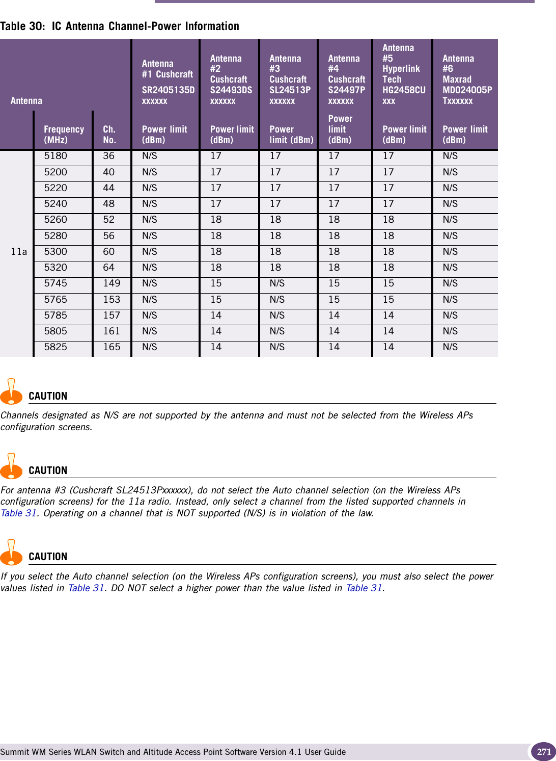
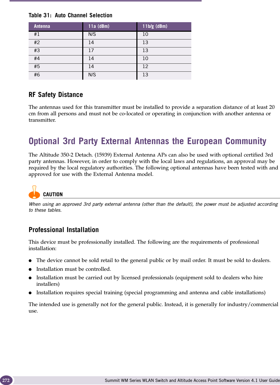
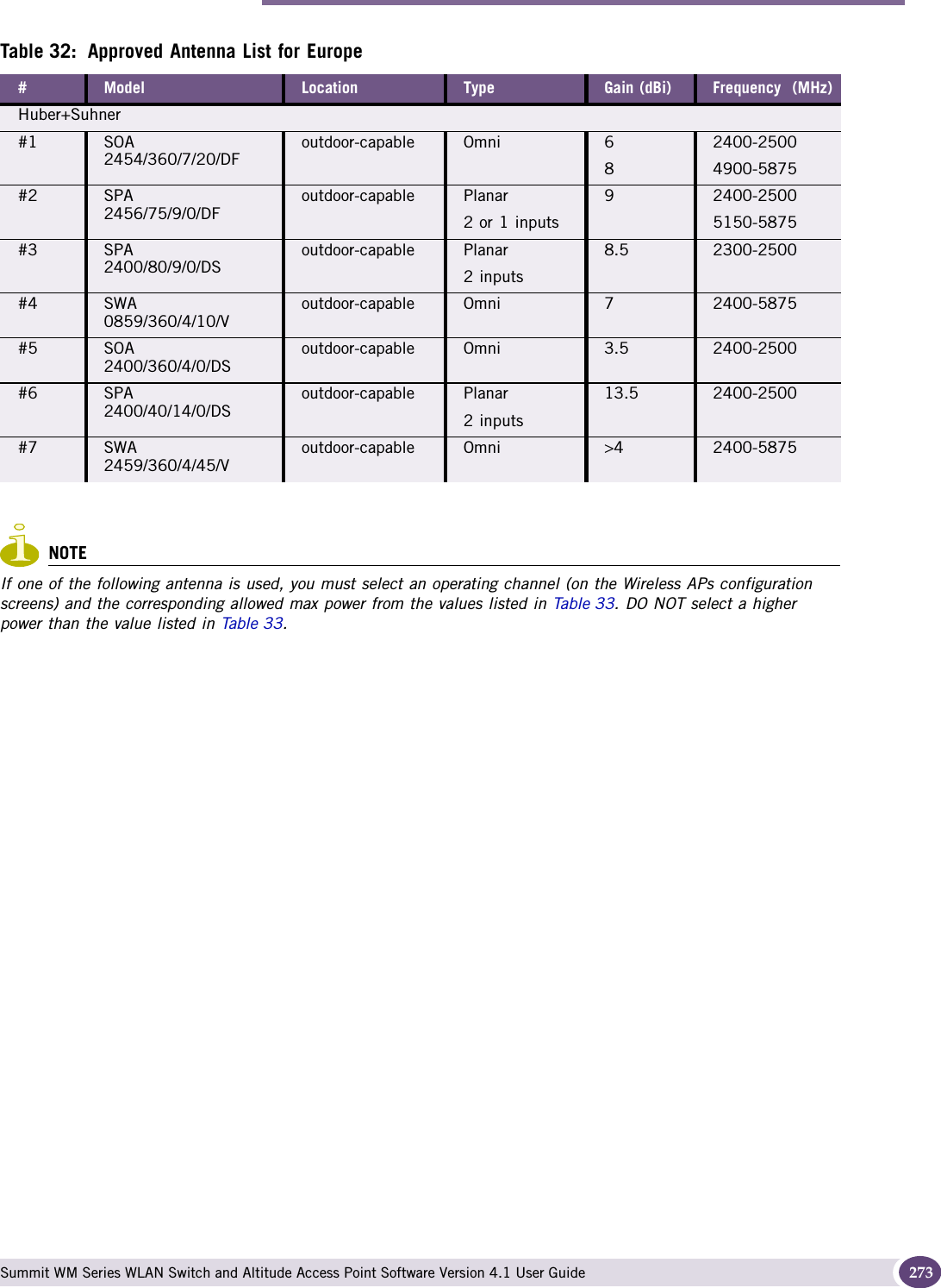
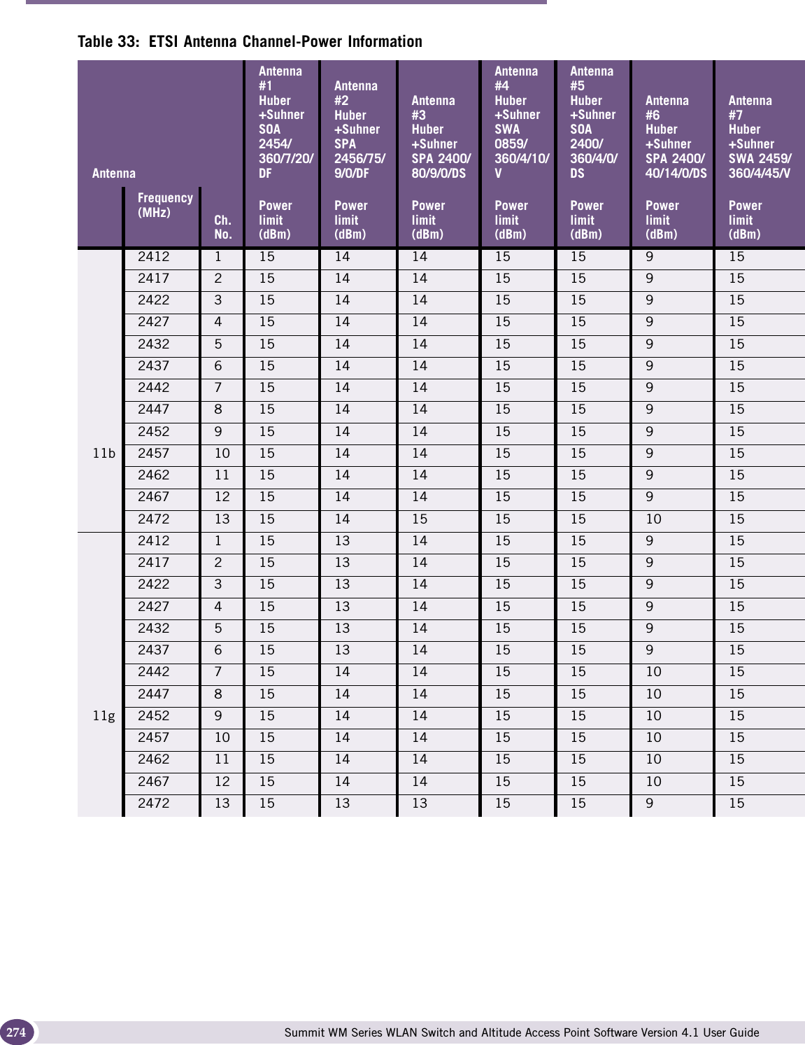
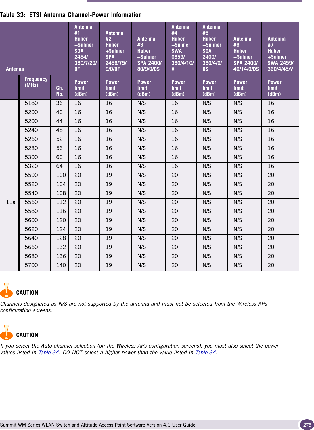
![F Summit WM Series WLAN Switch and Altitude Access Point Software Version 4.1 User Guide 231FFHSS Frequency-Hopping Spread Spectrum. A transmission technology used in Local Area Wireless Network (LAWN) transmissions where the data signal is modulated with a narrowband carrier signal that “hops” in a random but predictable sequence from frequency to frequency as a function of time over a wide band of frequencies. This technique reduces interference. If synchronized properly, a single logical channel is maintained. (Compare DSSS)Fit, thin and fat APs A thin AP architecture uses two components: an access point that is essentially a stripped-down radio and a centralized management controller that handles the other WLAN system functions. Wired network switches are also required. A fit AP, a variation of the thin AP, handles the RF and encryption, while the central management controller, aware of the wireless users' identities and locations, handles secure roaming, quality of service, and user authentication. The central management controller also handles AP configuration and management. A fat (or thick) AP architecture concentrates all the WLAN intelligence in the access point. The AP handles the radio frequency (RF) communication, as well as authenticating users, encrypting communications, secure roaming, WLAN management, and in some cases, network routing. FQDN Fully Qualified Domain Name. A “friendly” designation of a computer, of the general form computer.[subnetwork.].organization.domain. The FQDN names must be translated into an IP address in order for the resource to be found on a network, usually performed by a Domain Name Server.FTM Forwarding Table ManagerFTP File Transfer ProtocolGGateway In the wireless world, an access point with additional software capabilities such as providing NAT and DHCP. Gateways may also provide VPN support, roaming, firewalls, various levels of security, etc. Gigabit Ethernet The high data rate of the Ethernet standard, supporting data rates of 1 gigabit (1,000 megabits) per second.GUI Graphical User Interface](https://usermanual.wiki/Extreme-Networks/A3502A.user-manual-2/User-Guide-845208-Page-79.png)