Extreme Networks A3502A ALTITUDE 350-2 ACCESS POINT User Manual UserGuide
Extreme Networks ALTITUDE 350-2 ACCESS POINT UserGuide
UserManual.wiki
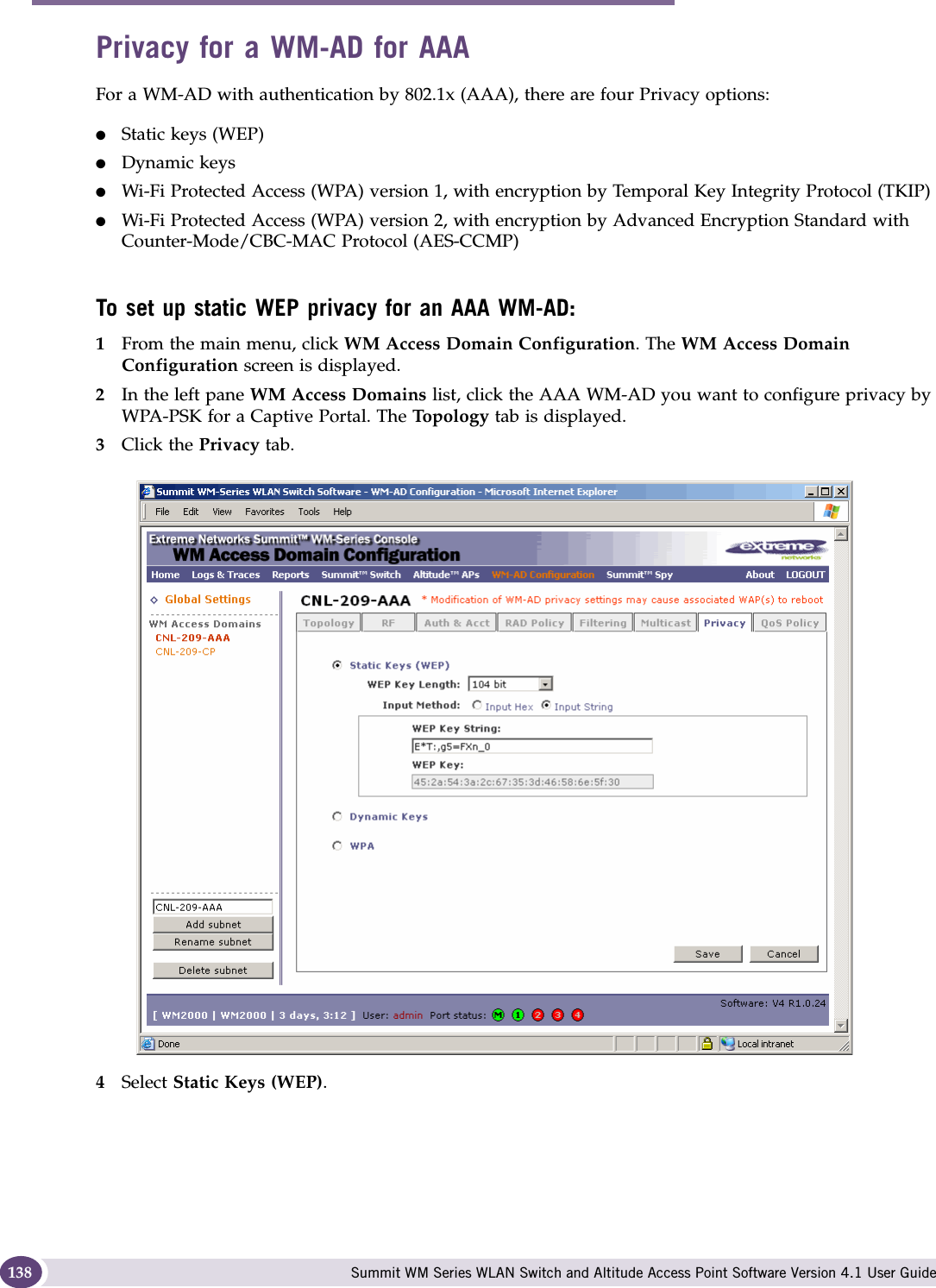
>
Extreme Networks
>
A3502A User Manual
>
user manual 1
Contents
1.
USERS MANUAL
2.
user manual 1
3.
user manual 2
user manual 1
Navigation menu
Upload a User Manual
Namespaces
Wiki Guide
HTML
PDF
Info
Views
User Manual
Discussion / Help
Navigation

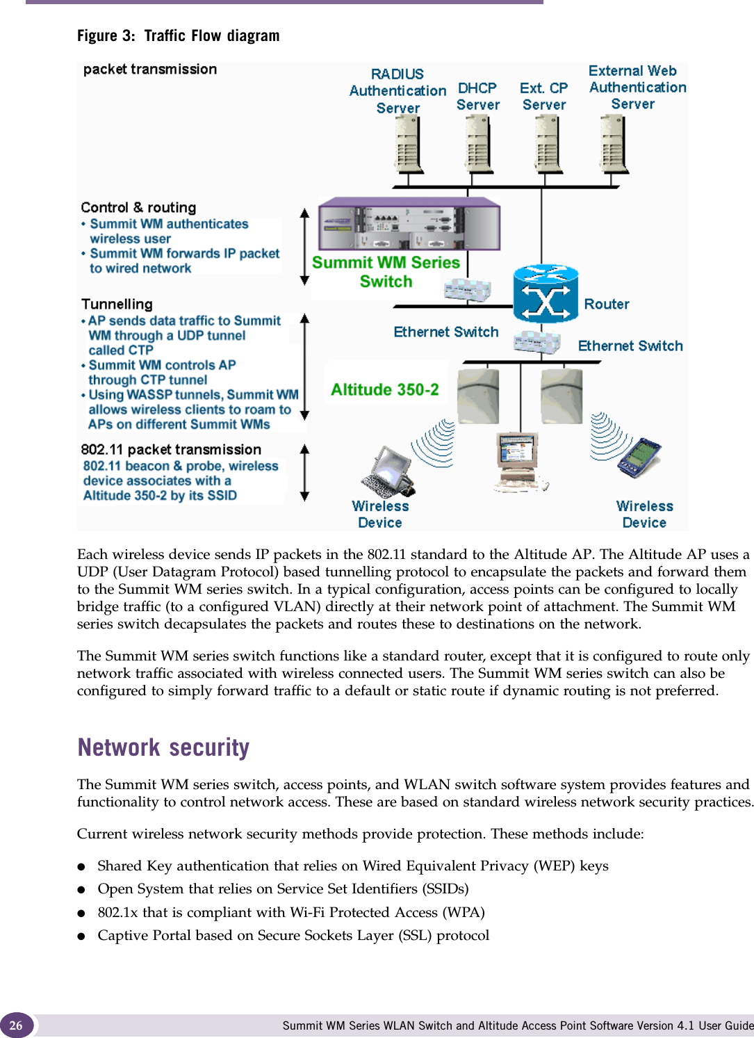
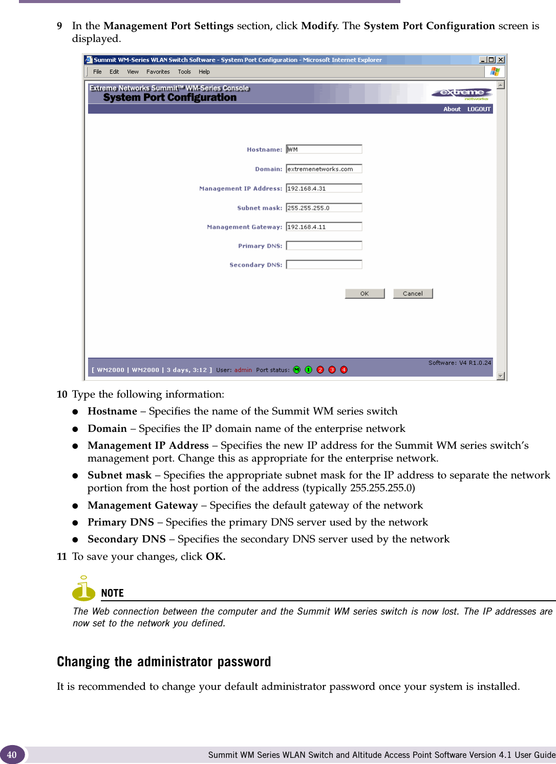
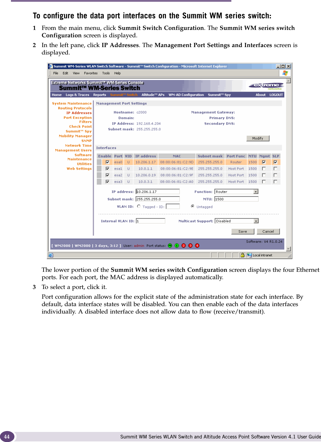
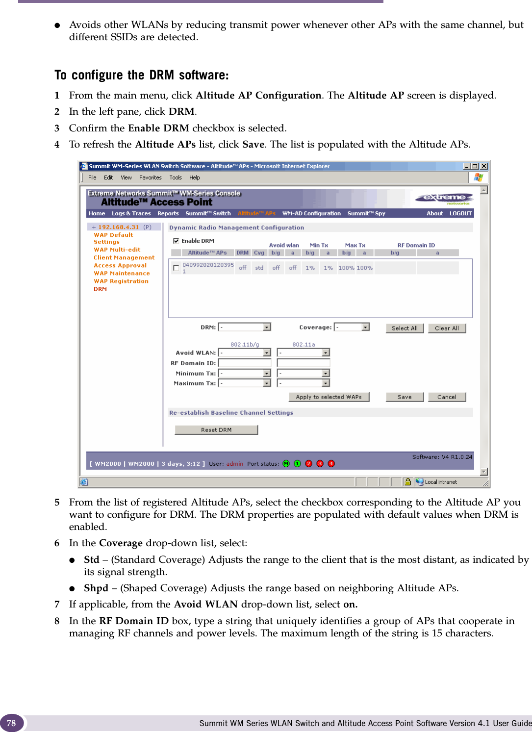
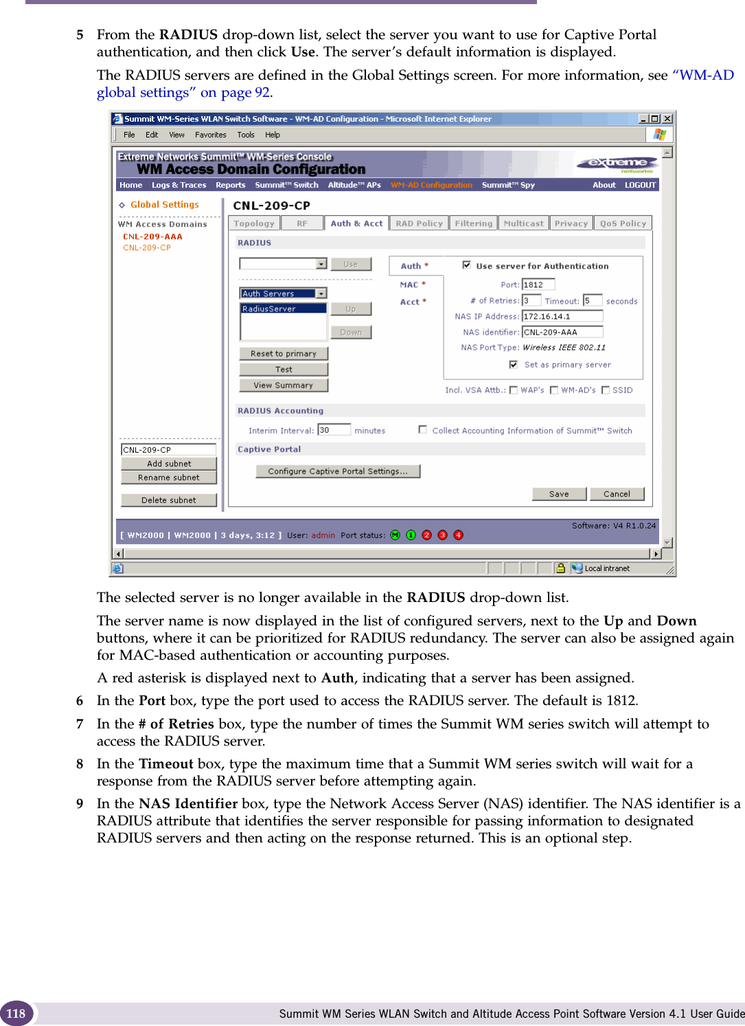
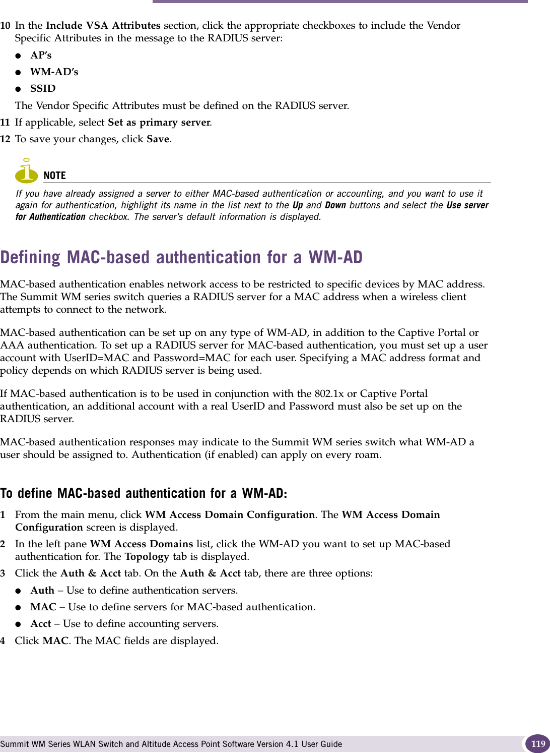
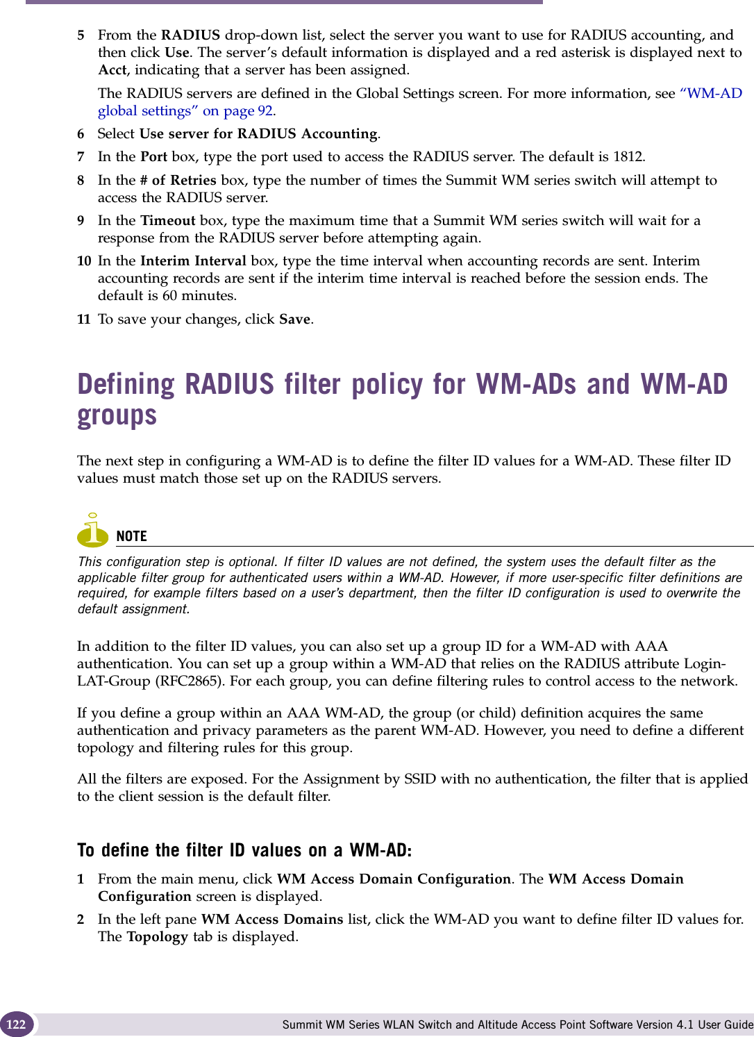
![About this Guide Summit WM Series WLAN Switch and Altitude Access Point Software Version 4.1 User Guide10●Chapter 9 describes the various reports and displays available in the Summit WM series switch, access points, and WLAN switch software system.●Chapter 10 describes maintenance activities, such as software upgrades on both the Summit WM series switch and the Altitude AP. This chapter also includes information on the logs, traces, reports and displays available.●Glossary contains a list of terms and definitions for the Summit WM series switch and the Altitude AP as well as standard industry terms used in this guide.●Appendix A provides a reference on the LED displays and their significance.●Appendix B provides the regulatory information for the Summit series switches and the Altitude 350-2 wireless access points (APs).Formatting conventionsThe Summit WM series switch, access points, and WLAN switch software documentation uses the following formatting conventions to make it easier to find information and follow procedures:●Bold text is used to identify components of the management interface, such as menu items and section of pages, as well as the names of buttons and text boxes.●For example: Click Logout.●Monospace font is used in code examples and to indicate text that you type.●For example: Type https://<wm100-address>[:mgmt-port>]●The following symbols are used to draw your attention to additional information:NOTENotes identify useful information that is not essential, such as reminders, tips, or other ways to perform a task.WARNING!Warnings identify information that is essential. Ignoring a warning can adversely affect the operation of your equipment or software.Documentation feedbackIf you have any problems using this document, please contact your next level of support:●Customers should contact the Extreme Networks Technical Assistance Center (TAC).When you call, please have the following information ready. This will help us to identify the document that you are referring to.●Title: Summit WM Series WLAN Switch and Altitude Access Point Software Version 4.1 User Guide ●Part Number: 120369-00](https://usermanual.wiki/Extreme-Networks/A3502A.user-manual-1/User-Guide-845207-Page-10.png)


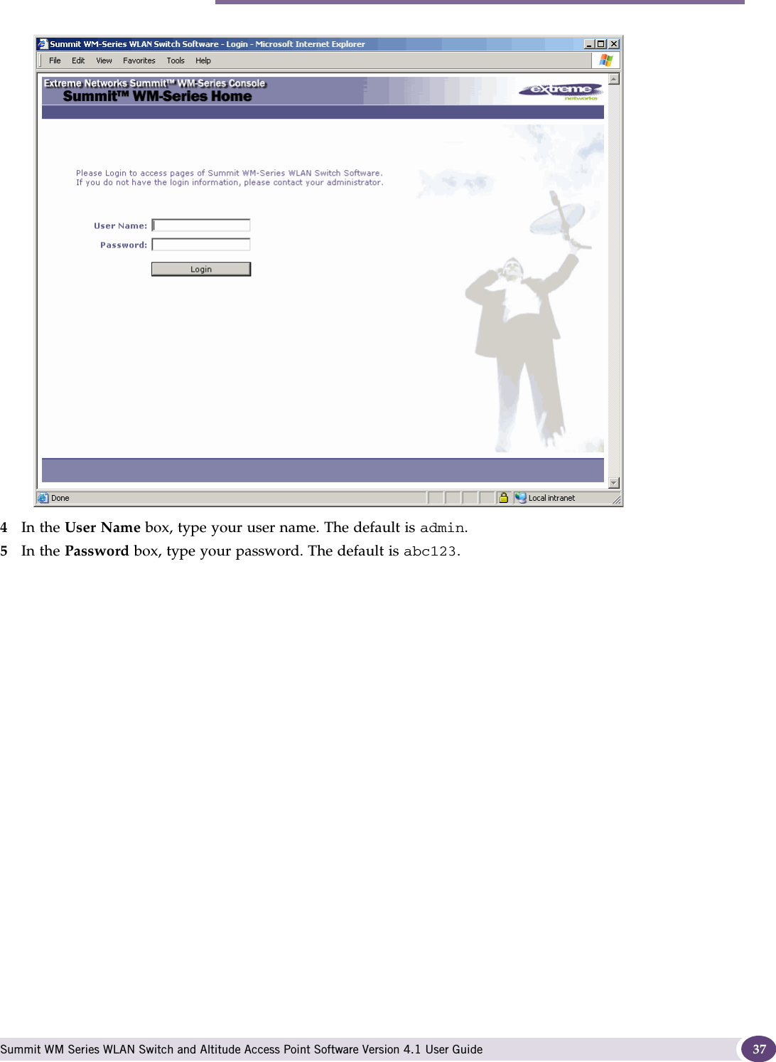
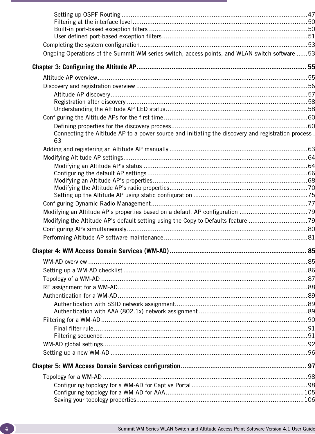
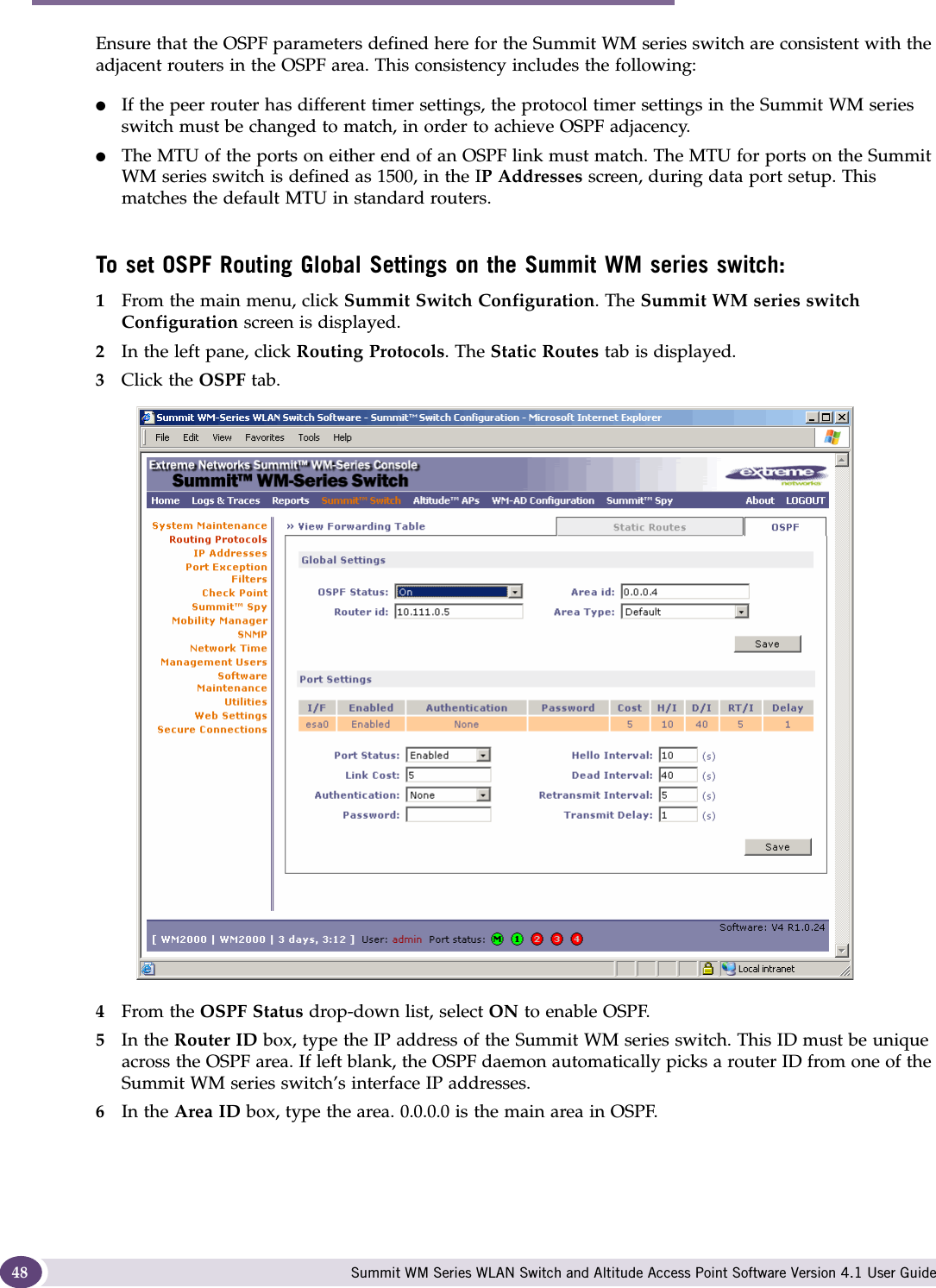
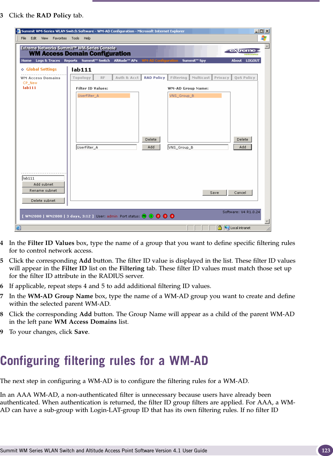
![Configuring the Summit WM series switch Summit WM Series WLAN Switch and Altitude Access Point Software Version 4.1 User Guide386Click Login. The Summit Wireless Assistant main menu screen is displayed. NOTEIn the footer of the Summit Wireless Assistant, the following is displayed:■[host name | product name | up time]If there is no key (unlicensed), the product name will not be displayed.■User is the user id you used to login in. For example, admin.■Port Status is the connectivity state of the port. M is for the Management interface, which is on eth0 and the numbered lights reflect the esa ports on the system. Green indicates the interface is up and running. Red indicates the interface is down.7From the main menu, click Summit Switch Configuration. The Summit WM series switch Configuration screen is displayed.](https://usermanual.wiki/Extreme-Networks/A3502A.user-manual-1/User-Guide-845207-Page-38.png)
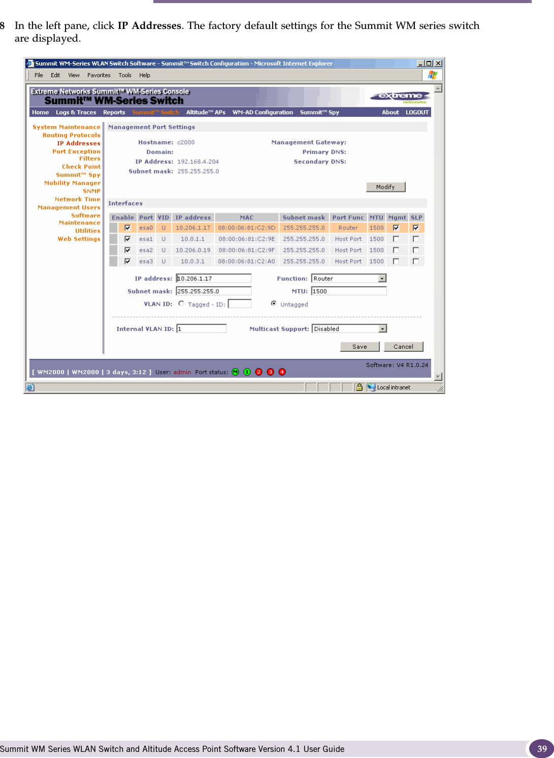
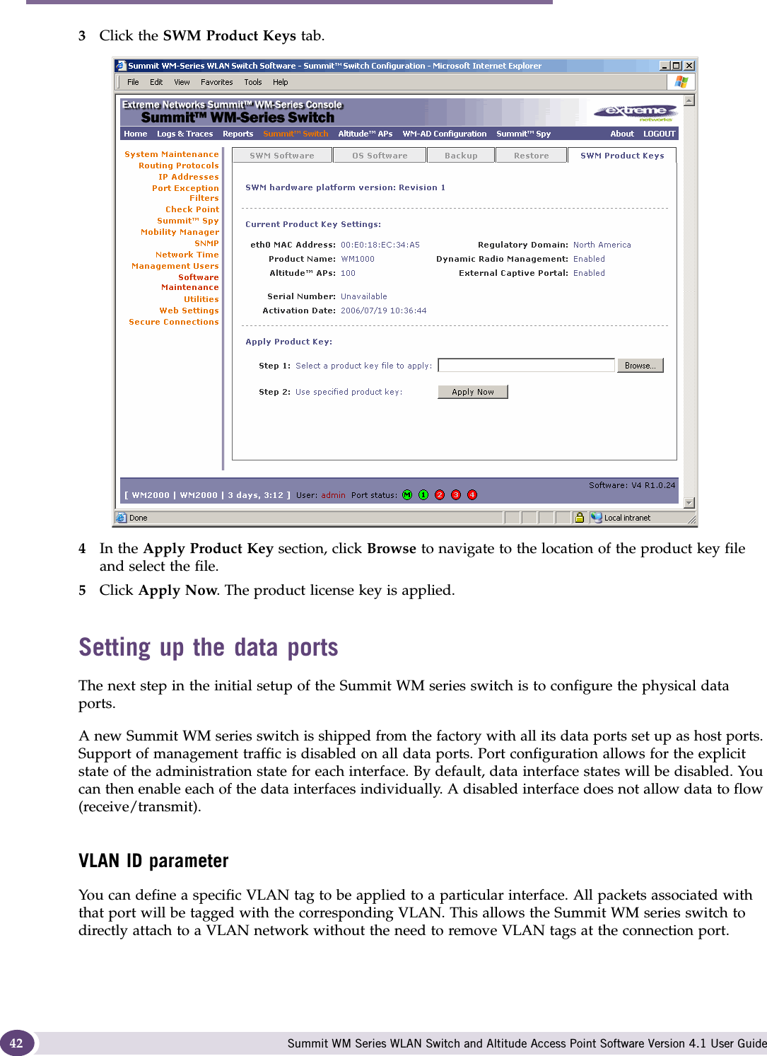
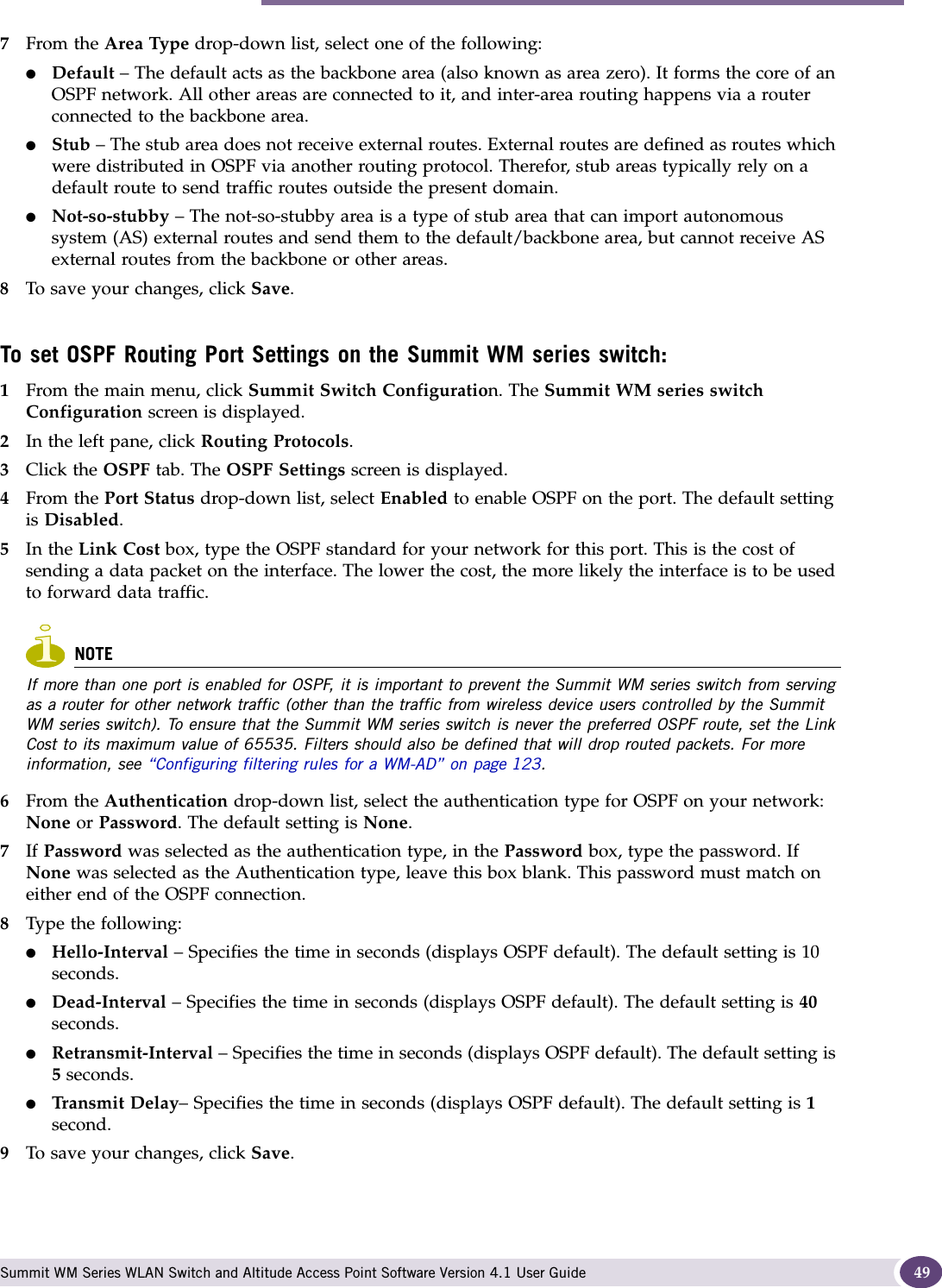
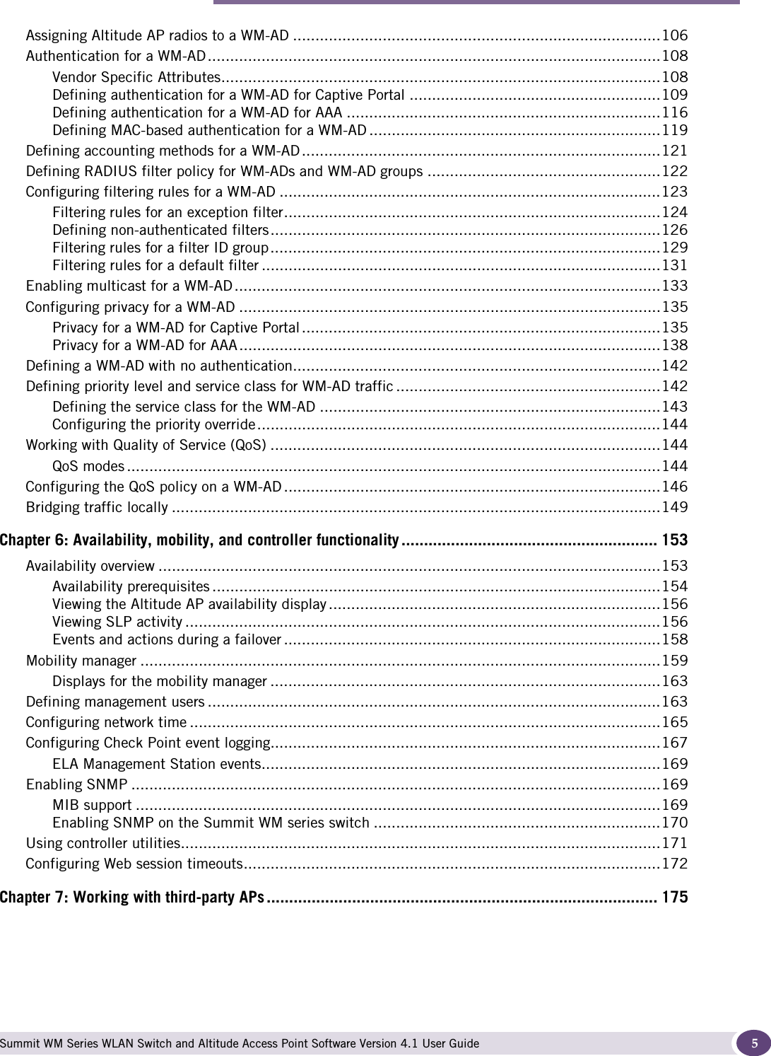
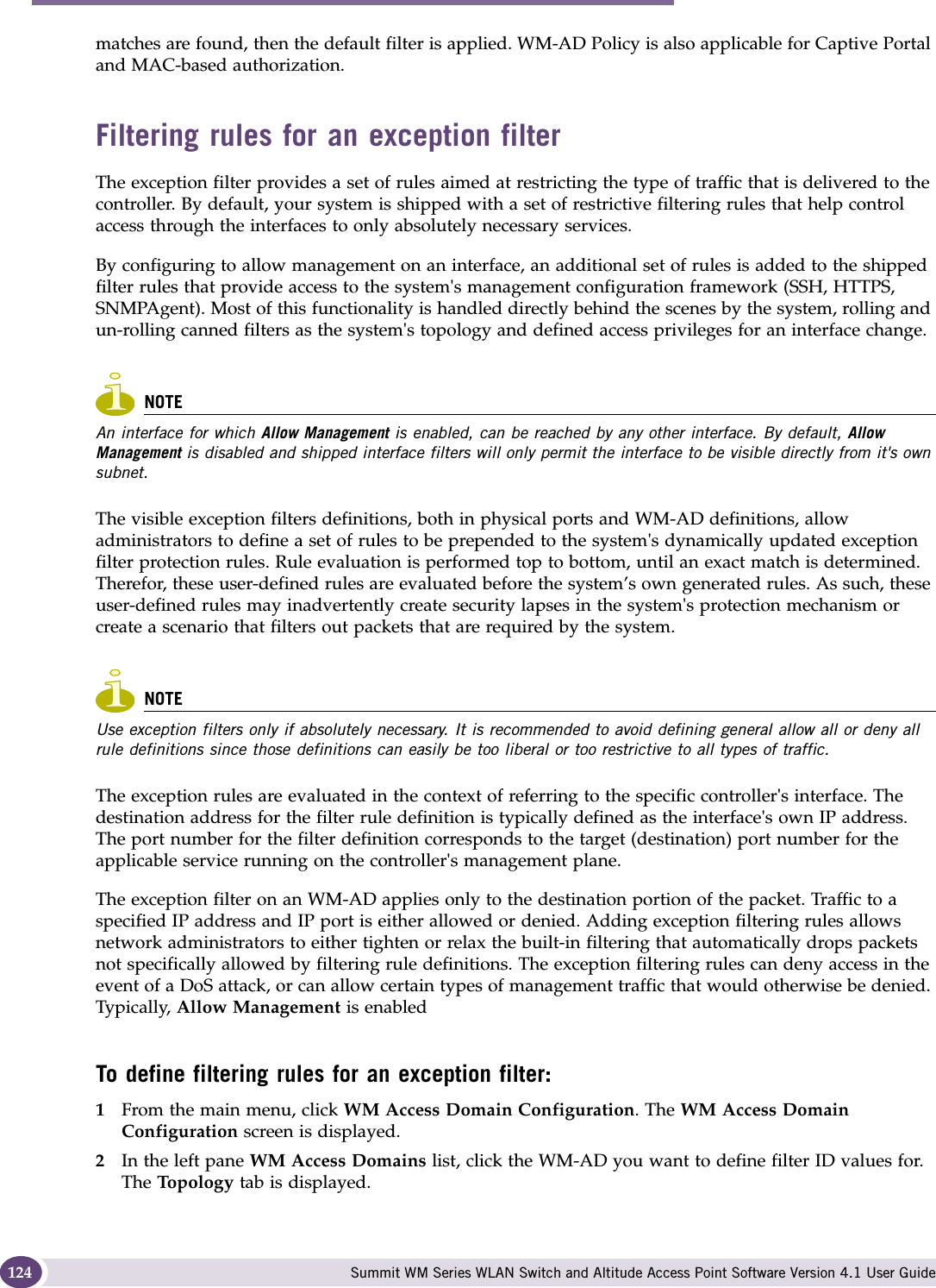
![Performing the first-time setup of the Summit WM series switch Summit WM Series WLAN Switch and Altitude Access Point Software Version 4.1 User Guide 51Enabling management traffic on an interface adds additional rules to the exception filter, which opens up the well-known IP(TCP/UDP) ports, corresponding to the HTTPS, SSH, and SNMP applications.The port-based built-in exception filtering rules, in the case of traffic from WM-AD users, are applicable to traffic targeted directly for the WM-AD interface. For example, a WM-AD filter may be generic enough to allow traffic access to the Summit WM series switch's management (for example, Allow All [*.*.*.*]). Exception filter rules are evaluated after the user's WM-AD assigned filter policy, as such, it is possible that the WM-AD policy allow the access to management functions that the exception filter denies. These packets are dropped. To enable SSH, HTTPS, or SNMP access through a data interface:1From the main menu, click Summit Switch Configuration. The Summit WM series switch Configuration screen is displayed.2In the left pane, click IP Addresses. The Management Port Settings screen is displayed.3Select the appropriate interface in the IP Addresses screen.4Select the corresponding Management checkbox.5To save your changes, click Save. User defined port-based exception filtersYou can add specific filtering rules at the port level in addition to the built-in rules. Such rules give you the capability of restricting access to a port, for specific reasons, such as a Denial of Service (DoS) attack.](https://usermanual.wiki/Extreme-Networks/A3502A.user-manual-1/User-Guide-845207-Page-51.png)

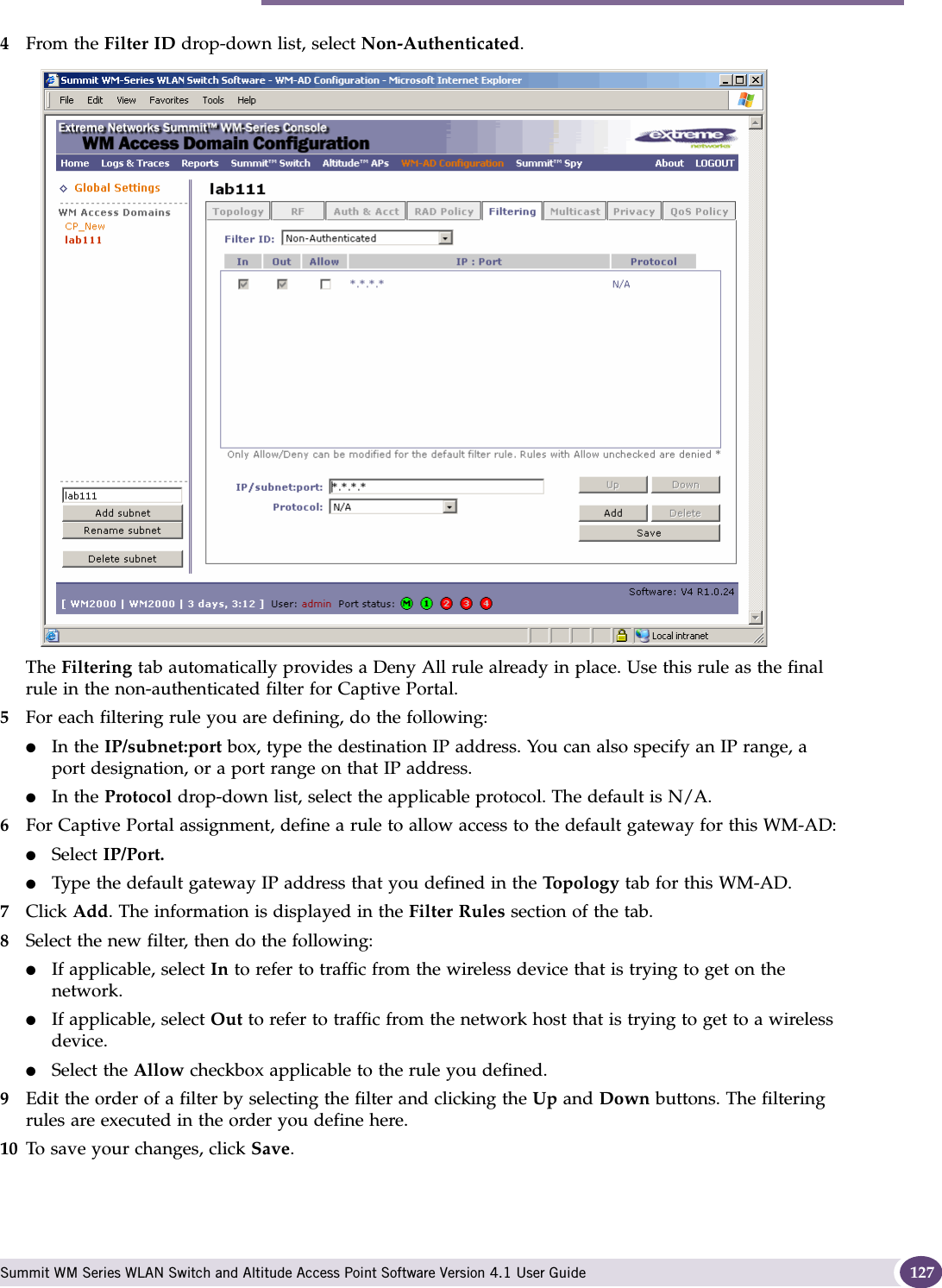
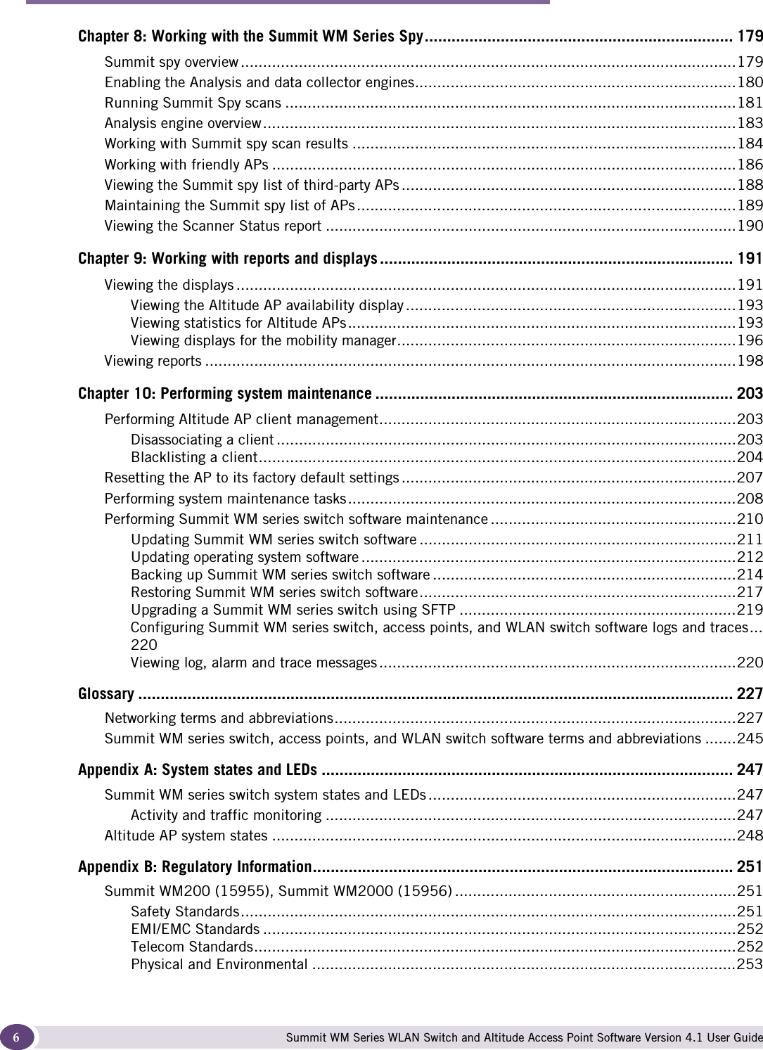
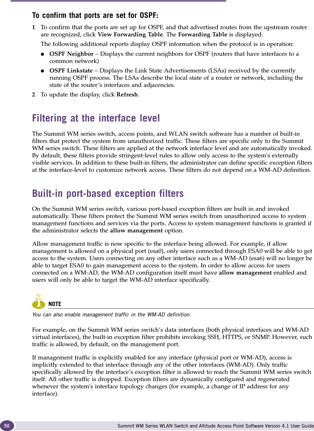
![WM Access Domain Services configuration Summit WM Series WLAN Switch and Altitude Access Point Software Version 4.1 User Guide128NOTEAdministrators must ensure that the non-authenticated filter allows access to the corresponding authentication server:●Internal Captive Portal – IP address of the WM-AD interface●External Captive Portal – IP address of external Captive Portal serverNon-authenticated filter examplesA basic non-authenticated filter for internal Captive Portal should have three rules, in the following order:NOTEFor external Captive Portal, an additional rule to Allow (in/out) access to the external Captive Portal authentication/Web server is required.If you place URLs in the header and footer of the Captive Portal page, you must explicitly allow access to any URLs mentioned in the authentication's server page, such as:●Internal Captive Portal – URLs referenced in a header or footer●External Captive Portal – URLs mentioned in the page definitionHere is another example of a non-authenticated filter that adds two more filtering rules. The two additional rules do the following: ●Deny access to a specific IP address.●Allows only HTTP traffic.Table 5: Non-authenticated filter example AIn Out Allow IP / Port Descriptionx x x IP address of default gateway (WM-AD Interface IP)Allow all incoming wireless devices access to the default gateway of the WM-AD.x x x IP address of the DNS Server Allow all incoming wireless devices access to the DNS server of the WM-AD.x x *.*.*.* Deny everything else.Table 6: Non-authenticated filter example BIn Out Allow IP / Port Descriptionx x x IP address of the default gatewayAllow all incoming wireless devices access to the default gateway of the WM-AD.x x x IP address of the DNS Server Allow all incoming wireless devices access to the DNS server of the WM-AD.x x [a specific IP address, or address plus range]Deny all traffic to a specific IP address, or to a specific IP address range (such as:0/24).x x *.*.*.*:80 Deny all port 80 (HTTP) traffic.x x *.*.*.* Deny everything else.](https://usermanual.wiki/Extreme-Networks/A3502A.user-manual-1/User-Guide-845207-Page-128.png)
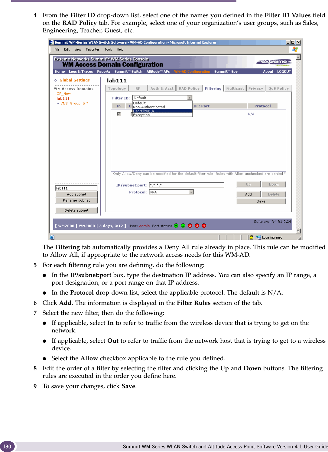
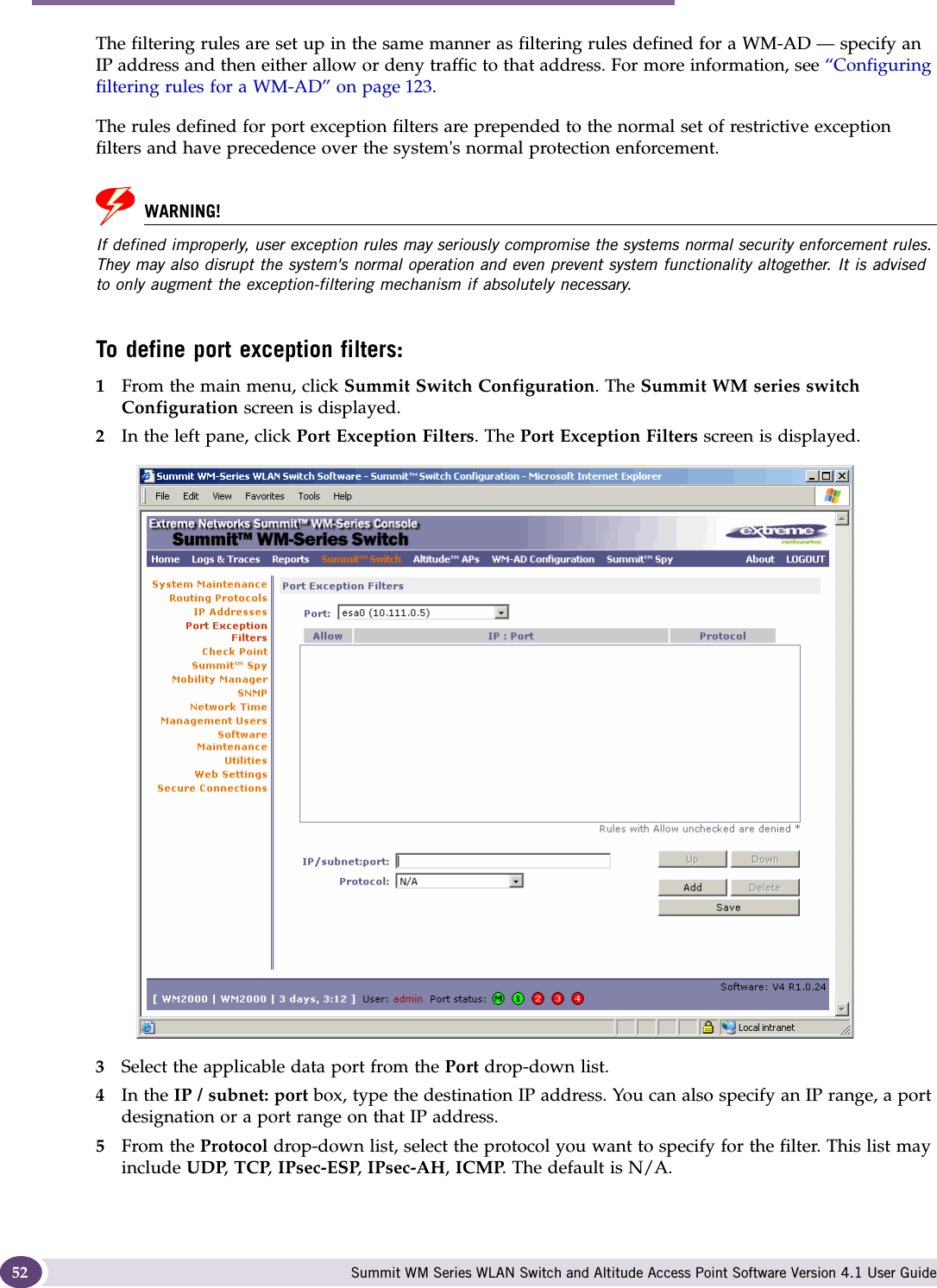
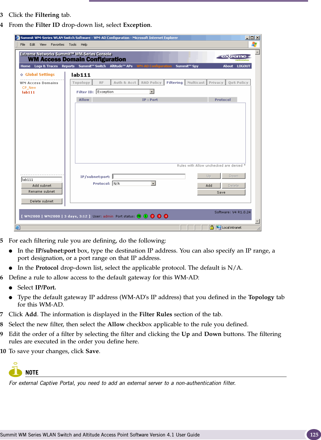
![Configuring filtering rules for a WM-AD Summit WM Series WLAN Switch and Altitude Access Point Software Version 4.1 User Guide 131Filtering rules by filter ID examplesBelow are two examples of possible filtering rules for a filter ID. The first example disallows some specific access before allowing everything else.The second example does the opposite of the first example. It allows some specific access and denies everything else. Filtering rules for a default filterAfter authentication of the wireless device user, the default filter will apply only after:●No match is found for the Exception filter rules.●No filter ID attribute value is returned by the authentication server for this user.●No match is found on the Summit WM series switch for a filter ID value.The final rule in the default filter should be a catch-all rule for any traffic that did not match a filter. A final Allow All rule in a default filter will ensure that a packet is not dropped entirely if no other match can be found. WM-AD Policy is also applicable for Captive Portal and MAC-based authorization.To define the filtering rules for a default filter:1From the main menu, click WM Access Domain Configuration. The WM Access Domain Configuration screen is displayed.2In the left pane WM Access Domains list, click the WM-AD you want to define the filtering rules for a default filter. The To pol ogy tab is displayed.3Click the Filtering tab.Table 7: Filtering rules by filter ID example AIn Out Allow IP / Port Descriptionx x *.*.*.*:22-23 SSH and telnet sessionsx x [specific IP address, range] Deny all traffic to a specific IP address or address rangex x x *.*.*.*. Allow everything elseTable 8: Filtering rules by filter ID example BIn Out Allow IP / Port Descriptionx x x [specific IP address, range] Allow traffic to a specific IP address or address range.x x *.*.*.*. Deny everything else.](https://usermanual.wiki/Extreme-Networks/A3502A.user-manual-1/User-Guide-845207-Page-131.png)
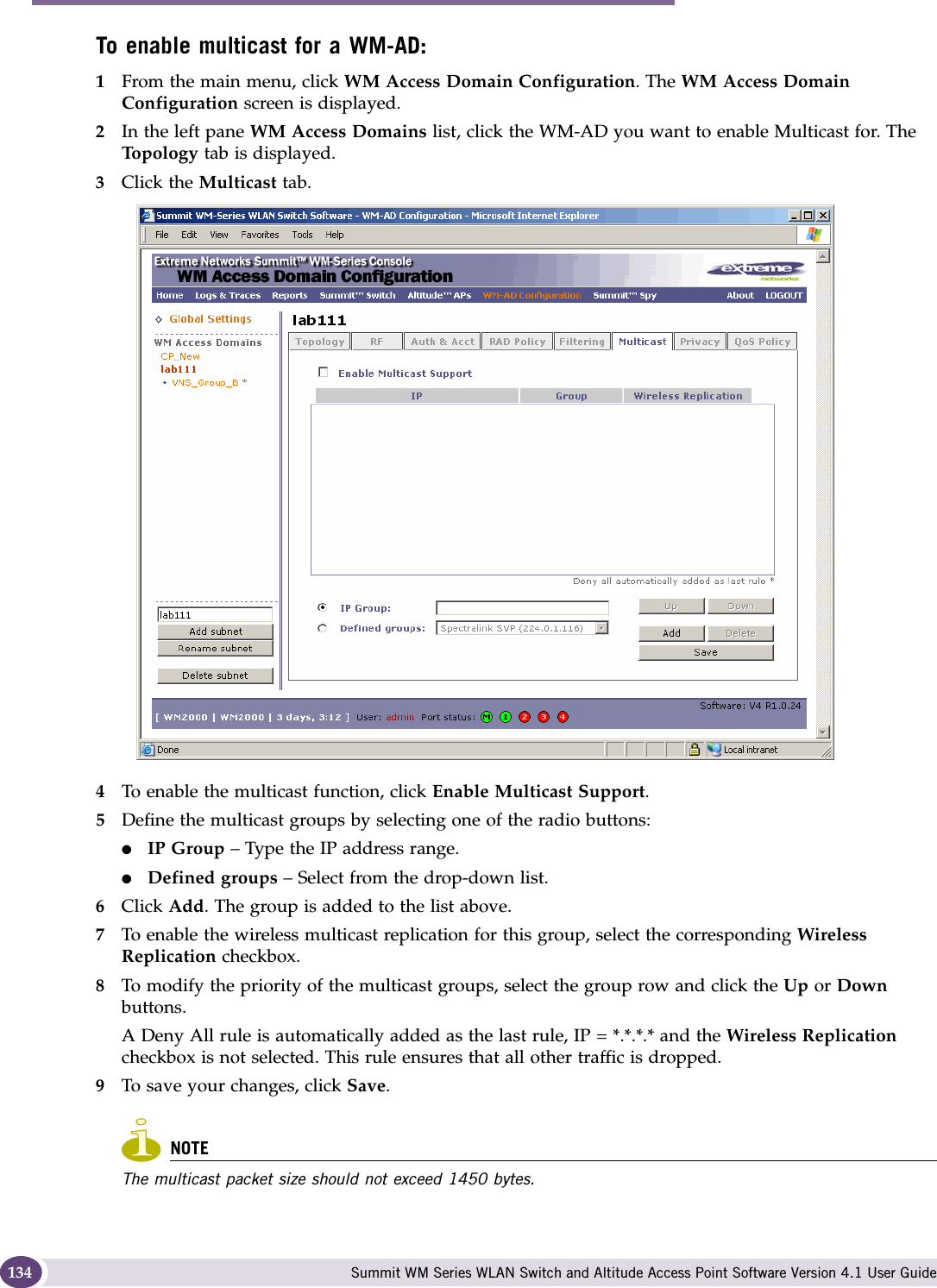
![Enabling multicast for a WM-AD Summit WM Series WLAN Switch and Altitude Access Point Software Version 4.1 User Guide 133Filtering rules for an AAA child group WM-ADIf you defined a child group for an AAA WM-AD, it will have the same authentication parameters and filter IDs as the parent WM-AD. However, you can define different filtering rules for the filters IDs in the child configuration from those in the parent configuration.Filtering rules between two wireless devicesTraffic from two wireless devices that are on the same WM-AD and are connected to the same Altitude AP will pass through the Summit WM series switch and therefore be subject to filtering policy. You can set up filtering rules that allow each wireless device access to the default gateway, but also prevent each device from communicating with each other. Add the following two rules to a filter ID filter, before allowing everything else:Enabling multicast for a WM-ADA mechanism that supports multicast traffic can be enabled as part of a WM-AD definition. This mechanism is provided to support the demands of VoIP and IPTV network traffic, while still providing the network access control.Define a list of multicast groups whose traffic is allowed to be forwarded to and from the WM-AD. The default behavior is to drop the packets. For each group defined, you can enable Multicast Replication by group.NOTEBefore enabling multicast filters and depending on the topology of the WM-AD, you may need to define which physical interface to use for multicast relay. Define the multicast port on the IP Addresses screen. For more information, see “Setting up the data ports” on page 42.x x Intranet IP 10.3.0.20 Allow all other traffic from the wireless devices to the Intranet networkx x Intranet IP 10.3.0.20 Allow all other traffic from Intranet network to wireless devicesx x x *.*.*.*. Allow everything elseTable 11: Rules between two wireless devicesIn Out Allow IP / Port Descriptionx x x [Intranet IP] Allow access to the Gateway IP address of the WM-AD onlyx x [Intranet IP, range] Deny all access to the WM-AD subnet range (such as 0/24)x x x *.*.*.*. Allow everything elseTable 10: Default filter example B (Continued)In Out Allow IP / Port Description](https://usermanual.wiki/Extreme-Networks/A3502A.user-manual-1/User-Guide-845207-Page-133.png)