Extreme Networks A3502A ALTITUDE 350-2 ACCESS POINT User Manual SummitWM UG BK71806 1
Extreme Networks ALTITUDE 350-2 ACCESS POINT SummitWM UG BK71806 1
UserManual.wiki
>
Extreme Networks
>
A3502A User Manual
>
USERS MANUAL
Contents
1.
USERS MANUAL
2.
user manual 1
3.
user manual 2
USERS MANUAL
Navigation menu
Upload a User Manual
Namespaces
Wiki Guide
HTML
PDF
Info
Views
User Manual
Discussion / Help
Navigation

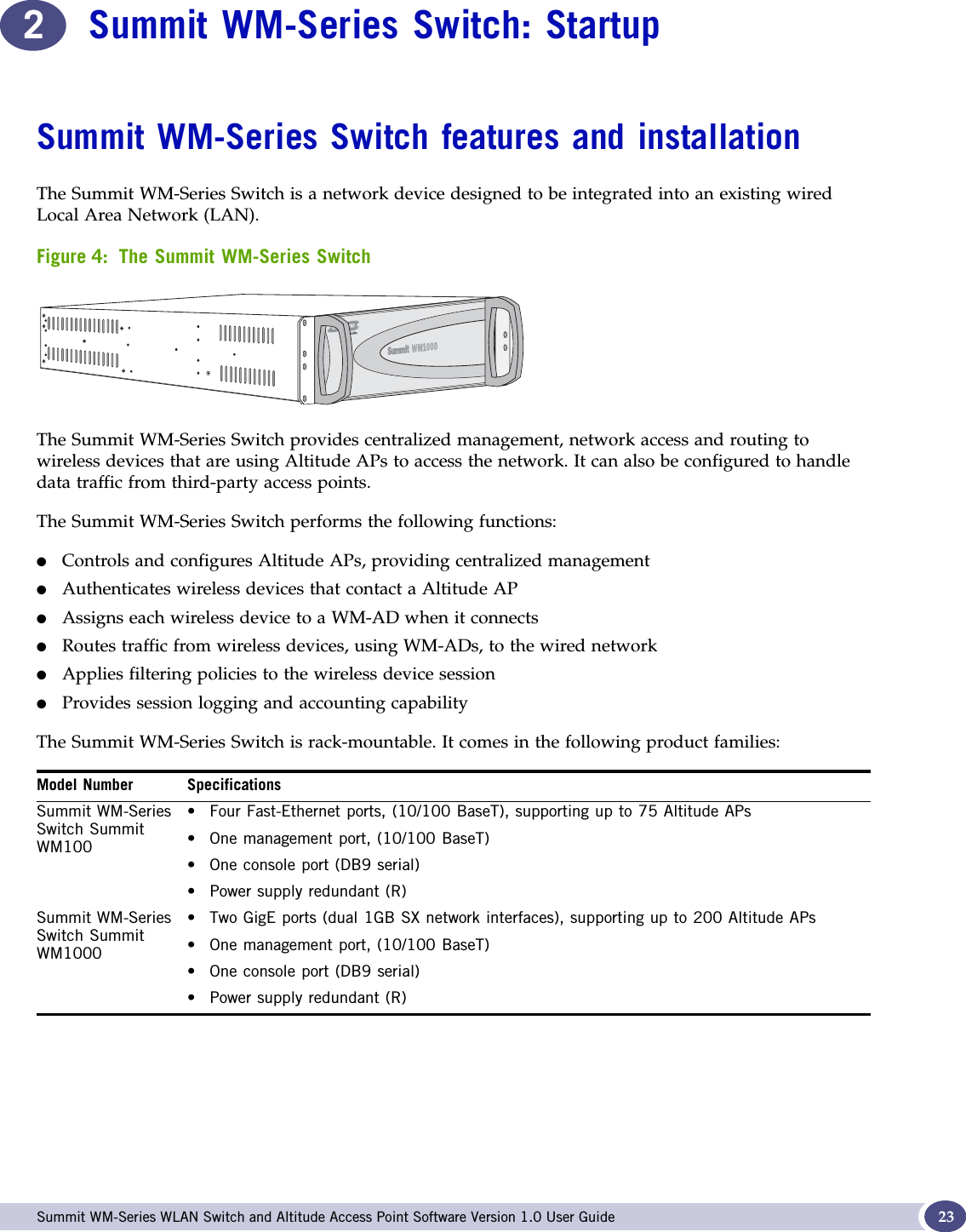
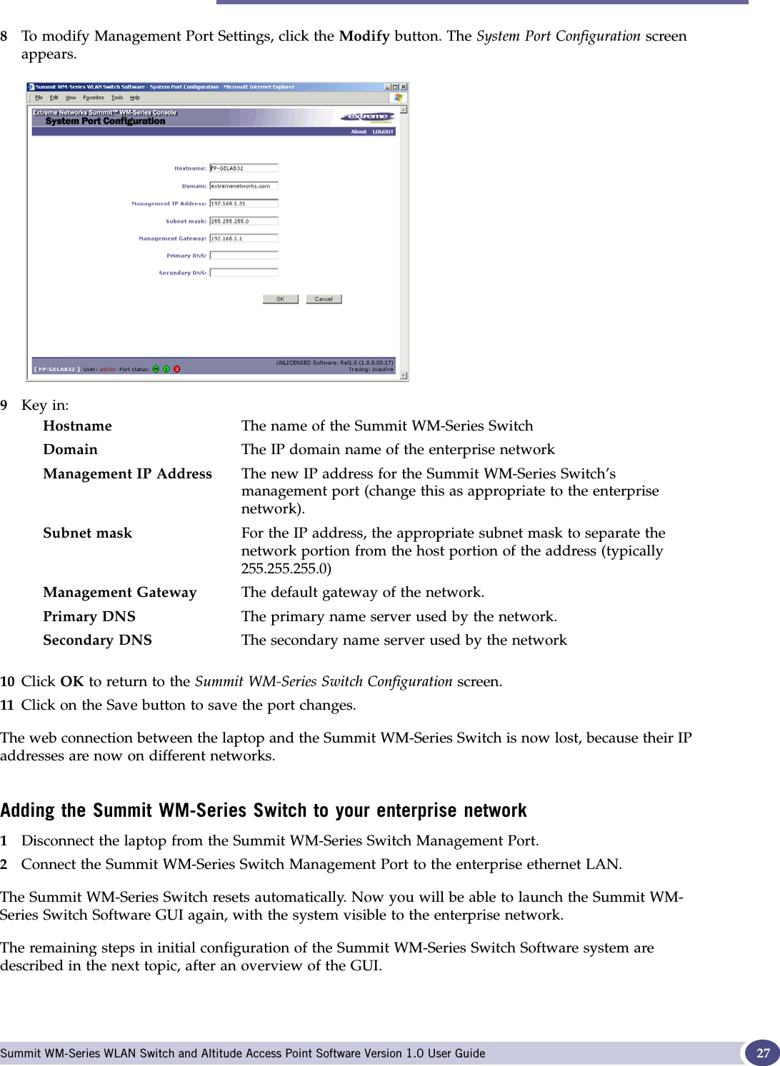
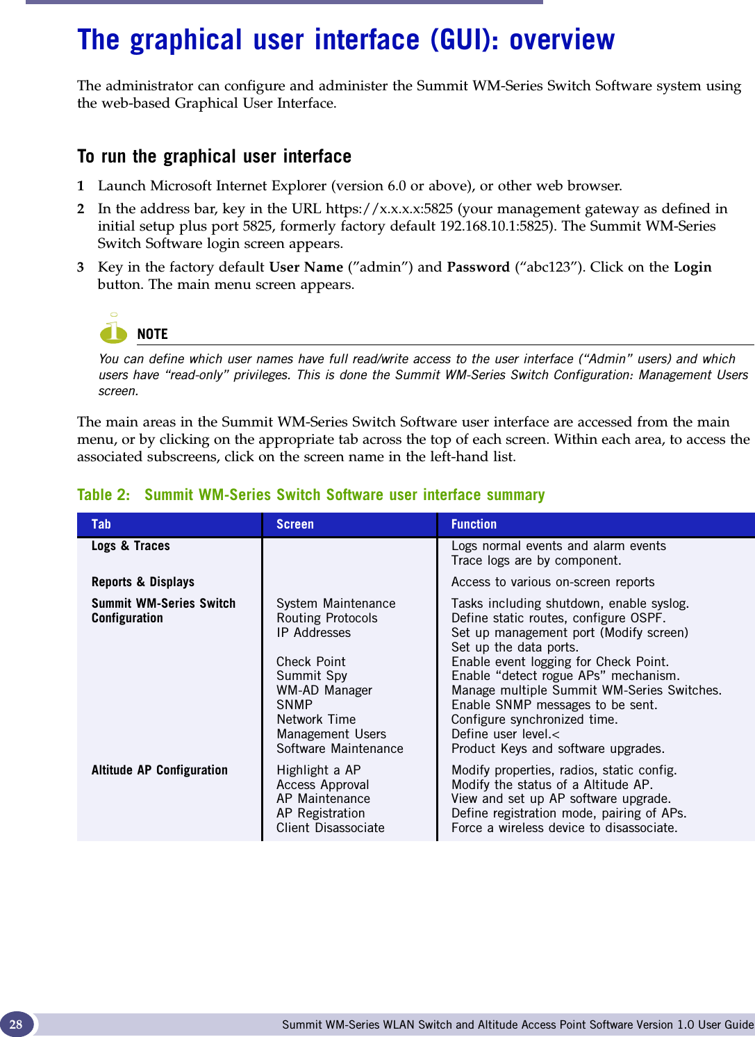
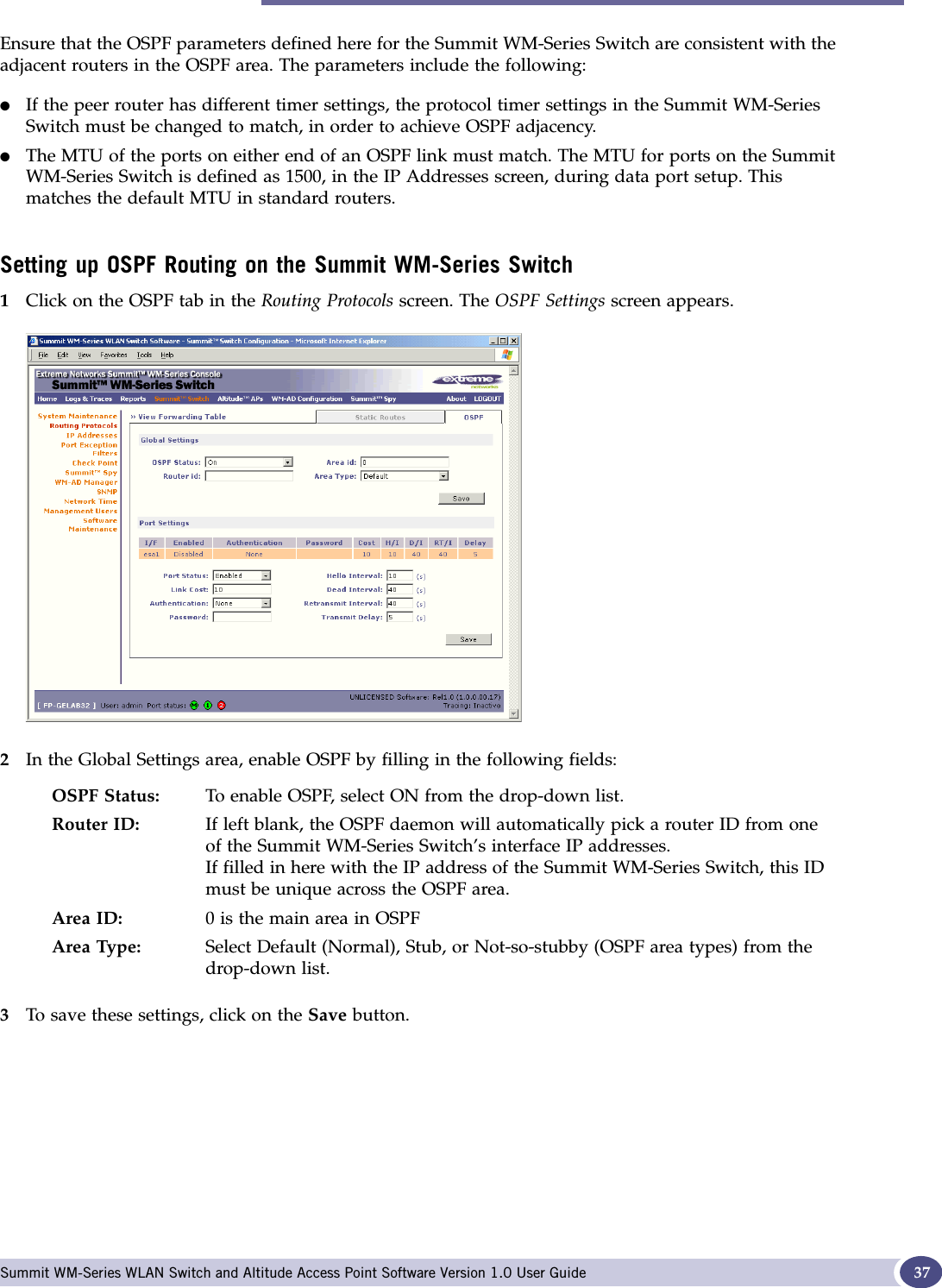
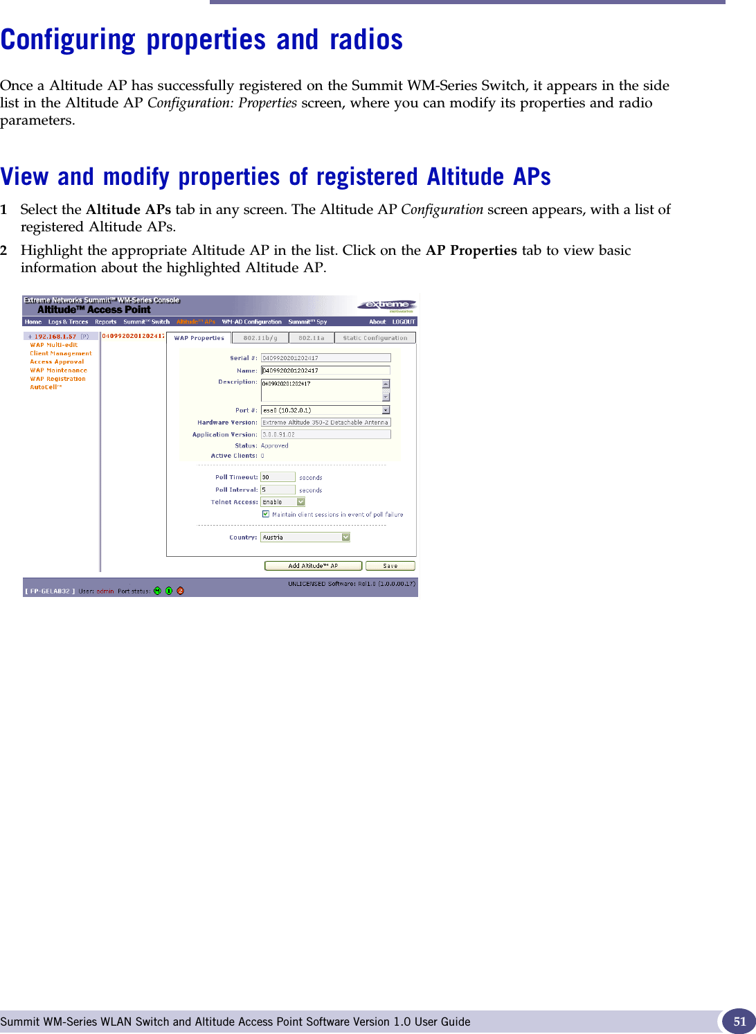
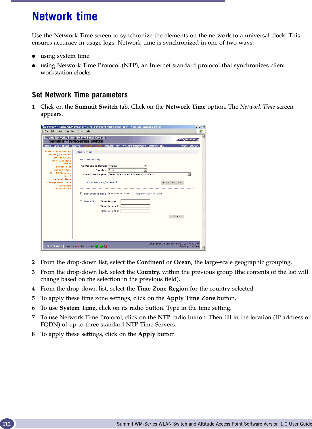
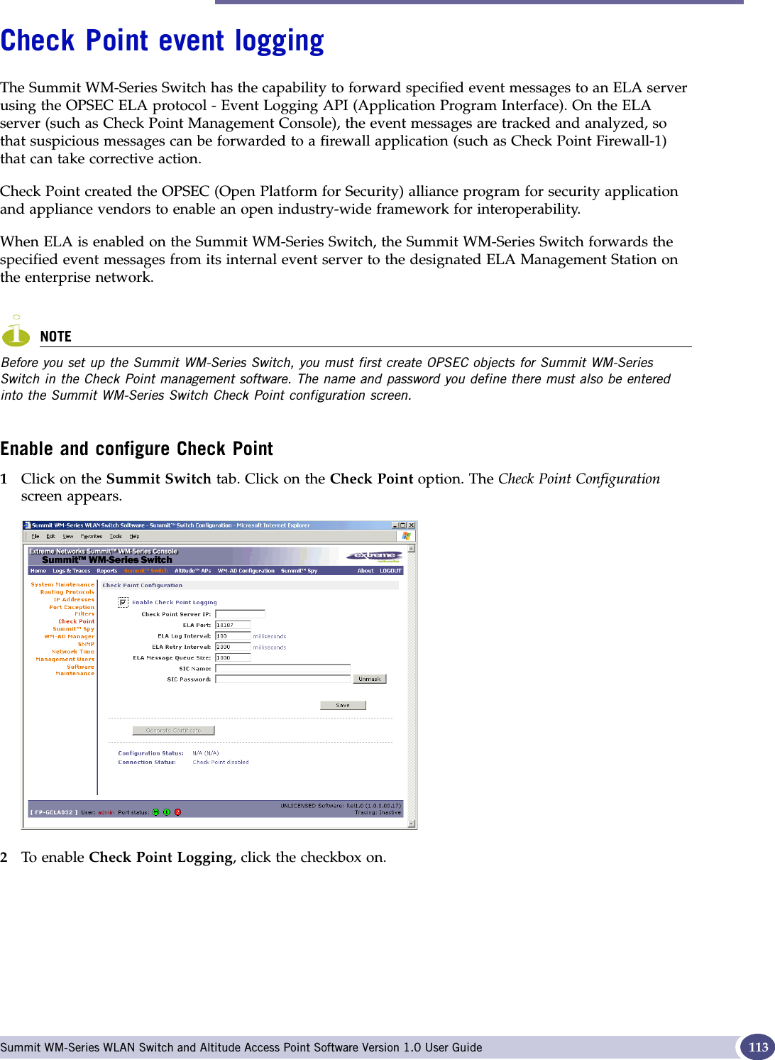
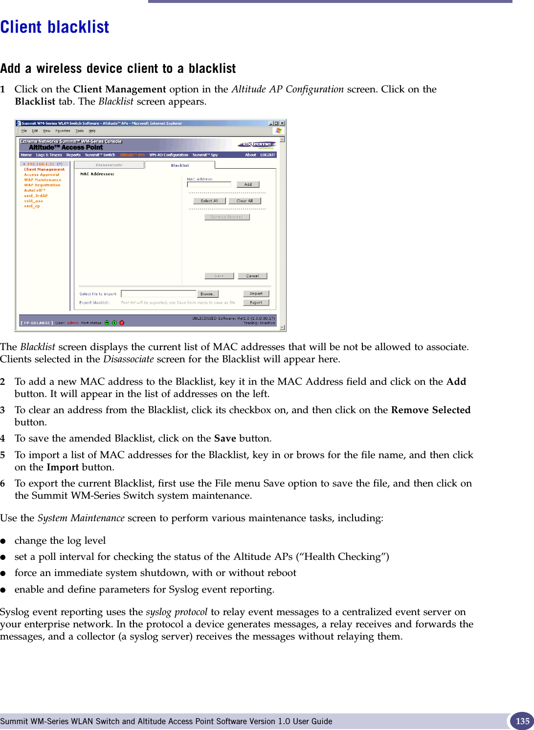
![About this Guide Summit WM-Series WLAN Switch and Altitude Access Point Software Version 1.0 User Guide10●Appendix C provides background information on how the discovery process uses these network services.●Appendix D provides a reference list of RFCs supported.●Appendix E provides information on a support tool.●Appendix F provides a reference list of the RADIUS Attributes that are supported by the Summit WM-Series Switch Software.●Appendix G provides a reference list of the log and event messages.●Appendix H provides regulatory information for the 6XPPLW:06HULHV6ZLWFKDQGWKH$OWLWXGH:LUHOHVV$FFHVV3RLQWThis guide also contains a glossary of standard industry terms used in this guide.Formatting conventionsThe Summit WM-Series Switch Software documentation uses the following formatting conventions to make it easier to find information and follow procedures:●Bold text is used to identify components of the management interface, such as menu items and section of pages, as well as the names of buttons and text boxes.For example: Click Logout.●Monospace font is used in code examples and to indicate text that you type.For example: Type https://<hls-address>[:mgmt-port>]●The following symbols are used to draw your attention to additional information:NOTENotes identify useful information that is not essential, such as reminders, tips, or other ways to perform a task.WARNING!Warnings identify essential information. Ignoring a warning can lead to problems with the application.Documentation feedbackIf you have any problems using this document, please contact your next level of support:●Customers should contact the Extreme Networks Technical Assistance Center (TAC).When you call, please have the following information ready. This will help us to identify the document that you are referring to.●Title: Summit WM-Series WLAN Switch and Altitude Access Point Software Version 1.0 User Guide●Part Number: 100198-00 Rev 01](https://usermanual.wiki/Extreme-Networks/A3502A.USERS-MANUAL/User-Guide-683282-Page-10.png)

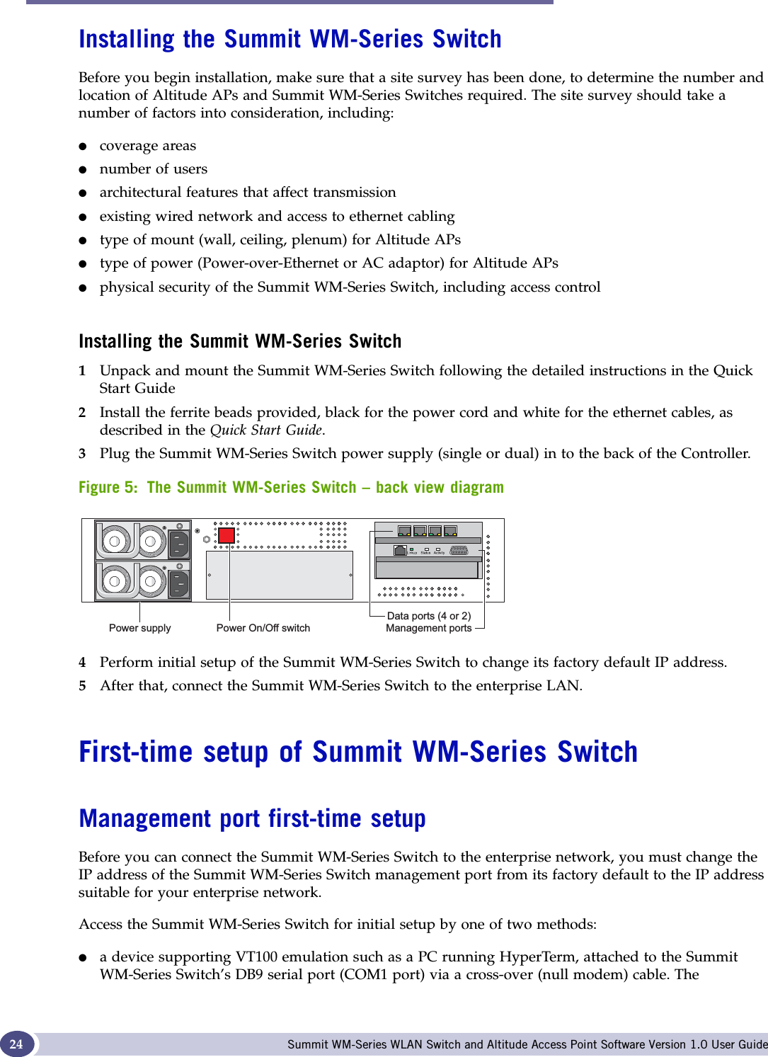

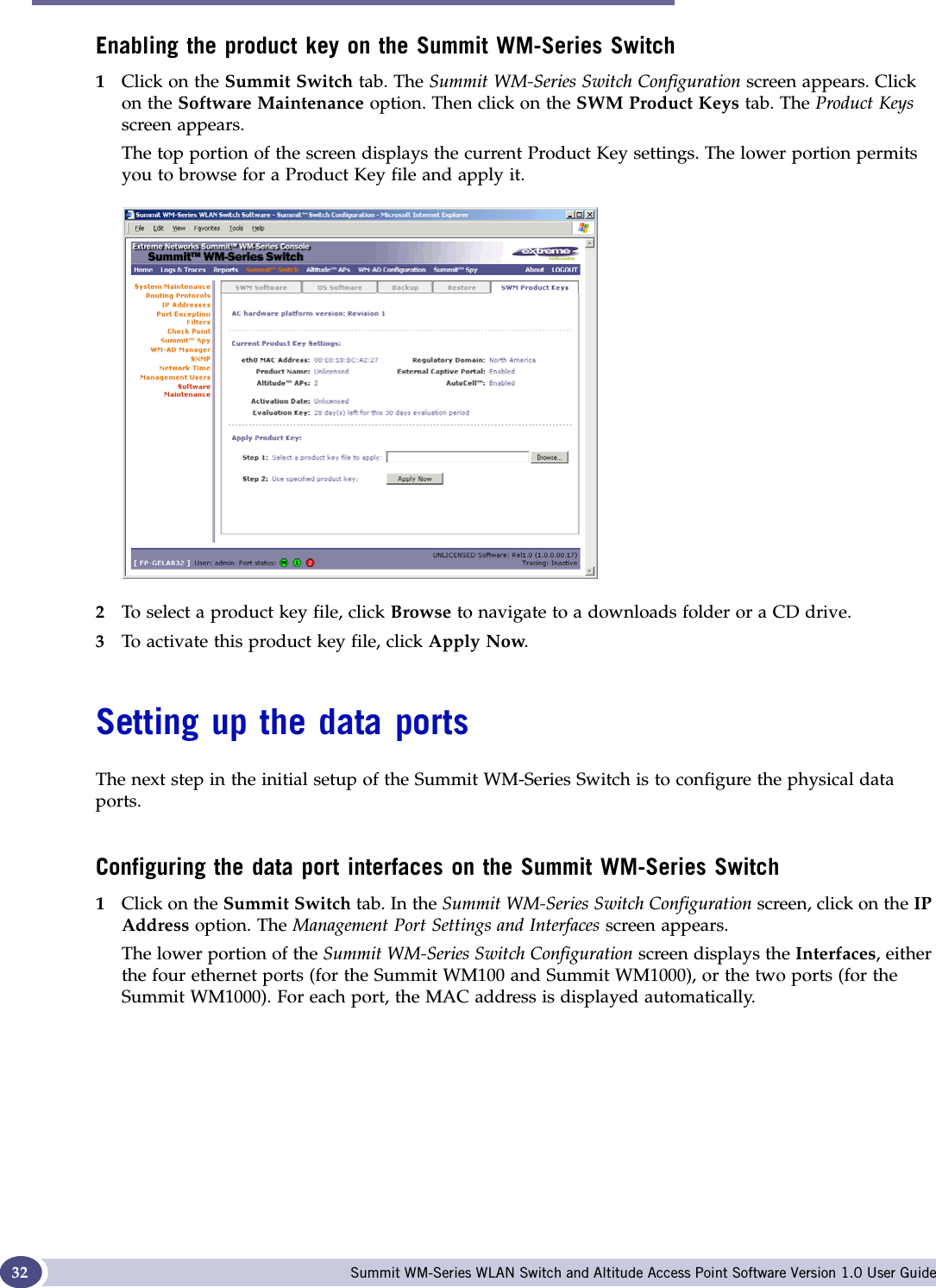
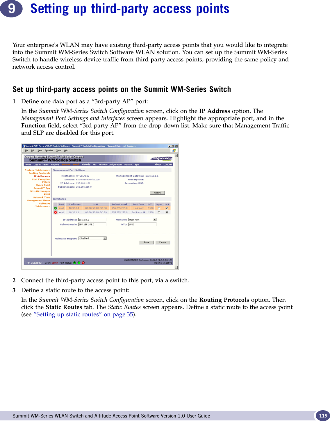
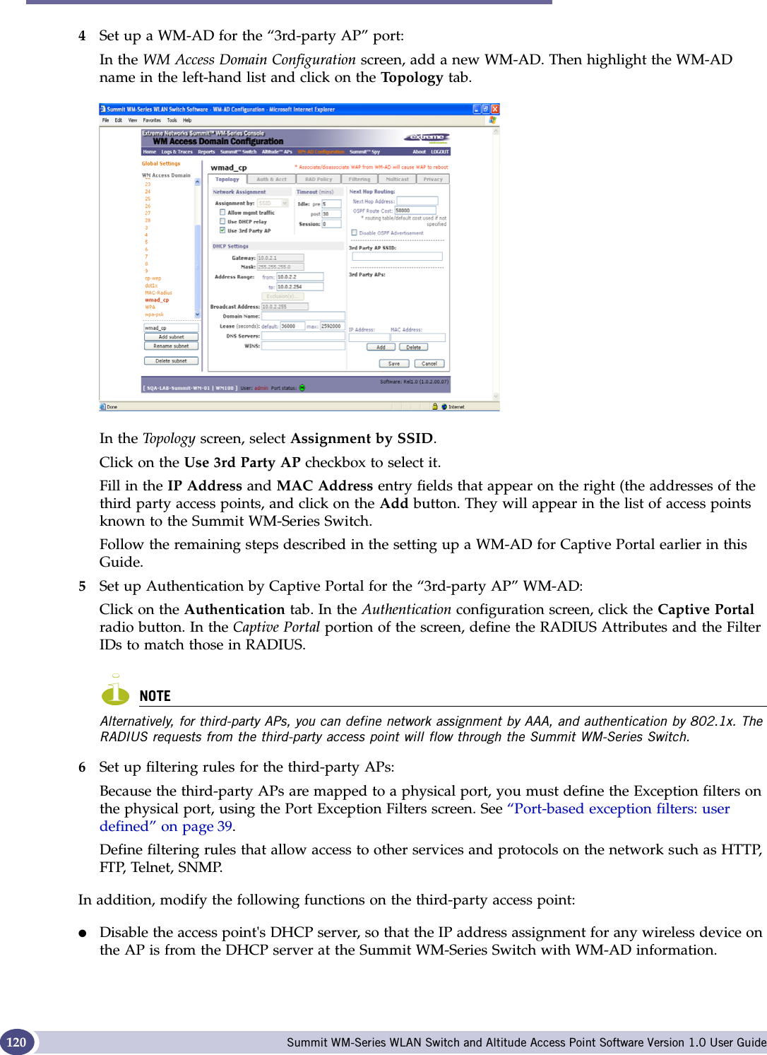
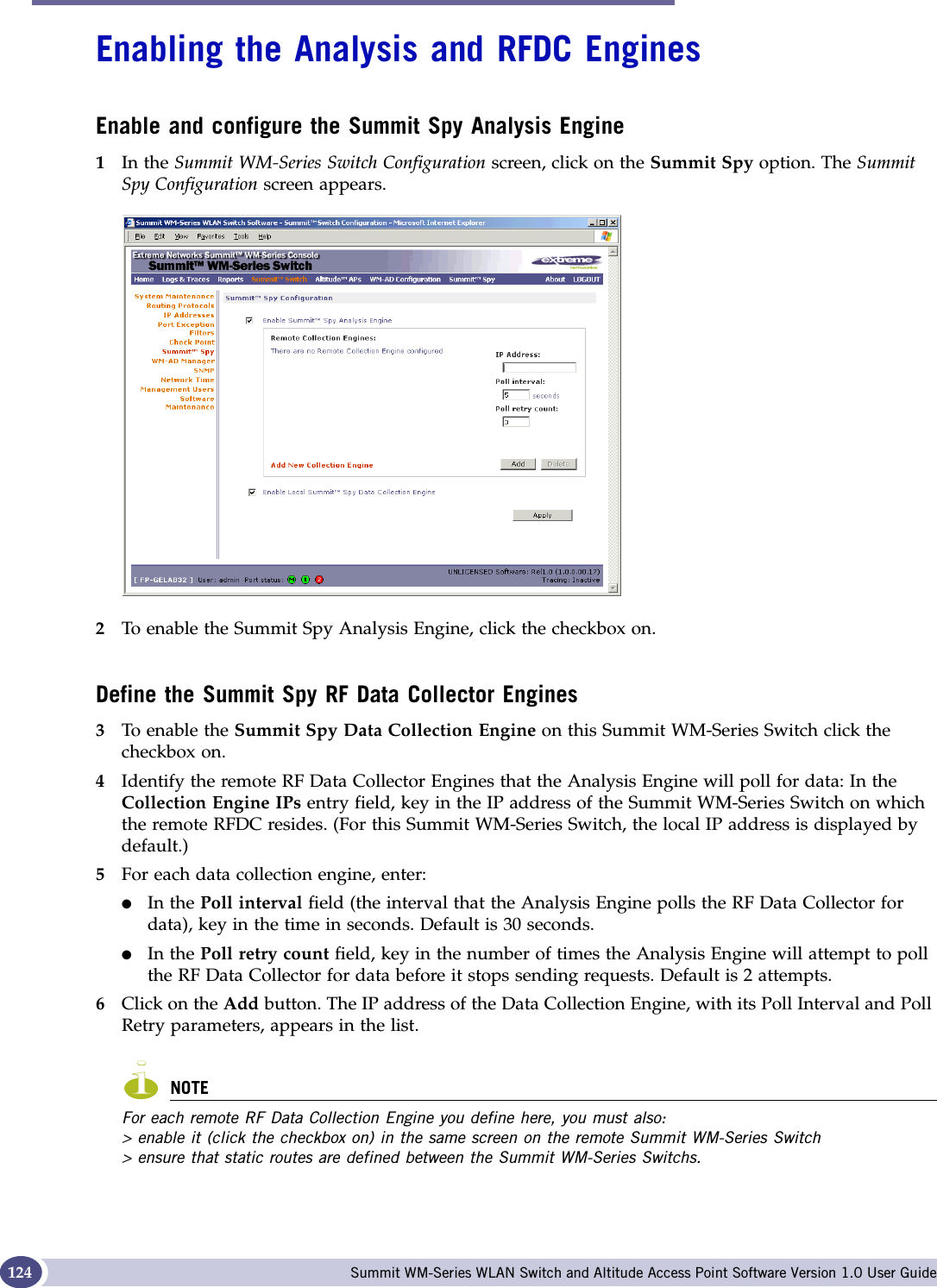
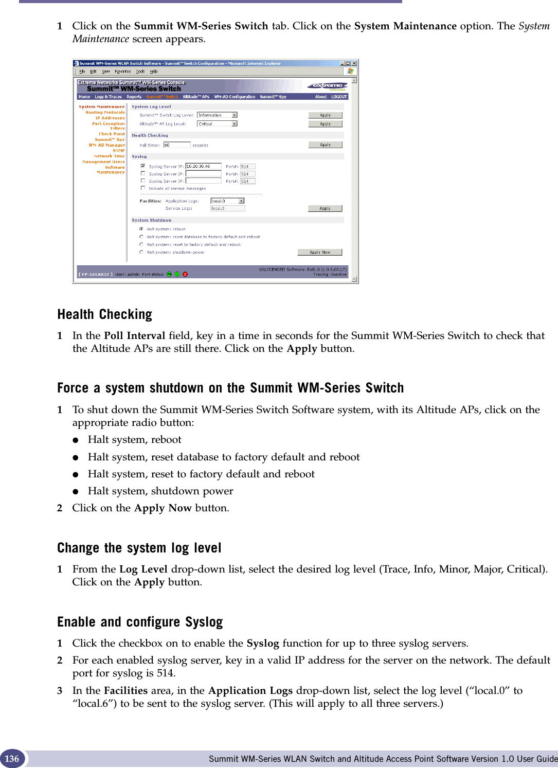
![Setting up static routes Summit WM-Series WLAN Switch and Altitude Access Point Software Version 1.0 User Guide 35Setting up static routesIt is recommended that you define a default route to your enterprise network, either with a static route or by using OSPF protocol. This will enable the Summit WM-Series Switch to forward wireless packets to the remainder of the network.Setting up a static route on the Summit WM-Series Switch1Click on the Summit Switch tab. In the Summit WM-Series Switch Configuration screen, click on the Routing Protocols option. 2Click the Static Routes tab. The Static Routes screen appears.3To add a new route, click in the Destination Address field and key in the destination IP address of a packet.[The destination network IP address that this static route applies to. Packets with this destination address will be sent to the Destination below.] To define a default static route for any unknown address not in the routing table, key in 0.0.0.0.4Key in the Subnet Mask. For the IP address, the appropriate subnet mask to separate the network portion from the host portion of the address (typically 255.255.255.0). For the default static route for any unknown address, key in 0.0.0.0.5In the Gateway field, key in the IP address of the gateway (the IP address of the specific router port or gateway on the same subnet as the Summit WM-Series Switch to which to route these packets; that is, the IP address of the next hop between the Summit WM-Series Switch and the packet’s ultimate destination).6Click on the Add button. The new route appears in the list, numbered sequentially.](https://usermanual.wiki/Extreme-Networks/A3502A.USERS-MANUAL/User-Guide-683282-Page-35.png)
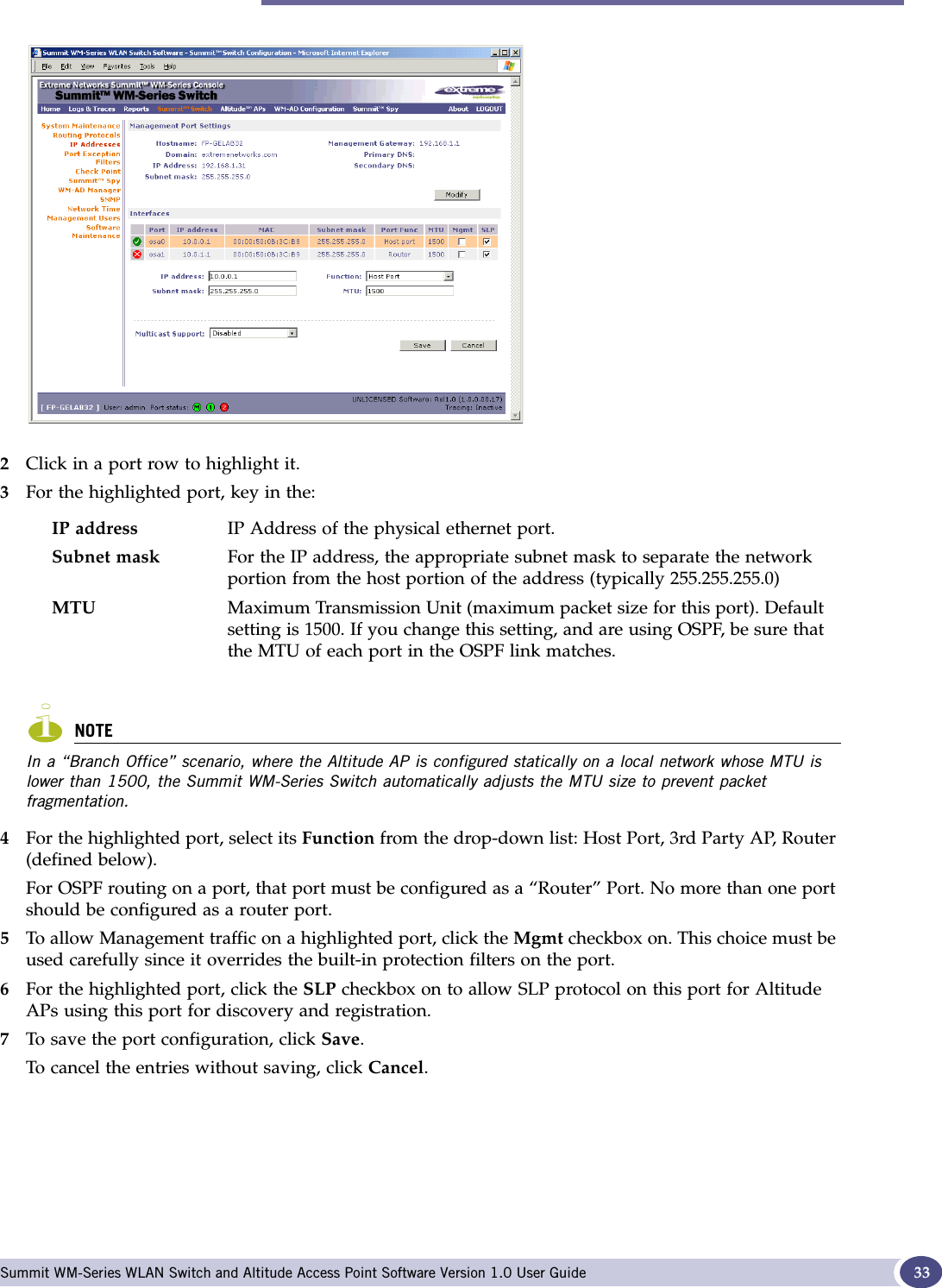
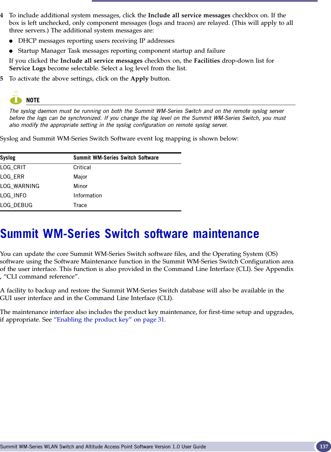
![Filtering at the interface level Summit WM-Series WLAN Switch and Altitude Access Point Software Version 1.0 User Guide 39Port-based exception filters: built-inOn the Summit WM-Series Switch, various port-based exception filters are built in and invoked automatically. These filters protect the Summit WM-Series Switch from unauthorized access to system management functions and services via the ports. For example, on the Summit WM-Series Switch’s data interfaces (both physical interfaces and WM-AD virtual interfaces), the built-in exception filter prohibits invoking SSH, HTTPS, or SNMP. However, such traffic is allowed, by default, on the Management port.To enable SSH, HTTPS, or SNMP access through a data interface, select the interface in the IP Addressesscreen and click the “Management” checkbox on. You can also enable such management traffic in the WM-AD definition.If management traffic is explicitly enabled for any interface (physical port or WM-AD), access is implicitly extended to that interface through any of the other interface. (WM-AD).Only traffic specifically allowed by the interface’s exception filter is allowed to reach the Summit WM-Series Switch itself. All other traffic is dropped. Exception filters are dynamically configured, and are regenerated whenever the system's interface topology changes (a change of IP address for any interface). Enabling management traffic on an interface adds additional rules to the exception filter to open up the well-known IP(TCP/UDP) ports corresponding to the HTTPS, SSH and SNMP applications.The port-based built-in exception filtering rules, in the case of traffic from WM-AD users, operate only on traffic that is targeted directly to one of the WM-AD's interfaces. For example, a WM-AD filter may be generic enough to allow traffic access to the Summit WM-Series Switch's management (Allow All [*.*.*.*]). The traffic will initially be allowed according to the WM-AD user’s policy, but may then be denied by the exception filter of the WM-AD interface.Port-based exception filters: user definedYou can add specific filtering rules at the port level in addition to the built-in rules. Such rules give you the capability of restricting access to a port, for specific reasons, such as a Denial of Service (DoS) attack.To define filtering rules that are associated with one of the physical data ports on the Summit WM-Series Switch rather than with a WM-AD, use the Port Exception Filter screen. The filtering rules are set up in the same manner as filtering rules defined for a WM-AD — specify an IP address and then either “Allow” or “Deny” traffic to that address. See “Filtering rules for a WM-AD” on page 86.Exception filtering rules that you will define for a WM-AD will apply to the wireless device users after their authentication, whereas the filtering rules that you define here apply to all traffic on a physical port.](https://usermanual.wiki/Extreme-Networks/A3502A.USERS-MANUAL/User-Guide-683282-Page-39.png)
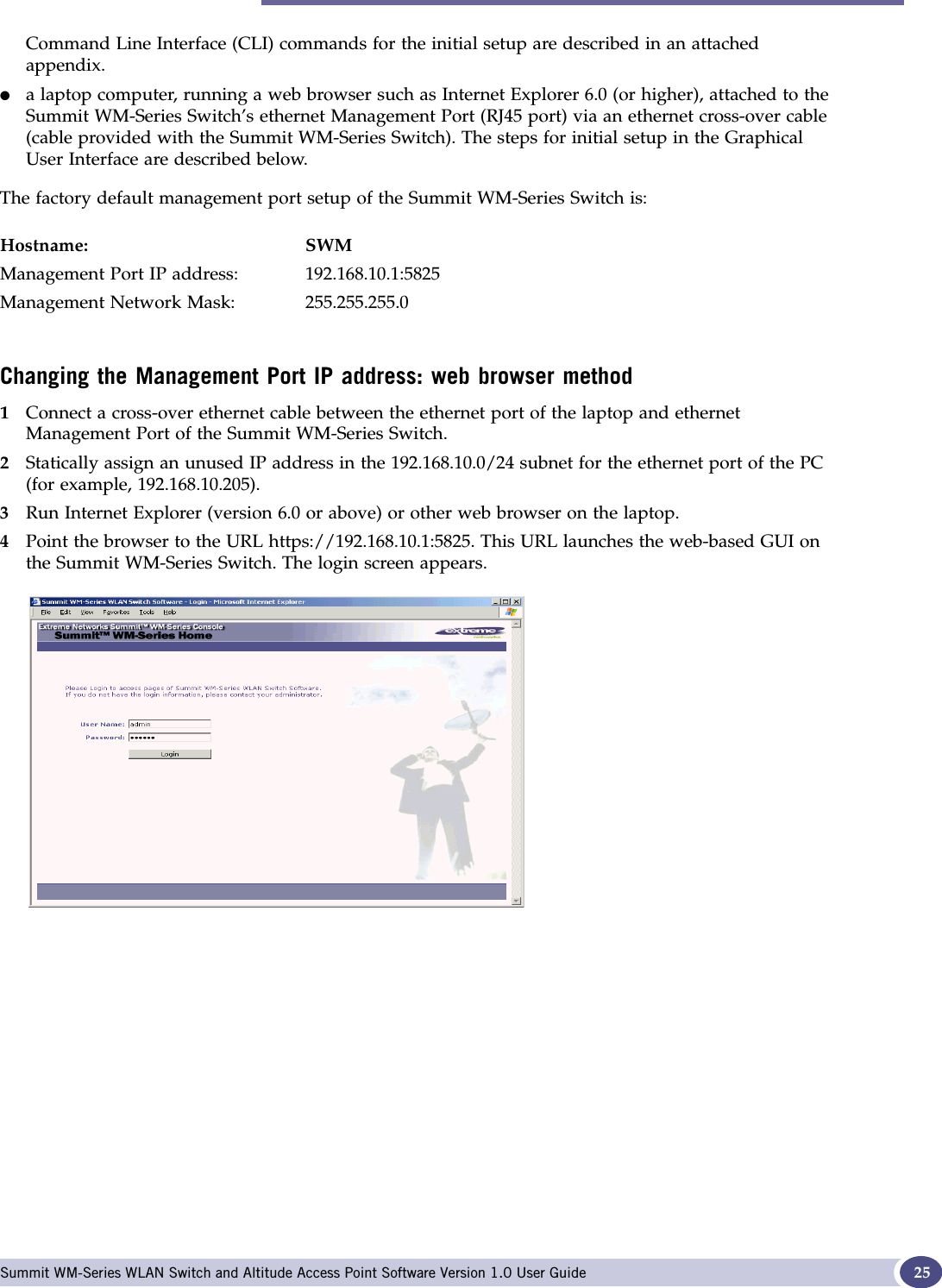
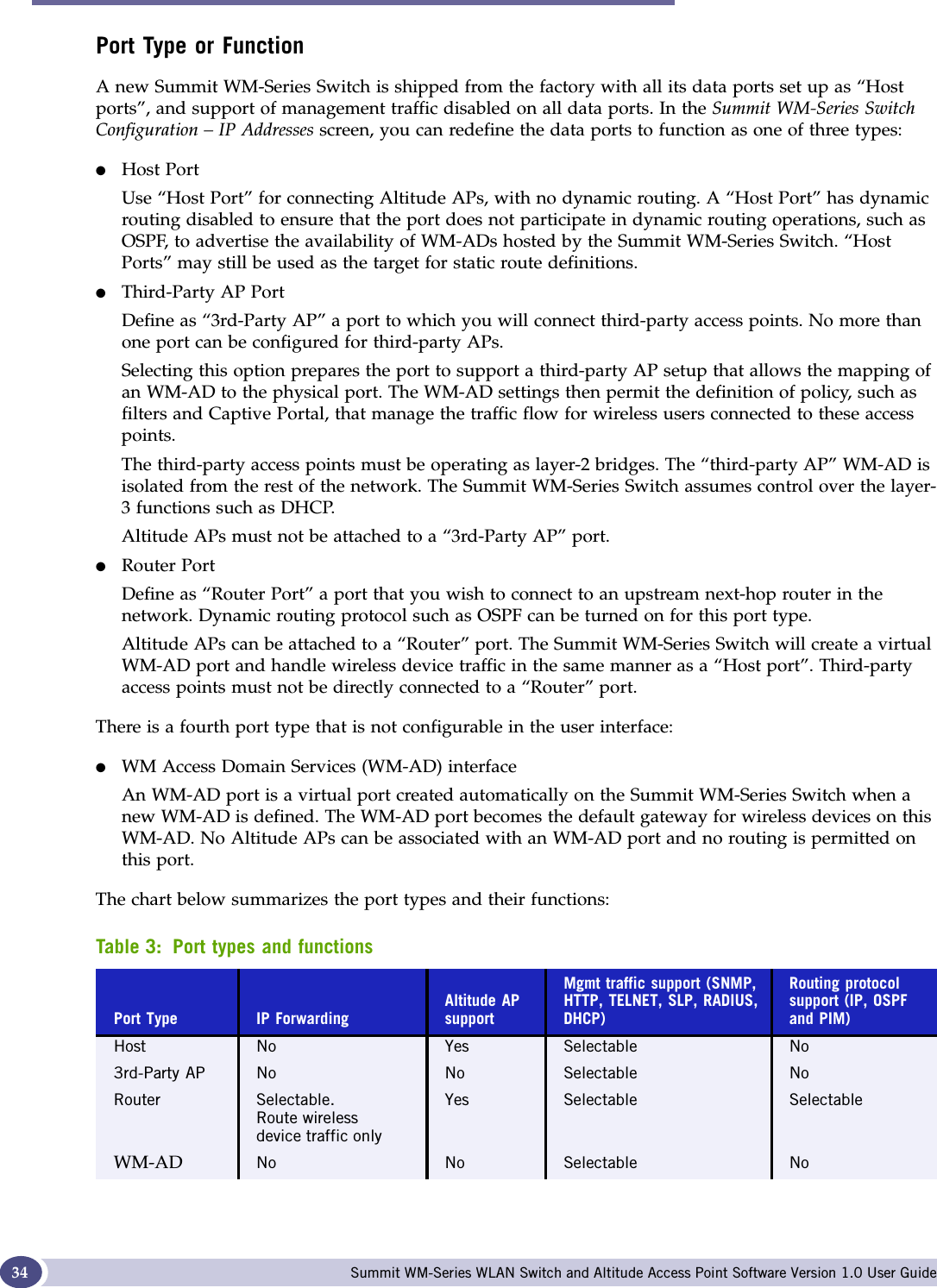
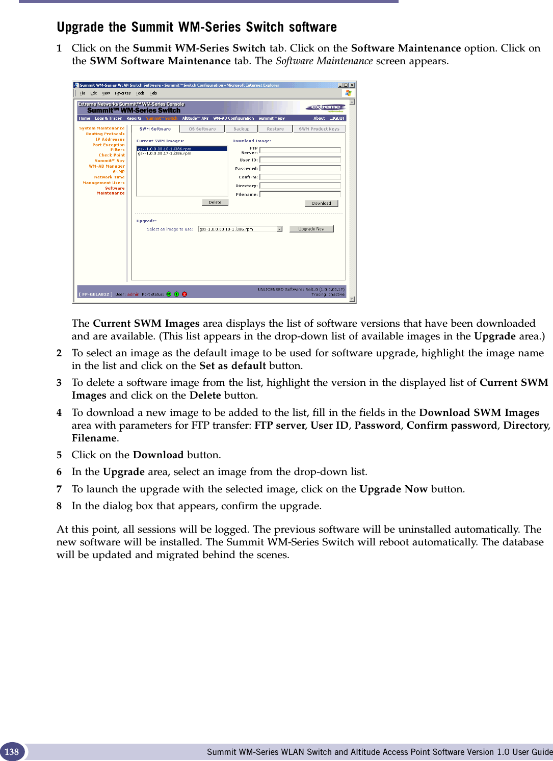
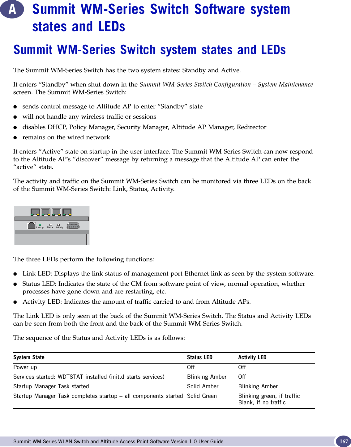
![Altitude AP: startup Summit WM-Series WLAN Switch and Altitude Access Point Software Version 1.0 User Guide48Registration after discoveryAny of the discovery steps 2 through 5 can inform the Altitude AP of a list of multiple IP addresses to which the Altitude AP may attempt to connect. Once the Altitude AP has “discovered” these addresses, it sends out connection requests to all of them simultaneously. It will attempt to register only with the first which responds to its request.When the Altitude AP obtains the IP address of the Summit WM-Series Switch, it connects and registers, sending its serial number identifier to the Summit WM-Series Switch, and receiving from the Summit WM-Series Switch a port IP address and binding key. Once a Altitude AP is registered with a Summit WM-Series Switch:●it appears in the Altitude AP Access Approval screen. You can check its status in this screen. If the registration mode was “Approved only” then the status will be “Pending”. You must modify it to “Approved”.●it appears in the side list in the Altitude AP Configuration: Properties screen, where you can modify the properties and radio parameters.●its two radios appear as available choices in the WM Access Domain Configuration: Topology screen, when you are setting up a WM-AD (up to four WM-ADs for each radio).Before a registered Altitude AP can handle wireless traffic, you must set up a WM-AD definition and assign the Altitude AP's radios to a WM-AD. See Chapter 6.Discovery and registration: Altitude AP LED sequenceAs the Altitude AP is powered on and boots up, you can follow its progress through the registration process by observing the LED sequence described below. The Status LED (center) also indicates power: dark when unit is off and green (solid) when the AP has completed discovery and is operational.The Altitude AP boot sequence is described below:1When powered on, the Altitude AP status LED turns from dark to green briefly. Status LED: green (solid) then to dark before beginning boot sequence.2The Altitude AP performs a self-test. Status LED: red (solid) if POST failed.3The “Discovery” mode: the Altitude AP sends a request to the DHCP server on the enterprise network for the location of the Summit WM-Series Switch (as described above.)Status LED: orange (solid) while searching (“Discovery”)Status LED: red-orange (alternate blink) if DHCP server not found on networkStatus LED: green-orange (alternate blink) if SLP issues in failed discovery.6WDWXV/('/HIW/('*+]UDGLRDFWLYLW\5LJKW/('*+]UDGLRDFWLYLW\](https://usermanual.wiki/Extreme-Networks/A3502A.USERS-MANUAL/User-Guide-683282-Page-48.png)


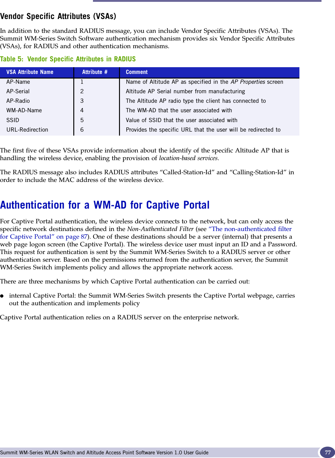
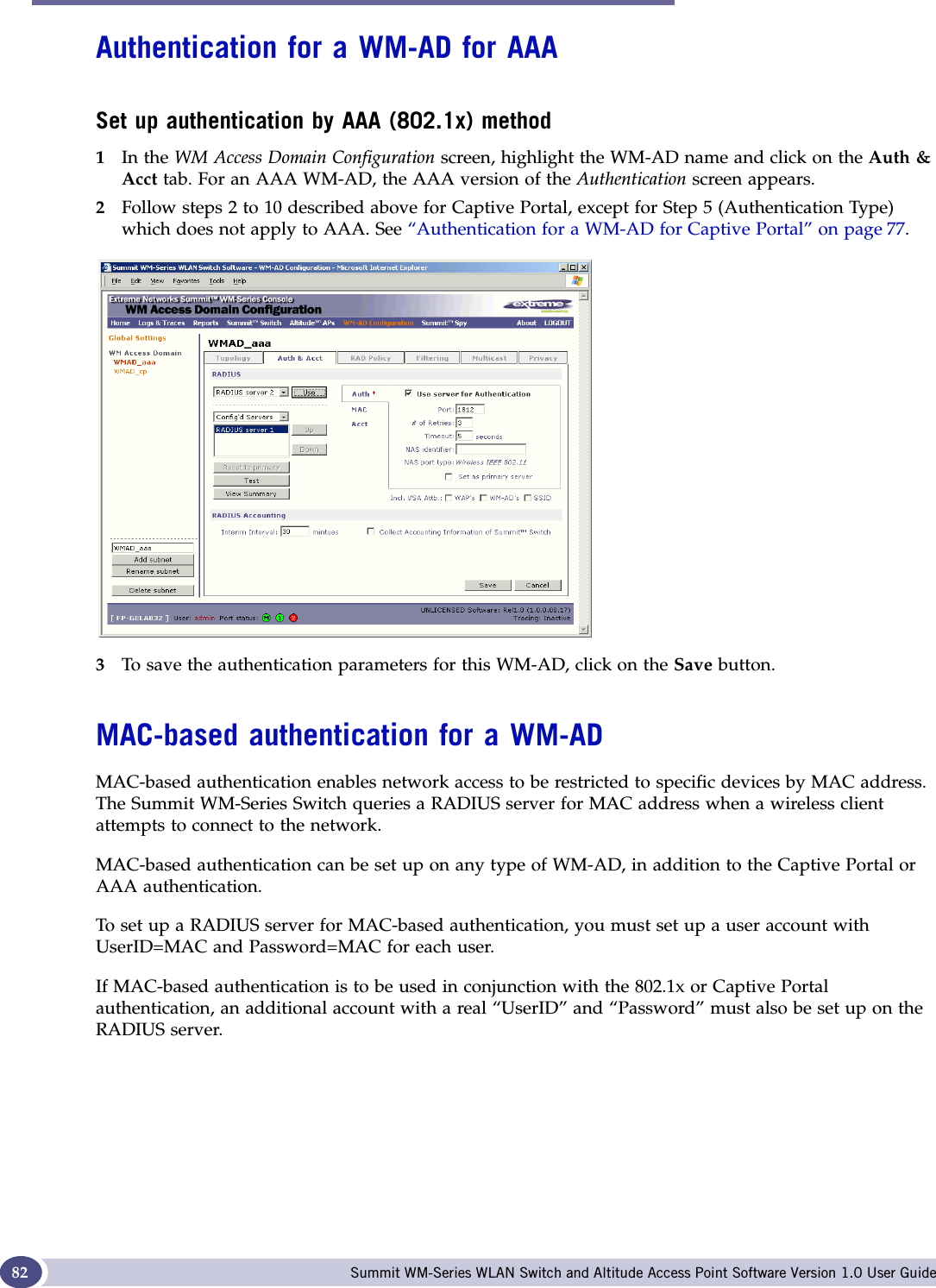
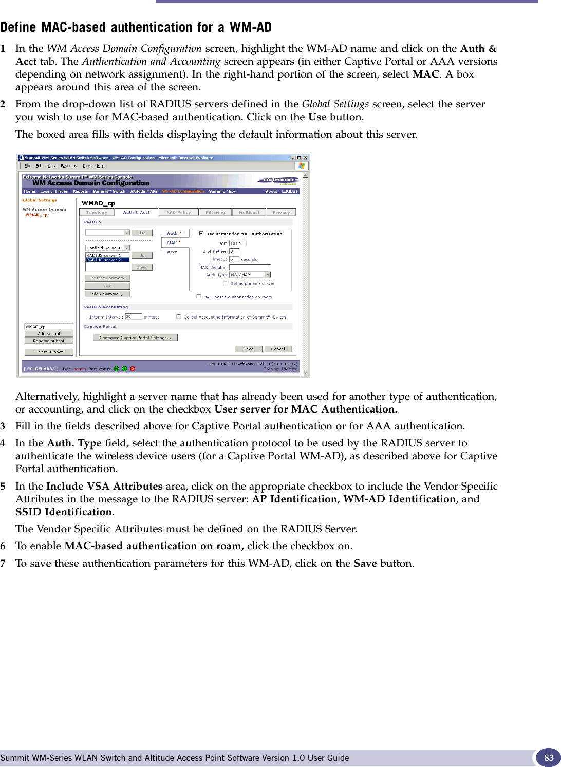
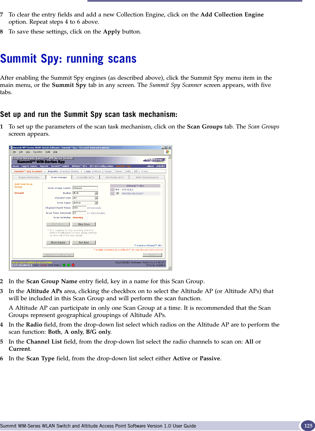
![Authentication for a WM-AD Summit WM-Series WLAN Switch and Altitude Access Point Software Version 1.0 User Guide 79The server name now appears in the list of configured servers (beside the Up and Down buttons)where it can be prioritized for RADIUS redundancy. It can also be assigned again for MAC-based authentication or accounting purposes. A red asterisk appears in the right-hand list, showing that a server has been assigned.4Fill in the following fields:5In the Auth. Type field, select the authentication protocol to be used by the RADIUS server to authenticate the wireless device users (for a WM-AD with Captive Portal authentication).6In the Include VSA Attributes area, click on the appropriate checkbox to include the Vendor Specific Attributes in the message to the RADIUS server: AP Identification,WM-AD Identification, and SSID Identification.The Vendor Specific Attributes must be defined on the RADIUS Server.7If appropriate, click the Set as primary server checkbox on.8To save this configuration, click on Save.NOTEIf you have already assigned a server to either MAC-based authentication or accounting, and wish to use it again for authentication, highlight its name in the list beside the Up and Down buttons. Click the Use server for Authentication checkbox on. The boxed area populates with fields about this server.Define the RADIUS server priority for RADIUS redundancyIf more than one server has been defined for any type of authentication, you can define the priority of the servers in the case of failover. 1Select from the drop-down list: Configured Servers, Authentication Servers, MAC Servers, Accounting Servers.2Highlight a RADIUS server in the list and use the Up or Down key to change the order. The first server in the list is the active one. In the event of a failover of the main RADIUS server (if no response after the set number of retries), then the other servers in the list will be polled on a round-robin basis until one responds.Port # The port used to access the RADIUS server (default: 1812)# of Retries Number of times the Summit WM-Series Switch will attempt to access the RADIUS serverTimeout The maximum time that a Summit WM-Series Switch will wait for a response from the RADIUS server before attempting againNAS Identifier Network Access Server (NAS) identifier, a RADIUS attribute that identifies the server responsible for passing information to designated RADIUS Servers and then acting on the response returned. [Optional] PAP (Password Authentication Protocol) CHAP (Challenge Handshake Authentication Protocol)MS CHAP (Windows-specific version of CHAP)MS CHAP v2 (Windows-specific version of CHAP, version 2)](https://usermanual.wiki/Extreme-Networks/A3502A.USERS-MANUAL/User-Guide-683282-Page-79.png)
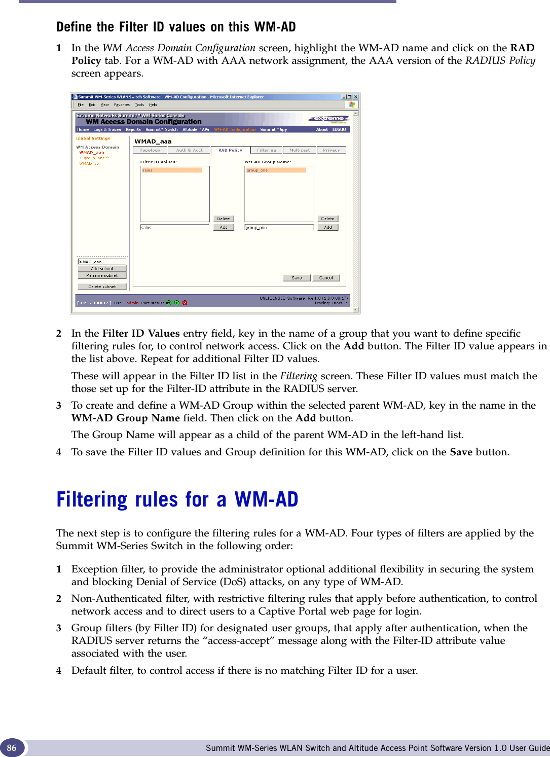
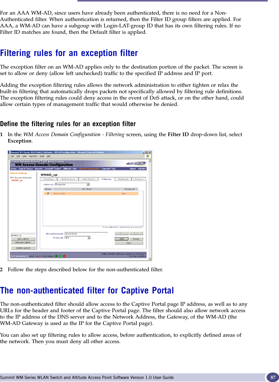
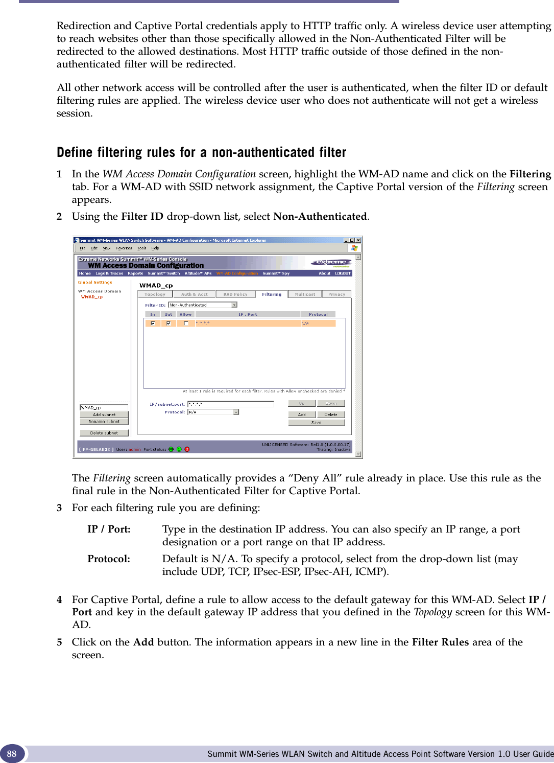
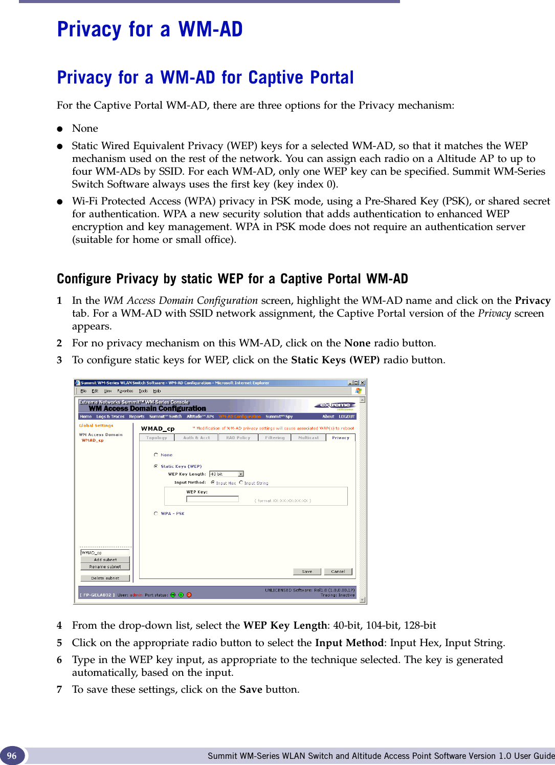
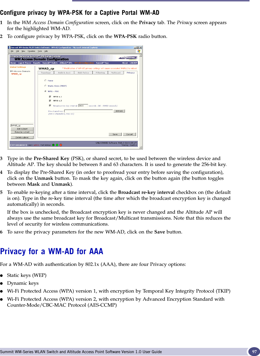
![Filtering rules for a WM-AD Summit WM-Series WLAN Switch and Altitude Access Point Software Version 1.0 User Guide 896Highlight the new filtering rule and fill in (or leave unchecked) the three checkboxes in the combinations that define the traffic access:For Captive Portal, to allow access to the defined IP address, check all three boxes on.7Edit the order of a filtering rule by highlighting the line and clicking on the Up and Down buttons. The filtering rules are executed in the order defined here.8To save the filtering rules, click on the Save button.Non-authenticated filters: examplesA basic Non-Authenticated filter for Captive Portal should have three rules in this order:If you put URLs in the header and footer of the Captive Portal page, you must include a filtering rule to allow traffic to each of these URLs. Put these rules above the “deny everything” rule.Here is another example of a Non-Authenticated Filter that adds two more filtering rules: one denies access to a specific IP address, and the next rule allows only HTTP traffic, before denying all other access:In: Click checkbox on to refer to traffic from the wireless device that is trying to get on the network (“going to” the network)Out: Click checkbox on to refer to traffic from the network host that is trying to get to a wireless device. (“coming from” the network)Allow: Click checkbox on to allow. Leave unchecked to disallow.In Out Allow IP / Port Descriptionx x x IP address of the Default GatewayAllow all incoming wireless devices access to the default gateway of the WM-AD.x x x IP address of the DNS ServerAllow all incoming wireless devices access to the DNS server of the WM-AD.x x *.*.*.* Deny everything else.In Out Allow IP / Port Descriptionx x x IP address of the Default GatewayAllow all incoming wireless devices access to the default gateway of the WM-AD.x x x IP address of the DNS ServerAllow all incoming wireless devices access to the DNS server of the WM-AD.x x [a specific IP address, or address plus range]Deny all traffic to a specific IP address, or to a specific IP address range (such as :0/24).x x x *.*.*.*:80 Allow all port 80 (HTTP) traffic.x x *.*.*.* Deny everything else.](https://usermanual.wiki/Extreme-Networks/A3502A.USERS-MANUAL/User-Guide-683282-Page-89.png)
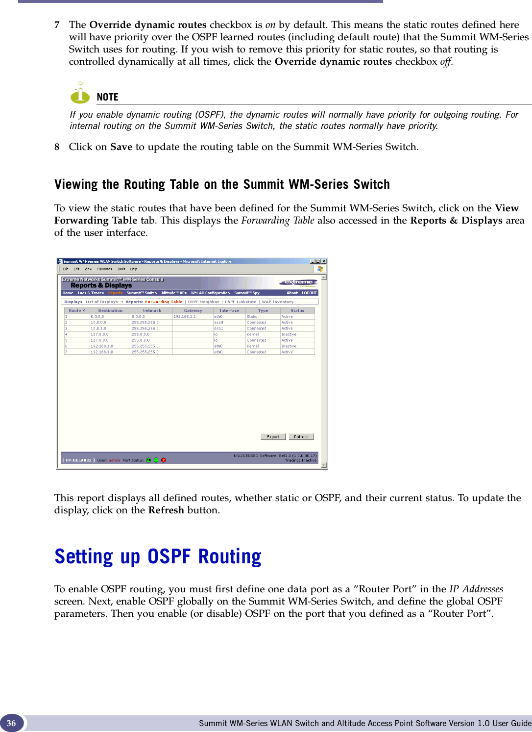
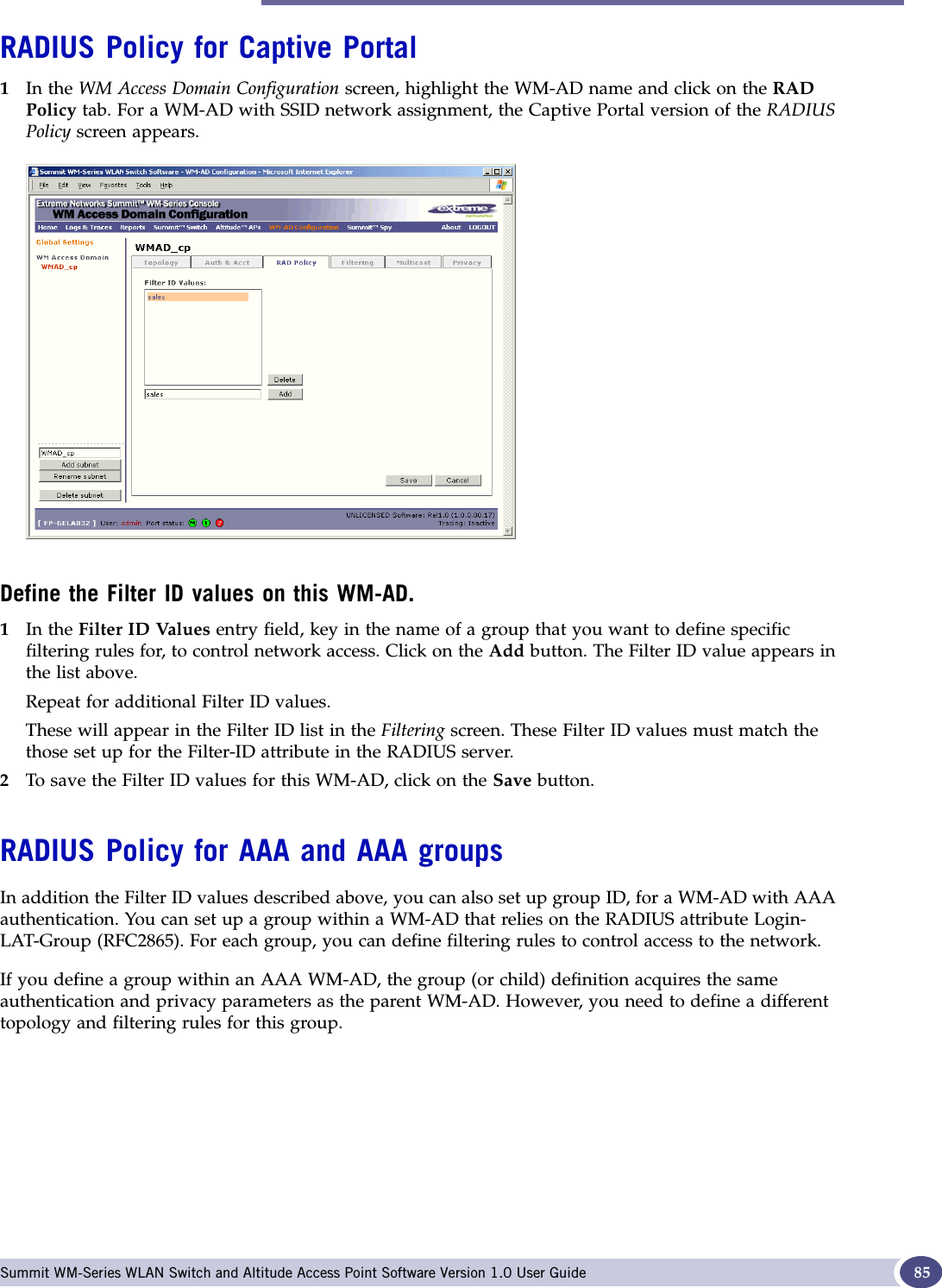
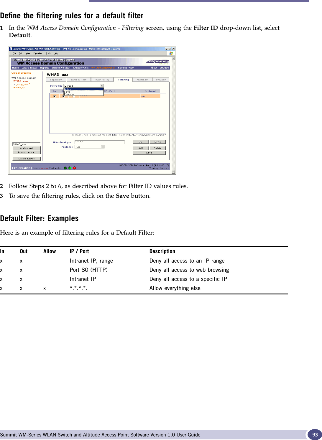
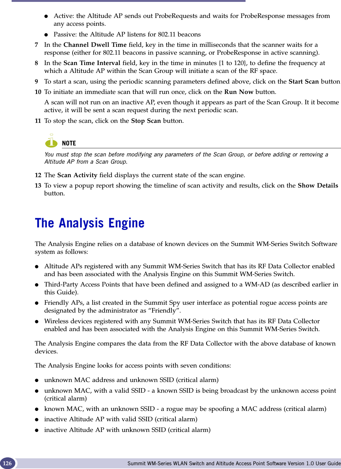
![Filtering rules for a WM-AD Summit WM-Series WLAN Switch and Altitude Access Point Software Version 1.0 User Guide 91Define filtering rules for a Filter ID group1In the WM Access Domain Configuration screen, click on the Filtering tab. The Filtering screen appears for the highlighted WM-AD. 2Using the Filter ID drop-down list, select one of the names you defined in the Filter ID Values field in the Authentication screen [one of your enterprise's user groups, such as Sales, Engineering, Teacher, Guest....]The screen automatically provides a “Deny All” rule already in place. This can be modified to “Allow All”, if appropriate to the network access needs for this WM-AD.3Select one of the following as the basis for each filtering rule you are defining:4Click on the Add button. The information appears in a new line in the Filter Rules area of the screen. 5Highlight the new filtering rule and fill in (or leave unchecked) the three checkboxes in the combinations that define the traffic access:6Edit the order of a filtering rule by highlighting the line and clicking on the Up and Down buttons. The filtering rules are executed in the order defined here7To save the filtering rules, click on the Save button.IP / Port: Type in the destination IP address, and if desired, the port designation on that IP address.Protocol: Select from the drop-down list (may include UDP, TCP, IPsec-ESP, IPsec-AH, ICMP)In: Click checkbox on to refer to traffic from the wireless device that is trying to get on the network (“going to” to network)Out: Click checkbox on to refer to traffic from the network host that is trying to get to a wireless device. (“coming from” the network)Allow: Click checkbox on to allow. Leave unchecked to disallow](https://usermanual.wiki/Extreme-Networks/A3502A.USERS-MANUAL/User-Guide-683282-Page-91.png)
![WM Access Domain Configuration Summit WM-Series WLAN Switch and Altitude Access Point Software Version 1.0 User Guide92Filtering Rules by Filter ID: ExamplesBelow are two examples of possible filtering rules for a Filter ID. The first disallows only some specific access before allowing everything else.The second example does the opposite of the first example. It allows only some specific access and denies everything else. Filtering rules for a default filterAfter authentication of the wireless device user, the default filter will apply only after:●no match is found for the Exception flittering rules●no Filter ID attribute value is returned by the authentication server for this user●no match is found on the Summit WM-Series Switch for a Filter ID valueThe final rule in the Default filter should be a catch-all for any traffic that did not match a filter. A final “allow all” rule in a Default Filter will ensure that a packet is not dropped entirely if no other match can be found.In Out Allow IP / Port Descriptionx x *.*.*.*:22-23 Deny all telnet sessionsx x [specific IP address, range] Deny all traffic to a specific IP address or address rangex x x *.*.*.*. Allow everything elseIn Out Allow IP / Port Descriptionx x x [specific IP address, range] Allow traffic to a specific IP address or address range.x x *.*.*.*. Deny everything else.](https://usermanual.wiki/Extreme-Networks/A3502A.USERS-MANUAL/User-Guide-683282-Page-92.png)
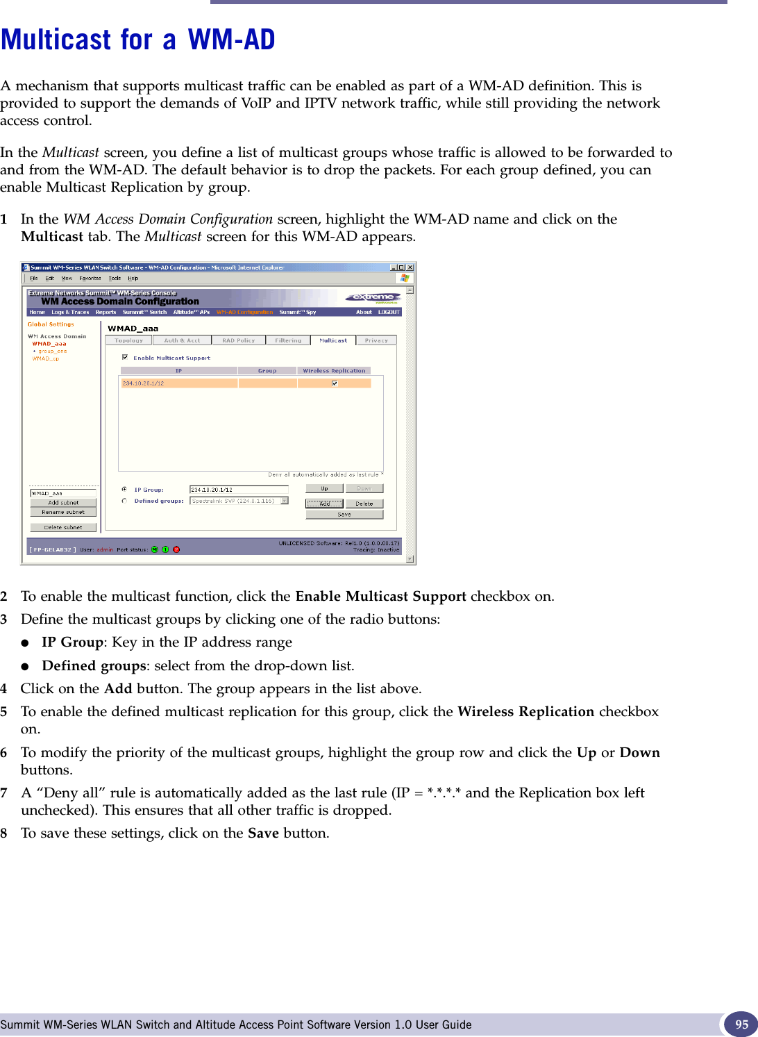
![WM Access Domain Configuration Summit WM-Series WLAN Switch and Altitude Access Point Software Version 1.0 User Guide94Here is another example of filtering rules for a Default Filter:Filtering Rules for an AAA Group WM-ADIf you defined a child group for an AAA WM-AD, it will have the same authentication parameters and Filter IDs as the parent WM-AD. However, you can define different filtering rules for these Filters IDs in the child configuration than in the parent configuration. 1In the WM Access Domain Configuration screen, highlight the WM-AD group name in the list and click on the Filtering tab. The Filtering screen for this WM-AD group appears.2Follow Steps 2 to 6, as described above for a parent WM-AD.3To save the filtering rules, click on the Save button.Filtering rules between two wireless devicesTraffic from two wireless devices that are on the same WM-AD and are connected to the same Altitude AP will pass through the Summit WM-Series Switch and therefore be subject to filtering policy. You can set up filtering rules that allow each wireless device access to the default gateway, but prevent each device from communicating each other. Add the following two rules to a Filter ID filter before allowing everything else:In Out Allow IP / Port DescriptionxPort 80 (HTTP) on host IP Deny all incoming wireless devices access to web browsing the hostxIntranet IP 10.3.0.20, ports 10-30 Deny all traffic from the network to the wireless devices on the port range, such as TELNET (port 23) or FTP (port 21)x x Intranet IP 10.3.0.20 Allow all other traffic from the wireless devices to the Intranet networkx x Intranet IP 10.3.0.20 Allow all other traffic from Intranet network to wireless devicesx x x *.*.*.*. Allow everything elseIn Out Allow IP / Port Descriptionx x x [Intranet IP] Allow access to the Gateway IP address of the WM-AD onlyx x [Intranet IP, range] Deny all access to the WM-AD subnet range 0/24x x x *.*.*.*. Allow everything else](https://usermanual.wiki/Extreme-Networks/A3502A.USERS-MANUAL/User-Guide-683282-Page-94.png)
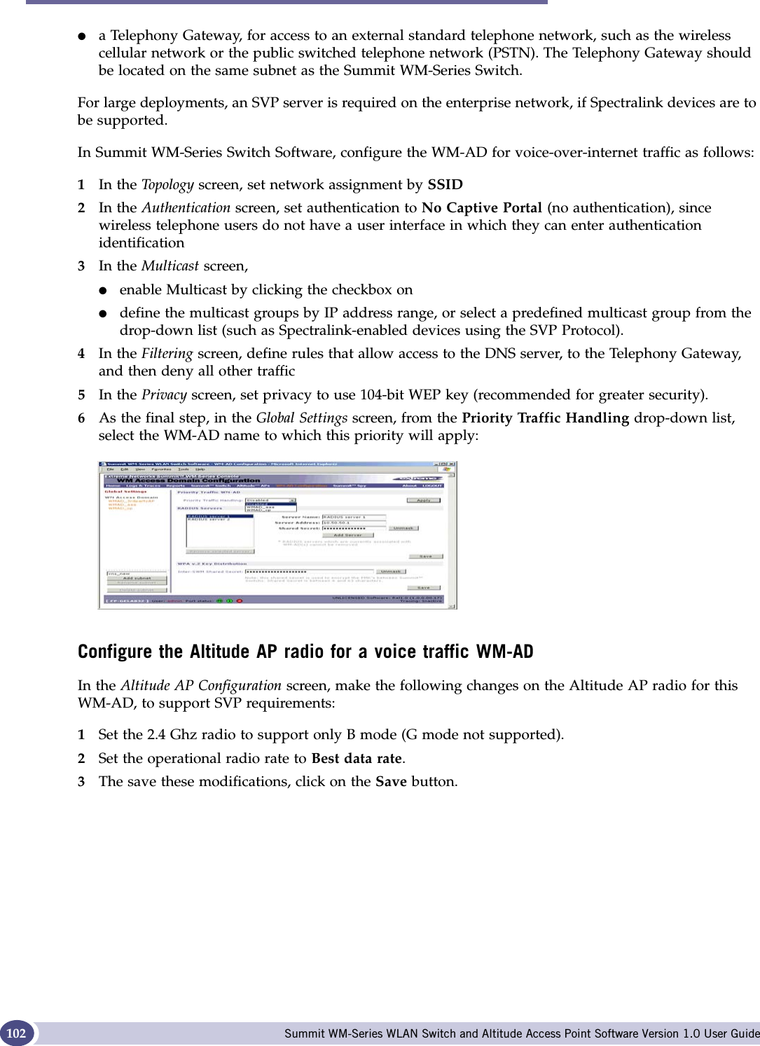
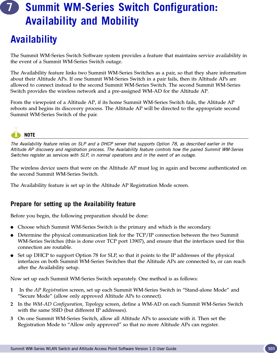
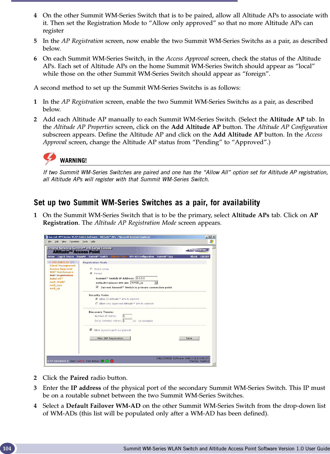
![Availability Summit WM-Series WLAN Switch and Altitude Access Point Software Version 1.0 User Guide 1055Since this Summit WM-Series Switch is to be the primary connection point, click the checkbox on.6Set the Security Mode to “Allow Approved” by clicking the radio button. [recommended after initial set up for paired Summit WM-Series Switches]7To save these settings, click on the Save button.On the Summit WM-Series Switch that is to be the secondary one, repeat Steps 1 to 7, with these exceptions:●In Step 3, enter the IP address of the Management port or physical port of the primary Summit WM-Series Switch.●In Step 5, leave the primary connection point checkbox unchecked.NOTEWhen two Summit WM-Series Switches have been paired as described above, each Summit WM-Series Switch's registered Altitude APs will appear as “foreign” in the list of available Altitude APs when configuring a WM-AD topology.View the Altitude AP Availability DisplayWhen the Altitude AP Configuration: AP Registration Mode screen has been saved for the Summit WM-Series Switch in Paired Mode, the Altitude AP Availability display will show the status of both “local” and “foreign” Altitude APs for that Summit WM-Series Switch.In normal operations, when Availability is enabled, the “local” Altitude APs are green, and the “foreign” Altitude APs are red. If the other Summit WM-Series Switch fails, and the “foreign” Altitude APs connect to the current Summit WM-Series Switch, the display will show all Altitude APs as green. If the Altitude APs are not attached they do not appear in the report.](https://usermanual.wiki/Extreme-Networks/A3502A.USERS-MANUAL/User-Guide-683282-Page-105.png)

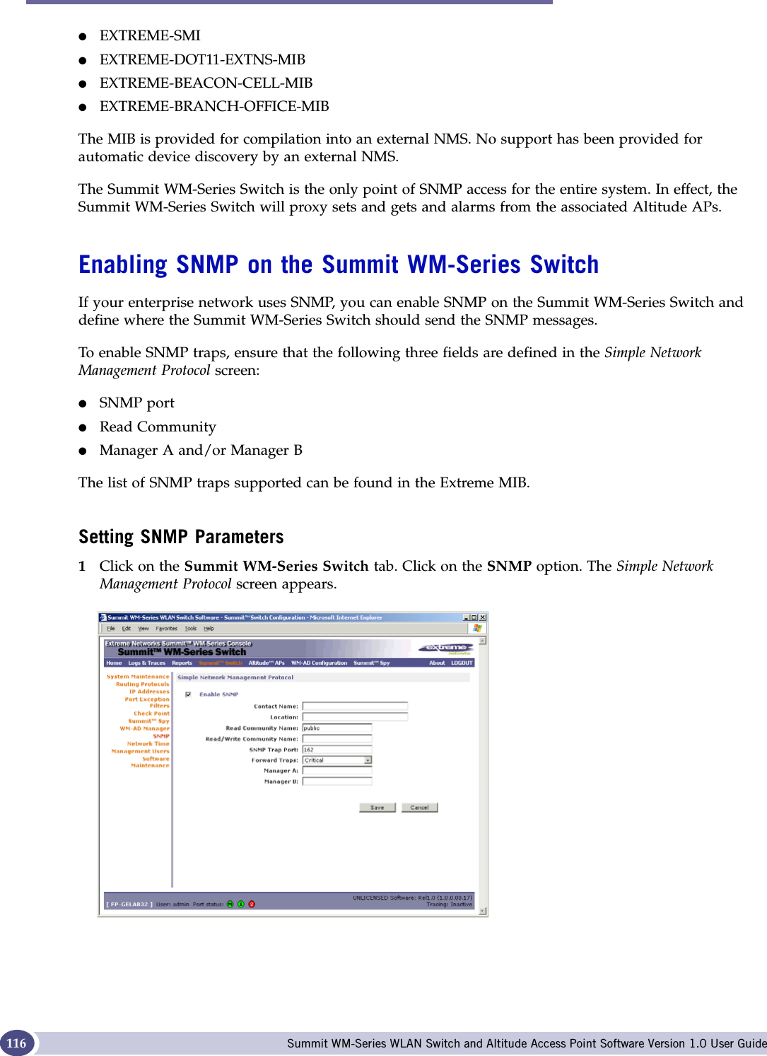
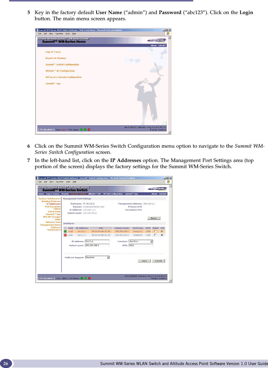
![Setting up SNMP Summit WM-Series WLAN Switch and Altitude Access Point Software Version 1.0 User Guide 1172Key in:Contact Name: The name of SNMP administrator.Location: Location of the SNMP administration machine (descriptive).Read Community Name: Key in the password for Read activity.Read/Write Community Name:Key in the password for Read/Write activity. (Write ability is not supported.)SNMP Port: Key in the destination port for SNMP traps. The industry standard is 162. [If left blank, no traps are generated.]Forward Traps: From the drop-down list, select the severity level of the traps to be forwarded: Informational, Minor, Major, Critical.Manager A: The IP address of the specific machine on the network where the SNMP traps are monitored.Manager B: The IP address of a second machine on the network where the SNMP traps are monitored, if Manager A is not available.](https://usermanual.wiki/Extreme-Networks/A3502A.USERS-MANUAL/User-Guide-683282-Page-117.png)


![G Summit WM-Series WLAN Switch and Altitude Access Point Software Version 1.0 User Guide 151Fit, thin and fat APs A thin AP architecture uses two components: an access point that is essentially a stripped-down radio and a centralized management controller that handles the other WLAN system functions. Wired network switches are also required. A fit AP, a variation of the thin AP, handles the RF and encryption, while the central management controller, aware of the wireless users' identities and locations, handles secure roaming, quality of service, and user authentication. The central management controller also handles AP configuration and management. A fat (or thick) AP architecture concentrates all the WLAN intelligence in the access point. The AP handles the radio frequency (RF) communication, as well as authenticating users, encrypting communications, secure roaming, WLAN management, and in some cases, network routing. FQDN Fully Qualified Domain Name. A “friendly” designation of a computer, of the general form computer.[subnetwork.].organization.domain. The FQDN names must be translated into an IP address in order for the resource to be found on a network, usually performed by a Domain Name Server.FTM Forwarding Table ManagerFTP File Transfer ProtocolGGateway In the wireless world, an access point with additional software capabilities such as providing NAT and DHCP. Gateways may also provide VPN support, roaming, firewalls, various levels of security, etc.Gigabit Ethernet The high data rate of the Ethernet standard, supporting data rates of 1 gigabit (1,000 megabits) per second.GUI Graphical User InterfaceHHeartbeat message A heartbeat message is a UDP data packet used to monitor a data connection, polling to see if the connection is still alive.In general terms, a heartbeat is a signal emitted at regular intervals by software to demonstrate that it is still alive. In networking, a heartbeat is the signal emitted by a Level 2 Ethernet transceiver at the end of every packet to show that the collision-detection circuit is still connected.Host (1) A computer (usually containing data) that is accessed by a user working on a remote terminal, connected by modems and telephone lines. (2) A computer that is connected to a TCP/IP network, including the Internet. Each host has a unique IP address.F (Continued)](https://usermanual.wiki/Extreme-Networks/A3502A.USERS-MANUAL/User-Guide-683282-Page-151.png)

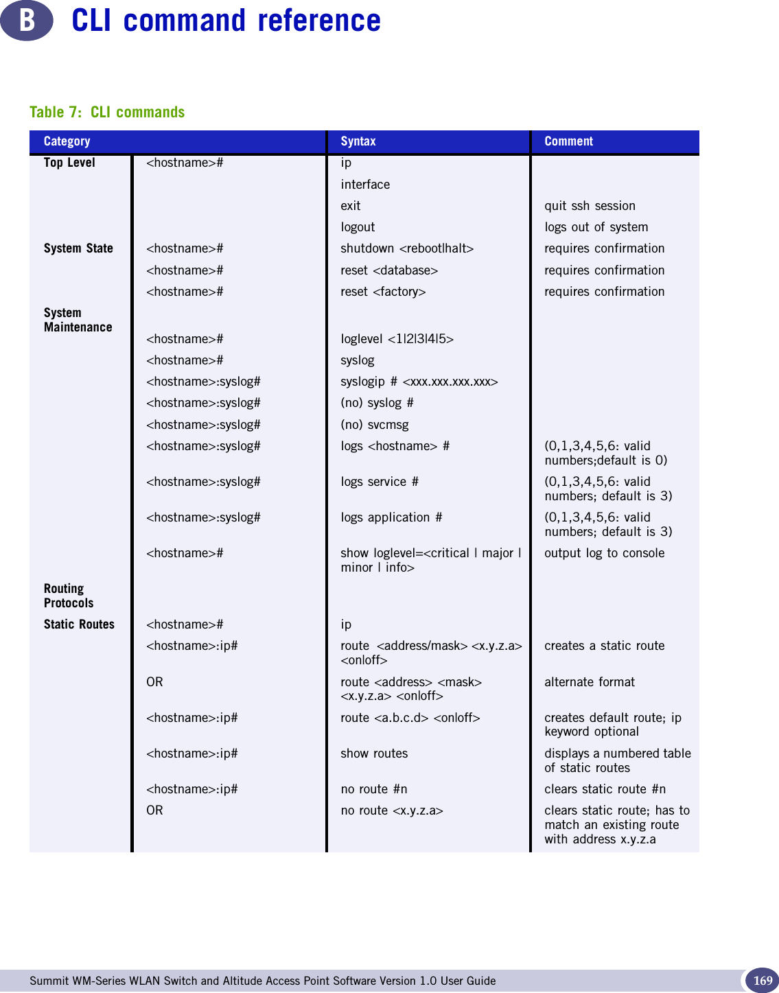
![CLI command reference Summit WM-Series WLAN Switch and Altitude Access Point Software Version 1.0 User Guide170OSPF <hostname># ip<hostname>:ip# (no) protocol ospf<hostname>:ip# ospf only 1 protocol can be enabled on the AC<hostname>:ospf# routerid <value>area <area-id>areatype <default|stub|nssa>config ospfinterface <0|1|2|3><hostname>:ospf.0# (no) ospfinterface Port has to be made router port during esa configurationlinkcost <val|default>auth <on|off>authkey <password>hello <val|default>dead <val|default>retx <val|default>txdelay <val|default>IP AddressesManagement Port<hostname># interface<hostname>:interface:# eth0 selects interface to configure<hostname>:interface: eth0# hostname '<string>' hostname<hostname>:interface: eth0# domain '<string>' domain name<hostname>:interface :eth0# ip <xxx.xxx.xxx.xxx>/mask enter management IP addressOR ip <xxx.xxx.xxx.xxx> mask <255.255.255.255>enter network mask<hostname>:interface: eth0# gateway <xxx.xxx.xxx.xxx> enter gateway address<hostname>:interface: eth0# (no) nameserver # <x.y.z.a> (opt) domain controller addressesexit return to <hostname>(if)#esa Ports <hostname>:interface:# esa [0-3]<hostname>:interface: esa-X# ip <xxx.xxx.xxx.xxx>/mask enter IXP port IP addressOR ip <xxx.xxx.xxx.xxx> mask <255.255.255.255>enter network mask<hostname>:interface: esa-X# #mtu <integer> has to be 64 <= X <= 1500<hostname>:interface: esa-X# function [host | ap | router] set interface type<hostname>:interface: esa-X# (no) mgmt enable / disable management traffic<hostname>:interface: esa-X# (no) regslp register interface with slpTable 7: CLI commands (Continued)Category Syntax Comment](https://usermanual.wiki/Extreme-Networks/A3502A.USERS-MANUAL/User-Guide-683282-Page-170.png)
![Summit WM-Series WLAN Switch and Altitude Access Point Software Version 1.0 User Guide 171File Management<hostname># show backup [filename|number] list back-up files on system<hostname># show cdrs [dir] [filename|number]list CDRs available on system<hostname># show restore list restore files on system<hostname># show upgrade list upgrade files on system<hostname># show osupgrade list os upgrade files on system<hostname># show apup list ap image upgrade files on system<hostname># show bootrom list ap bootrom image files on systemBack-up system<hostname># backup <cdrs|configuration|logs|audit|all>RestoreBack-up<hostname># restore <filename|number>Upgrade CM <hostname># upgrade ac <filename|number>Upgrade OS <hostname># upgrade os <filename|number>Upgrade AP <hostname># upgrade apup <filename|number> ap <bserial#, …, bserial#>Upgrade Product Key<hostname># upgrade key executes script to apply product keyUpload / Download<hostname># copy backup <server> <user> <dir> <file>copy restore <server> <user> <dir> <file>copy upgrade <server> <user> <dir> <file>copy osupgrade <server> <user> <dir> <file>copy cdrs <server> <user> <dir> <file>copy apup <server> <user> <dir> <file>copy key <server> <user><dir> <file>loads key onto serverno backup <filename|number> deletes backup fileno restore <filename|number> deletes restore fileno upgrade <filename|number> deletes upgrade fileno apup <filename|number> deletes ap upgrade imageno cdr <filename|number> deletes cdr recordno key deletes key – only available from the CLITable 7: CLI commands (Continued)Category Syntax Comment](https://usermanual.wiki/Extreme-Networks/A3502A.USERS-MANUAL/User-Guide-683282-Page-171.png)
![CLI command reference Summit WM-Series WLAN Switch and Altitude Access Point Software Version 1.0 User Guide172Users <hostname># users<hostname>:users#id <userid> [admin] [enable|disable]end of command, enter password & confirm password<hostname>:users#id no id <userid> confirm delete<hostname>:users#id (no) logon <userid> disable / enable user access to management system; confirm action<hostname>:users#id pwd id <userid> change password for userid; enter password & confirm passwordDiagnostics <hostname># ping <target_ip> issues 4 iCMP ping messages to target IP address<hostname># traceroute <target_ip> attempts to trace route to target IP addressradtest <wm-ad_name> <username> <password>][tracing]tests RADIUS authentication settingsradtest_mba <wm-ad> <mac> <ap_bss_mac> <ap_eth_mac> [tracing]tests RADIUS MAC-based authenticationAltitude APs <hostname># show ap displays list of AP serial numbersTable 7: CLI commands (Continued)Category Syntax Comment](https://usermanual.wiki/Extreme-Networks/A3502A.USERS-MANUAL/User-Guide-683282-Page-172.png)


![RADIUS Attributes Summit WM-Series WLAN Switch and Altitude Access Point Software Version 1.0 User Guide184RADIUS AccountingAccount-Start PacketThe following table lists the information elements (including VSAs) supported in a RADIUS Start message, issued by Summit WM-Series Switch Software, with RADIUS Accounting enabled:Attribute NO. RAD. Data Type NameAcct-Session-Id 44 string mu_session_id User-Name 1string mu_user_idFilter-Id 11 string Filter-Id (Accept-response)Acct-Interim-Interval 85 integer (Accept-response/GUI input)Session-Timeout 27 integer (Accept-response/GUI input)Class 25 octets (Accept-response)Login-LAT-Group 36 octets (Accept-response)Acct-Status-Type 40 integer StartAcct-Authentic 45 integer Radius/Local/RemoteFramed-IP-Address 8ipaddr Mu_ip_addressConnect-Info 77 string 802.11 a[b][g]NAS-port-type 61 integer 18/19 Called-Station-ID 30 string BP MACCalling-Station-ID 31 string mu_mac_addressAcct-Delay-Time 41 integerBP-Serial VSA string Extreme Networks-AP-Serial BP-Name VSA string Extreme Networks-AP-NameVNS-Name VSA string Extreme Networks-VNS-NameSSID VSA string Extreme Networks-SSID](https://usermanual.wiki/Extreme-Networks/A3502A.USERS-MANUAL/User-Guide-683282-Page-184.png)
![RADIUS Accounting Summit WM-Series WLAN Switch and Altitude Access Point Software Version 1.0 User Guide 185Account-Stop/Interim PacketThe following table lists the information elements (including VSAs) supported in a RADIUS Stop or Interim messages, issued by Summit WM-Series Switch Software, with RADIUS Accounting enabled:Attribute NO. RAD. Data Type NameAcct-Session-Id 44 string mu_session_id User-Name 1string mu_user_idFilter-Id 11 string Filter-Id (Accept-response)Acct-Interim-Interval 85 integer (Accept-response/GUI input)Session-Timeout 27 integer (Accept-response/GUI input)Class 25 octets (Accept-response)Login-LAT-Group 36 octets (Accept-response)Acct-Status-Type 40 integer Stop/Interim-UpdateAcct-Authentic 45 integer Radius/Local/RemoteFramed-IP-Address 8ipaddr Mu_ip_addressConnect-Info 77 string 802.11 a[b][g]NAS-port-type 61 integer 18/19Called-Station-ID 30 string BP MACCalling-Station-ID 31 string mu_mac_addressAcct-Delay-Time 41 integerAcct-Session-Time 46 integerAcct-Input-Packets 47 integerAcct-Output-Packets 49 integerAcct-Input-Octets 42 integerAcct-Output-Octets 43 integerAcct-Input-Gigawords 52 integerAcct-Output-Gigawords 53 integerAcct-Terminate-Cause 49 integerBP-Serial VSA string Extreme Networks-AP-Serial BP-Name VSA string Extreme Networks-AP-NameVNS-Name VSA string Extreme Networks-VNS-NameSSID VSA string Extreme Networks-SSID](https://usermanual.wiki/Extreme-Networks/A3502A.USERS-MANUAL/User-Guide-683282-Page-185.png)
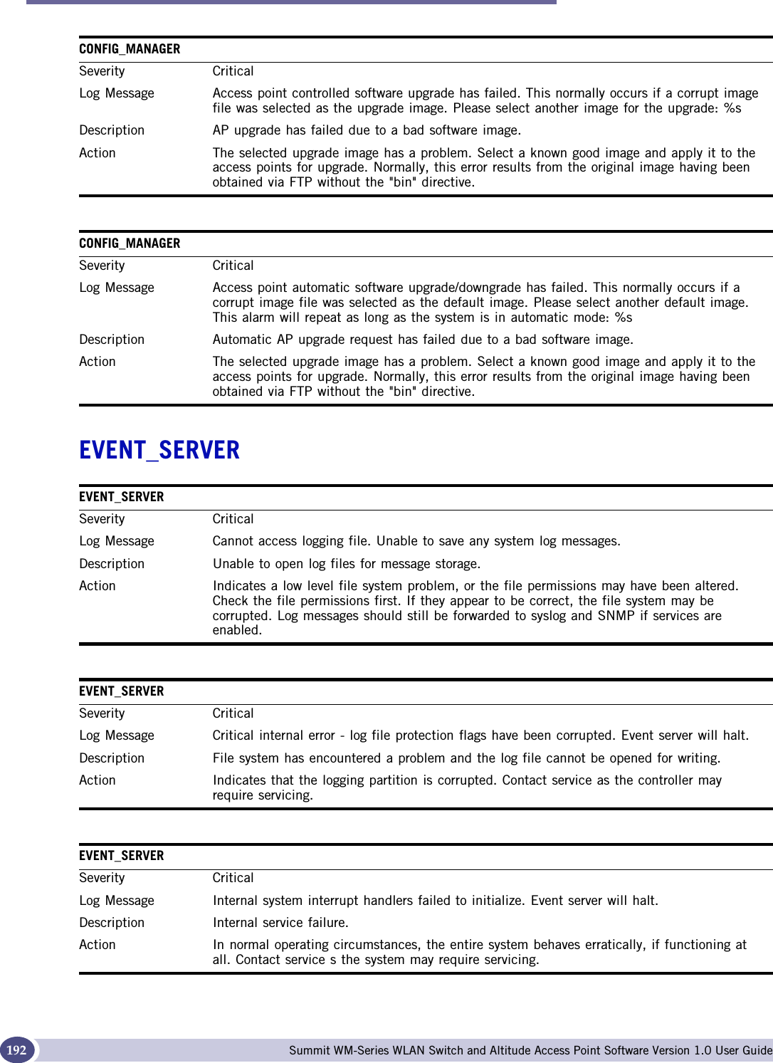
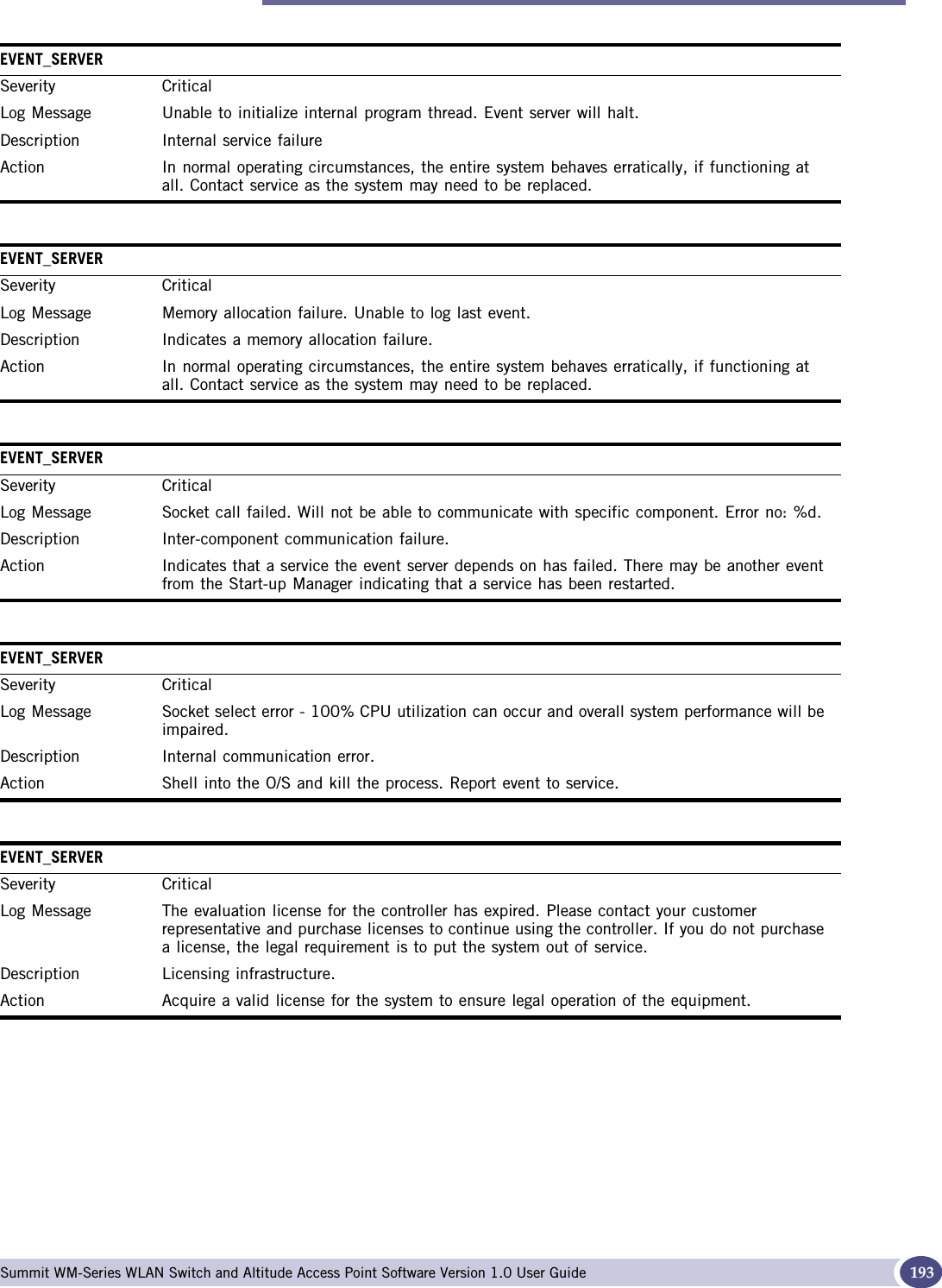
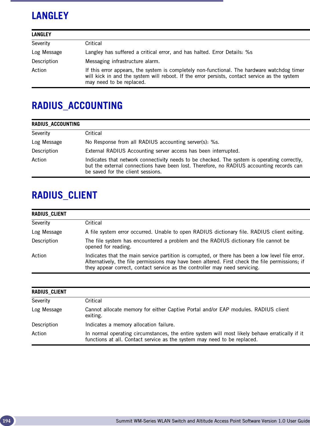
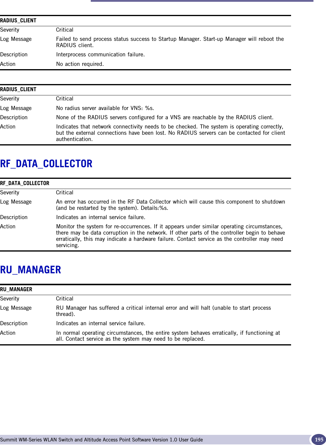

![Major Summit WM-Series WLAN Switch and Altitude Access Point Software Version 1.0 User Guide 209SECURITY_MANAGERSeverity MajorLog Message Unable to create new session tracking tag (token mapping) based on MAC address. Will not be able to process Captive portal authentication request.Description Security Manager service information. Action If this occurs, a client session will fail captive portal authentication. The end user should try to authenticate again. Alternatively, try restarting to the process to see if this clears the problem.SECURITY_MANAGERSeverity MajorLog Message Get next available session tracking tag (token) returns zero. Will not be able to process Captive portal authentication request.Description Security Manager service information. Action If this occurs, a client session will fail captive portal authentication. The end user should try to authenticate again. Alternatively, try restarting to the process to see if this clears the problem.SECURITY_MANAGERSeverity MajorLog Message Error on deleting session tracking tag (token) %d. This will not impact success/failure of authentication request - it may create a memory leak if multiple tokens cannot be deleted.Description Security Manager service information. Action No action required. If the failure frequently re-occurs, it may be useful to restart the process to free lost memory. SECURITY_MANAGERSeverity MajorLog Message Unable to start component [%d]. Services provided by the component will be unavailable.Description System service status message. Action Try restarting the controller to see if that clears the problem. If rebooting does not clear the problem, contact support. Even though the process is down, it may not operationally effect the system. It may impair only parts of the system behavior.SECURITY_MANAGERSeverity MajorLog Message Component [%d] is down. Component will be restarted.Description System service status message. Action No action required.](https://usermanual.wiki/Extreme-Networks/A3502A.USERS-MANUAL/User-Guide-683282-Page-209.png)
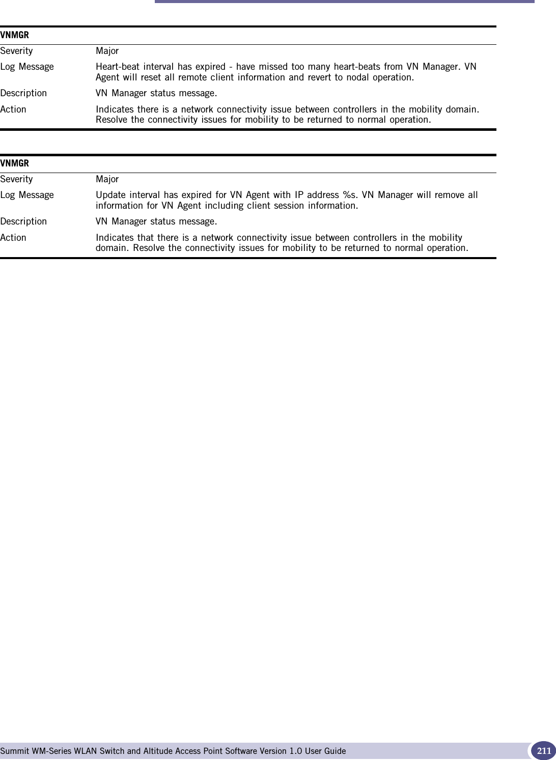
![Logs and Events Summit WM-Series WLAN Switch and Altitude Access Point Software Version 1.0 User Guide210VNMGRSECURITY_MANAGERSeverity MajorLog Message Component [%s] is down. Component will be restarted.Description System service status message. Action No action required. VNMGRSeverity MajorLog Message Configuration error - missing or bad parameters. VN Manager will retry configuration request. VN Manager will not start-up until configuration is successful.Description VN Manager status message. Action Verify that Config Manager is operational. Re-start if process has stopped. Problem should clear without intervention. VNMGRSeverity MajorLog Message Set Configuration data failed. The VNMgr may be restarted.Description VN Manager status message. Action No action required. Process should be restarted without intervention. VNMGRSeverity MajorLog Message Get Configuration data failed. The VNMgr may be restarted.Description VN Manager status message. Action No action required. Process should be restarted without intervention. VNMGRSeverity MajorLog Message VN Manager internal status changed. VN Manager will shutdown and be re-started by the Start-up Manager.Description VN Manager status message. Action VN Manager has been changed from Agent to Manager or vice-versa. No action required. VNMGRSeverity MajorLog Message Received unknown message type %d from Langley (CM socket).Description VN Manager status message. Action No action required.](https://usermanual.wiki/Extreme-Networks/A3502A.USERS-MANUAL/User-Guide-683282-Page-210.png)