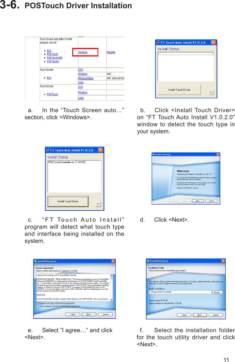
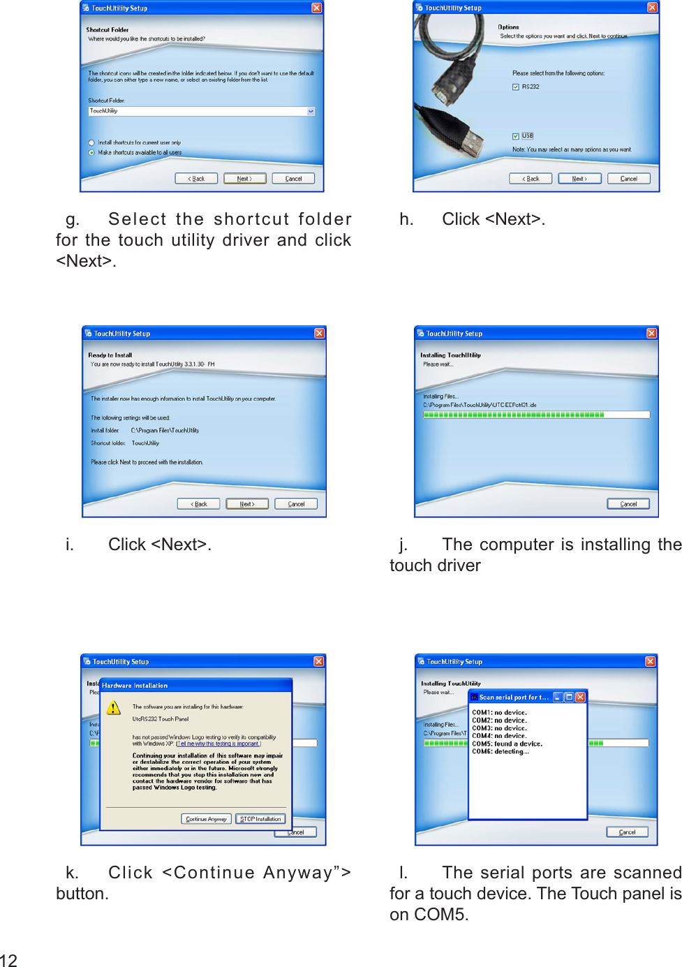
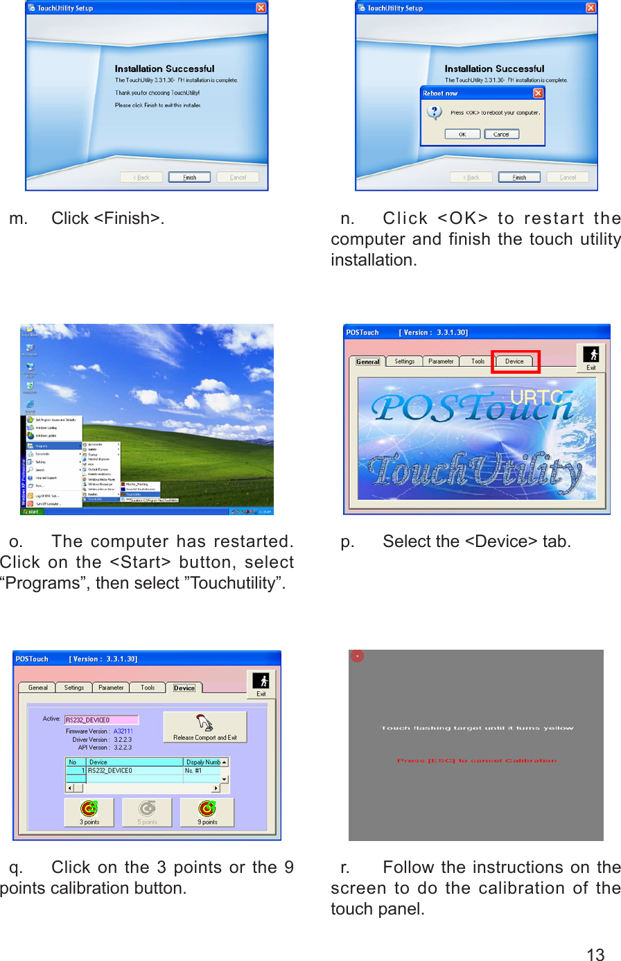
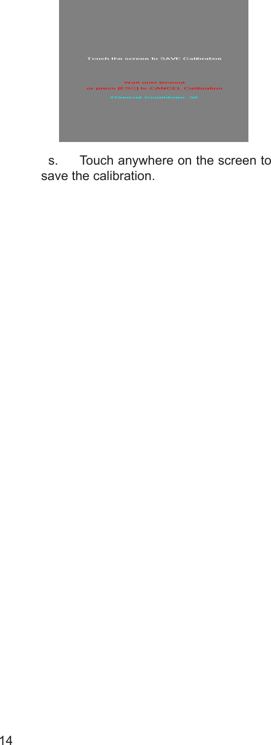
FLYTECH TECHNOLOGY BED-185 Terminal Hardware System User Manual K938S indb
FLYTECH TECHNOLOGY CO., LTD Terminal Hardware System K938S indb
UserManual.wiki
>
FLYTECH TECHNOLOGY
>
BED-185 User Manual
>
manual2
Contents
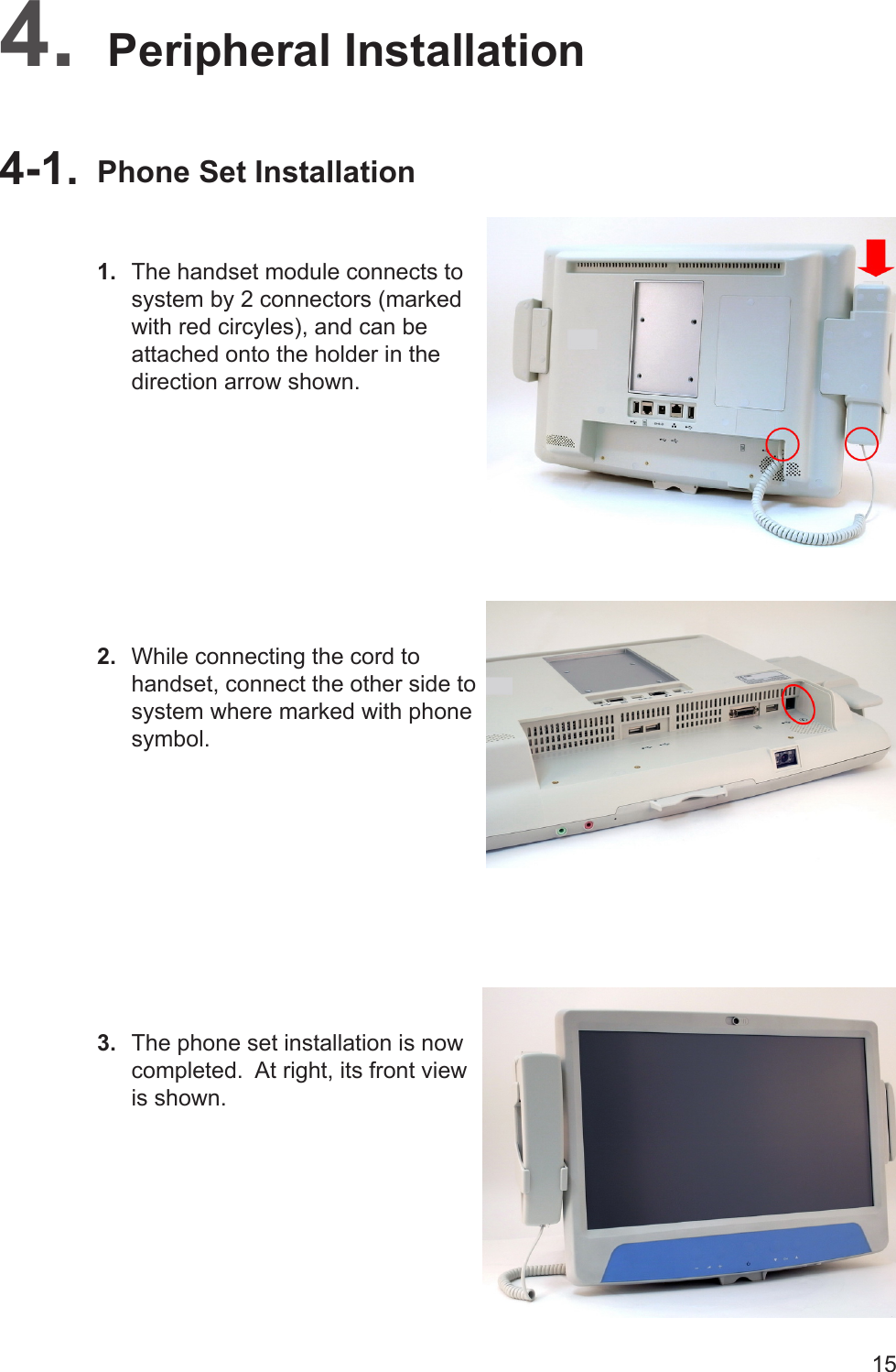
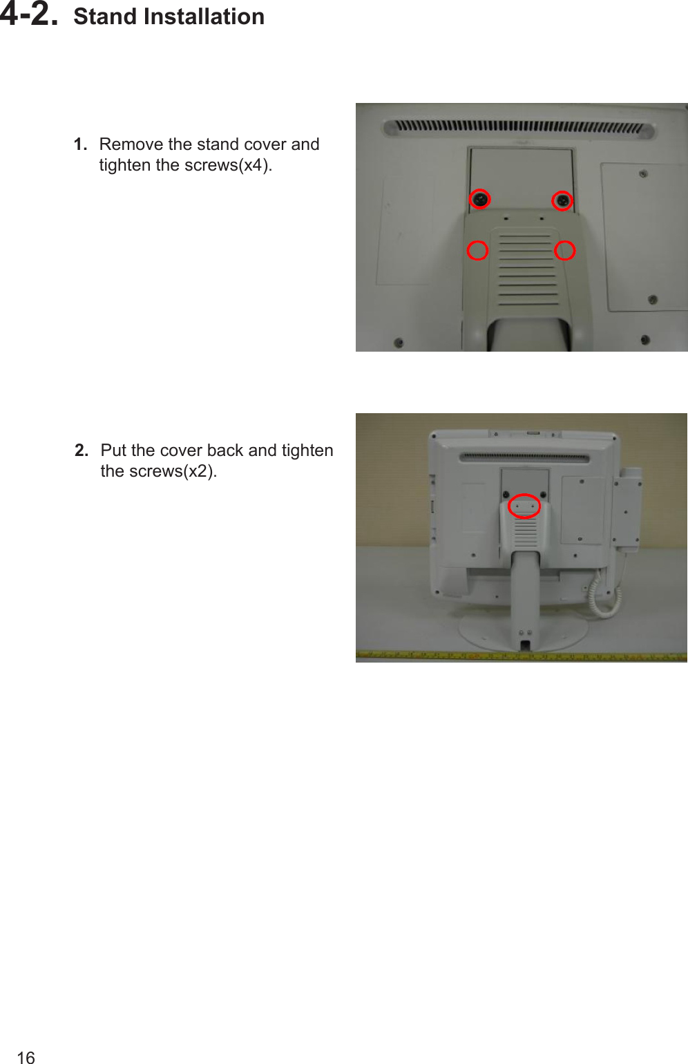
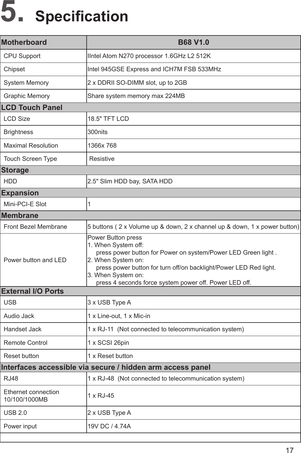
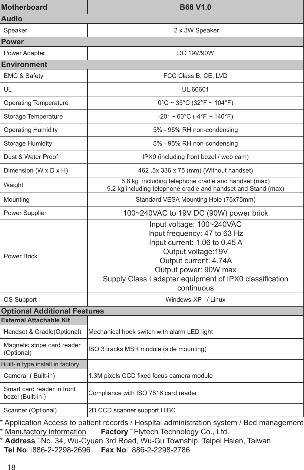
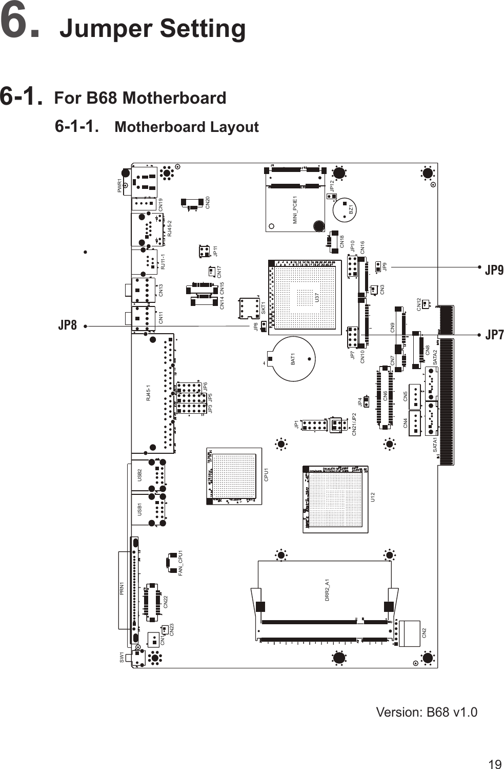
1.
manual1
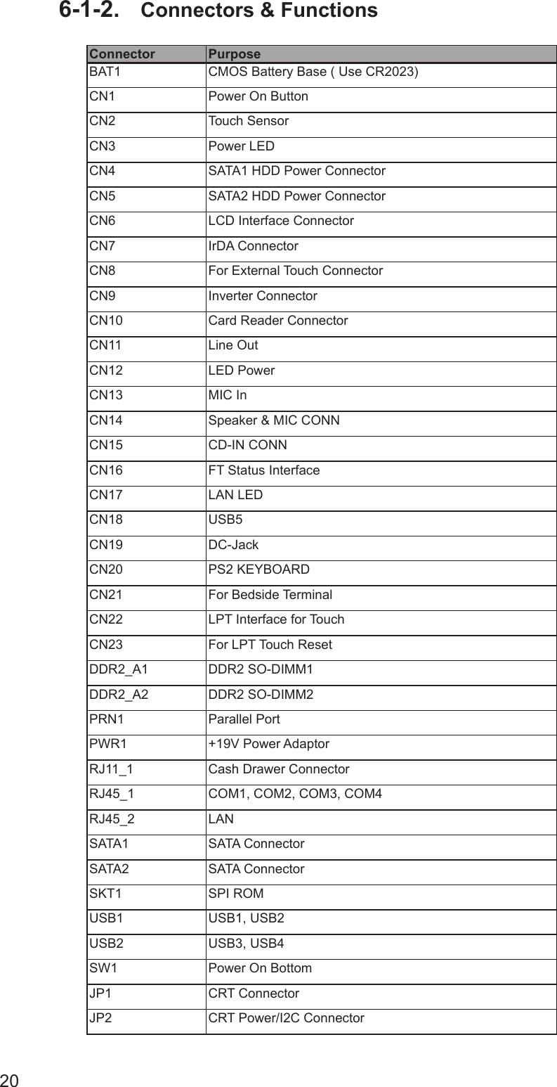
2.
manual2
manual2
Navigation menu
Upload a User Manual
Namespaces
Wiki Guide
HTML
PDF
Info
Views
User Manual
Discussion / Help
Navigation