FLYTECH TECHNOLOGY BED-185 Terminal Hardware System User Manual K938S indb
FLYTECH TECHNOLOGY CO., LTD Terminal Hardware System K938S indb
Contents
- 1. manual1
- 2. manual2
manual2
11
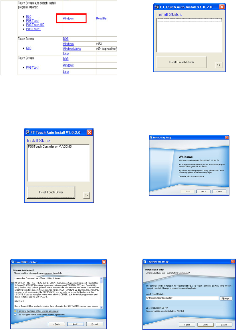
POSTouch Driver Installation
3-6.
a. In the “Touch Screen auto…”
section, click <Windows>.
b. Click <Install Touch Driver>
on “FT Touch Auto Install V1.0.2.0”
window to detect the touch type in
your system.
c. “FT Touch Auto Install”
program will detect what touch type
and interface being installed on the
system.
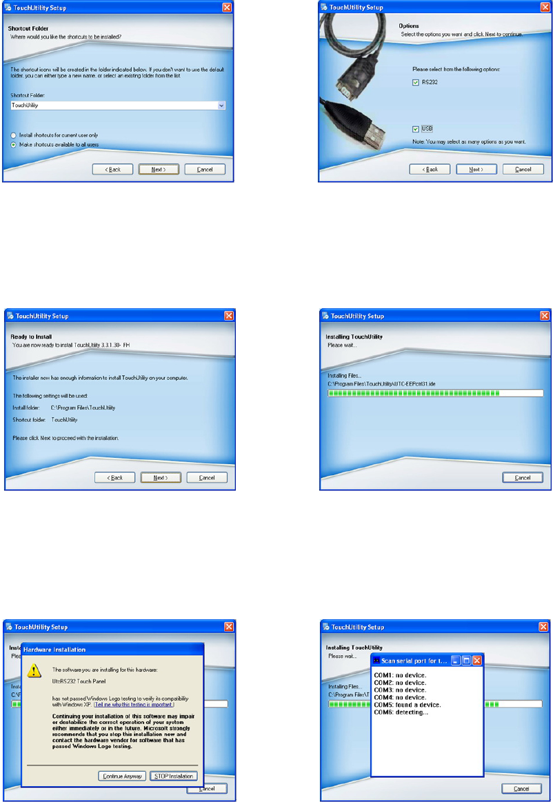
d. Click <Next>.
e. Select ”I agree…” and click
<Next>.
f. Select the installation folder
for the touch utility driver and click
<Next>.
12
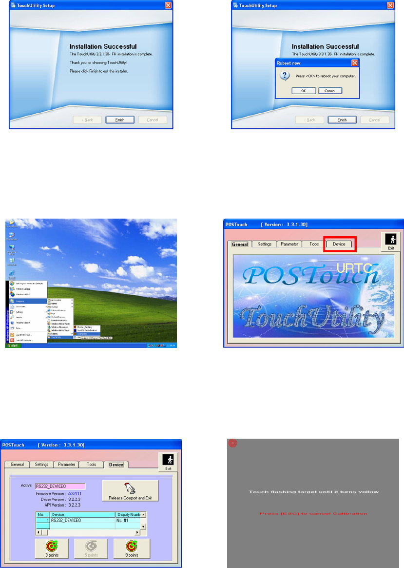
g. Select the shortcut folder
for the touch utility driver and click
<Next>.
h. Click <Next>.
i. Click <Next>. j. The computer is installing the
touch driver
k. Click <Continue Anyway”>
button.
l. The serial ports are scanned
for a touch device. The Touch panel is
on COM5.
13
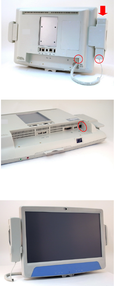
m. Click <Finish>. n. Click <OK> to restart the
computer and finish the touch utility
installation.
o. The computer has restarted.
Click on the <Start> button, select
“Programs”, then select ”Touchutility”.
p. Select the <Device> tab.
q. Click on the 3 points or the 9
points calibration button.
r. Follow the instructions on the
screen to do the calibration of the
touch panel.

14
s. Touch anywhere on the screen to
save the calibration.
15
Peripheral Installation4.
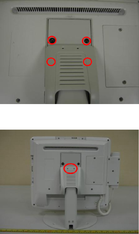
Phone Set Installation
4-1.
The handset module connects to 1.
system by 2 connectors (marked
with red circyles), and can be
attached onto the holder in the
direction arrow shown.
While connecting the cord to 2.
handset, connect the other side to
system where marked with phone
symbol.
The phone set installation is now 3.
completed. At right, its front view
is shown.
16
Stand Installation
4-2.
Remove the stand cover and 1.
tighten the screws(x4).
Put the cover back and tighten 2.
the screws(x2).

17
Motherboard B68 V1.0
CPU Support IIntel Atom N270 processor 1.6GHz L2 512K
Chipset Intel 945GSE Express and ICH7M FSB 533MHz
System Memory 2 x DDRII SO-DIMM slot, up to 2GB
Graphic Memory Share system memory max 224MB
LCD Touch Panel
LCD Size 18.5" TFT LCD
Brightness 300nits
Maximal Resolution 1366x 768
Touch Screen Type Resistive
Storage
HDD 2.5" Slim HDD bay, SATA HDD
Expansion
Mini-PCI-E Slot 1
Membrane
Front Bezel Membrane 5 buttons ( 2 x Volume up & down, 2 x channel up & down, 1 x power button)
Power button and LED
Power Button press
1. When System off:
press power button for Power on system/Power LED Green light .
2. When System on:
press power button for turn off/on backlight/Power LED Red light.
3. When System on:
press 4 seconds force system power off. Power LED off.
External I/O Ports
USB 3 x USB Type A
Audio Jack 1 x Line-out, 1 x Mic-in
Handset Jack 1 x RJ-11 (Not connected to telecommunication system)
Remote Control 1 x SCSI 26pin
Reset button 1 x Reset button
Interfaces accessible via secure / hidden arm access panel
RJ48 1 x RJ-48 (Not connected to telecommunication system)
Ethernet connection
10/100/1000MB 1 x RJ-45
USB 2.0 2 x USB Type A
Power input 19V DC / 4.74A
Specication5.
18
Motherboard B68 V1.0
Audio
Speaker 2 x 3W Speaker
Power
Power Adapter DC 19V/90W
Environment
EMC & Safety FCC Class B, CE, LVD
UL UL 60601
Operating Temperature 0°C ~ 35°C (32°F ~ 104°F)
Storage Temperature -20° ~ 60°C (-4°F ~ 140°F)
Operating Humidity 5% - 95% RH non-condensing
Storage Humidity 5% - 95% RH non-condensing
Dust & Water Proof IPX0 (including front bezel / web cam)
Dimension (W x D x H) 462 .5x 336 x 75 (mm) (Without handset)
Weight 6.8 kg including telephone cradle and handset (max)
9.2 kg including telephone cradle and handset and Stand (max)
Mounting Standard VESA Mounting Hole (75x75mm)
Power Supplier 100~240VAC to 19V DC (90W) power brick
Power Brick
Input voltage: 100~240VAC
Input frequency: 47 to 63 Hz
Input current: 1.06 to 0.45 A
Output voltage:19V
Output current: 4.74A
Output power: 90W max
Supply Class I adapter equipment of IPX0 classication
continuous
OS Support Windows-XP / Linux
Optional Additional Features
External Attachable Kit
Handset & Cradle(Optional) Mechanical hook switch with alarm LED light
Magnetic stripe card reader
(Optional) ISO 3 tracks MSR module (side mounting)
Built-in type install in factory
Camera ( Built-in) 1.3M pixels CCD xed focus camera module
Smart card reader in front
bezel (Built-in ) Compliance with ISO 7816 card reader
Scanner (Optional) 2D CCD scanner support HIBC
* Application Access to patient records / Hospital administration system / Bed management
* Manufactory information Factory:Flytech Technology Co., Ltd.
* Address:No. 34, Wu-Cyuan 3rd Road, Wu-Gu Township, Taipei Hsien, Taiwan
Tel No:886-2-2298-2696 Fax No:886-2-2298-2786
19
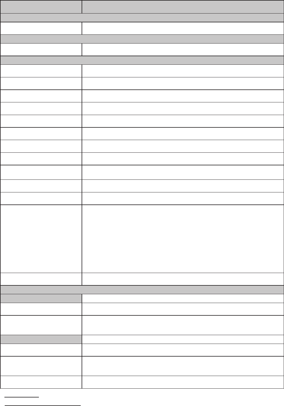
Jumper Setting6.
For B68 Motherboard
6-1.
Motherboard Layout6-1-1.
FAN_CPU1
CN1
CN23
CN22
1NRP1WS
USB1 USB2
RJ45-1
CN11 CN13 RJ11-1
RJ45-2
CN19
CN20
CN15CN14 CN17
PWR1
CPU1
DRR2_A1
U12
CN21/JP2 JP10
JP12
BZ1
MINI_PCIE1
CN16
CN18
CN10
CN6
CN4
CN8
CN12
CN9CN7
CN3
CN5
SATA2SATA1
JP1
CN2
SKT1
U37
BAT1
JP3
JP4
JP9
JP7
JP5
JP6
JP11
JP8
JP7
JP9
JP8
Version: B68 v1.0

20
Connectors & Functions6-1-2.
Connector Purpose
BAT1 CMOS Battery Base ( Use CR2023)
CN1 Power On Button
CN2 Touch Sensor
CN3 Power LED
CN4 SATA1 HDD Power Connector
CN5 SATA2 HDD Power Connector
CN6 LCD Interface Connector
CN7 IrDA Connector
CN8 For External Touch Connector
CN9 Inverter Connector
CN10 Card Reader Connector
CN11 Line Out
CN12 LED Power
CN13 MIC In
CN14 Speaker & MIC CONN
CN15 CD-IN CONN
CN16 FT Status Interface
CN17 LAN LED
CN18 USB5
CN19 DC-Jack
CN20 PS2 KEYBOARD
CN21 For Bedside Terminal
CN22 LPT Interface for Touch
CN23 For LPT Touch Reset
DDR2_A1 DDR2 SO-DIMM1
DDR2_A2 DDR2 SO-DIMM2
PRN1 Parallel Port
PWR1 +19V Power Adaptor
RJ11_1 Cash Drawer Connector
RJ45_1 COM1, COM2, COM3, COM4
RJ45_2 LAN
SATA1 SATA Connector
SATA2 SATA Connector
SKT1 SPI ROM
USB1 USB1, USB2
USB2 USB3, USB4
SW1 Power On Bottom
JP1 CRT Connector
JP2 CRT Power/I2C Connector
21
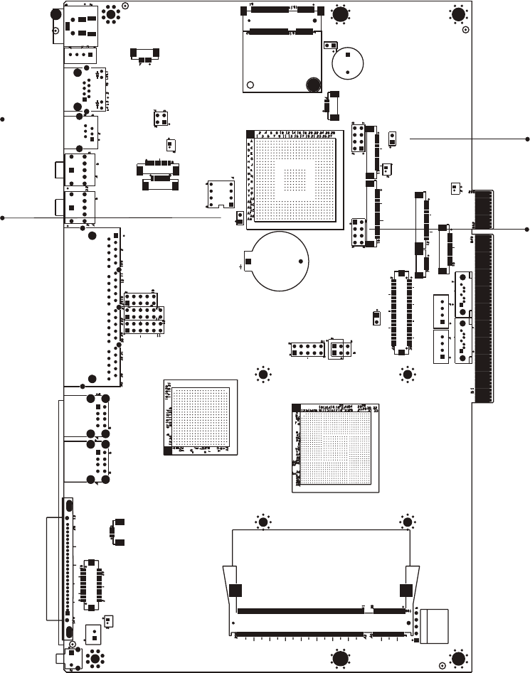
Jumper Setting6-1-3.
Power Mode Setting
Function JP9
▲ATX Power 2
1
AT Power 2
1
RTC Reset
Function JP8
▲CMOS Normal 2
1
CMOS Reset 2
1
▲ = Manufacturer Default Setting
2
1
Jumper open 2
1
Jumper short
22
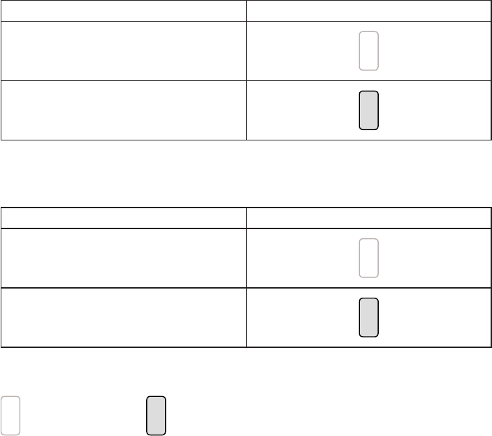
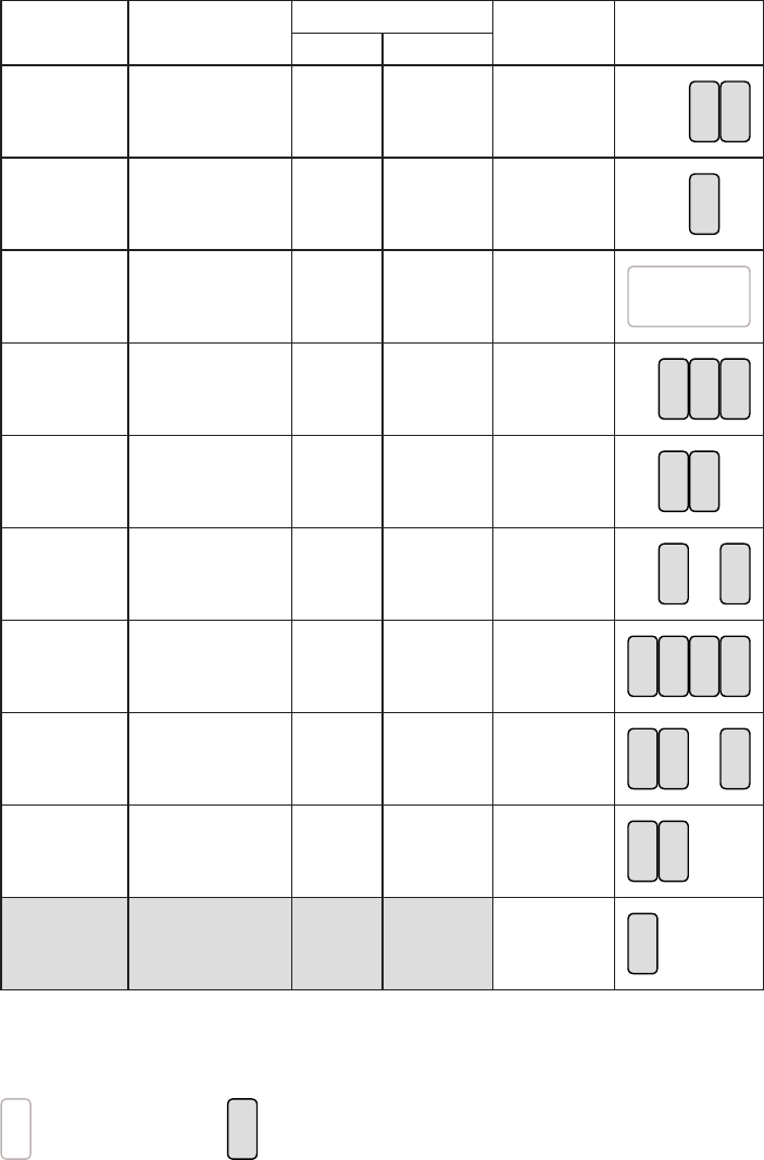
LCD ID Setting
Panel# Resolution LVDS Output
Interface JP7
Bits Channel
1 1366 x 768 24 Single LVDS
Panel 8
5 7
2
1 3
64
2 1440 x 900 24 Dual LVDS
Panel 8
5 7
2
1 3
64
4 1920 x 1080 24 Dual LVDS
Panel 8
5 7
2
1 3
64
5 1024 x 768 24 Single LVDS
Panel 8
5 7
2
1 3
64
6 1280 x 1024 24 Dual LVDS
Panel 8
5 7
2
1 3
64
7 800 x 600 24 Single LVDS
Panel 8
5 7
2
1 3
64
9 1024 x 768 18 Single LVDS
Panel 8
5 7
2
1 3
64
11 800 x 600 18 Single LVDS
Panel 8
5 7
2
1 3
64
12 800 x 600 18 Single LVDS
Panel 8
5 7
2
1 3
64
CRT 8
5 7
2
1 3
64
Remark:
Panel ID#12 is specialized for Sharp 12.1” LQ121S1LG41/LQ121S1LG42 panel
2
1
Jumper open 2
1
Jumper short