Fabmatics LF-134-SER LF RFID device User Manual LF 134 SER
Roth & Rau - Ortner GmbH LF RFID device LF 134 SER
UserManual.wiki
>
Fabmatics
>
LF 134 SER User Manual
UserMan
Navigation menu
Upload a User Manual
Namespaces
Wiki Guide
HTML
PDF
Info
Views
User Manual
Discussion / Help
Navigation
![15 - 62 Revision: 3.5 LF-134-SER-P.M-V3.1 Manual V3.5.docx 5 Service Information 5.1 Contact To buy RFID components or spare parts, please contact our sales team: Phone: +49 351 88861-23 / 31 (only daytime CET) Fax: +49 351 88861-20 mailto: ortner.sales@roth-rau.com To get Support, a RMA No. or the RMA form to place a warranty request for RFID compo-nents, please contact: Roth & Rau - Ortner GmbH, Germany Phone: +49 351 88861-0 (only daytime) Fax: +49 351 88861-20 mailto: ortner.support@roth-rau.com or Roth & Rau - Ortner USA, Inc., Salt Lake City Phone: 801 748 0476 (only daytime) Fax: 801 748 0158 mailto: ortner.info@roth-rau.com 5.2 Return Material Authorization (RMA) Before returning a defective device to Roth & Rau - Ortner, it is necessary to request a RMA number. This process ensures the proper return of the product and enables a faster classifi-cation and repair/replacement of the defective device. You can download the RMA form at www.roth-rau.com/ortner/contact.php?rma=1 Customer contacts Roth & Rau - Ortner and request a RMA number: Phone: +49 351 88861-77 mailto: ortner.support@roth-rau.com Roth & Rau - Ortner generates a RMA number Using the RMA number, the customer completes the RMA form Ship the defective unit with the RMA-Report to: Roth & Rau - Ortner GmbH R M A [ number ] Manfred-von-Ardenne-Ring 7 01099 Dresden GERMANY IMPORTANT! Please prominently display the RMA number on the packaging, to allow us to serve you faster.](https://usermanual.wiki/Fabmatics/LF-134-SER/User-Guide-1641298-Page-15.png)


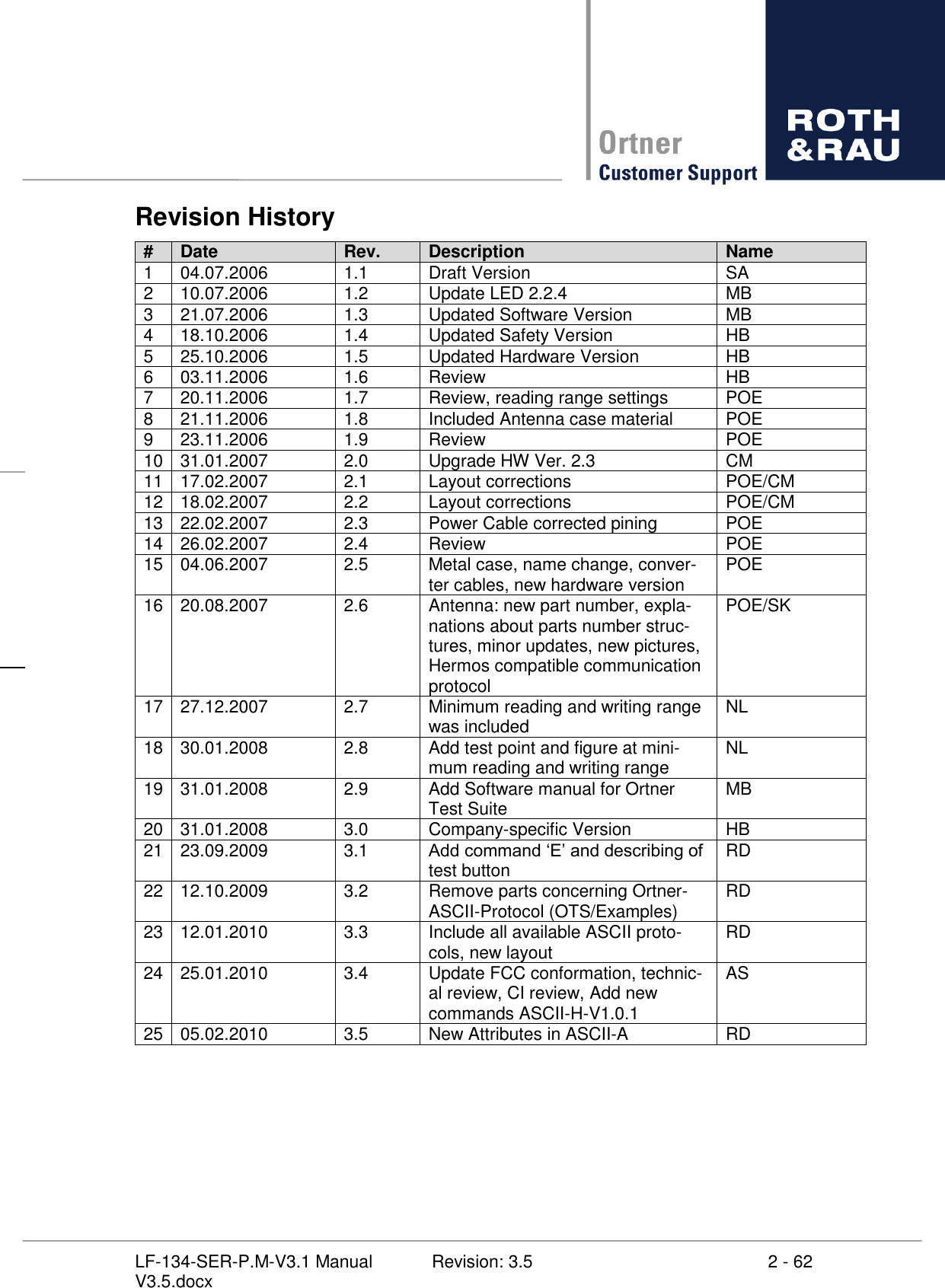
![26 - 62 Revision: 3.5 LF-134-SER-P.M-V3.1 Manual V3.5.docx 7.2 ASCII-L-V2.6.1 protocol description 7.2.1 Communication commands There are only 9 different commands. They are as following: Command Description R Read RO, RW and MPT(Only page 0) transponders W Write RW transponders V Version and Serial number M Read MPT and SAMPT (Only page 0) transponders U Write MPT transponders N Read SAMPT transponders I Write SAMPT transponders L Lock MPT transponders K Lock SAMPT transponders E Returns details for last Error Table 7-2: ASCII-L commands Note: The commands are always upper case. 7.2.2 Command usage 7.2.2.1 Read command n- If a transponder is read it could look like this: READ ONLY READ / WRITE The code looks like this: [startbyte][transponder type][LSB - > MSB8byte][CRCL][CRCH],0x0D,0x0A [LSB - > MSB8byte] is 8 byte of data/serial number 16 ASCII character. [BYTE 0] [BYTE 1] [BYTE 2] [BYTE 3] [BYTE 4] [BYTE 5] [BYTE 6] [BYTE 7] Each byte is made of 2 ASCII characters. Every ASCII character is a HEX value (0 9,A F). Every byte is defined as [high-hex][lowhex] => [BYTE]. The CRC is always calculated. If it is wrong then the LF-134-SER The Reverse CRC is calculated only for Byte 0 7 and is done with the sample routine shown below.](https://usermanual.wiki/Fabmatics/LF-134-SER/User-Guide-1641298-Page-26.png)
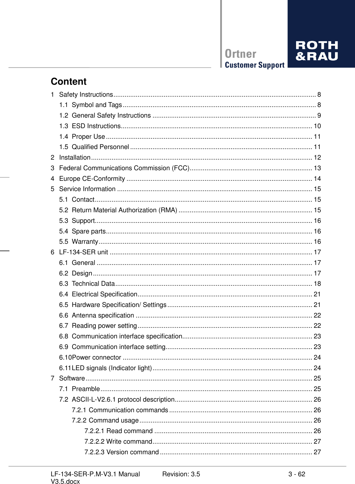
![27 - 62 Revision: 3.5 LF-134-SER-P.M-V3.1 Manual V3.5.docx crc = 0; for (a = 2; a < 10; a++) { rev_crc_ccitt(data_buffer[a],&crc,0x8408); } void rev_crc_ccitt(unsigned int data,unsigned int *accum,unsigned int poly) { unsigned int i; data = data << 1; for (i = 8; i > 0; i--) { data = data >> 1; if ((data ^ *accum) & 0x0001) *accum = (*accum >> 1) ^ poly; else *accum = *accum >> 1; } } 7.2.2.2 Write command characters). It could look like: - > MSB8byte] [LSB - > MSB8byte] is 8 byte of data/serial number 16 ASCII character. [BYTE 0] [BYTE 1] [BYTE 2] [BYTE 3] [BYTE 4] [BYTE 5] [BYTE 6] [BYTE 7] Each byte is made of 2 ASCII characters. Every ASCII character is a HEX value (0 9,A F). Every byte is defined as [high-hex][lowhex] => [BYTE]. 0x45,0x21,0x0D,0x0A. If a transponder is writ READ / WRITE If it is different the write command is not done properly. (Wrong transponder or to far away) 7.2.2.3 Version command The Version command is initiated wit It returns: ](https://usermanual.wiki/Fabmatics/LF-134-SER/User-Guide-1641298-Page-27.png)
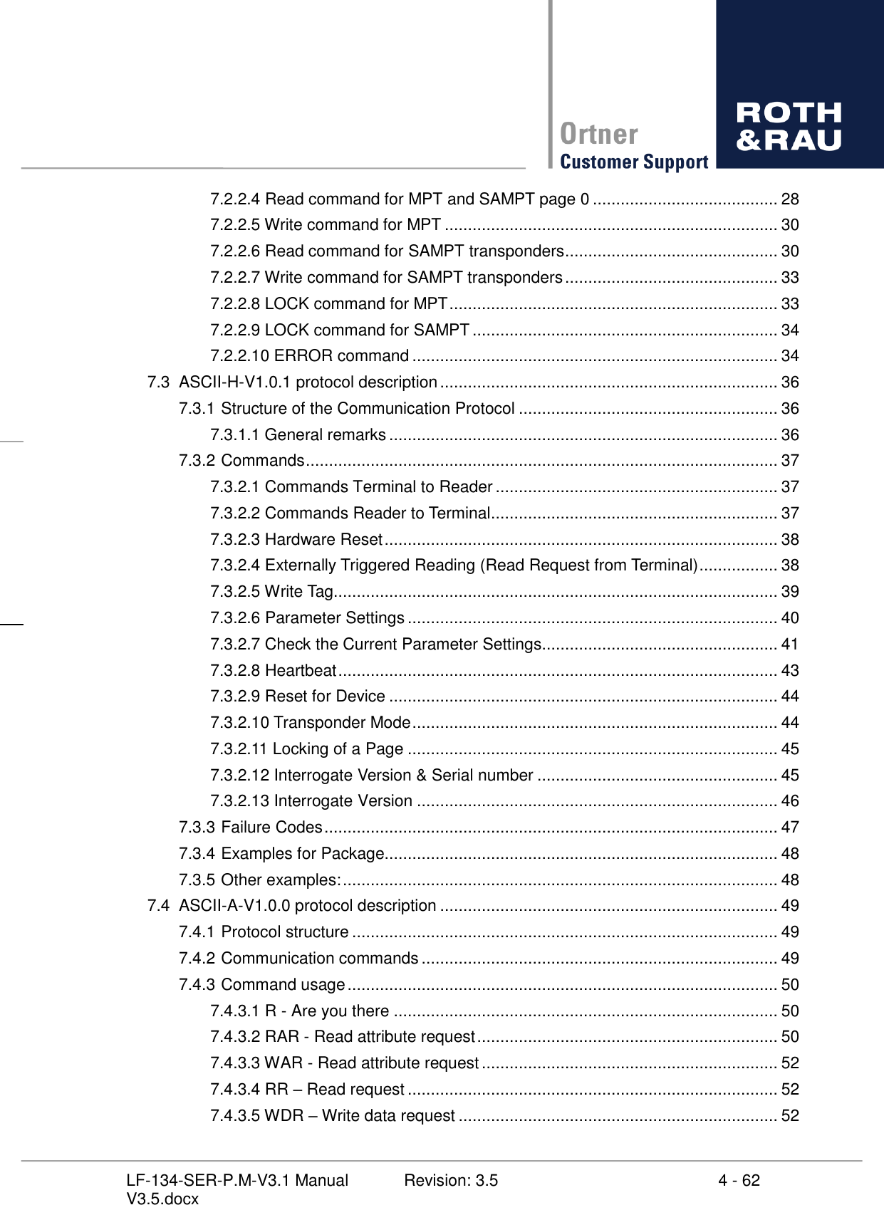
![28 - 62 Revision: 3.5 LF-134-SER-P.M-V3.1 Manual V3.5.docx Try call or email for the right document. 7.2.2.4 Read command for MPT and SAMPT page 0 It could look like: [address] is a single byte of page number 2 ASCII character. The Address goes from 0x01 to 0x11 (page 1 17). [BYTE 0] The byte is made of 2 ASCII characters. Every ASCII character is a HEX value (0 9,A F). Every byte is defined as [high-hex][lowhex] => [BYTE]. 0x45,0x21,0x0D,0x0A. If a transponder is near it will respond with the following code regardless if it is a MPT or SAMPT (Only if page 1 is read): [startbyte][type][LSB - > MSB][DATACRCL][DATACRCH][PAGE][FRAMECRC-L][FRAMECRC-H],0x0D,0x0A [LSB - > MSB] is 8 byte of data/serial number 16 ASCII character. [BYTE 0] [BYTE 1] [BYTE 2] [BYTE 3] [BYTE 4] [BYTE 5] [BYTE 6] [BYTE 7] For the SAMPT transponders, the data field on page 1 contains a 24 bit selective address (Byte 0 2) and 40 bit identification data (Byte 3 7). [DATACRCL][DATACRCH] Data CRC checksum. The CRC is always calculated. If it is wrong then the LF-134-SER modu The Reverse CRC is calculated only for Byte 0 7 and is done with the sample routine be-low. crc = 0; for (a = 2; a < 10; a++) { rev_crc_ccitt(data_buffer[a],&crc,0x8408); }](https://usermanual.wiki/Fabmatics/LF-134-SER/User-Guide-1641298-Page-28.png)
![29 - 62 Revision: 3.5 LF-134-SER-P.M-V3.1 Manual V3.5.docx void rev_crc_ccitt(unsigned int data,unsigned int *accum,unsigned int poly) { unsigned int i; data = data << 1; for (i = 8; i > 0; i--) { data = data >> 1; if ((data ^ *accum) & 0x0001) *accum = (*accum >> 1) ^ poly; else *accum = *accum >> 1; } } [PAGE] contains two status bits and 6 page bits. Bit 0 1 are the status bits. Bit 0 Bit 1 Status 0 0 Read unlocked page 1 0 Programming done 0 1 Read locked page 1 1 Reserved Table 7-3: Status Bits Part 1 of ASCII-L Bit 2 7 is the page bits. BIT 7 2: 00001 Page 1 BIT 7 2: 00010 Page 2 | BIT 7 2: 01000 Page 16 BIT 7 2: 01001 Page 17 If the page bits are zero, programming or locking of page is not done correctly. Then the status bits have the following format: Bit 0 Bit 1 Status 0 0 Read unlocked page, locking not correctly executed 1 0 Programming done, but possible not reliable 0 1 Read locked page, but locking possible not reliable 1 1 Reserved Table 7-4: Status Bits Part 2 of ASCII-L [FRAMECRCL][FRAMECRCH] Frame data CRC checksum. The CRC is always calculated. If it is wrong then the LF-134-SER The Reverse CRC is calculated only for Byte 0 7,datacrc and page info and is done with the sample routine below.](https://usermanual.wiki/Fabmatics/LF-134-SER/User-Guide-1641298-Page-29.png)
![30 - 62 Revision: 3.5 LF-134-SER-P.M-V3.1 Manual V3.5.docx crc = 0; for (a = 2; a < 13; a++) { rev_crc_ccitt(data_buffer[a],&crc,0x8408); } void rev_crc_ccitt(unsigned int data,unsigned int *accum,unsigned int poly) { unsigned int i; data = data << 1; for (i = 8; i > 0; i--) { data = data >> 1; if ((data ^ *accum) & 0x0001) *accum = (*accum >> 1) ^ poly; else *accum = *accum >> 1; } } 7.2.2.5 Write command for MPT (16 ASCII characters). It could look like: 1 byte][LSB - > MSB8byte] [LSB - > MSB8byte] is 8 byte of data/serial number 16 ASCII character. [BYTE 0] [BYTE 1] [BYTE 2] [BYTE 3] [BYTE 4] [BYTE 5] [BYTE 6] [BYTE 7] Each byte is made of 2 ASCII characters. Every ASCII character is a HEX value (0 9,A F). Every byte is defined as [high-hex][lowhex] => [BYTE]. 0x45,0x21,0x0D,0x0A. If a transponder is written it usin READ / WRITE For the format on the data from the LF-134-SER module look on description of the data for-7.2.2.4 Read command for MPT and SAMPT page 0. 7.2.2.6 Read command for SAMPT transponders You need the Selective read address obtained by reading an MPT and SAMPT PAGE 0 by mand as described in chapter 7.2.2.4.](https://usermanual.wiki/Fabmatics/LF-134-SER/User-Guide-1641298-Page-30.png)
![31 - 62 Revision: 3.5 LF-134-SER-P.M-V3.1 Manual V3.5.docx The READ is initiated with an c-ters) and 3 bytes of selective address- It could look like: 3] [address] is a single byte of page number 2 ASCII character. The Address goes from 0x01 to 0x11 (page 1 17). [BYTE 0] [selective address byte 0 3] is a 3 byte selective address obtained by reading page 1 with 6 ASCII character. The Address goes from 0x000000 to 0xFFFFFF. [BYTE 0] [BYTE 1] [BYTE 2] The byte is made of 2 ASCII characters. Every ASCII character is a HEX value (0 9,A F). Every byte is defined as [high-hex][lowhex] => [BYTE]. 0x45,0x21,0x0D,0x0A. If a SAMPT transponder is near it will respond with the following code: [startbyte][type][LSB - > MSB][DATACRCL][DATACRCH][PAGE][FRAMECRC-L][FRAMECRC-H],0x0D,0x0A [LSB - > MSB] is 8 byte of data/serial number 16 ASCII character. [BYTE 0] [BYTE 1] [BYTE 2] [BYTE 3] [BYTE 4] [BYTE 5] [BYTE 6] [BYTE 7] For the SAMPT transponders, the data field on page 1 contains a 24 bit selective address (Byte 0 2) and 40 bit identification data (Byte 3 7). [DATACRCL][DATACRCH] Data CRC checksum. The CRC is always calculated. If it is wrong then the LF-134-SER The Reverse CRC is calculated only for Byte 0 7 and is done with the sample routine be-low. crc = 0; for (a = 2; a < 10; a++) { rev_crc_ccitt(data_buffer[a],&crc,0x8408); }](https://usermanual.wiki/Fabmatics/LF-134-SER/User-Guide-1641298-Page-31.png)
![32 - 62 Revision: 3.5 LF-134-SER-P.M-V3.1 Manual V3.5.docx void rev_crc_ccitt(unsigned int data,unsigned int *accum,unsigned int poly) { unsigned int i; data = data << 1; for (i = 8; i > 0; i--) { data = data >> 1; if ((data ^ *accum) & 0x0001) *accum = (*accum >> 1) ^ poly; else *accum = *accum >> 1; } } [PAGE] contains two status bits and 6 page bits. Bit 0 1 is the status bits. Bit 0 Bit 1 Status 0 0 Read unlocked page 1 0 Programming done 0 1 Read locked page 1 1 Reserved Bit 2 7 is the page bits. BIT 7 2: 00001 Page 1 BIT 7 2: 00010 Page 2 | BIT 7 2: 01000 Page 16 BIT 7 2: 01001 Page 17 If the page bits are zero, programming or locking of page is not done correctly. Then the status bits have the following format: Bit 0 Bit 1 Status 0 0 Read unlocked page, locking not correctly executed 1 0 Programming done, but possible not reliable 0 1 Read locked page, but locking possible not reliable 1 1 Reserved [FRAMECRCL][FRAMECRCH] Frame data CRC checksum. The CRC is always calculated. If it is wrong then the LF-134-SER The Reverse CRC is calculated only for Byte 0 7,datacrc and page info and is done with the sample routine below. crc = 0;](https://usermanual.wiki/Fabmatics/LF-134-SER/User-Guide-1641298-Page-32.png)
![33 - 62 Revision: 3.5 LF-134-SER-P.M-V3.1 Manual V3.5.docx for (a = 2; a < 13; a++) { rev_crc_ccitt(data_buffer[a],&crc,0x8408); } void rev_crc_ccitt(unsigned int data,unsigned int *accum,unsigned int poly) { unsigned int i; data = data << 1; for (i = 8; i > 0; i--) { data = data >> 1; if ((data ^ *accum) & 0x0001) *accum = (*accum >> 1) ^ poly; else *accum = *accum >> 1; } } 7.2.2.7 Write command for SAMPT transponders The WRITE is initiated with an c-tive address and 8 bytes of data (16 ASCII characters). It could look like: 1 byte][selective address LSB - > MSB3byte][LSB - > MSB8byte] [LSB - > MSB8byte] is 8 byte of data/serial number 16 ASCII character. [BYTE 0] [BYTE 1] [BYTE 2] [BYTE 3] [BYTE 4] [BYTE 5] [BYTE 6] [BYTE 7] Each byte is made of 2 ASCII characters. Every ASCII character is a HEX value (0 9,A F). Every byte is defined as [high-hex][lowhex] => [BYTE]. If no transponder is near, CRC is wrong0x45,0x21,0x0D,0x0A. READ / WRITE For the format on the data from the LF-134-SER module look on description of the data for-7.2.2.4 Read command for MPT and SAMPT page 0. 7.2.2.8 LOCK command for MPT The WRITE is initiated with an ](https://usermanual.wiki/Fabmatics/LF-134-SER/User-Guide-1641298-Page-33.png)
![34 - 62 Revision: 3.5 LF-134-SER-P.M-V3.1 Manual V3.5.docx It could look like: 1 byte] Each byte is made of 2 ASCII characters. Every ASCII character is a HEX value (0 9,A F). Every byte is defined as [high-hex][lowhex] => [BYTE]. 0x45,0x21,0x0D,0x0A. For the format on the data from the LF-134-SER module look on description of the data for-mat when reading a MPT in the chapter 7.2.2.4 Read command for MPT and SAMPT page 0. 7.2.2.9 LOCK command for SAMPT c-tive address. It could look like: 1 byte][selective address LSB - > MSB3byte] Each byte is made of 2 ASCII characters. Every ASCII character is a HEX value (0 9,A F). Every byte is defined as [high-hex][lowhex] => [BYTE]. 0x45,0x21,0x0D,0x0A. the data should look like this: For the format on the data from the LF-134-SER module look on description of the data for-7.2.2.4 Read command for MPT and SAMPT page 0. 7.2.2.10 ERROR command If a READ- or WRITE-ERROR command. It returns an ](https://usermanual.wiki/Fabmatics/LF-134-SER/User-Guide-1641298-Page-34.png)
![49 - 62 Revision: 3.5 LF-134-SER-P.M-V3.1 Manual V3.5.docx 7.4 ASCII-A-V1.0.0 protocol description 7.4.1 Protocol structure The protocol structure accords to Asyst ASCII protocol version S: Command: TargetID HCS Command Param1 ... Paramn (CR)(LF)[(CS1)(CS2)] Response: TargetID HCA Response SSACK Param1 ... Paramn (CR)(LF)[(CS1)(CS2)] TargetID Head ID The LF-134-SER accepts TargetIDs from 1 to 31 (like SEMI E99) TargetID in response is always 01 Command multi-character command Params Optional parameters for each command (CR)(LF) Command delimiters (0x0D 0x0A) (CS1)(CS2) Numeric sum including all characters from TargetID to CR/LF CS1 HighByte, CS2 LowByte SSACK Status/error code If EXTENDEDSSACK = OFF 7.4.2 Communication commands Note: Commands are always upper case. Command Description R Are you there RAR Read attribute request WAR Write attribute request RR Read request WDR Write data request RMID Read material ID WMID Write material ID SCR Subsystem command request Table 7-11 ASCII-A commands](https://usermanual.wiki/Fabmatics/LF-134-SER/User-Guide-1641298-Page-49.png)
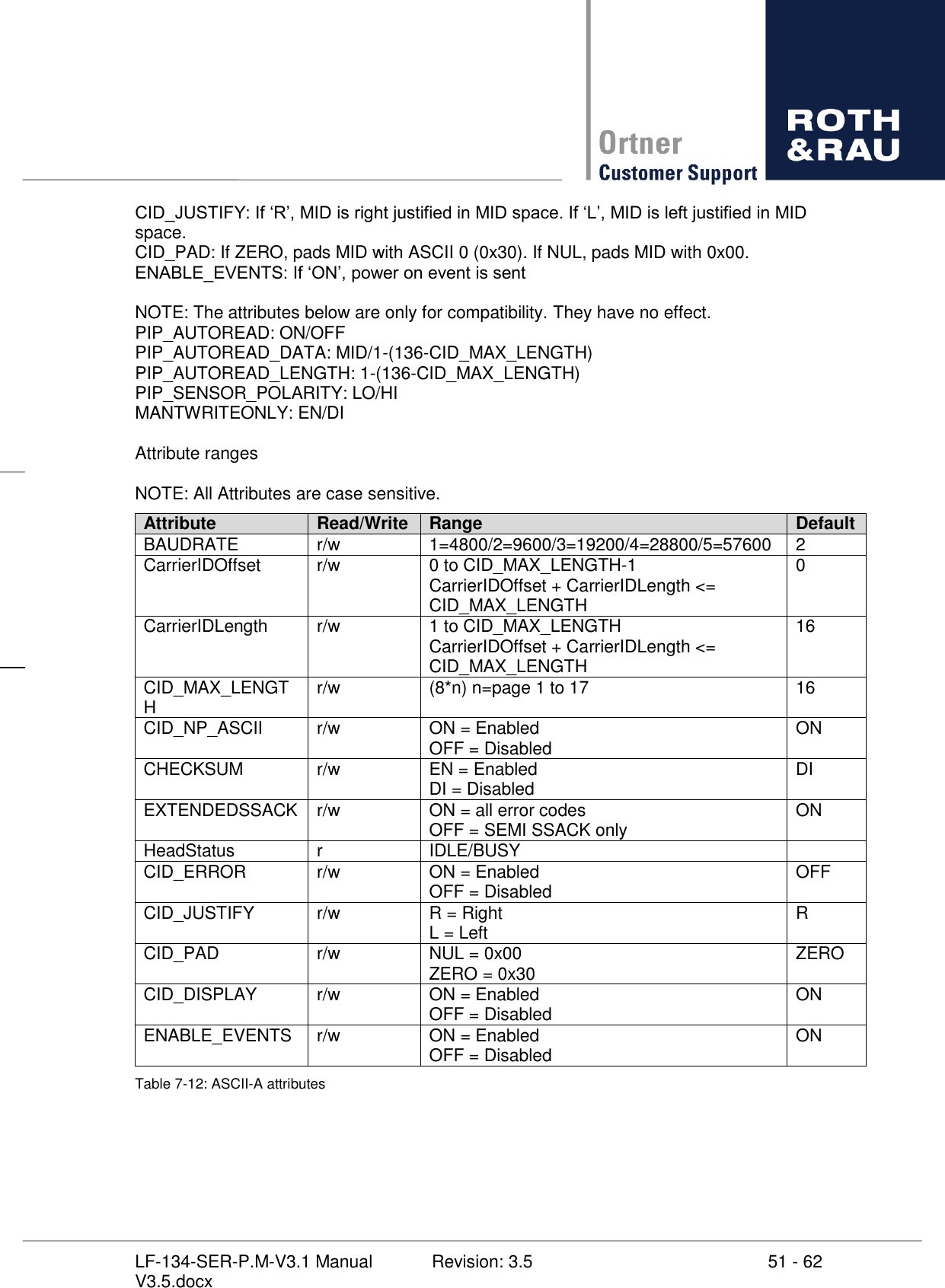
![50 - 62 Revision: 3.5 LF-134-SER-P.M-V3.1 Manual V3.5.docx 7.4.3 Command usage 7.4.3.1 R - Are you there This command is used as heartbeat between host and reader. Example Command: TargetID HCS R(CR/LF) Response: TargetID HCA D NO [HWVERSION] [SWVERSION] 7.4.3.2 RAR - Read attribute request This command requests the current values of head settings. Example Command: TargetID HCS RAR [Paramname1] ... [Paramnamen] Request: TargetID HCA RAD [SSACK] [Paramvalue1] ... [Paramvaluen] Supported Attributes BAUDRATE: Bitrate setting for RS232 CarrierIDOffset: defines start point for reading/writing MID CarrierIDLength: length of MID CID_MAX_LENGTH: max length to read/write MID CID_NP_ASCII: allows / prohibits non printable characters in MID CHECKSUM: enables / disables checksum bytes EXTENDEDSSACK: enables / disables additional error codes. If EXTENDEDSSACK is dis-abled only SEMI SSACK (NO/CE/TE/EE) will be send. - wrong TargetID - invalid offset - invalid length - data too long - data length does not match data - at least one attribute does not exist - at least one attribute out of range - could not write because Tag is locked - subsystem command does not exist - at least one parameter is invalid - invalid checksum - invalid command - invalid command structure HeadStatus: current head status (IDLE / BUSY) CID_ERROR: If ON, results error if MID < CarriedIDLength.](https://usermanual.wiki/Fabmatics/LF-134-SER/User-Guide-1641298-Page-50.png)
![52 - 62 Revision: 3.5 LF-134-SER-P.M-V3.1 Manual V3.5.docx 7.4.3.3 WAR - Read attribute request This command requests the current values of head settings. Example Command: TargetID HCS WAR [Paramname] [Paramvalue] Request: TargetID HCA WADA [SSACK] 7.4.3.4 RR – Read request The RR-command performs a data read from Notepad memory (CID_MAX_LENGTH page 17). Example Command: TargetID HCS RR [Offset] [Length](CR/LF) Offset = startbyte for reading behind CID Length = bytes to read Response: TargetID HCA RDA [SSACK] [DATA] 7.4.3.5 WDR – Write data request This command is used to write data to Notepad memory. It writes data in blocks of 8 bytes. Example Command: TargetID HCS RR [Offset] [Length] [Data](CR/LF) Offset = startbyte for writing behind CID (it has to be match begin of a page e.g. 0 / 8 / 16 ... 112) Length = bytes to write Data = data to write Response: TargetID HCA WDRA [SSACK] Note: This command does not apply to single page or 'read only' transponder! 7.4.3.6 RMID – Read material ID request This command reads the CID using parameter CarrierIDOffset and CarrierIDLength. Example Command: TargetID HCS RMID(CR/LF) Response: TargetID HCA RMIDA [SSACK] [CID]](https://usermanual.wiki/Fabmatics/LF-134-SER/User-Guide-1641298-Page-52.png)
![53 - 62 Revision: 3.5 LF-134-SER-P.M-V3.1 Manual V3.5.docx 7.4.3.7 WMID – Write material ID request This command writes CID to the transponder using parameter CarrierIDOffset and CarrierID-Length. If CID is longer than CarrierIDLength the reader returns an error in SSACK. If CID is shorter than CarrierIDLength CID will padded with '0' or 0x00 in order to CID_PAD and CID_JUSTIFY. Example Command: TargetID HCS WMID [SSACK] [CID](CR/LF) Response: TargetID HCA WMIDA SSACK 7.4.3.8 SCR – Subsystem command request (only reset) Example Command: TargetID HCS SCR Reset (CR/LF) or TargetID HCS SCR 13 (CR/LF) Response: TargetID HCA SCRA NO](https://usermanual.wiki/Fabmatics/LF-134-SER/User-Guide-1641298-Page-53.png)