Fabmatics LF-134-SER LF RFID device User Manual LF 134 SER
Roth & Rau - Ortner GmbH LF RFID device LF 134 SER
UserMan
www.roth-rau.com/ortner
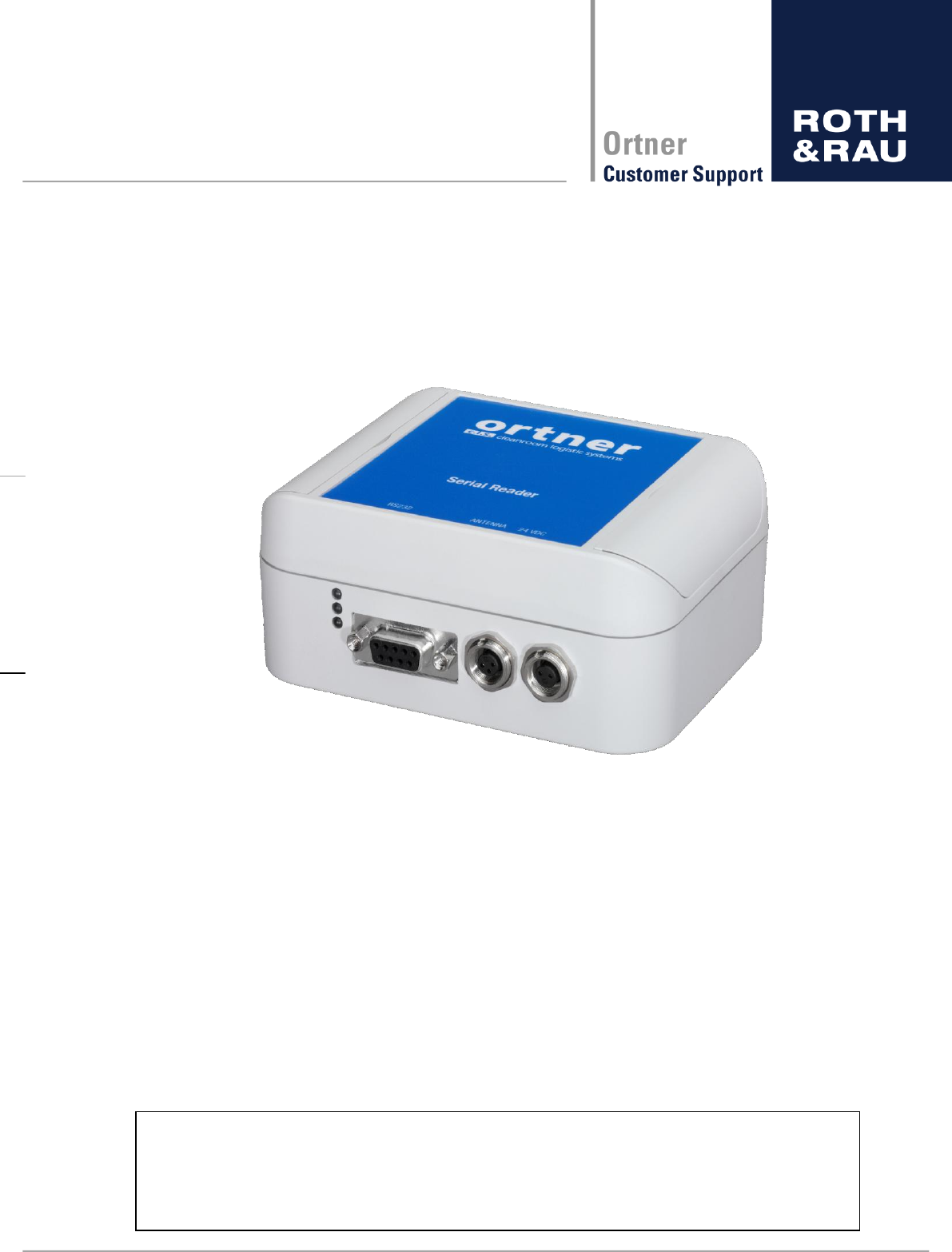
Low Frequency RFID Reader
LF-134-SER-P/M-V3.1
User Manual
Document Revision: 3.5 (all previous versions are inoperative)
Document date: February 26, 2010
This document contains confidential information and has been provided by Roth & Rau - Ortner GmbH for the purpose of
evaluation. No part of this document may be copied, reproduced, disclosed, or transferred by any means without prior
written consent of Roth & Rau - Ortner GmbH. Roth & Rau - Ortner GmbH reserves the right to make updates to the infor-
mation in this document without prior notice or approval from others. Please consult the author of this document to ensure
that you have the latest revision.

2 - 62
Revision: 3.5
LF-134-SER-P.M-V3.1 Manual
V3.5.docx
Revision History
#
Date
Rev.
Description
Name
1
04.07.2006
1.1
Draft Version
SA
2
10.07.2006
1.2
Update LED 2.2.4
MB
3
21.07.2006
1.3
Updated Software Version
MB
4
18.10.2006
1.4
Updated Safety Version
HB
5
25.10.2006
1.5
Updated Hardware Version
HB
6
03.11.2006
1.6
Review
HB
7
20.11.2006
1.7
Review, reading range settings
POE
8
21.11.2006
1.8
Included Antenna case material
POE
9
23.11.2006
1.9
Review
POE
10
31.01.2007
2.0
Upgrade HW Ver. 2.3
CM
11
17.02.2007
2.1
Layout corrections
POE/CM
12
18.02.2007
2.2
Layout corrections
POE/CM
13
22.02.2007
2.3
Power Cable corrected pining
POE
14
26.02.2007
2.4
Review
POE
15
04.06.2007
2.5
Metal case, name change, conver-
ter cables, new hardware version
POE
16
20.08.2007
2.6
Antenna: new part number, expla-
nations about parts number struc-
tures, minor updates, new pictures,
Hermos compatible communication
protocol
POE/SK
17
27.12.2007
2.7
Minimum reading and writing range
was included
NL
18
30.01.2008
2.8
Add test point and figure at mini-
mum reading and writing range
NL
19
31.01.2008
2.9
Add Software manual for Ortner
Test Suite
MB
20
31.01.2008
3.0
Company-specific Version
HB
21
23.09.2009
3.1
test button
RD
22
12.10.2009
3.2
Remove parts concerning Ortner-
ASCII-Protocol (OTS/Examples)
RD
23
12.01.2010
3.3
Include all available ASCII proto-
cols, new layout
RD
24
25.01.2010
3.4
Update FCC conformation, technic-
al review, CI review, Add new
commands ASCII-H-V1.0.1
AS
25
05.02.2010
3.5
New Attributes in ASCII-A
RD

3 - 62
Revision: 3.5
LF-134-SER-P.M-V3.1 Manual
V3.5.docx
Content
1 Safety Instructions ............................................................................................................. 8
1.1 Symbol and Tags ........................................................................................................ 8
1.2 General Safety Instructions ........................................................................................ 9
1.3 ESD Instructions ....................................................................................................... 10
1.4 Proper Use ............................................................................................................... 11
1.5 Qualified Personnel .................................................................................................. 11
2 Installation ....................................................................................................................... 12
3 Federal Communications Commission (FCC) .................................................................. 13
4 Europe CE-Conformity .................................................................................................... 14
5 Service Information ......................................................................................................... 15
5.1 Contact ..................................................................................................................... 15
5.2 Return Material Authorization (RMA) ........................................................................ 15
5.3 Support ..................................................................................................................... 16
5.4 Spare parts ............................................................................................................... 16
5.5 Warranty ................................................................................................................... 16
6 LF-134-SER unit ............................................................................................................. 17
6.1 General .................................................................................................................... 17
6.2 Design ...................................................................................................................... 17
6.3 Technical Data .......................................................................................................... 18
6.4 Electrical Specification .............................................................................................. 21
6.5 Hardware Specification/ Settings .............................................................................. 21
6.6 Antenna specification ............................................................................................... 22
6.7 Reading power setting .............................................................................................. 22
6.8 Communication interface specification...................................................................... 23
6.9 Communication interface setting............................................................................... 23
6.10Power connector ...................................................................................................... 24
6.11 LED signals (Indicator light) ...................................................................................... 24
7 Software .......................................................................................................................... 25
7.1 Preamble .................................................................................................................. 25
7.2 ASCII-L-V2.6.1 protocol description .......................................................................... 26
7.2.1 Communication commands ............................................................................. 26
7.2.2 Command usage ............................................................................................. 26
7.2.2.1 Read command ..................................................................................... 26
7.2.2.2 Write command ...................................................................................... 27
7.2.2.3 Version command .................................................................................. 27

4 - 62
Revision: 3.5
LF-134-SER-P.M-V3.1 Manual
V3.5.docx
7.2.2.4 Read command for MPT and SAMPT page 0 ........................................ 28
7.2.2.5 Write command for MPT ........................................................................ 30
7.2.2.6 Read command for SAMPT transponders .............................................. 30
7.2.2.7 Write command for SAMPT transponders .............................................. 33
7.2.2.8 LOCK command for MPT ....................................................................... 33
7.2.2.9 LOCK command for SAMPT .................................................................. 34
7.2.2.10 ERROR command ............................................................................... 34
7.3 ASCII-H-V1.0.1 protocol description ......................................................................... 36
7.3.1 Structure of the Communication Protocol ........................................................ 36
7.3.1.1 General remarks .................................................................................... 36
7.3.2 Commands ...................................................................................................... 37
7.3.2.1 Commands Terminal to Reader ............................................................. 37
7.3.2.2 Commands Reader to Terminal .............................................................. 37
7.3.2.3 Hardware Reset ..................................................................................... 38
7.3.2.4 Externally Triggered Reading (Read Request from Terminal) ................. 38
7.3.2.5 Write Tag................................................................................................ 39
7.3.2.6 Parameter Settings ................................................................................ 40
7.3.2.7 Check the Current Parameter Settings ................................................... 41
7.3.2.8 Heartbeat ............................................................................................... 43
7.3.2.9 Reset for Device .................................................................................... 44
7.3.2.10 Transponder Mode ............................................................................... 44
7.3.2.11 Locking of a Page ................................................................................ 45
7.3.2.12 Interrogate Version & Serial number .................................................... 45
7.3.2.13 Interrogate Version .............................................................................. 46
7.3.3 Failure Codes .................................................................................................. 47
7.3.4 Examples for Package..................................................................................... 48
7.3.5 Other examples: .............................................................................................. 48
7.4 ASCII-A-V1.0.0 protocol description ......................................................................... 49
7.4.1 Protocol structure ............................................................................................ 49
7.4.2 Communication commands ............................................................................. 49
7.4.3 Command usage ............................................................................................. 50
7.4.3.1 R - Are you there ................................................................................... 50
7.4.3.2 RAR - Read attribute request ................................................................. 50
7.4.3.3 WAR - Read attribute request ................................................................ 52
7.4.3.4 RR Read request ................................................................................ 52
7.4.3.5 WDR Write data request ..................................................................... 52

5 - 62
Revision: 3.5
LF-134-SER-P.M-V3.1 Manual
V3.5.docx
7.4.3.6 RMID Read material ID request .......................................................... 52
7.4.3.7 WMID Write material ID request .......................................................... 53
7.4.3.8 SCR Subsystem command request (only reset) .................................. 53
7.5 Test button ................................................................................................................ 54
8 Antenna ........................................................................................................................... 55
8.1 Technical Specification ............................................................................................. 55
8.2 Drawing .................................................................................................................... 55
8.3 Maximum reading and writing ranges ....................................................................... 56
8.4 Minimum reading and writing range .......................................................................... 58
9 Communication cable ...................................................................................................... 59
9.1 Technical Specification ............................................................................................. 59
9.2 Drawing .................................................................................................................... 59
10 Power cable .................................................................................................................... 60
10.1 Technical Specification .................................................................................... 60
10.2 Drawing ........................................................................................................... 60
11 Parts ordering information ............................................................................................... 61

6 - 62
Revision: 3.5
LF-134-SER-P.M-V3.1 Manual
V3.5.docx
List of Tables
Table 6-1 Technical Data ..................................................................................................... 18
Table 6-2 Electrical Specification ......................................................................................... 21
Table 6-3 Supply Current ..................................................................................................... 21
Table 6-4 Antenna Specification .......................................................................................... 22
Table 6-5 Reading power settings........................................................................................ 22
Table 6-6 Communication interface settings ........................................................................ 23
Table 6-7 Sub D connector .................................................................................................. 23
Table 6-8: Power connector ................................................................................................. 24
Table 6-9: LED signals ......................................................................................................... 24
Table 7-1: Different ASCII versions ...................................................................................... 25
Table 7-2: ASCII-L commands ............................................................................................. 26
Table 7-3: Status Bits Part 1 of ASCII-L ............................................................................... 29
Table 7-4: Status Bits Part 2 of ASCII-L ............................................................................... 29
Table 7-5: ASCII-L Error Codes ........................................................................................... 35
Table 7-6: ASCII-H-V commands ......................................................................................... 37
Table 7-7: ASCII-H responses ............................................................................................. 38
Table 7-8: Hardware reset ASCII-H ..................................................................................... 38
Table 7-9: ASCII-H parameter settings ................................................................................ 41
Table 7-10 ASCII-H failure codes ........................................................................................ 47
Table 7-11 ASCII-A commands ........................................................................................... 49
Table 7-12: ASCII-A attributes ............................................................................................. 51
Table 8-1: Specification of the Antenna................................................................................ 55
Table 9-1: communication cable .......................................................................................... 59
Table 10-1: power cable ...................................................................................................... 60
Table 11-1 parts ordering information .................................................................................. 61

7 - 62
Revision: 3.5
LF-134-SER-P.M-V3.1 Manual
V3.5.docx
Product Revision Status
Old Product Name
New Product Code
Product Re-
vision
Hardware
Version
Available Soft-
ware Versions
Manual
Version
Serial Reader-P
3.0
LF-134-SER-P-V3.0
3.0
(without
Test button)
2.4
ASCII-L-V2.6.1
or
ASCII-H-V1.0.1
or
ASCII-A-V1.0.0
3.5
Serial Reader-M
3.0
LF-134-SER-M-V3.0
Serial Reader-P
3.1
LF-134-SER-P-V3.1
3.1
(with
Test button)
Serial Reader-M
3.1
LF-134-SER-M-V3.1
Our new product code consists of following information:
LF-134-SER-P/M-V3.1
frequency range interface product revision
frequency case version (Plastic or Metal)
Our new software product code consists of the following information:
ASCII-H-V1.0.1
type of communication type of protocol software revision
Version
Description
ASCII-L-V2.6.1
Roth & Rau Ortner developed short command set
(please see section 7.2)
Test button implemented incl. sending error messages to host
ASCII-H-V1.0.1
Command set compatible to Hermos protocol (please see section 7.3)
Test button not implemented
ASCII-A-V1.0.0
Command set compatible to Asyst ASCII CIDRW Version S protocol
(please see section 7.4)
Test button implemented without sending error messages to host
Note: Product revisions are identified by revision numbers. Each revision number corres-
ponds to versions of three components of the product: hardware, software and manual. Each
product revision number is distinctive. The product revision number is assigned accordingly
to distinctive versions of the three components. Version alteration of one of the components
(hardware, software, manual) may alter accordingly the product revision number.
8 - 62
Revision: 3.5
LF-134-SER-P.M-V3.1 Manual
V3.5.docx
1 Safety Instructions
Please recognize the safety regulations. Nevertheless, there are dangers associated with the
use of the equipment even for its intended purpose. You should therefore read the following
safety information carefully and keep it in mind. Only install and operate this equipment if it is
in perfect condition and with reference to this manual. Do not use the equipment if it is dam-
aged.
1.1 Symbol and Tags
Special tags are used in this document to alert technicians to personal and equipment safety
hazards. Before using this document, a thorough understanding of specific safety issues de-
tailed in the Manual must be understood. The following types of safety tags appear in this
document. Note that the following are only examples; they do not indicate a specific hazard
associated with the product.
WARNING
Flammable Material
Flames Risk of fire
DANGER
Electricity; Electrical Hazard
Lightning bolt Dangerous voltage
DANGER
Explosive Material; Explosion Hazard
Object exploding Risk of explosion
WARNING
Non-Ionizing Radiation; Radio Frequency
Abstract radiation transmitter indicates electromagnetic radia-
tion
CAUTION
General Warning
Important instructions

9 - 62
Revision: 3.5
LF-134-SER-P.M-V3.1 Manual
V3.5.docx
1.2 General Safety Instructions
Read and understand all safety and operating instructions before installing and operating the
device.
This instruction is designed for specially trained personnel. This device is NOT intended for
error handling the device shall be carried out by specially trained personnel only.
Keep these instructions. Store this manual in a place that can be accessed at any time by all
persons involved in installing, operating and error handling the device.
Heed all warnings. Follow all warnings on and inside the device and operating instructions.
Install in accordance with the manufacturer's instructions only.
Only use attachments, accessories and connecting cables supplied by the manufacturer.
All error handling except the error handling listed in this manual must be carried out by the
manufacturer.
People with hearing aids should remember that radio signals transmitted by the device might
cause a very unpleasant buzzing noise in their hearing aids.
Do not connect the device to any kind of power supply such as a standard household power
supply. The device should be connected to a power supply of the type described in these
instructions only.
When you disconnect a cable, pull on its conductor and not on the cable itself. Keep the con-
nector evenly aligned to avoid bending any connector pins. When you connect a cable, en-
sure that the connector pins are positioned correctly.
Never over bend the antenna cable or expose it to mechanical loads.
When replacement parts are required, use the replacement parts specified by the manufac-
turer only. Unauthorized substitutions may result in fire, electric shock, or other hazards.
10 - 62
Revision: 3.5
LF-134-SER-P.M-V3.1 Manual
V3.5.docx
All antenna resonant circuit components carry high voltage!
The installer is responsible for installing the device to comply with FCC re-
quirements of human exposure to radio frequency.
To prevent fire, shock hazard, or annoying interference, use recommended
accessories only.
When removing the housing lid, note that the housing lid is connected to the
case with a cable. Remove the lid carefully to prevent damage do not pull it!
Do not operate the device when the housing lid is removed!
Do NOT operate this device without a proper antenna attached. Proper anten-
nas are antennas supplied by the manufacturer and listed in section
Never locate the antenna so that it is very close to or touching parts of the body
while transmitting.
1.3 ESD Instructions
Static electricity can harm electronic components inside the device. All persons who install or
maintain the device must be trained in ESD protection. ESD protection measures must be
observed when opening the device.
Before removing or inserting components, disconnect the power supply.
To prevent electrostatic damage, static electricity must be discharged from the body and
tools before touching components inside the device.
Touch electro sensitive components carefully at their edges only.

11 - 62
Revision: 3.5
LF-134-SER-P.M-V3.1 Manual
V3.5.docx
1.4 Proper Use
This product was developed for reading and writing the TIRIS® transponder only. Any other
use of this device would constitute abuse. All antenna resonant circuit components carry high
voltage! To prevent fire, shock hazard, or annoying interference, use recommended accesso-
ries only. Do not operate the device when the housing is removed! Proper antennas are an-
touching parts of the body while transmitting. This product is designed to be mounted and
operated in an industrial environment as a built-in-device only. It is not designed to be used
as a stand-alone or a portable device in a non-industrial environment, such as a household,
automotive or open-air environment.
1.5 Qualified Personnel
This manual is designed for specially trained personnel only. This device must be installed
and maintained by the manufacturer or its specially trained representatives. Intervention or
error handling not expressively approved in this manual must be carried out by the manufac-
y. If you are unsure about the qualifications that are actually required,
contact the manufacturer.
Unqualified interventions may result in personal injury or damage to the device!
12 - 62
Revision: 3.5
LF-134-SER-P.M-V3.1 Manual
V3.5.docx
2 Installation
This device is designed for use in an indoor industrial environment only. Instal-
lation is only permitted in an environmental indoor climate with a constant tem-
perature of between 0°C and +50°C / 32°F and 122°F, humidity between 25%
and 80%, and a maximum temperature of +50°C / 122°F.
Do not install or use this device in or near water. Never spill liquids of any kind
onto the device. Should spillage occur, unplug the device and let it check from
a technician.
Do not install near heat sources such as radiators, heat registers, stoves, or
other apparatus (including amplifiers) that produce heat. Do not install the de-
vice in a flammable environment.
Never expose the device to intense changes in temperature, otherwise con-
densation can develop inside the device and cause damages.
Do not locate the device near overhead power lines or other electric lights, or
power circuits or where it can encounter such circuits. When installing the de-
vice, take extreme care not to encounter such circuits as they can cause se-
rious injury or death.
The device should not be used in the immediate vicinity of electrical units (such
as medical units, monitors, telephones, televisions and energy-saver lamps),
magnetic data carriers, or metallic objects. This could result in reduced read-
ing/writing ranges.
Never use the device in potentially explosive areas (such as paint shops).
Do not position the device in a location where it can suffer from vibration or
shock.
When the device is installed, the installation location must be adequately illu-
minated.
Do not install the device during periods of lightning.
Ensure the installation location complies with FCC requirements for human
exposure to radio frequency.

13 - 62
Revision: 3.5
LF-134-SER-P.M-V3.1 Manual
V3.5.docx
3 Federal Communications Commission (FCC)
Class A digital device. A digital device that is marketed for use in a commercial, industrial
or business environment, exclusive of a device which is marketed for use by the general pub-
lic or is intended to be used in the home.
Compliance
The product complies with FCC Subpart C Intentional Radiators §15.201 and with Subpart
J Equipment Authorization Procedures § 2.209, when used for its intended purpose. All
emissions are at least 40 dB below the limits in § 15.209 and are verified pursuant to the
procedures in FCC Subpart J of part 2. These limits are designed to provide reasonable pro-
tection against harmful interference when the equipment is operated in a commercial envi-
ronment. This equipment generates, uses, and can radiate radio frequency energy and, if not
installed and used in accordance with the instruction manual, may cause harmful interfe-
rence to radio communications. Operation of this equipment in a residential area is likely to
cause harmful interference in which case the user will be required to correct the interference
at his/her own expense.
Antenna Requirements
The antenna is removable and does not employ a unique connector; however, the device is
professionally installed and maintained. Therefore, the described LF Reader complies with
FCC15.203.
Labeling Requirements
The described LF Reader is not large enough to accommodate a label with the standard
FCC compliance statement. It is therefore provided here as follows:
This device complies with Part 15 of the FCC Rules. Operation is subject to the following two
conditions: (1) this device may not cause harmful interference, and (2) this device must ac-
cept any interference received, including interference that may cause undesired operation.
Changes or modifications not expressly approved by the party responsible for
rity to operate the equipment.

14 - 62
Revision: 3.5
LF-134-SER-P.M-V3.1 Manual
V3.5.docx
4 Europe CE-Conformity
Konformitätserklärung gemäß dem Gesetz über Funkanlagen und Telekommunikations-
endeinrichtungen (FTEG) und der Richtlinie 1999/5/EG (R&TTE)
Declaration of Conformity in accordance with the Radio and Telecommunications Terminal Equipment Act (FTEG)
and Directive 1999/5/EC (R&TTE Directive)
Der Hersteller: Roth & Rau - Ortner GmbH
The manufacturer:
erklärt, dass das Produkt: LF-134-SER-P/M-V3.1
declares, that the product:
Typ: Low Frequency RFID Reader
Type:
bei bestimmungsgemäßer Verwendung den grundlegenden Anforderungen des §3 und den
übrigen einschlägigen Bestimmungen des FTEG entspricht.
complies with the essential requirements of §3 and the other relevant provisions of the FTEG, when used for its
intended purpose.
Relevante Anforderung: Vfg. 39/05
relevant provisions: Allgemeinzuteilung von Frequenzen
im Frequenzbereich 9 - 30 000 kHz
für die Nutzung durch die Allgemeinheit
für induktive Funkanwendungen.
Angewendete harmonisierte Normen: EN 61000-6-4:2001
harmonised standards applied: Elektromagnetische Verträglichkeit Teil 6-4
Fachgrundnorm Störaussendung Industriebe-
reich
EN 61000-6-2:2001
Elektromagnetische Verträglichkeit Teil 6-2
Fachgrundnorm Störfestigkeit Industriebereich

15 - 62
Revision: 3.5
LF-134-SER-P.M-V3.1 Manual
V3.5.docx
5 Service Information
5.1 Contact
To buy RFID components or spare parts, please contact our sales team:
Phone: +49 351 88861-23 / 31 (only daytime CET)
Fax: +49 351 88861-20
mailto: ortner.sales@roth-rau.com
To get Support, a RMA No. or the RMA form to place a warranty request for RFID compo-
nents, please contact:
Roth & Rau - Ortner GmbH, Germany
Phone: +49 351 88861-0 (only daytime)
Fax: +49 351 88861-20
mailto: ortner.support@roth-rau.com
or
Roth & Rau - Ortner USA, Inc., Salt Lake City
Phone: 801 748 0476 (only daytime)
Fax: 801 748 0158
mailto: ortner.info@roth-rau.com
5.2 Return Material Authorization (RMA)
Before returning a defective device to Roth & Rau - Ortner, it is necessary to request a RMA
number. This process ensures the proper return of the product and enables a faster classifi-
cation and repair/replacement of the defective device. You can download the RMA form at
www.roth-rau.com/ortner/contact.php?rma=1
Customer contacts Roth & Rau - Ortner and request a RMA number:
Phone: +49 351 88861-77
mailto: ortner.support@roth-rau.com
Roth & Rau - Ortner generates a RMA number
Using the RMA number, the customer completes the RMA form
Ship the defective unit with the RMA-Report to:
Roth & Rau - Ortner GmbH
R M A [ number ]
Manfred-von-Ardenne-Ring 7
01099 Dresden
GERMANY
IMPORTANT! Please prominently display the RMA number on the packaging,
to allow us to serve you faster.

16 - 62
Revision: 3.5
LF-134-SER-P.M-V3.1 Manual
V3.5.docx
Acknowledgment of receipt and processing of the RMA request by
Roth & Rau - Ortner
Returning the repaired/replaced device
5.3 Support
For all purchased RFID components Roth & Rau Ortner GmbH will provide free phone or
email support. This includes support for the operation of the components and also support for
the integration/installation of components into other equipment. The phone support will be
available at normal working times (8:00 a.m. to 5:00 p.m. CET, outside this timeframe a voice
mail box will be available).
5.4 Spare parts
The components in our current array of products are available as spare parts to our custom-
ers. In case of spare part requests for products which are already removed from our actual
array of products, & Rau Ortner GmbH requires the type information. All components have
an expected product lifetime of 10 years. For this time period we are able to provide spare
parts.
5.5 Warranty
The warranty period is 24 months and begins with the moment of delivery of the device as
proved by an invoice or other documents. The warranty includes the repair of all damages to
the device that occurs within the warranty period and which are evidently caused by faults of
the material or production defects.
The warranty does not include damages caused by incorrect connection, inappropriate han-
dling and non-observance of the technical reports.
17 - 62
Revision: 3.5
LF-134-SER-P.M-V3.1 Manual
V3.5.docx
6 LF-134-SER unit
6.1 General
The LF-134-SER is an RFID module which supports 134.2 kHz half duplex transponders.
--
module contains an RS232 interface.
Features:
RS232 interface
Reads and writes RO/RW/MPT types transponders
Powerful and efficient output stage
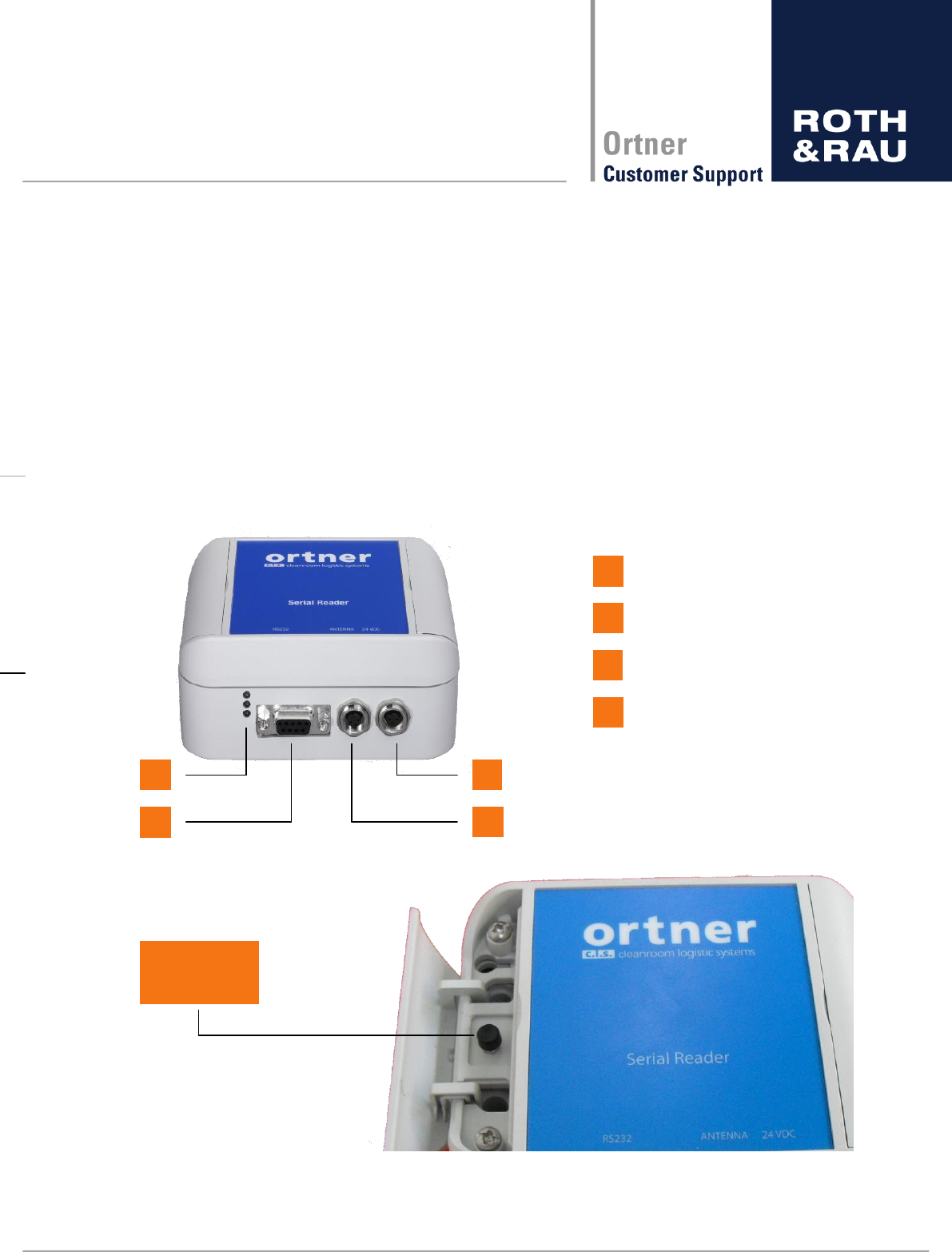
6.2 Design
RS232 Connector
1
2
3
Status LED
Power 24 V DC
2
4
Antenna Connector
3
1
4
Test Button
V3.0 without
V3.1 with

18 - 62
Revision: 3.5
LF-134-SER-P.M-V3.1 Manual
V3.5.docx
6.3 Technical Data
Designation
Version - P
Version - M
Version
LF-134-SER with
plastic case; alumi-
nium-metallized
inside
LF-134-SER with metal
case; particularly suitable for
production environments
with high electromagnetic
interference
Dimensions
120 x 90 x 50mm
97 x 90 x 39mm
(without Base plate)
117 x 90 x 44 mm
(with Base plate)
Weight
235g
255g (without Base plate)
Case:
ABS (Acrylonitrile
butadiene styrene)
Case: tin plate
Base plate: POM
Operating temperature
0°C to +50°C
Storage temperature
-25°C to +50°C
Voltage power supply (typical)
24 V +/- 3%
Power consumption
reading 500mA / stand-by 10mA
Antenna
Ferrite antenna
RFID frequency
134.2kHz
RFID chip
Tiris 134.2kHz HDX/FSK
Readable transponder types
134.2kHz HDX/FSK, MPT, SAMPT, RW, RO
Max. reading range (65 mm antenna)
200mm
MTBF
h
MCBF
Reading time one page
Average 110msec
Table 6-1 Technical Data
19 - 62
Revision: 3.5
LF-134-SER-P.M-V3.1 Manual
V3.5.docx
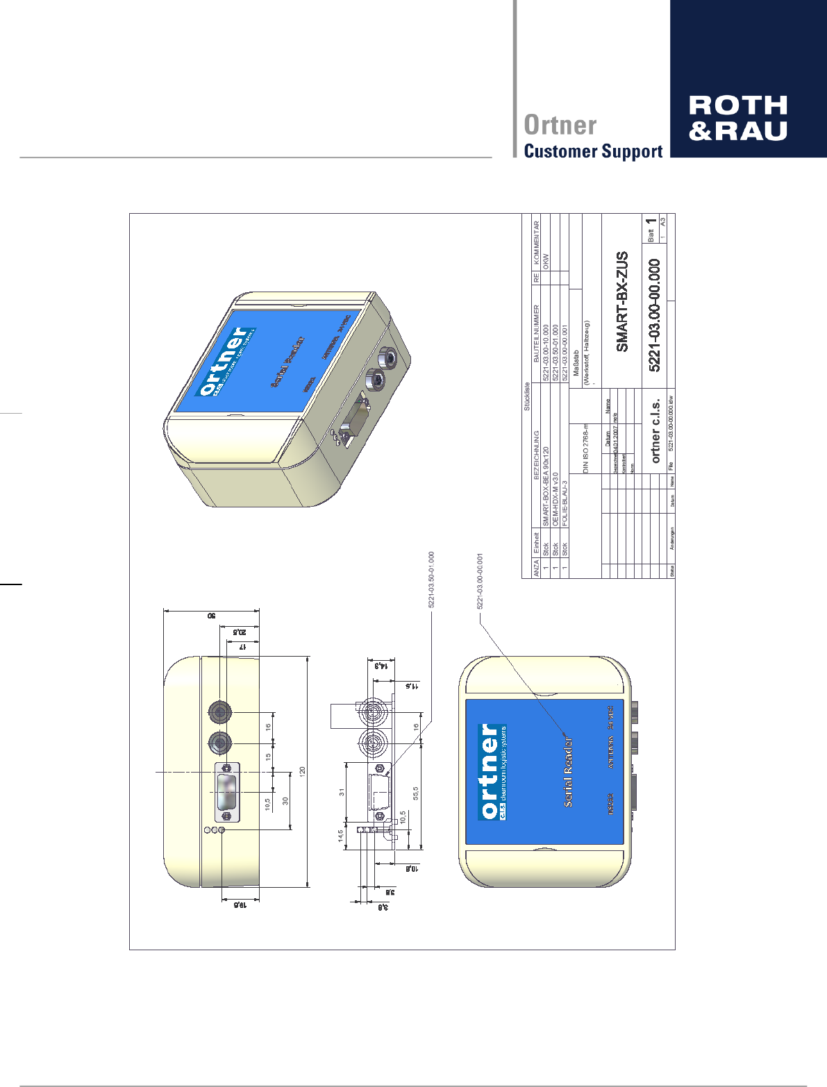
Figure 6-1: Technical Drawing LF-134-SER-P
20 - 62
Revision: 3.5
LF-134-SER-P.M-V3.1 Manual
V3.5.docx
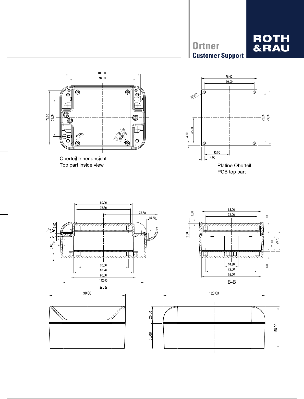
Figure 6-2: Mounting Information LF-134-SER-P
Figure 6-3: Dimensions of LF-134-SER-P
21 - 62
Revision: 3.5
LF-134-SER-P.M-V3.1 Manual
V3.5.docx
6.4 Electrical Specification
Absolute Tolerances
Min
Max
Supply Voltage
21,6 V
26,4 V
Ambient Temperature
0°C
50°C
Table 6-2 Electrical Specification
Supply Current
Supply Voltage = 24V +/- 10%
idle
10 mA
active (1 read / sec)
500 mA
Table 6-3 Supply Current
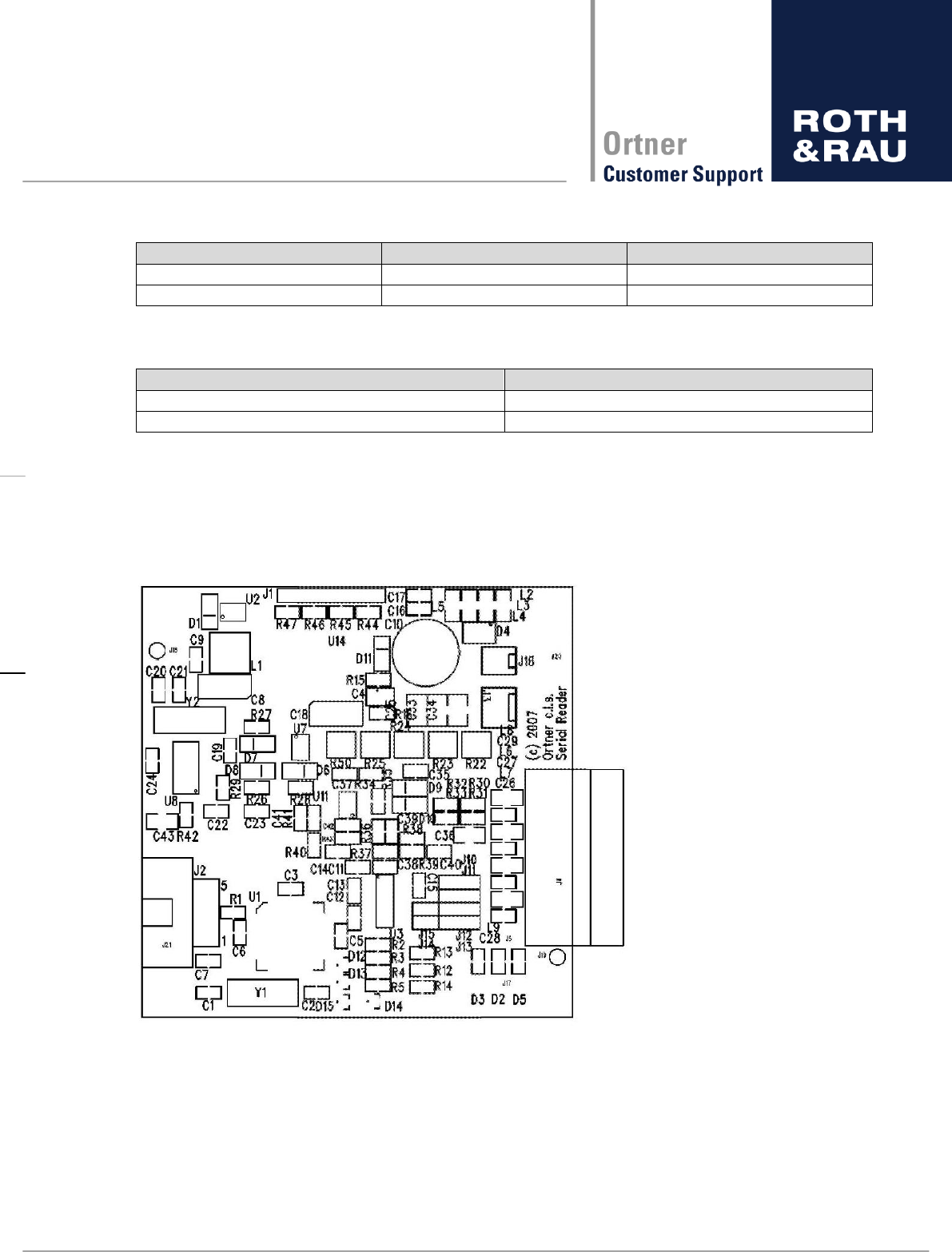
6.5 Hardware Specification/ Settings
The hardware of the LF-134-SER consists of a 4 layer PCB with female DSUB 9 pole con-
nector for communication (J4) and a Binder 3 pin shielded connector for the antenna. The
board is fitted with an ISP connec
Figure 6-4: PCB view of LF-134-SER
22 - 62
Revision: 3.5
LF-134-SER-P.M-V3.1 Manual
V3.5.docx
6.6 Antenna specification
Antenna is connected to J3. Wire thickness should be at least 0.3mm but it can be an air coil
or ferrite coil. 65mm Ferrite coil give >200mm read distance with a 23mm RO TAG.
Antenna specification
Frequency
134 kHz
Inductivity
47 µH+/- 5%
Table 6-4 Antenna Specification
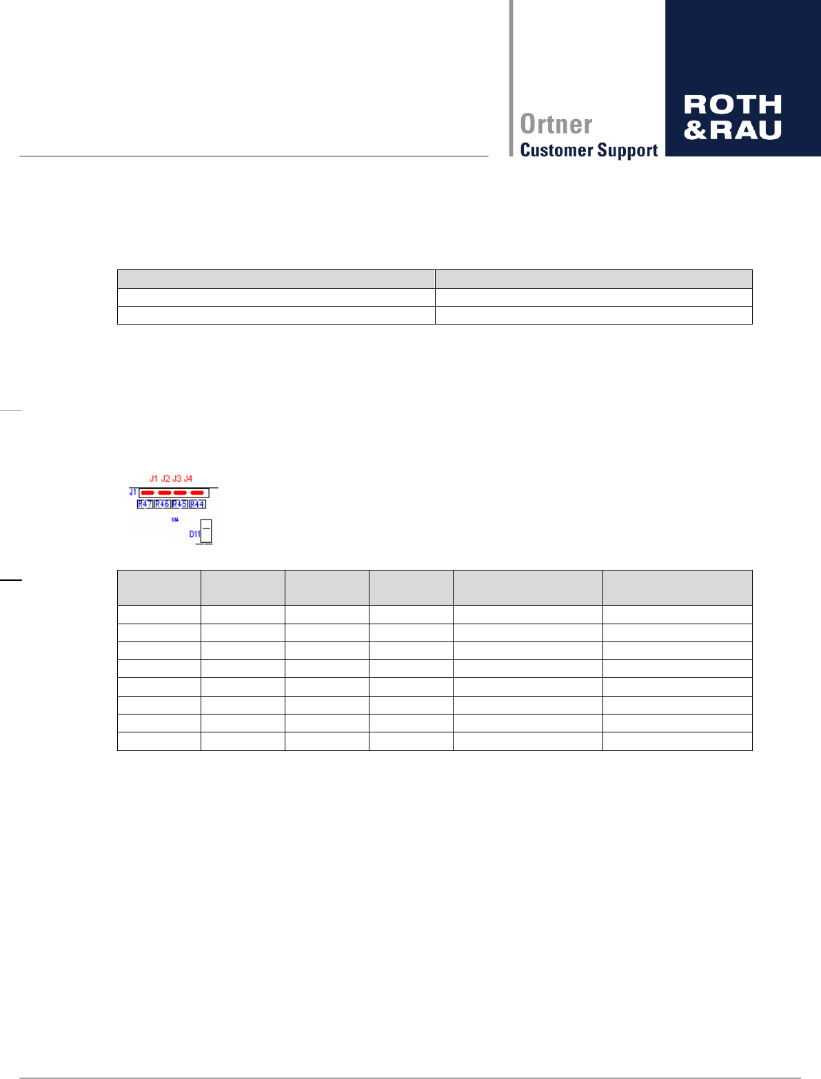
6.7 Reading power setting
Jumper J1 J4 settings for RF power level on LF-134-SER. This setting defines the power
level for the transmitting amplifier. All values are calculated values and might be differ a bit.
J1
J2
J3
J4
RF supply Voltage
(approx.)
Read distance
(approx.)
OFF
OFF
OFF
OFF
23,75 V
100%
OFF
OFF
OFF
ON
14,75 V
85%
ON
OFF
OFF
OFF
12,50 V
81%
ON
OFF
OFF
ON
9,70 V
74%
ON
ON
OFF
OFF
8,75 V
71%
ON
ON
OFF
ON
7,40 V
67%
ON
ON
ON
OFF
6,87 V
66%
ON
ON
ON
ON
6,07 V
63%
Table 6-5 Reading power settings
Without attenuating the output power it is not recommended to read faster than ones per
second. This setting can be adjusted by placing a jumper across pin 7 and 8 on J1 (Selecting
R44). The tags can be read at full speed, which is ~14 times per second with RO types. De-
fault setting is no jumper (full power).
23 - 62
Revision: 3.5
LF-134-SER-P.M-V3.1 Manual
V3.5.docx
6.8 Communication interface specification
The setting of the serial interface depends on the applied software protocol.
Protocol
Bit rate (bit/sec)
Data bits
Stop bits
Parity
ASCII-L-V2.6.1
9600
8
1
none
ASCII-H-V1.0.1
4800/9600/19200/28800/57600
8
1
even
ASCII-A-V1.0.0
4800/9600/19200/28800/57600
8
1
none
Table 6-6 Communication interface settings
J6 – Sub D connector
3
RXD
2
TXD
5
GND
Table 6-7 Sub D connector
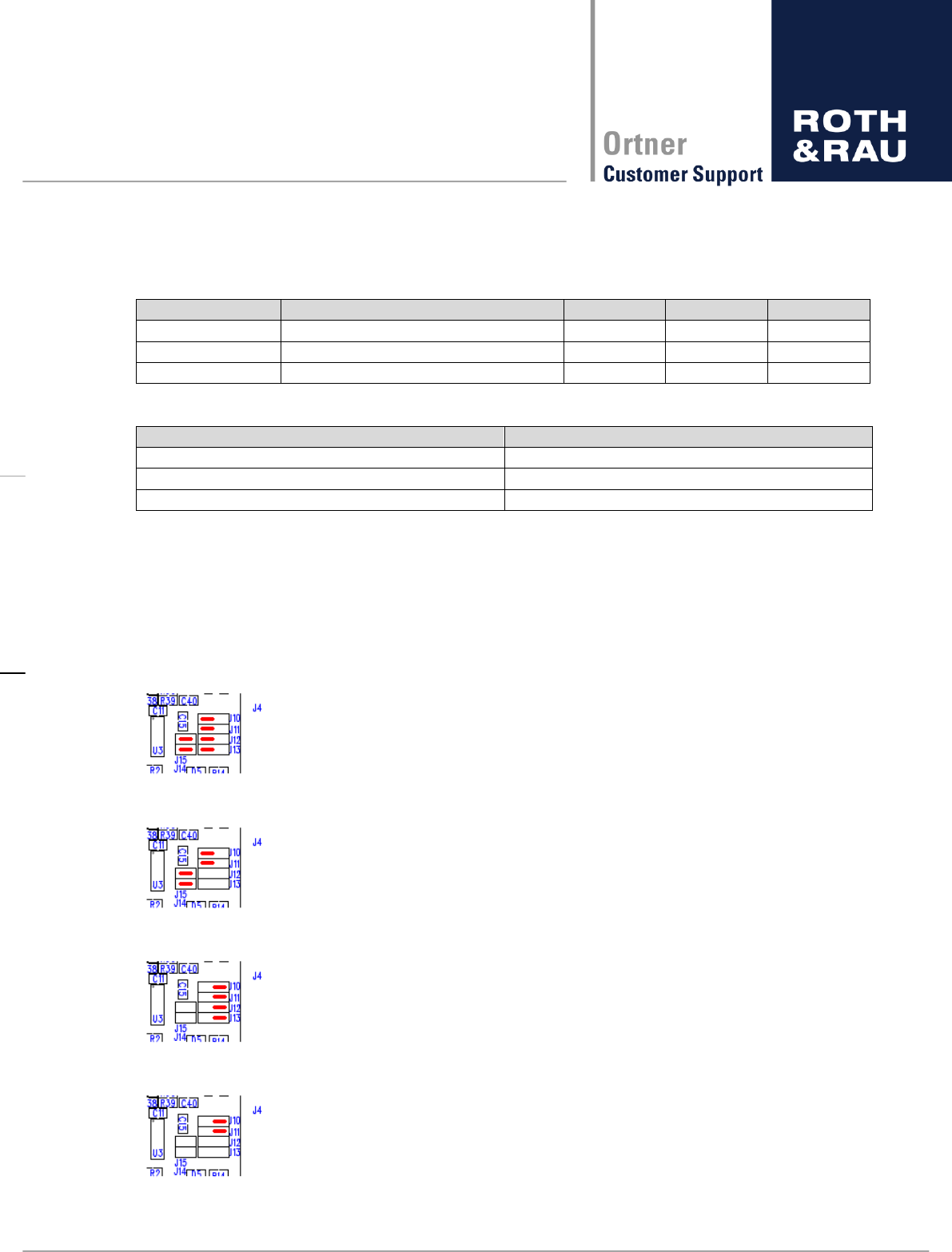
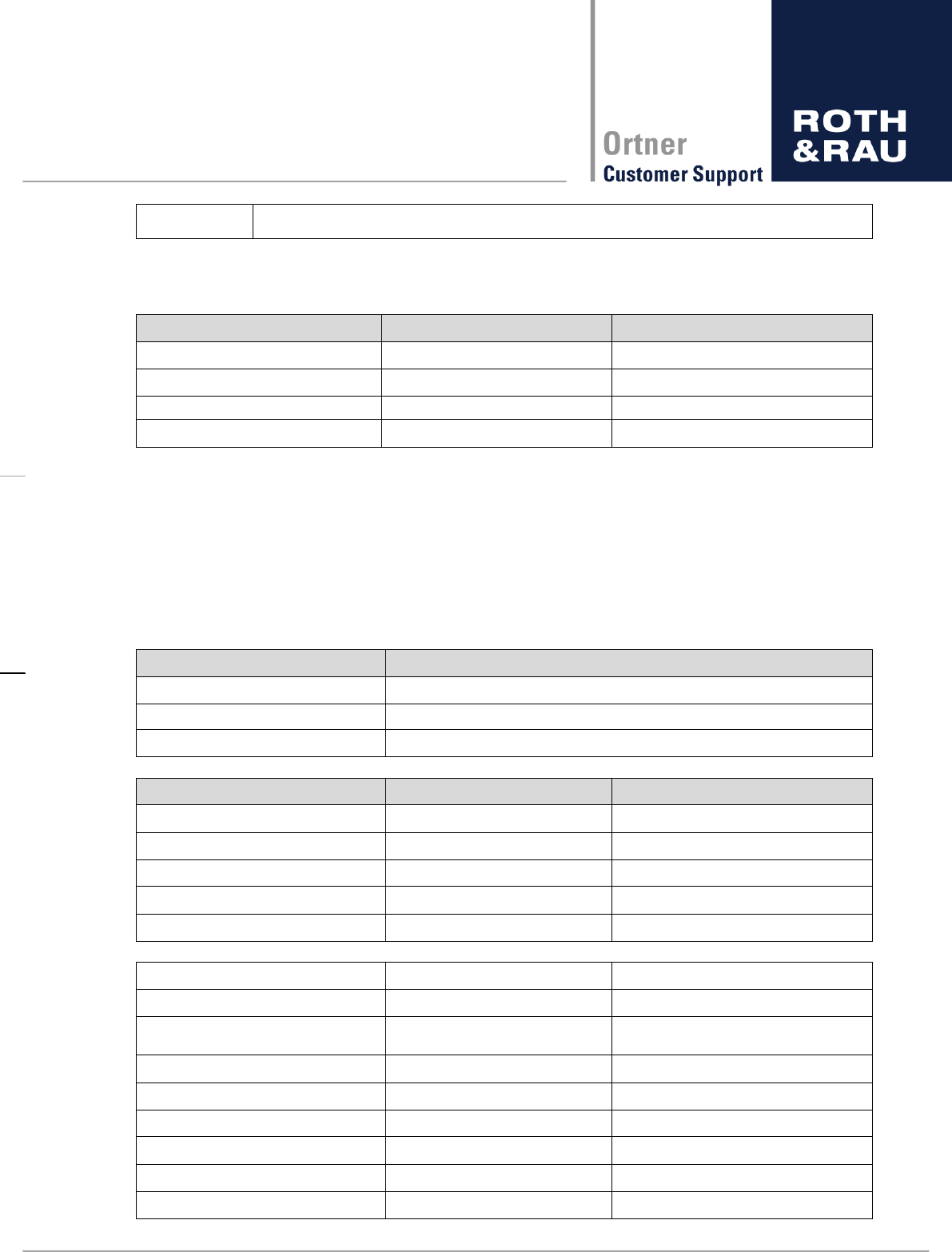
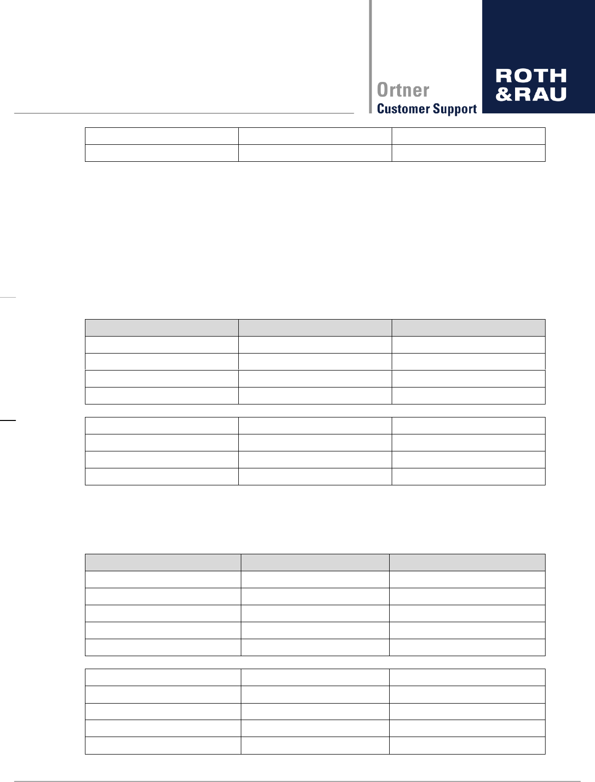
6.9 Communication interface setting
The communication interface supports different operating settings. J10 J 15 can be used to
switch the modes as shown below:
Standard RS 232 with handshake:
Standard RS232 without handshake:
TTL level RS232 with handshake:
TTL level RS 232 without handshake:

24 - 62
Revision: 3.5
LF-134-SER-P.M-V3.1 Manual
V3.5.docx
6.10 Power connector
In table below the Electrical specification is given for connector J3.
J1 – MISC connector
1
24 VDC+/-3%
2
GND
Table 6-8: Power connector
6.11 LED signals (Indicator light)
In the table below the meaning of the LED signals is described
Color
Green
Power/Idle
Yellow
Reading in process (Read success in test mode)
Red
Read error
Table 6-9: LED signals

25 - 62
Revision: 3.5
LF-134-SER-P.M-V3.1 Manual
V3.5.docx
7 Software
7.1 Preamble
The Implementation of our protocols is based on the ASCII communication protocol for RFID
Reader Type Tiris® (Texas Instruments)
We have three different types of ASCII protocols:
Version
Description
ASCII-L-V2.6.1
Roth & Rau Ortner developed short command set
(please see section 7.2)
Test button implemented incl. sending error messages to host
ASCII-H-V1.0.1
Command set compatible to Hermos protocol (please see section 7.3)
Test button not implemented
ASCII-A-V1.0.0
Command set compatible to Asyst ASCII CIDRW Version S protocol
(please see section 7.4)
Test button implemented without sending error messages to host
Table 7-1: Different ASCII versions

26 - 62
Revision: 3.5
LF-134-SER-P.M-V3.1 Manual
V3.5.docx
7.2 ASCII-L-V2.6.1 protocol description
7.2.1 Communication commands
There are only 9 different commands. They are as following:
Command
Description
R
Read RO, RW and MPT(Only page 0) transponders
W
Write RW transponders
V
Version and Serial number
M
Read MPT and SAMPT (Only page 0) transponders
U
Write MPT transponders
N
Read SAMPT transponders
I
Write SAMPT transponders
L
Lock MPT transponders
K
Lock SAMPT transponders
E
Returns details for last Error
Table 7-2: ASCII-L commands
Note: The commands are always upper case.
7.2.2 Command usage
7.2.2.1 Read command
n-
If a transponder is read it could look like this:
READ ONLY
READ / WRITE
The code looks like this:
[startbyte][transponder type][LSB - > MSB8byte][CRCL][CRCH],0x0D,0x0A
[LSB - > MSB8byte] is 8 byte of data/serial number 16 ASCII character.
[BYTE 0] [BYTE 1] [BYTE 2] [BYTE 3] [BYTE 4] [BYTE 5] [BYTE 6] [BYTE 7]
Each byte is made of 2 ASCII characters. Every ASCII character is a HEX value (0 9,A
F). Every byte is defined as [high-hex][lowhex] => [BYTE].
The CRC is always calculated. If it is wrong then the LF-134-SER
The Reverse CRC is calculated only for Byte 0 7 and is done with the sample routine
shown below.

27 - 62
Revision: 3.5
LF-134-SER-P.M-V3.1 Manual
V3.5.docx
crc = 0;
for (a = 2; a < 10; a++)
{
rev_crc_ccitt(data_buffer[a],&crc,0x8408);
}
void rev_crc_ccitt(unsigned int data,unsigned int *accum,unsigned int poly)
{
unsigned int i;
data = data << 1;
for (i = 8; i > 0; i--)
{
data = data >> 1;
if ((data ^ *accum) & 0x0001)
*accum = (*accum >> 1) ^ poly;
else
*accum = *accum >> 1;
}
}
7.2.2.2 Write command
characters).
It could look like:
- > MSB8byte]
[LSB - > MSB8byte] is 8 byte of data/serial number 16 ASCII character.
[BYTE 0] [BYTE 1] [BYTE 2] [BYTE 3] [BYTE 4] [BYTE 5] [BYTE 6] [BYTE 7]
Each byte is made of 2 ASCII characters. Every ASCII character is a HEX value (0 9,A
F). Every byte is defined as [high-hex][lowhex] => [BYTE].
0x45,0x21,0x0D,0x0A.
If a transponder is writ
READ / WRITE
If it is different the write command is not done properly. (Wrong transponder or to far away)
7.2.2.3 Version command
The Version command is initiated wit
It returns:

28 - 62
Revision: 3.5
LF-134-SER-P.M-V3.1 Manual
V3.5.docx
Try call or email for the right document.
7.2.2.4 Read command for MPT and SAMPT page 0
It could look like:
[address] is a single byte of page number 2 ASCII character. The Address goes from 0x01
to 0x11 (page 1 17).
[BYTE 0]
The byte is made of 2 ASCII characters. Every ASCII character is a HEX value (0 9,A F).
Every byte is defined as [high-hex][lowhex] => [BYTE].
0x45,0x21,0x0D,0x0A.
If a transponder is near it will respond with the following code regardless if it is a MPT or
SAMPT (Only if page 1 is read):
[startbyte][type][LSB - > MSB][DATACRCL][DATACRCH][PAGE][FRAMECRC-
L][FRAMECRC-H],0x0D,0x0A
[LSB - > MSB] is 8 byte of data/serial number 16 ASCII character.
[BYTE 0] [BYTE 1] [BYTE 2] [BYTE 3] [BYTE 4] [BYTE 5] [BYTE 6] [BYTE 7]
For the SAMPT transponders, the data field on page 1 contains a 24 bit selective address
(Byte 0 2) and 40 bit identification data (Byte 3 7).
[DATACRCL][DATACRCH] Data CRC checksum.
The CRC is always calculated. If it is wrong then the LF-134-SER modu
The Reverse CRC is calculated only for Byte 0 7 and is done with the sample routine be-
low.
crc = 0;
for (a = 2; a < 10; a++)
{
rev_crc_ccitt(data_buffer[a],&crc,0x8408);
}

29 - 62
Revision: 3.5
LF-134-SER-P.M-V3.1 Manual
V3.5.docx
void rev_crc_ccitt(unsigned int data,unsigned int *accum,unsigned int poly)
{
unsigned int i;
data = data << 1;
for (i = 8; i > 0; i--)
{
data = data >> 1;
if ((data ^ *accum) & 0x0001)
*accum = (*accum >> 1) ^ poly;
else
*accum = *accum >> 1;
}
}
[PAGE] contains two status bits and 6 page bits.
Bit 0 1 are the status bits.
Bit 0
Bit 1
Status
0
0
Read unlocked page
1
0
Programming done
0
1
Read locked page
1
1
Reserved
Table 7-3: Status Bits Part 1 of ASCII-L
Bit 2 7 is the page bits.
BIT 7 2: 00001 Page 1
BIT 7 2: 00010 Page 2
|
BIT 7 2: 01000 Page 16
BIT 7 2: 01001 Page 17
If the page bits are zero, programming or locking of page is not done correctly.
Then the status bits have the following format:
Bit 0
Bit 1
Status
0
0
Read unlocked page, locking not correctly executed
1
0
Programming done, but possible not reliable
0
1
Read locked page, but locking possible not reliable
1
1
Reserved
Table 7-4: Status Bits Part 2 of ASCII-L
[FRAMECRCL][FRAMECRCH] Frame data CRC checksum.
The CRC is always calculated. If it is wrong then the LF-134-SER
The Reverse CRC is calculated only for Byte 0 7,datacrc and page info and is done with
the sample routine below.

30 - 62
Revision: 3.5
LF-134-SER-P.M-V3.1 Manual
V3.5.docx
crc = 0;
for (a = 2; a < 13; a++)
{
rev_crc_ccitt(data_buffer[a],&crc,0x8408);
}
void rev_crc_ccitt(unsigned int data,unsigned int *accum,unsigned int poly)
{
unsigned int i;
data = data << 1;
for (i = 8; i > 0; i--)
{
data = data >> 1;
if ((data ^ *accum) & 0x0001)
*accum = (*accum >> 1) ^ poly;
else
*accum = *accum >> 1;
}
}
7.2.2.5 Write command for MPT
(16 ASCII characters).
It could look like:
1 byte][LSB - > MSB8byte]
[LSB - > MSB8byte] is 8 byte of data/serial number 16 ASCII character.
[BYTE 0] [BYTE 1] [BYTE 2] [BYTE 3] [BYTE 4] [BYTE 5] [BYTE 6] [BYTE 7]
Each byte is made of 2 ASCII characters. Every ASCII character is a HEX value (0 9,A
F). Every byte is defined as [high-hex][lowhex] => [BYTE].
0x45,0x21,0x0D,0x0A.
If a transponder is written it usin
READ / WRITE
For the format on the data from the LF-134-SER module look on description of the data for-
7.2.2.4 Read command for MPT and SAMPT page
0.
7.2.2.6 Read command for SAMPT transponders
You need the Selective read address obtained by reading an MPT and SAMPT PAGE 0 by
mand as described in chapter 7.2.2.4.

31 - 62
Revision: 3.5
LF-134-SER-P.M-V3.1 Manual
V3.5.docx
The READ is initiated with an c-
ters) and 3 bytes of selective address-
It could look like:
3]
[address] is a single byte of page number 2 ASCII character. The Address goes from 0x01
to 0x11 (page 1 17).
[BYTE 0]
[selective address byte 0 3] is a 3 byte selective address obtained by reading page 1 with
6 ASCII character. The Address goes from 0x000000 to 0xFFFFFF.
[BYTE 0] [BYTE 1] [BYTE 2]
The byte is made of 2 ASCII characters. Every ASCII character is a HEX value (0 9,A F).
Every byte is defined as [high-hex][lowhex] => [BYTE].
0x45,0x21,0x0D,0x0A.
If a SAMPT transponder is near it will respond with the following code:
[startbyte][type][LSB - > MSB][DATACRCL][DATACRCH][PAGE][FRAMECRC-
L][FRAMECRC-H],0x0D,0x0A
[LSB - > MSB] is 8 byte of data/serial number 16 ASCII character.
[BYTE 0] [BYTE 1] [BYTE 2] [BYTE 3] [BYTE 4] [BYTE 5] [BYTE 6] [BYTE 7]
For the SAMPT transponders, the data field on page 1 contains a 24 bit selective address
(Byte 0 2) and 40 bit identification data (Byte 3 7).
[DATACRCL][DATACRCH] Data CRC checksum.
The CRC is always calculated. If it is wrong then the LF-134-SER
The Reverse CRC is calculated only for Byte 0 7 and is done with the sample routine be-
low.
crc = 0;
for (a = 2; a < 10; a++)
{
rev_crc_ccitt(data_buffer[a],&crc,0x8408);
}

32 - 62
Revision: 3.5
LF-134-SER-P.M-V3.1 Manual
V3.5.docx
void rev_crc_ccitt(unsigned int data,unsigned int *accum,unsigned int poly)
{
unsigned int i;
data = data << 1;
for (i = 8; i > 0; i--)
{
data = data >> 1;
if ((data ^ *accum) & 0x0001)
*accum = (*accum >> 1) ^ poly;
else
*accum = *accum >> 1;
}
}
[PAGE] contains two status bits and 6 page bits.
Bit 0 1 is the status bits.
Bit 0
Bit 1
Status
0
0
Read unlocked page
1
0
Programming done
0
1
Read locked page
1
1
Reserved
Bit 2 7 is the page bits.
BIT 7 2: 00001 Page 1
BIT 7 2: 00010 Page 2
|
BIT 7 2: 01000 Page 16
BIT 7 2: 01001 Page 17
If the page bits are zero, programming or locking of page is not done correctly.
Then the status bits have the following format:
Bit 0
Bit 1
Status
0
0
Read unlocked page, locking not correctly executed
1
0
Programming done, but possible not reliable
0
1
Read locked page, but locking possible not reliable
1
1
Reserved
[FRAMECRCL][FRAMECRCH] Frame data CRC checksum.
The CRC is always calculated. If it is wrong then the LF-134-SER
The Reverse CRC is calculated only for Byte 0 7,datacrc and page info and is done with
the sample routine below.
crc = 0;

33 - 62
Revision: 3.5
LF-134-SER-P.M-V3.1 Manual
V3.5.docx
for (a = 2; a < 13; a++)
{
rev_crc_ccitt(data_buffer[a],&crc,0x8408);
}
void rev_crc_ccitt(unsigned int data,unsigned int *accum,unsigned int poly)
{
unsigned int i;
data = data << 1;
for (i = 8; i > 0; i--)
{
data = data >> 1;
if ((data ^ *accum) & 0x0001)
*accum = (*accum >> 1) ^ poly;
else
*accum = *accum >> 1;
}
}
7.2.2.7 Write command for SAMPT transponders
The WRITE is initiated with an c-
tive address and 8 bytes of data (16 ASCII characters).
It could look like:
1 byte][selective address LSB - > MSB
3byte][LSB - > MSB8byte]
[LSB - > MSB8byte] is 8 byte of data/serial number 16 ASCII character.
[BYTE 0] [BYTE 1] [BYTE 2] [BYTE 3] [BYTE 4] [BYTE 5] [BYTE 6] [BYTE 7]
Each byte is made of 2 ASCII characters. Every ASCII character is a HEX value (0 9,A
F). Every byte is defined as [high-hex][lowhex] => [BYTE].
If no transponder is near, CRC is wrong
0x45,0x21,0x0D,0x0A.
READ / WRITE
For the format on the data from the LF-134-SER module look on description of the data for-
7.2.2.4 Read command for MPT and SAMPT page
0.
7.2.2.8 LOCK command for MPT
The WRITE is initiated with an

34 - 62
Revision: 3.5
LF-134-SER-P.M-V3.1 Manual
V3.5.docx
It could look like:
1 byte]
Each byte is made of 2 ASCII characters. Every ASCII character is a HEX value (0 9,A
F). Every byte is defined as [high-hex][lowhex] => [BYTE].
0x45,0x21,0x0D,0x0A.
For the format on the data from the LF-134-SER module look on description of the data for-
mat when reading a MPT in the chapter 7.2.2.4 Read command for MPT and SAMPT page
0.
7.2.2.9 LOCK command for SAMPT
c-
tive address.
It could look like:
1 byte][selective address LSB - > MSB3byte]
Each byte is made of 2 ASCII characters. Every ASCII character is a HEX value (0 9,A
F). Every byte is defined as [high-hex][lowhex] => [BYTE].
0x45,0x21,0x0D,0x0A.
the data should look like this:
For the format on the data from the LF-134-SER module look on description of the data for-
7.2.2.4 Read command for MPT and SAMPT page
0.
7.2.2.10 ERROR command
If a READ- or WRITE-
ERROR command. It returns an

35 - 62
Revision: 3.5
LF-134-SER-P.M-V3.1 Manual
V3.5.docx
ERROR CODE
Description
0
No error
1
Read/Write failed
- CRC wrong or
-
2
No transponder found
3
Wrong transponder type
- Read/Write single page as multi page or
- Read/Write multi page (2-17) as single page
4
Write command on locked page
Table 7-5: ASCII-L Error Codes

36 - 62
Revision: 3.5
LF-134-SER-P.M-V3.1 Manual
V3.5.docx
7.3 ASCII-H-V1.0.1 protocol description
7.3.1 Structure of the Communication Protocol
7.3.1.1 General remarks
The communication will be done with ASCII - packages. After each command to the reader a
defined response is sent. It is necessary to wait for this response before sending a new com-
mand.
Package Contents
Each package includes a package header (three signs), a message (two or more signs) and
the end of package (five signs).
package header
Message
end of package
Package Header
The header includes the start sign (one sign) and the package length (two signs).
start
length 1
length 2
start: start sign (ASCII-sign 'S')
length 1: '0'- 'F' high byte package length (hexadecimal) - ASCII-sign
length 2: '0'- 'F' low byte package length (hexadecimal) - ASCII-sign
The message length describes the number of characters of a message.
Message Structure
The message includes a command, a target address and a source address as well as infor-
mation.
command
Address
information
Command: ASCII-sign (refer to the 'Command' chapter)
Address: target/ source address; ASCII sign '0' for ID reader and 'F' for the gateway
Information: depends on the command (includes none, one or more ASCII signs '0'...'F')
End of Package
The end of package includes an end sign (one sign) and a checksum (four signs).
End
Checksum 1
checksum 2
checksum 3
checksum 4
End: end sign ASCII sign no. 13 (hexadecimal 0D)

37 - 62
Revision: 3.5
LF-134-SER-P.M-V3.1 Manual
V3.5.docx
Checksum 1: high byte - XOR logic of all data (package header, message and end
sign);
ASCII '0'...'F'
Checksum 2: low byte - logic of all data (package header, message and end sign);
ASCII '0'...'F'
Checksum 3: high byte - addition of all data (package header, message and end
sign);
ASCII '0'...'F'
Checksum 4: low byte - addition of all data (package header, message and end sign);
ASCII '0'...'F'
7.3.2 Commands
7.3.2.1 Commands Terminal to Reader
Command
Description
start an externally triggered read
'W
write tag
G'
request parameter
'P'
change parameter
'H'
start heartbeat
'N'
start software reset
set/read TransponderMode (single/mpt)
lock one page
version & serial number query
write serial number (require password)
version query
Table 7-6: ASCII-H-V commands
7.3.2.2 Commands Reader to Terminal
Command
Description
'x'
data from a page (externally triggered read)
'w'
response after write to tag
'p'
response during parameter setting
'g'
response to read parameters
'h'
response after heartbeat
'n'
response after software or hardware reset
'e'
failure message
response/ack after TransponderMode-Settings
feedback at locking of one page
response to version & serial number query
38 - 62
Revision: 3.5
LF-134-SER-P.M-V3.1 Manual
V3.5.docx
response to version query
Table 7-7: ASCII-H responses
7.3.2.3 Hardware Reset
Terminal
Direction
Reader
package head
'n'
command
'0'
source address
package end
Table 7-8: Hardware reset ASCII-H
See also section: Reset for Device.
7.3.2.4 Externally Triggered Reading (Read Request from Terminal)
The reading is initiated externally through the command 'X'. The command is configurable
with the following parameters:
Value
Description
'01' to '17'1)
read page #
'98'
read all pages until end sign or empty sign in ID bit 0..3
'99'
read whole tag
Terminal
Direction
Reader
package header
Command
'X'
target address
'0'
value
i.e.'05'
package end
Package Header
'x'
command
'0'
source ad-
dress
page
'0'...'F'
ID bit 60..63
'0'...'F'
ID bit 56..59
'0'...'F'
ID bit 52..55
'0'...'F'
ID bit 48..51
'0'...'F'
ID bit 44..47

39 - 62
Revision: 3.5
LF-134-SER-P.M-V3.1 Manual
V3.5.docx
'0'...'F'
ID bit 40..43
'0'...'F'
ID bit 36..39
'0'...'F'
ID bit 32..35
'0'...'F'
ID bit 28..31
'0'...'F'
ID bit 24..27
'0'...'F'
ID bit 20..23
'0'...'F'
ID bit 16.. 19
'0'...'F'
ID bit 12.. 15
'0'...'F'
ID bit 8..11
'0'...'F'
ID bit 4..7
'0'...'F'
ID bit 0..3
package End
There is no acknowledging from the terminal.
In case of read request for more than one page (value 98 or 99) the protocol will be re-
peated. For the end sign the Reader sends an additional package; the message includes the
command 'x' and the source address '0'). If the reading fails the reading will be repeated
(parameter 3: r/w delay time; parameter 4: r/w maxrepeat). If it fails again the Reader sends
a failure message 'no tag(4)' to the terminal.
1) decimal value
7.3.2.5 Write Tag
The terminal will send the following information to the Reader: target, page and data.
Terminal
Direction
Reader
package header
command
target address
'0'..'E'
page
'01'.. '17' 1)
'0'...'F'
ID bit 60..63
'0'...'F'
ID bit 56..59
'0'...'F'
ID bit 52..55
'0'...'F'
ID bit 48..51
'0'...'F'
ID bit 44..47
'0'...'F'
ID bit 40..43
'0'...'F'
ID bit 36..39
'0'...'F'
ID bit 32..35
'0'...'F'
ID bit 28..31
'0'...'F'
ID bit 24..27
'0'...'F'
ID bit 20..23

40 - 62
Revision: 3.5
LF-134-SER-P.M-V3.1 Manual
V3.5.docx
'0'...'F'
ID bit 16..19
'0'...'F'
ID bit 12..15
'0'...'F'
ID bit 8....11
'0'...'F'
ID bit 4....7
'0'...'F'
ID bit 0....3
package end
package header
'w'
command
'0'..'E'
source ad-
dress
package end
If 'write tag' fails writing will be repeated in the defined time frame (parameter 3: r/w delay
time; parameter 4: r/w maxrepeat). If it fails again, but Transponder is in range, the Reader
sends a failure message 'write fail (3)' to the terminal. If there is no transponder in
1) Decimal value.
7.3.2.6 Parameter Settings
The following reader parameters can be changed:
Parameter
#
Name
Description
Valid Values
0
Sensor delay
operation delay for the
presence sensor
'00'.. '99' (0.1s)
1
readmode
automatic readmode
'00' only one page read '01' read to
end sign or empty sign'02' all pag-
es'10' read only one page check
check sensor first '12' all pages
check sensor first
2
readpage
page for readmode '00'
'01'.. '17'
3
r/w repeattime
time between two read-
ings or writings
'00'.. '99' (0.1s)
4
r/w maxrepeat
max. number of tries to
read or write
'00'.. '99'
5
RS232 repeat-
time
waiting period1) for a
confirmation; if no con-
firmation has been re-
ceived, the message
will be repeated (see
RS232 maxrepeat)
'01.. '99' (0.1s)
6
RS232 ma-
xrepeat
max. numbers of tries
to send data to the
terminal (RS232)
'00' (never ending)
'01' '99'

41 - 62
Revision: 3.5
LF-134-SER-P.M-V3.1 Manual
V3.5.docx
7
watchport
message to the termin-
al that the carrier has
been rejected from I/O
'00' not activated
'01' activated
8
Baudrate
Bitrate for serial inter-
face
(will be resumed after
reset!)
'01' 4800
'02' 9600
'03' 19200
'04' 28800
'05' 57600
9
Parity
Parity bit for serial in-
terface
(will be resumed after
reset!)
'00' none
'01' even
'02' odd
Table 7-9: ASCII-H parameter settings
Terminal
Direction
Reader
package header
command
'P'
target address
'0'..'5'
parameter*
'0'..'7'
value
'00'..'99'
package end
package header
'p'
command
'0'
source ad-
dress
package end
1)
during the waiting period no new actions (for example reading or writing) can be started
Note:
Only parameter 3 (r/w repeattime) & 4 (r/w maxrepeat) takes effect on reader. All other pa-
rameters are only for compatibility.
Parameter 7 (watchport) always co
7.3.2.7 Check the Current Parameter Settings
Terminal
Direction
Reader
package header
command
target address
'0'
package end
package header

42 - 62
Revision: 3.5
LF-134-SER-P.M-V3.1 Manual
V3.5.docx
'g'
command
'0'
source ad-
dress
'0'
value number
'01'.. '99'
value
package end
package header
'g'
command
'0'
source ad-
dress
' 1'
value number
'00'.. '02'
value
package end
package header
'g'
command
'0'
source ad-
dress
'2'
value number
'01'.. '17'
value
package end
package header
'g'
command
'0'
source ad-
dress
'3'
value number
'00'.. '99'
value
package end
package header
'g'
command
'0'
source ad-
dress
'5'
value number
'00'.. '99'
value
package end
package header
'g'
command

43 - 62
Revision: 3.5
LF-134-SER-P.M-V3.1 Manual
V3.5.docx
'0'
source ad-
dress
'5'
value number
'01'.. '99'
value
package end
package header
'g'
command
'0'
source ad-
dress
'6'
value number
'00'.. '99'
value
package end
package header
'g'
command
'0'
source ad-
dress
'7'
value number
'00'.. '01'
value
package end
Package header
'g' 1)
command
'0'
source ad-
dress
Package end
end package includes the command 'g' and the source address
7.3.2.8 Heartbeat
This command is used to check the connection between the terminal and the ID reader.
Terminal
Direction
Reader
package header
command 'H'
target address '0' 1)
package end
package header
'h'
command
'F'
source ad-
dress
'0000'...'FFFF'
reader
ID
44 - 62
Revision: 3.5
LF-134-SER-P.M-V3.1 Manual
V3.5.docx
'0000'
return code
package end
Meaning of the reader ID:
Every reader has a unique 16 bit reader ID after installation.
Every ID may only be used once.
1) Because of compatibility to separated systems the heartbeat is also allowed with the ad-
7.3.2.9 Reset for Device
This command can be used to reset the ID reader (device '0').
During the software reset the reader additionally initiates a self-test.
Terminal
Direction
Reader
package header
command
'N'
target address
'0'
package end
package header
'n'
command
'0'
source ad-
dress
package end
7.3.2.10 Transponder Mode
This command is used to request actual mode or switch between single and multipage-
Terminal
Direction
Reader
package header
command
target address
'0'
mode
package end
package header
'm'
command
'F'
source ad-
dress
mode 1)
package end

45 - 62
Revision: 3.5
LF-134-SER-P.M-V3.1 Manual
V3.5.docx
To request the current settings, the Reader needs Command without new mode-settings
(see examples). If new mode is given, the Reader only sends acknowledge without current
settings.
available modes:
0 - SinglePage-Transponder
1 - MultiPage-Transponder
Note: The Transponder-l-
ways read in SinglePage-Mode.
7.3.2.11 Locking of a Page
The terminal hands over the Reader its address and the page number which shall be locked.
Terminal
Direction
Reader
package header
Command 'L'
target address '0'
package end
Package Header
'l'
command
'0'
source ad-
dress
Package End
If 'write tag' fails writing will be repeated in the defined time frame (parameter 3: r/w delay
time; parameter 4: r/w maxrepeat). If it fails again the Reader sends a failure message
Note: Locking is only possible on a MultiPage-Transponder !
7.3.2.12 Interrogate Version & Serial number
With this function the Version & Serial Number of the reader can be queried. The Version
consists of 8 sign, the Serial consists of 20 sign. As delimiter there is a
The Data is sending in ClearType-ASCII !
Terminal
Direction
Reader
package header
Command 'I'
target address 'F'
package end
Package Header
46 - 62
Revision: 3.5
LF-134-SER-P.M-V3.1 Manual
V3.5.docx
'i'
command
'F'
source ad-
dress
ASCII(8)
8 sign version
ASCII(5)
5 sign delimiter
ASCII(20)
20 sign serial
Package End
Example: S23iFASC0.9.9,S/N:ORT30179.40F8
7.3.2.13 Interrogate Version
With this function the Version-Number can be queried. The Version-Number consists of 8
signs which are stored in ASCII-code.
Terminal
Direction
Reader
package header
Command 'V'
target address
package end
Package Header
'v'
command
source ad-
dress
1. ASCII
2. ASCII
3. ASCII
4. ASCII
5. ASCII
6. ASCII
7. ASCII
8. ASCII
Package End
Example: S12v0415443302E392E39.1CC6
command
values 1 to 8
v0
41
53
43
30
2E
39
2E
39
answer
A
S
C
1
.
0
.
0

47 - 62
Revision: 3.5
LF-134-SER-P.M-V3.1 Manual
V3.5.docx
7.3.3 Failure Codes
The failure codes have the following meanings:
Failure Code
Name
Description
0
none
without failure
1
auto fail
Automatic reading is not possible
1,2)
2
ex fail
External triggered reading is not possible
1,2)
3
write fail
data transfer to the tag not possible
1,2,3)
4
no tag
no tag or antenna installed
5
invalid
invalid parameter or command
6
unknown
unknown failure
7
unconfig
the device is not configured
8
check
parity or/ and checksum failure
9
void ackn
no valid acknowledge
A
locked
Locked Page cannot be written
:
msg len
Message too long
;
invalid
invalid parameter or command
B
no ackn
the message which has to be confirmed had been sent
maximally (rs232) maxrepeat) and had not been con-
firmed by the terminal within the defined time frame (see
parameter 5)
Table 7-10 ASCII-H failure codes
1) because the device is still busy
2) or because a message has not been confirmed by the previous read up to now
3) or incorrect page number given
Terminal
Direction
Reader
package header
'e'
command
'0'.. 'E','F'
source ad-
dress
'0'..'B'
failure code
package end

48 - 62
Revision: 3.5
LF-134-SER-P.M-V3.1 Manual
V3.5.docx
7.3.4 Examples for Package
ASCII
HEX
Description
'S'
53
start sign
'0'
30
highbyte message length
'2'
32
lowbyte message length
'H'
48
first sign message: value
'F'
46
second sign message: target address
CR
0D
end sign
'5'
35
highbyte checksum XOR
'2'
32
lowbyte checksum XOR
'5'
35
highbyte checksum addition
'0'
30
lowbyte checksum addition
Calculation for the XOR checksum:
53 XOR 30 XOR 32 XOR 48 XOR 46 XOR 0D = 52 -> '5' '2'
Calculation for the addition checksum:
53 + 30 + 32 + 48 + 46 + 0D = 150
Only low significant byte will be used: -> 50 -> '5' '0'
7.3.5 Other examples:
ASCII ('.' = CR)
Description
S05P0101.0BD7
setting readmode reader0 on tag
S04X001.33AD
explicit read reader0 page 1
S04X098.33BD
explicit read reader0 tag
S04X099.32BE
explicit read reader0 whole
S02G0.2B39
question about parameter of reader0
S05P0304.0CDC
setting parameter reader0 repeat_timet to 4
S02N0.2240
reset reader0
S02M0
question about mode-settings of Reader
S03M00
set mode to singlepage
S03M01
set mode to multipage

49 - 62
Revision: 3.5
LF-134-SER-P.M-V3.1 Manual
V3.5.docx
7.4 ASCII-A-V1.0.0 protocol description
7.4.1 Protocol structure
The protocol structure accords to Asyst ASCII protocol version S:
Command:
TargetID HCS Command Param1 ... Paramn (CR)(LF)[(CS1)(CS2)]
Response:
TargetID HCA Response SSACK Param1 ... Paramn (CR)(LF)[(CS1)(CS2)]
TargetID
Head ID
The LF-134-SER accepts TargetIDs from 1 to 31 (like SEMI E99)
TargetID in response is always 01
Command
multi-character command
Params
Optional parameters for each command
(CR)(LF)
Command delimiters (0x0D 0x0A)
(CS1)(CS2)
Numeric sum including all characters from TargetID to CR/LF
CS1 HighByte, CS2 LowByte
SSACK
Status/error code
If EXTENDEDSSACK = OFF
7.4.2 Communication commands
Note: Commands are always upper case.
Command
Description
R
Are you there
RAR
Read attribute request
WAR
Write attribute request
RR
Read request
WDR
Write data request
RMID
Read material ID
WMID
Write material ID
SCR
Subsystem command request
Table 7-11 ASCII-A commands

50 - 62
Revision: 3.5
LF-134-SER-P.M-V3.1 Manual
V3.5.docx
7.4.3 Command usage
7.4.3.1 R - Are you there
This command is used as heartbeat between host and reader.
Example
Command:
TargetID HCS R(CR/LF)
Response:
TargetID HCA D NO [HWVERSION] [SWVERSION]
7.4.3.2 RAR - Read attribute request
This command requests the current values of head settings.
Example
Command:
TargetID HCS RAR [Paramname1] ... [Paramnamen]
Request:
TargetID HCA RAD [SSACK] [Paramvalue1] ... [Paramvaluen]
Supported Attributes
BAUDRATE: Bitrate setting for RS232
CarrierIDOffset: defines start point for reading/writing MID
CarrierIDLength: length of MID
CID_MAX_LENGTH: max length to read/write MID
CID_NP_ASCII: allows / prohibits non printable characters in MID
CHECKSUM: enables / disables checksum bytes
EXTENDEDSSACK: enables / disables additional error codes. If EXTENDEDSSACK is dis-
abled only SEMI SSACK (NO/CE/TE/EE) will be send.
- wrong TargetID
- invalid offset
- invalid length
- data too long
- data length does not match data
- at least one attribute does not exist
- at least one attribute out of range
- could not write because Tag is locked
- subsystem command does not exist
- at least one parameter is invalid
- invalid checksum
- invalid command
- invalid command structure
HeadStatus: current head status (IDLE / BUSY)
CID_ERROR: If ON, results error if MID < CarriedIDLength.

51 - 62
Revision: 3.5
LF-134-SER-P.M-V3.1 Manual
V3.5.docx
space.
CID_PAD: If ZERO, pads MID with ASCII 0 (0x30). If NUL, pads MID with 0x00.
NOTE: The attributes below are only for compatibility. They have no effect.
PIP_AUTOREAD: ON/OFF
PIP_AUTOREAD_DATA: MID/1-(136-CID_MAX_LENGTH)
PIP_AUTOREAD_LENGTH: 1-(136-CID_MAX_LENGTH)
PIP_SENSOR_POLARITY: LO/HI
MANTWRITEONLY: EN/DI
Attribute ranges
NOTE: All Attributes are case sensitive.
Attribute
Read/Write
Range
Default
BAUDRATE
r/w
1=4800/2=9600/3=19200/4=28800/5=57600
2
CarrierIDOffset
r/w
0 to CID_MAX_LENGTH-1
CarrierIDOffset + CarrierIDLength <=
CID_MAX_LENGTH
0
CarrierIDLength
r/w
1 to CID_MAX_LENGTH
CarrierIDOffset + CarrierIDLength <=
CID_MAX_LENGTH
16
CID_MAX_LENGT
H
r/w
(8*n) n=page 1 to 17
16
CID_NP_ASCII
r/w
ON = Enabled
OFF = Disabled
ON
CHECKSUM
r/w
EN = Enabled
DI = Disabled
DI
EXTENDEDSSACK
r/w
ON = all error codes
OFF = SEMI SSACK only
ON
HeadStatus
r
IDLE/BUSY
CID_ERROR
r/w
ON = Enabled
OFF = Disabled
OFF
CID_JUSTIFY
r/w
R = Right
L = Left
R
CID_PAD
r/w
NUL = 0x00
ZERO = 0x30
ZERO
CID_DISPLAY
r/w
ON = Enabled
OFF = Disabled
ON
ENABLE_EVENTS
r/w
ON = Enabled
OFF = Disabled
ON
Table 7-12: ASCII-A attributes

52 - 62
Revision: 3.5
LF-134-SER-P.M-V3.1 Manual
V3.5.docx
7.4.3.3 WAR - Read attribute request
This command requests the current values of head settings.
Example
Command:
TargetID HCS WAR [Paramname] [Paramvalue]
Request:
TargetID HCA WADA [SSACK]
7.4.3.4 RR – Read request
The RR-command performs a data read from Notepad memory
(CID_MAX_LENGTH page 17).
Example
Command:
TargetID HCS RR [Offset] [Length](CR/LF)
Offset = startbyte for reading behind CID
Length = bytes to read
Response:
TargetID HCA RDA [SSACK] [DATA]
7.4.3.5 WDR – Write data request
This command is used to write data to Notepad memory. It writes data in blocks of 8 bytes.
Example
Command:
TargetID HCS RR [Offset] [Length] [Data](CR/LF)
Offset = startbyte for writing behind CID (it has to be match begin of a page
e.g. 0 / 8 / 16 ... 112)
Length = bytes to write
Data = data to write
Response:
TargetID HCA WDRA [SSACK]
Note: This command does not apply to single page or 'read only' transponder!
7.4.3.6 RMID – Read material ID request
This command reads the CID using parameter CarrierIDOffset and CarrierIDLength.
Example
Command:
TargetID HCS RMID(CR/LF)
Response:
TargetID HCA RMIDA [SSACK] [CID]

53 - 62
Revision: 3.5
LF-134-SER-P.M-V3.1 Manual
V3.5.docx
7.4.3.7 WMID – Write material ID request
This command writes CID to the transponder using parameter CarrierIDOffset and CarrierID-
Length. If CID is longer than CarrierIDLength the reader returns an error in SSACK. If CID is
shorter than CarrierIDLength CID will padded with '0' or 0x00 in order to CID_PAD and
CID_JUSTIFY.
Example
Command:
TargetID HCS WMID [SSACK] [CID](CR/LF)
Response:
TargetID HCA WMIDA SSACK
7.4.3.8 SCR – Subsystem command request (only reset)
Example
Command:
TargetID HCS SCR Reset (CR/LF)
or
TargetID HCS SCR 13 (CR/LF)
Response:
TargetID HCA SCRA NO
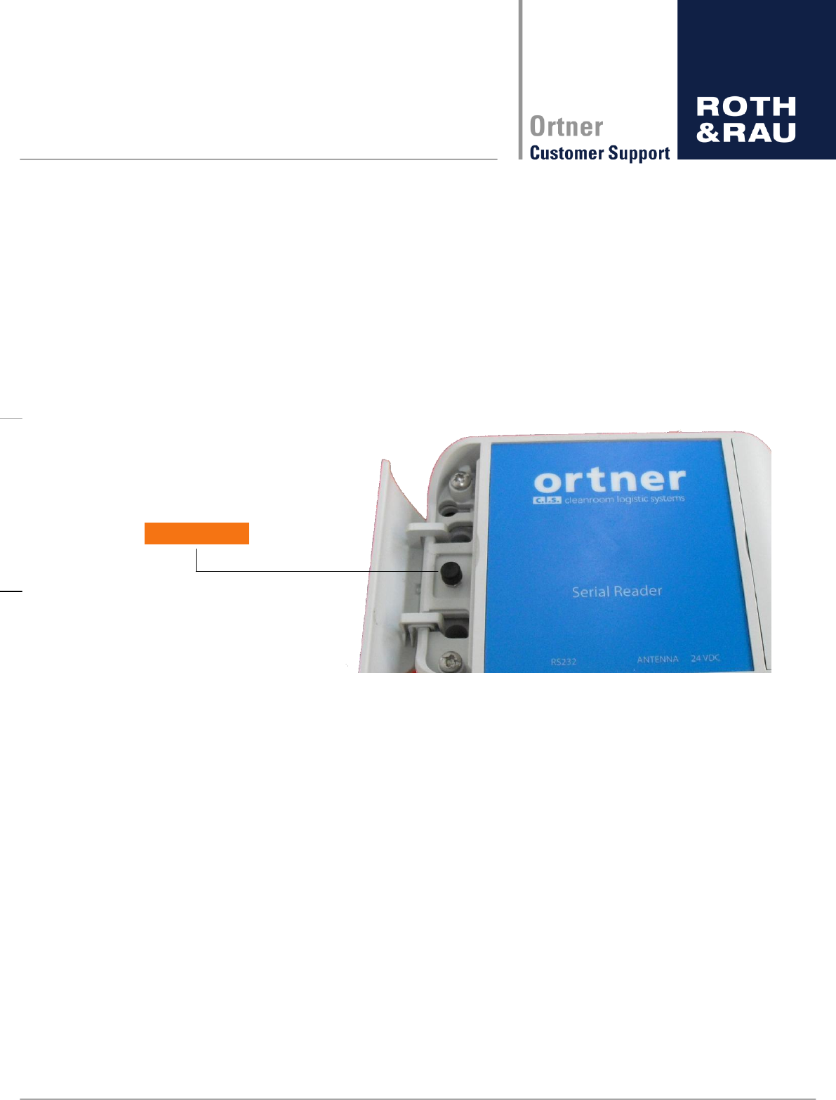
54 - 62
Revision: 3.5
LF-134-SER-P.M-V3.1 Manual
V3.5.docx
7.5 Test button
The LF-134-SER-P-V3.1 has a test button under the left cover to check easily communica-
tion or reading range manually.
p-
prox. 250msec as long as the button is pressed. The read result is send to the serial inter-
Red LED Read Error
Yellow LED Read Success
Test Button
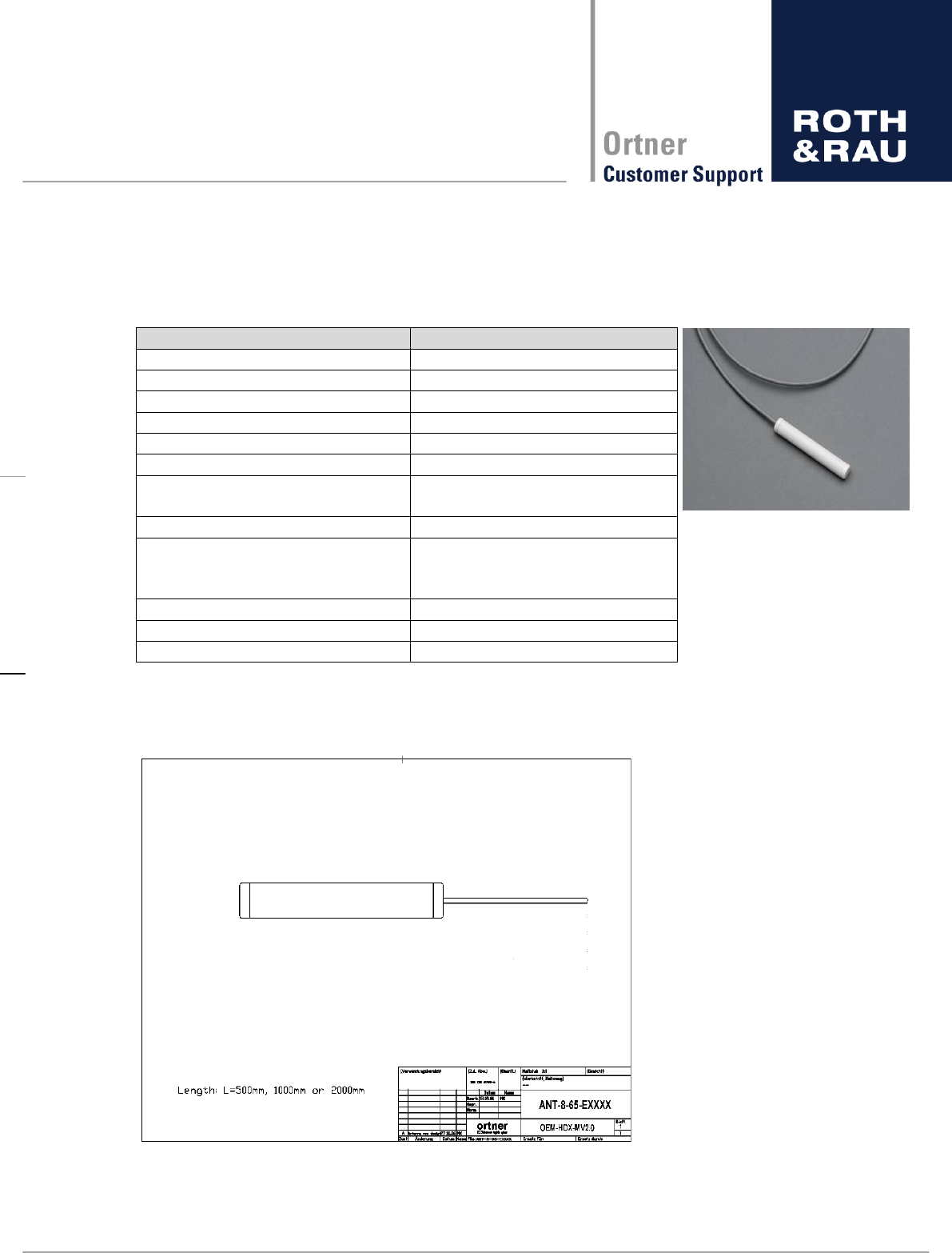
55 - 62
Revision: 3.5
LF-134-SER-P.M-V3.1 Manual
V3.5.docx
8 Antenna
8.1 Technical Specification
DESIGNATION
Frequency
134.2 kHz
Inductivity
47 µH
Core length
65 mm
Core diameter
8 mm
Total length (housing)
82 mm
Total diameter (housing)
13 mm
Housing material
Cap: PE (POLYETHYLENE)
Tube: PS (POLYSTYROL)
Cable type
1x2 AWG 22
Cable length
Default 500 mm, 1000 mm,
2000 mm, Custom lengths up to
2000 mm on request
Connector Reader side
Binder 3 pin (Series 712)
Connector Antenna side
n.a.
Only valid with
LF-134-SER-P/M-V3.x
Table 8-1: Specification of the Antenna
8.2 Drawing
Figure 8-1: Technical drawing of ANT-8-65-EXXXX

56 - 62
Revision: 3.5
LF-134-SER-P.M-V3.1 Manual
V3.5.docx
8.3 Maximum reading and writing ranges
The reading ranges are measured with best conditions; in real environment the ranges will
be much smaller due to disturbing material, like metal or other electro-magnetically fields
near the Antenna location. Please improve the condition before finally decision of the anten-
na location.
Writing ranges under same conditions are approx. 60% of the below described reading
ranges. Close to the antenna tag reading and writing will also be not possible, so prevent a
tag placement very close to the antenna, as a guide value prevent a distance below 10 mm.
Antenna cable, which is available as default, up to 2 m.
To prevent trouble please contact our support team if you expect problems with the place-
ment of the antenna in your special case!
Figure 8-2: Horizontal Pattern (10 mm/div)
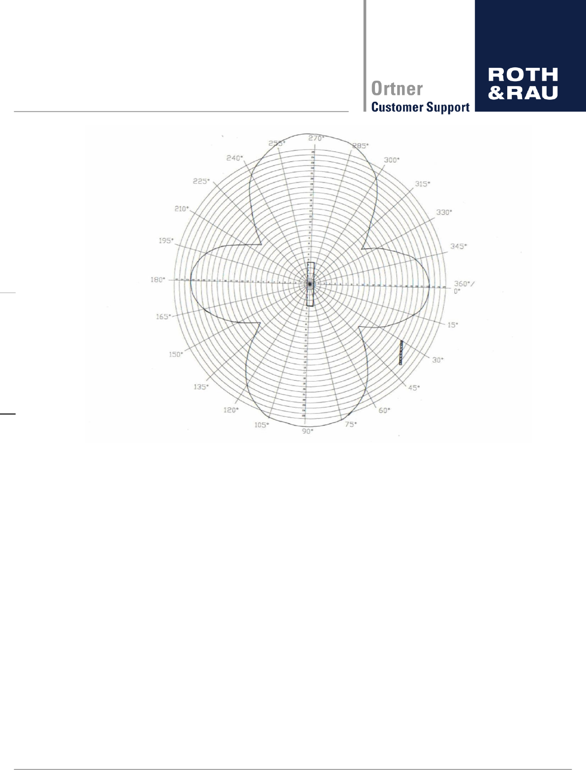
57 - 62
Revision: 3.5
LF-134-SER-P.M-V3.1 Manual
V3.5.docx
Figure 8-3: Vertical Pattern (10mm/div)
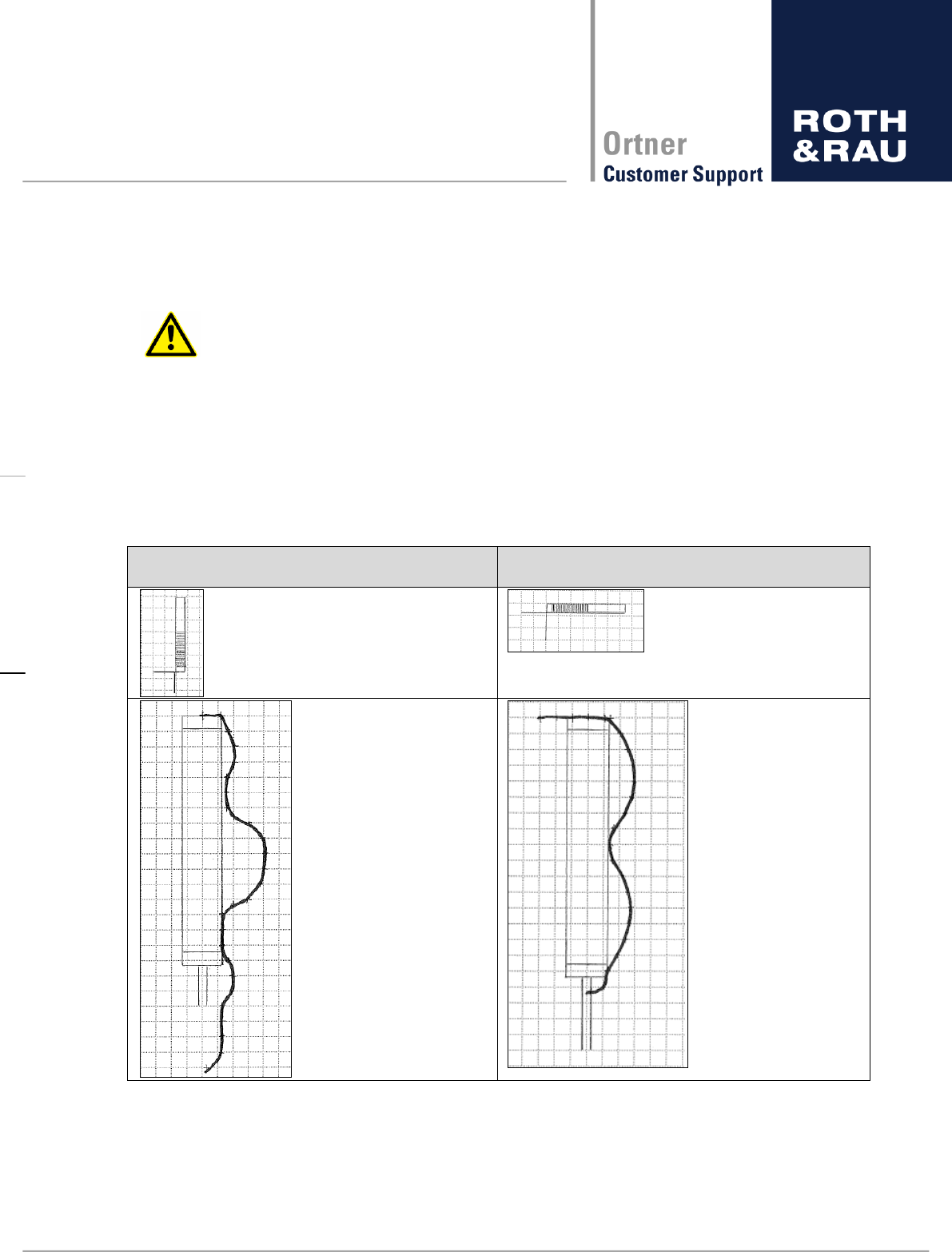
58 - 62
Revision: 3.5
LF-134-SER-P.M-V3.1 Manual
V3.5.docx
8.4 Minimum reading and writing range
Minimum reading and writing range means the range, which has to be kept between the an-
tenna and the transponder in order to have successful reading or writing.
Distances between antenna and transponder smaller than the minimum read-
ing and writing range are not allowed.
Minimum reading and writing range depends on antenna to transponder orientation. The fol-
lowing table shows the minimum reading and writing range for parallel and orthogonal orien-
tation between antenna and transponder. Minimum reading and writing range was measured
by the distance between the antenna housing boundary and the transponder boundary with a
standard antenna.
PARALLEL orientation between antenna
and transponder:
ORTHOGONAL orientation between an-
tenna and transponder:
Minimum reading and writing range decreases at theoretical zero points (where theoretically
no reading and writing is possible) and increases at theoretical maximum points. It can be
expected that the minimum reading and writing range has a scaled characteristic/course of
the maximum reading and writing range.
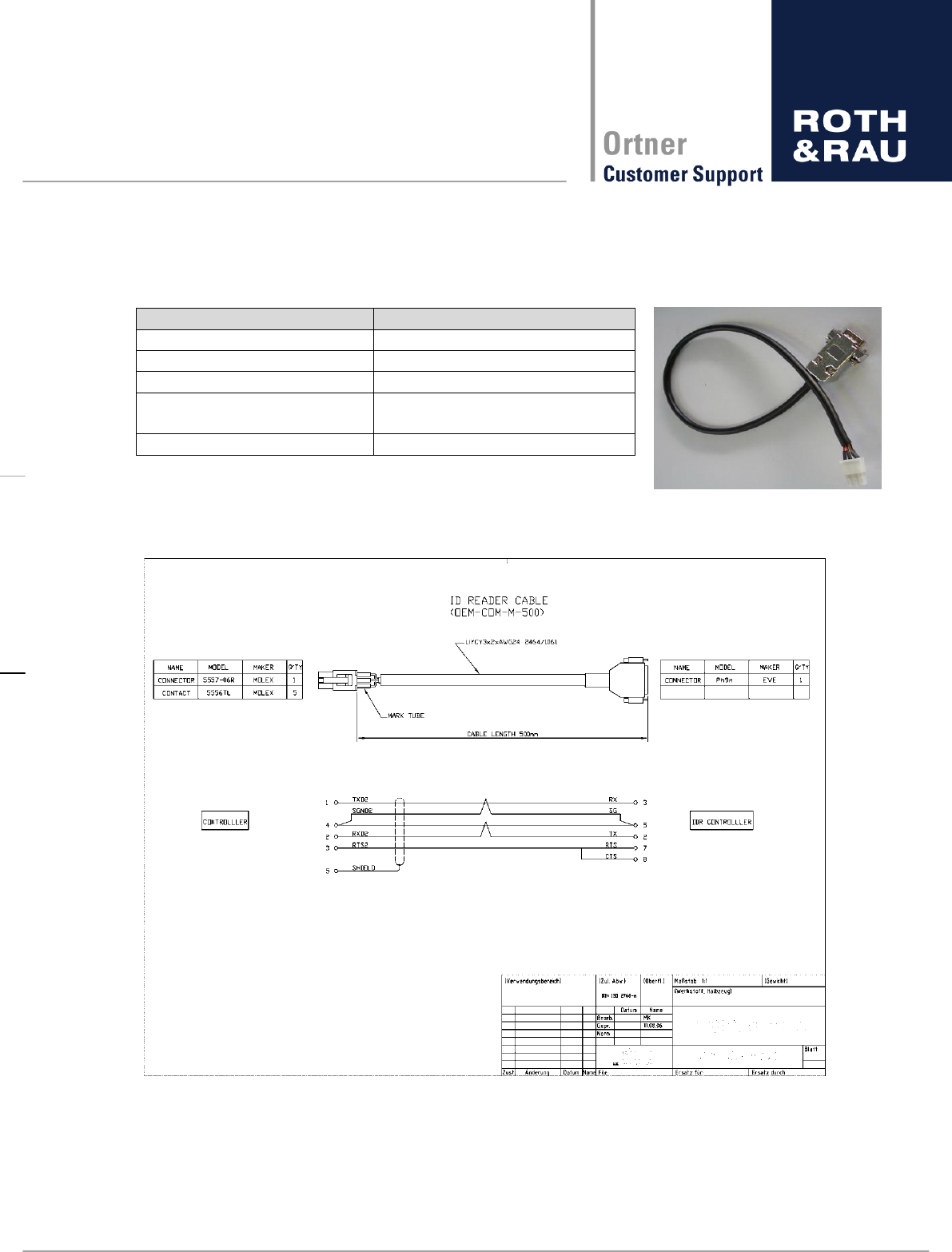
59 - 62
Revision: 3.5
LF-134-SER-P.M-V3.1 Manual
V3.5.docx
9 Communication cable
9.1 Technical Specification
DESIGNATION
Connector Reader side
Sub-D 9
Connector Host side
Molex 5557-06R
Cable type
3x2 AWG24
Cable length
Default 500 mm, Custom
lengths on request
Only valid with
LF-134-SER-P/M-V3.x
Table 9-1: communication cable
9.2 Drawing
Figure 0-1: Technical drawing OEM-COM-M-500
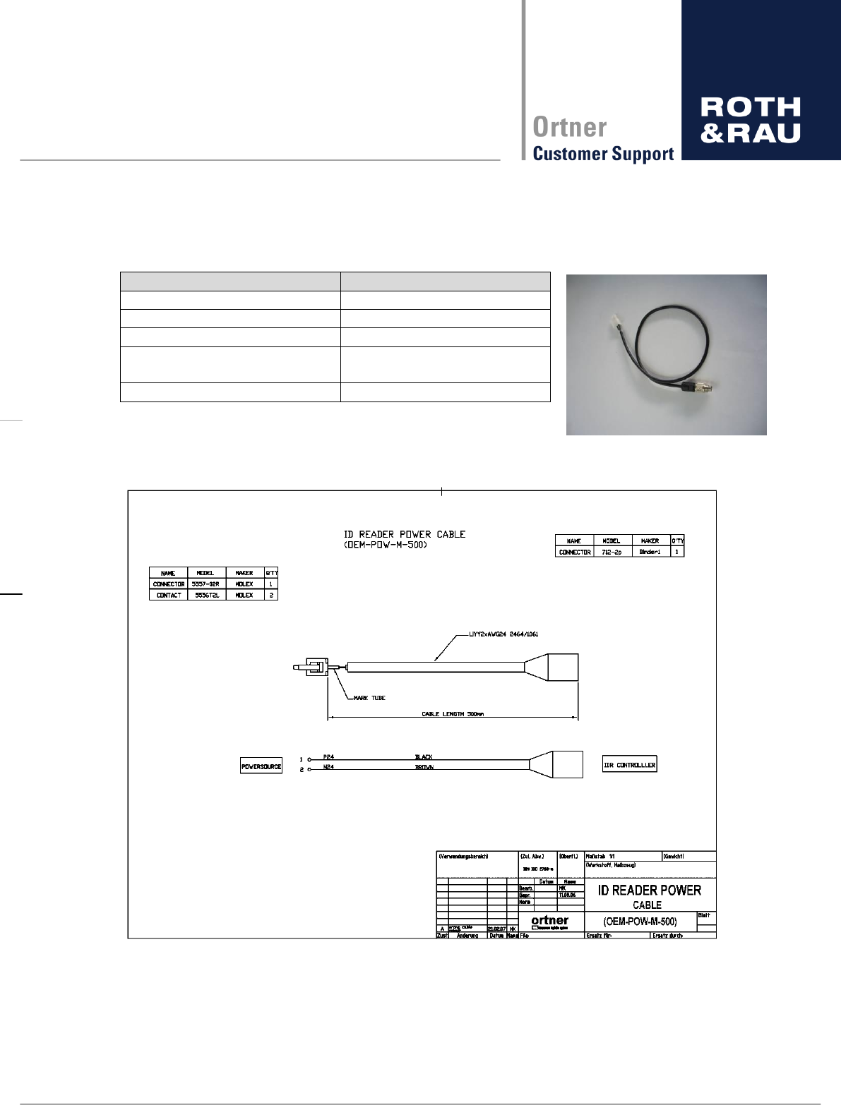
60 - 62
Revision: 3.5
LF-134-SER-P.M-V3.1 Manual
V3.5.docx
10 Power cable
10.1 Technical Specification
DESIGNATION
Connector Reader side
Binder 2 pin (Series 712)
Connector power supply side
Housing DF5A-3S-5C
Cable type
2x AWG24
Cable length
Default 500 mm, Custom
lengths on request
Only valid with
LF-134-SER-P/M-V3.x
Table 10-1: power cable
10.2 Drawing
Figure 10-1: Technical drawing OEM-POW-M-500
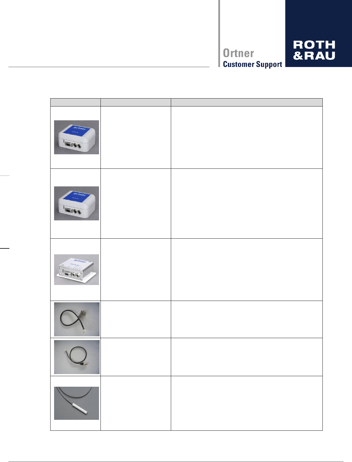
61 - 62
Revision: 3.5
LF-134-SER-P.M-V3.1 Manual
V3.5.docx
11 Parts ordering information
order code
Description
LF-134-SER-P-V3.0
product version 3.0 (plastic case)
134,2kHz, 24V DC, 500mA
external antenna connector: Binder series
712 - 3P (antenna not included)
communication interface: SUB-D9 (fe-
male), RS232
Please specify communication protocol!
(ASCII-L, ASCII-H, ASCII-A, SECS)
LF-134-SER-P-V3.1
product version 3.1 (plastic case)
134,2kHz, 24V DC, 500mA
external Test button
external antenna connector: Binder series
712 - 3P (antenna not included)
communication interface: SUB-D9 (fe-
male), RS232
Please specify communication protocol!
(ASCII-L, ASCII-H, ASCII-A, SECS)
LF-134-SER-M-V3.0
product version 3.0 (metal case)
134,2kHz, 24V DC, 500mA
external antenna connector: Binder series
712 - 3P (antenna not included)
communication interface: SUB-D9 (fe-
male), RS232
Please specify communication protocol!
(ASCII-L, ASCII-H, ASCII-A, SECS)
OEM-COM-M-XXXX
OEM-COM-M: communication cable,
OEM-POW-M-XXXX
OEM-POW-M: power cable,
cable length
ANT-8-65-EBXXXX
ANT: Antenna
core diameter (8 mm)
core length (65 mm)
antenna type (external)
connector type (Binder / RJ10)
cable length (500 mm / 1000 mm
/ 2000 mm)
Table 11-1 parts ordering information

62 - 62
Revision: 3.5
LF-134-SER-P.M-V3.1 Manual
V3.5.docx
© Roth & Rau - Ortner GmbH
Manfred-von-Ardenne-Ring 7
01099 Dresden / Germany
Tel. +49 351 888 61 0
Fax +49 351 888 61 20
ortner.info@roth-rau.com
www.roth-rau.com/ortner