Farpointe Data DELTA Proximity RFID Tag Reader User Manual Delta Referece CORR
Farpointe Data Inc. Proximity RFID Tag Reader Delta Referece CORR
Users Manual
Delta Series Mifare Readers Quick Reference Guide
2177 Leghorn Street 05465-001 Rev. 1.1
Mountain View, CA 94043-1605 USA 1 of 2
Tel: +1-650-964-2615 Fax: +1-650-988-6687
Web: http://www.farpointedata.com E-mail: sales@pyramidseries.com
The Delta Series models include the Delta3, Delta5, and Delta 6.4. The Delta 6.4 is simply a Delta5 with a
keypad attachment.
All Delta Series Readers are compliant with the following organizations:
FCC compliance Statement: This device complies with part 15 of the FCC rules. Operation is subject to the
following two conditions: (1) this device may not cause harmful interference, and (2) this device must accept any
interference received, including interference that may cause undesired operation. Changes made to this
equipment that is not authorized by Farpointe Data Inc. may void the user’s authority to operate the equipment.
1.0 Cable Requirements
All readers operate at up to 500 feet (152 m) of cable, using nine-conductor, shielded, stranded cable. Per the
Security Industry Association’s Wiegand specification, AWG 24 (such as Belden 9539) is the minimum gauge
required for data transfer in a 500-foot run length. However, the proper wire gauge to use must be determined by
the current draw requirements of the reader, the length of the cable run, and the voltage applied to the reader.
If the reader is to be operated at 5 VDC, 5 VDC must be available at the reader (long cable runs have a voltage
drop due to the resistance in the cable). A larger gauge of wire (having less resistance) or a separate power
supply near the reader may be required to ensure 5 VDC is available at the reader.
2.0 Reader Modes
Delta Series readers can be configured to operate in any of the following modes:
• Sector Only Mode: Reader looks for access control data in a secure sector but if no valid data is found
the reader outputs nothing. This is the default mode.
• CSN Only Mode: Reader does not look for access control data in a secure sector data and simply
outputs the card’s CSN.
• Sector Plus CSN Mode: reader looks for access control data in a secure sector but if none is found the
reader outputs the card’s CSN instead.
3.0 CSN Output Formats
Delta Series readers can be configured to output the card’s CSN in any of the following ways:
• 32-bit Wiegand: The reader outputs the 32-bit CSN as Wiegand data starting with the MSB. This is
the default mode.
• 26-bit Wiegand: The reader outputs 26-bit Wiegand data comprised of the 16 lower bits of the 32-bit
CSN, fixed 8-bit facility code, and beginning and ending parity bits. Facility code defaults to 001
(Note: cutting off 16 MSBs from CSN can cause card duplication).
• 34-bit Wiegand: The reader outputs 34-bit Wiegand data comprised of the 32-bit CSN MSB first plus
beginning and ending parity bits.
• 40-bit Wiegand: The reader outputs 40-bit Wiegand data comprised of the 32-bit CSN followed by an
8-bit check sum.
• Magnetic Stripe (ABA Track II, clock and data, with card present): 32-bit CSN is output in ABA Track
II format.
4.0 Secure Sector Access Control Data Output Formats
Access control data programmed onto a secure mifare sector can be output in any of the following ways:
• Wiegand (industry standard 26-bit Wiegand and custom formats)
• Magnetic Stripe (ABA Track II, clock and data, with card present)
5.0 Grounding
Shield (drain) continuity must run from the reader to the access panel. Shield (drain) and reader ground must be
tied together at the access panel and connect to an earth ground at one point.
6.0
Power
Reference Document Delta Series Mifare Readers
Delta Series Mifare Readers Quick Reference Guide
2177 Leghorn Street 05465-001 Rev. 1.1
Mountain View, CA 94043-1605 USA 2 of 2
Tel: +1-650-964-2615 Fax: +1-650-988-6687
Web: http://www.farpointedata.com E-mail: sales@pyramidseries.com
A reader may be powered by the access panel, so the reader is powered on when the access supply is powered on.
However the best case is to power the reader by a separate, linear power supply.
7.0 Voltage
• Can range from 5 to 14 VDC, 12 VDC is nominal
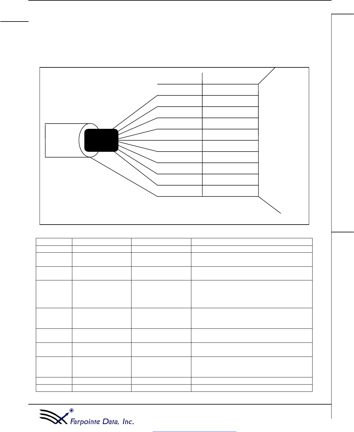
8.0 Reader Wiring
Please note that at minimum the power, ground, data 0, and data 1 lines must be connected to the access panel.
Other lines are for additional functionality.
9.0 Connections in Detail
Wire Color Line I/O Description
Red Reader Input voltage Input 5 to 14 VDC
Green Wiegand data 0/
Magstripe Clock Output Wiegand data or ABA Track II clock
White Wiegand data 1/
Magstripe Data Output Wiegand data or ABA Track II data
Brown Red LED host control Input LED host control. In single line LED control
mode (default mode) pull line low to turn on
green LED. In dual line LED mode pull line
low to turn on Red LED
Orange Green LED host
control Input LED host control, only used in dual LED mode.
In dual LED mode pull line low to turn on
green LED.
Blue Audio tone host
control Input Beeper host control. Pull line low for beep.
Purple Read mode control Input Read mode host control. Pull line low for
“CSN Only” mode.
Yellow Card Present Output (can be
configured as TTL or
open collector)
Card present line for ABA Track II magnetic
stripe output.
Black Reader Ground Input Reader Ground
Silver Cable shield N/A Cable shield (drain), should be grounded
Wire
Color
Function
Green
Blue
Red
Pur
p
le
Brown
Shield
(
Drain
)
White
Yellow
Black
Silver
Data
0
Bee
p
er
Reader
Power
Read
Mode
LED
line
1
LED
line
2
Data
1
Card
Present
Reader
Ground
Oran
g
e
Figure 1: Wiring Connections to Access Panel
Access
Panel
Reference Document Delta Series Mifare Readers

Delta Series Mifare Readers Quick Reference Guide
2177 Leghorn Street 05465-001 Rev. 1.1
Mountain View, CA 94043-1605 USA 3 of 2
Tel: +1-650-964-2615 Fax: +1-650-988-6687
Web: http://www.farpointedata.com E-mail: sales@pyramidseries.com
Mifare® is a registered trademark of Philips Electronics N.V.