Farsun Photoelectric Science Technologies FG2800 Wireless Barcode Scanner User Manual FG2600
Farsun Photoelectric Science Technologies co., LTD Wireless Barcode Scanner FG2600
User manual
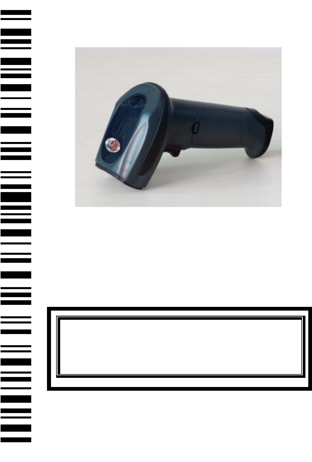
Barcode scanner
User¶s Manual
2
Contents
Programming with Parameter .............................................................. 4
Interface selection ...................................................................................... 6
Scanning Mode Setting ............................................................................... 7
Keyboard wedge ......................................................................................... 9
USB interface ............................................................................................ 11
RS-232 Interface ....................................................................................... 12
Global Settings .......................................................................................... 16
Indication .................................................................................................. 21
EAN-13 and ISBN/ISSN .............................................................................. 22
EAN-8 ........................................................................................................ 24
UPC-A ........................................................................................................ 23
UPC-E ........................................................................................................ 28
Code128 C................................................................................................. 28
Code 39 ..................................................................................................... 29
Code 93 ..................................................................................................... 32
Interleaved 2 of 5 ..................................................................................... 34
Industrial 2 of 5 ......................................................................................... 38
Matrix 2 of 5 ............................................................................................. 40
Codabar .................................................................................................... 37
Code 11 ..................................................................................................... 38
MSI/Plessey .............................................................................................. 44
UK/Plessey ................................................................................................ 46
3
GS1 DataBar (GS1 DataBar Truncated) ..................................................... 44
GS1 DataBar Limited ................................................................................. 45
GS1 DataBar Expanded ............................................................................. 50
Advanced Bar Code Data Formatting ....................................................... 51
Prefix ................................................................................................... 51
Suffix ................................................................................................... 52
Preamble ............................................................................................ 52
Postamble ........................................................................................... 53
Code ID ............................................................................................... 48
Code ID position ................................................................................. 48
Code name transmission .................................................................... 49
Code length transmission ................................................................... 49
Case conversion: ................................................................................. 49
Insert String G1 Setting ....................................................................... 50
Insert String G2 Setting ....................................................................... 50
Insert String G3 Setting ....................................................................... 50
Insert String G4 Setting ....................................................................... 51
FN1 substitution string setting ........................................................... 51
Truncate leading G5 String setting ..................................................... 57
Truncate ending G6 string setting ...................................................... 57
Replace String Setting ......................................................................... 58
Appendix 1 ASCII Table 1-2 ....................................................................... 53
Appendix 2 Parameter bar code ............................................................... 55
**Wireless Communication Setting͙͙͙͙͙͙͙͙͙͙͙͙͙͙͙͙͙͙͙͙͙.56
Wireless Channel͙͙͙͙͙͙͙͙͙͙͙͙͙͙͙͙͙͙͙͙͙͙͙͙͙͙͙.͙͙͙..57
RF operĂƚŝŶŐŵŽĚĞ͙͙͙͙͙͙͙͙͙͙͙͙͙͙͙͙͙͙͙͙..͙͙͙͙͙͙͙͙͙58
4
Battery Status͙͙͙͙͙͙͙͙͙͙͙͙.͙͙͙͙͙͙͙͙͙͙͙͙͙͙͙͙͙͙͙.. 59
Programming with Parameter
It is need to scan more than one setting barcode to program the scanner
with parameter.
Program Parameters
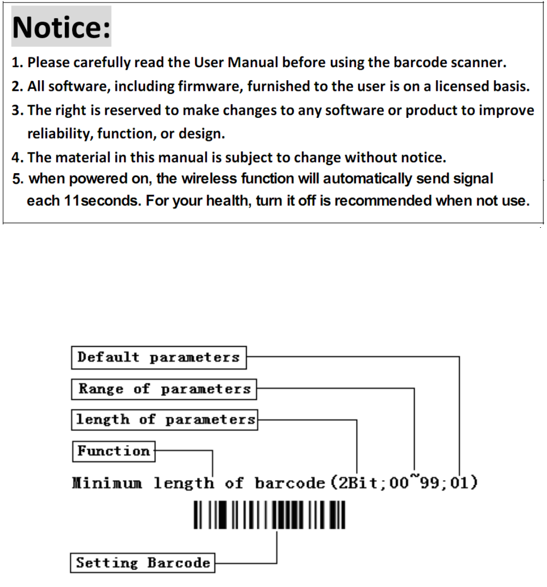
Notice:
1. Please carefully read the User Manual before using the barcode scanner.
2. All software, including firmware, furnished to the user is on a licensed basis.
3. The right is reserved to make changes to any software or product to improve
reliability, function, or design.
4. The material in this manual is subject to change without notice.
. when powered on, the wireless function will automatically send signal
each 11seconds. For your health, turn it off is recommended when not use.
5

5
The steps of programming are:
1. 6FDQWKH)XQFWLRQ6HWWLQJ%DUFRGH7KH6FDQQHUZLOOLVVXHDEHHS´
sound, and the Red LED is on until the program is finished.
2. Scan the parameters bar code. The parameters may be one or more than
one digits.
3. 6FDQWKHVHWWLQJEDUFRGH³)LQLVK6HWWLQJ´,ILWLVSURJUDPPHG
VXFFHVVIXOWKHVFDQQHUZLOOLVVXHD³EHHSEHHS´VRXQGEXWLVVXHD
³EHHSEHHSEHHS´VRXQGZKHQIDLOV
e.g.
˖
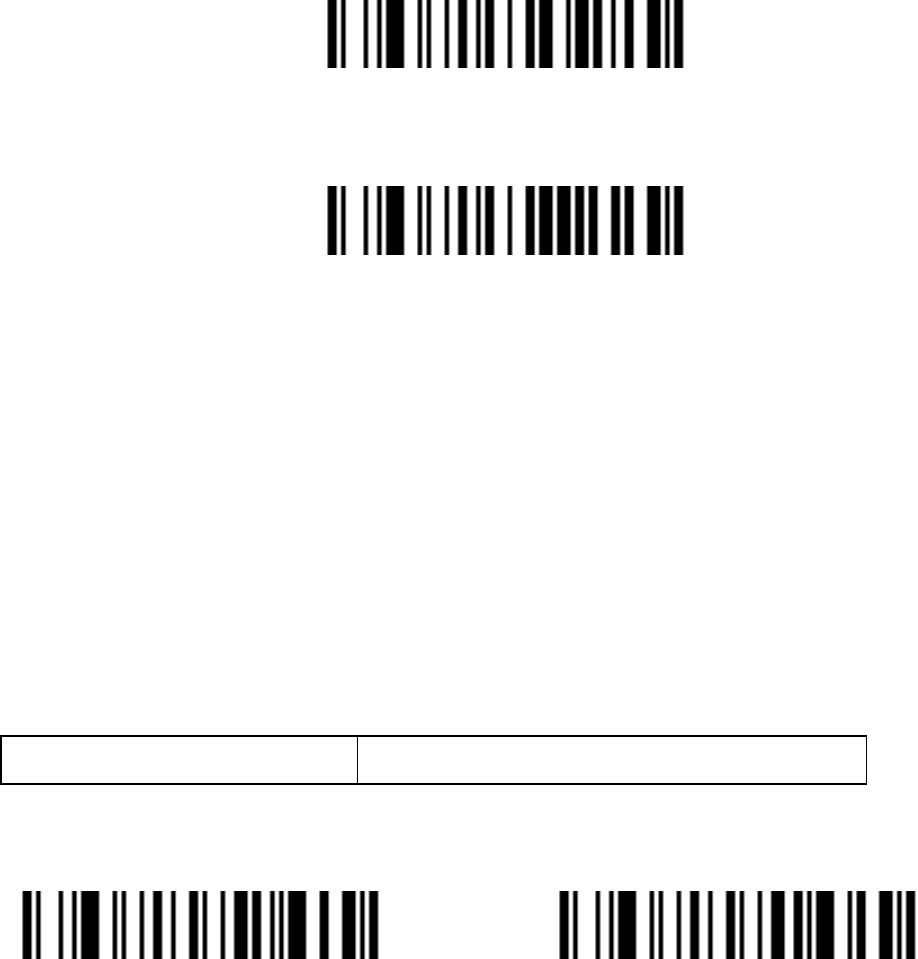
Set min. code length of Code 128 to 5 chars
˖
ƻ
1˖Open the manual and turn chapter "code128 ". Scan the setting bar code
³Scan Min. Code Length´
Scan Min. Code Length˄2 Digits˗00~99ˈ1*˅
ƻ
2˖Turn to the last page of this Manual Appendix 10 Parameter bar code,
VFDQWKHSDUDPHWHUEDUFRGH³´DQG ³´˖
0
5

6
ƻ
3˖6FDQ³)LQLVK6HWWLQJ´ILQLVKWKHVHWWLQJ.
Finish Setting
Set Factory Defaults
If you wish to return the base unit to the entire factory default settings (radio
FRPPXQLFDWLRQVHWWLQJLVQRWLQFOXGHGVFDQWKHEDUFRGH´Set Defaults´
Set Defaults
Interface selection
This scanner supports interfaces such as keyboard wedge, RS-232 serial
wedge, and USB interface.
Typically, host is able to identify the host port type automatically. In extreme
cases, host port may need setting manually if the host fails to identify it.
AutomaticIdentification*
USB

7
PS/2KeyBoard RS232
Scanning Mode Setting
Good-read off scanning Mode: The trigger button must be pressed once
to activate scanning. The light source of scanner stops scanning when there
is a successful reading or no code is decoded after the Stand-by duration
elapsed.
Select Good-read off scanning Mode *

8
Auto-detection scanning Mode: The scanner will start scan Automatically
if any object enter the scan area. The laser light of scanner stops scanning
when there is a successful reading or no code is decoded after the Stand-by
duration elapsed. Once the laser light stops scanning, the present object must
be remove away from the scan area to enable Auto-detect sensor.
Select Auto-detection scan
Press Scanning Mode˖It can continue scan barcode when the button is
continuing pressed.
Press Scanning Mode
Click Scanning Mode: When the button is click, the scanner will keep
scanning the barcode until the barcode is reader or the Stand-by duration
elapsed.
Click Scanning Mode
Continuous Scanning mode: the scan engine is always scanning and
decoding. The module will read the barcode which gets into the scanning
area automatically. Only when the barcode that has been read gets out of the
scanning area, the module can read the next barcode.

9
Select Continuous Scanning mode
Auto Continue mode: The scanner will start continuous scan Automatically
if any object enter the scan area. When there is no bar code is read for half a
minute, the scanner shutdown the laser line and exit continuous scanning
mode.
Auto Continue mode
Keyboard wedge
Keyboard type IBM ATˈPS/2 *

10
Other˄Reserved˅
Keyboard layout
USA *
Italian
French
Turkish F
Turkish Q

11
USB interface
USB device type
HID Keyboard* Virtual RS232 Port˄reserved˅
Note: Virtual RS232 Port need driver!
IBM Table Top USB IBM Hand-Held USB
USB OPOS Hand-Held
USB Keyboard layout
USA* German
French Other

12
RS-232 Interface
Baud Rate
2400
4800
9600*
19200
38400

13
57600
Handshaking
None
˖
Scan the bar code below if no Hardware Handshaking is desired
None˄Default˅
Standard RTS/CTS
˖
Scan the bar code below to select Standard RTS/CTS
Hardware Handshaking.
Standard RTS/CTS
RTS/CTS Option 1: When RTS/CTS Option 1 is selected, the scanner
asserts RTS before transmitting and ignores the state of CTS. The scanner
de-asserts RTS when the transmission is complete.
RTS/CTS Option 1
RTS/CTS Option 2: When Option 2 is selected, RTS is always high or low
(user-programmed logic level). However, the scanner waits for CTS to be
asserted before transmitting data. If CTS is not asserted within Host Serial
Response Time-out, the scanner issues an error indication and discards the

14
data
RTS/CTS Option 2
RTS/CTS Option 3: When Option 3 is selected, the scanner asserts RTS
prior to any data transmission, regardless of the state of CTS. The scanner
waits up to Host Serial Response Time-out for CTS to be asserted. If CTS
is not asserted during this time, the scanner issues an error indication and
discards the data. The scanner de-asserts RTS when transmission is
complete.
RTS/CTS Option 3
ACK/NAK: When this option is selected, after transmitting data, the scanner
expects either an ACK or NAK response from the host. When a NAK is
received, the scanner transmits the same data again and waits for either an
ACK or NAK. After three unsuccessful attempts to send data when NCK are
received, the scanner issues an error indication and discards the data.
ACK/NCK
ENQ: When this option is selected, the scanner waits for an ENQ character
from the host before transmitting data. If an ENQ is not received within the
Host Serial Response Time-out, the scanner issues an error indication and

15
discards the data. The host must transmit an ENQ character at least every
Host Serial Response Time-out to prevent transmission errors.
ENQ
ACK/NAK with ENQ: This combines the two previous options. For
re-transmissions of data, due to a NAK from the host, an additional ENQ is
not required. ACK/NCK with ENQ
XON/XOFF: An XOFF character turns the scanner transmission off until
the scanner receives an XON character. There are two situations for
XON/XOFF:
;2))LVUHFHLYHGEHIRUHWKHVFDQQHUKDVGDWDWRVHQG:KHQWKHVFDQQHU
has data to send, it waits up to Host Serial Response Time-out for an XON
character before transmission. If the XON is not received within this time,
the scanner issues an error indication and discards the data.
;2))LVUHFHLYHGGXULQJDWUDQVPLVVLRQ'DWDWUDQVPLVVLRQWKHQVWRSVDIWHU
sending the current byte. When the scanner receives an XON character, it
sends the rest of the data message. The scanner waits up to 30 seconds for
the XON
XON/XOFF

16
RTS Line State
Host: Low RTS ˄Default˅
Host: High RTS &RH
Host Serial Response Time-out
2 sec˄Default˅ 5 sec
7.5 sec 10 sec
Data Bits
7-Bit 8-Bit*˄Default˅
Stop Bit Select
1 Stop Bit˄Default˅ 2 Stop Bit

17
Parity None*˄Default˅
Odd
Even
Select Mark parity and the parity bit is always 1.
Mart
Select Space parity and the parity bit is always 0.
Space
Global Settings
Element amendment
Enable Element amendment *
Disable Element amendment

18
Printable character Output only
Enable
Disable*
Decoder optimization
Enable Decoder optimization *
Disable Decoder optimization
Save Power
Enable*
Disable

19
Standby duration
2 second
5 second *
10 second
20 second
Double confirm
Disable Double confirm* 5 Times

20
2 Times 10 Times
Same barcode delay time
If a barcode has been scanned and output once successfully, the laser beam
must be off or moved away from the barcode beyond delay time to active
VFDQQLQJWKHVDPHEDUFRGH:KHQWKLVIHDWXUHLVVHWWREH³[))´WKHQWKH
delay time is indefinite.
Same barcode delay time˄2 Digits;00~99;00*˅
Global Max./Min. code length
Global Max. code length˄2 Digits;00~99;99*)
Global Min. code length˄2 Digits;00~99;XX*)

21
Global G1-G6 string selection
Global Insert String 1(1 Digits˗0~6; 0*)
Global Insert String 2(1 Digits˗0~6; 0*)
Decode UPC/EAN Only With Supplemental
Enable Disable *
Indication
Volume of beeper High*
Middle
Low
Mute

22
Beep tone High Tone
Middle Tone *
Low Tone
EAN-13 and ISBN/ISSN
Enable/Disable EAN-13
Enable EAN-13* Disable EAN-13
EAN-13 Check Digit Verification
Enable EAN-13 Check Digit Verification *

23
Disable EAN-13 Check Digit Verification
EAN-13 Check Digit Transmission
Transmit EAN-13 Check Digit*
Do Not Transmit EAN-13 Check Digit
EAN13 Supplement Digits
2 Digits
5 Digits
2 Digits or 5 Digits
None*

24
ISBN/ISSN Conversion
Convert EAN-13 to ISBN/ISSN
Do Not Convert EAN-13 to ISBN/ISSN*
EAN-8
Enable/Disable EAN-8
Enable EAN-8*
Disable EAN-8
EAN-8 Check Digit Verification
Enable EAN-8 Check Digit Verification *
Disable EAN-8 Check Digit Verification

25
EAN-8 Check Digit Transmission
Transmit EAN-8 Check Digit L*
Do Not Transmit EAN-8 Check Digit
EAN-8 Supplement Digits
2 Digits
5 Digits
2 Digits or 5 Digits
None*

26
Expand EAN-8 to EAN-13
Expand to EAN-13 Do Not Convert to EAN-13*
EAN-8 &RGH,'VHWWLQJ³G´
Scan Code ID˄2 Digits˗00~FF˗ 64*˅
UPC-A
Enable UPC-A 0* Disable UPC-A
UPC-A Check Digit Verification
Enable UPC-A Check Digit Verification *
Disable UPC-A Check Digit Verification
UPC-A Check Digit Transmission

27
Transmit UPC-A Check Digit *
Do Not Transmit UPC-A Check Digit
Supplement Digits
2 Digits 5 Digits
2 Digits or 5 Digits None *
UPC-A Truncation/Expansion
Expand UPC-A to EAN-13
Truncate leading zeros
None*

28
UPC-E
Enable/Disable UPC-E
Enable UPC-E* Disable UPC-E
UPC-E Check Digit Verification
Enable UPC-E Check Digit Verification *
Disable UPC-E Check Digit Verification
UPC-E Check Digit Transmission
Transmit UPC-E Check Digit *
Do Not Transmit UPC-E Check Digit

29
Supplement Digits
2 Digits 5 Digits
2 Digits or 5 Digits None*
UPC-E Truncation/Expansion
Truncate leading zeros
Expand UPC-E to EAN-13
Expand UPC-E to UPC-A
None*

30
Code128 C
Enable Code 128* Disable Code 128
Code128 Check Digit Verification
Enable Code 128 Check Digit Verification *
Disable Code 128 Check Digit Verification
Code 128 Check Digit Transmission
Transmit Code 128 Check Digit *
Do Not Transmit Code 128 Check Digit

31
Code128 Length
Scan Max. Code Length˄2 Digits˗00~99˗99*˅
Scan Min. Code Length˄2 Digits˗00~99ˈ1*˅
UCC/EAN 128
Enable/Disable UCC/EAN 128
Enable* Disable
UCC/EAN 128 Check Digit Verification
Enable* Disable

32
UCC/EAN 128 Check Digit Transmission
Transmit Check Digit * Do Not Transmit Check Digit
UCC/EAN 128 Length
Scan Max. Code Length˄2 Digits˗00~99˗99*˅
Scan Min. Code Length˄2 Digits˗00~99ˈ1*˅
Code 39
Enable/Disable Code 39
Enable* Disable
Code 39 Check Digit Verification

33
Enable Disable*
Code 39 Check Digit Transmission
Transmit Code 39 Check Digit Do Not Transmit Code 39 Check Digit *
Code 39 Full ASCII Conversion
Enable Code 39 Full ASCII Disable Code 39 Full ASCII *
Start/End transmission
Enable Code 39 Start/End transmission
Disable Enable Code 39 Start/End transmission *

34
Convert Code 39 to Code 32
Enable Convert Code 39 to Code 32
Disable Convert Code 39 to Code 32*
&RGH3UHIL[³$´WUDQVPLVVLRQ
Enable &RGH3UHIL[³$´WUDQVPLVVLRQ
Disable &RGH3UHIL[³$´WUDQVPLVVLRQ*
³´DVGDWDFKDUDFWHU
Enable

35
Disable*
Code39 Length
Scan Max. Code Length˄2 Digits˗00~99˗99*˅
Scan Min. Code Length˄2 Digits˗00~99˗1*˅
Code 93
Enable/Disable Code 93
Enable* Disable
Code 93 Check Digit Verification
Enable Code 93 Check Digit Verification *

36
Disable Code 93 Check Digit Verification
Code 93 Check Digit Transmission
Transmit Check Digit *
Do Not Transmit Check Digit
Code 93 Full ASCII Conversion
Enable Code 93 Full ASCII
Disable Code 93 Full ASCII *
37
Code 93 Length
Scan Max. Code Length˄2 Digits˗00~99˗99*˅
Scan Min. Code Length˄2 Digits˗00~99ˈ1*˅
Interleaved 2 of 5
Data digits (Variable) Check digit (one bit ,optional)
Interleaved 2 of 5 Enable* Disable

38
Interleaved 2 of 5 Check Digit Verification
Enable Disable*
Interleaved 2 of 5 Check Digit Transmission
Transmit Check Digit Do Not Transmit Check Digit *
Interleaved 2 of 5 Length
Scan Max. Code Length˄2 Digits˗00~99˗99*˅
Scan Min. Code Length˄2 Digits˗00~99ˈ1*˅
Industrial 2 of 5
Enable/Disable Industrial 2 of 5

39
Enable* Disable
Industrial 2 of 5 Check Digit Verification
Enable Disable *
Industrial 2 of 5 Check Digit Transmission
Transmit Check Digit Do Not Transmit Check Digit *
Industrial 2 of 5 Length
Scan Max. Code Length˄2 Digits˗00~99˗99*˅
Scan Min. Code Length˄2 Digits˗00~99ˈ1*˅

40
Matrix 2 of 5
Enable/Disable Matrix 2 of 5
Enable* Disable
Matrix 2 of 5 Check Digit Verification
Enable Disable *
Matrix 2 of 5 Check Digit transmission
Transmit Check Digit Do Not Transmit Check Digit *
Matrix 2 of 5 Length
Scan Max. Code Length˄2 Digits˗00~99˗99*˅
Scan Min. Code Length˄2 Digits˗00~99ˈ1*˅

41
Coda bar
Enable/Disable Codabar
Enable* Disable
Coda bar Check Digit Verification
Enable Disable*
Coda bar Check Digit Transmission
Transmit Check Digit Do Not Transmit Check Digit *
Coda bar Start/End type
ABCD/ABCD * abcd/abcd

42
ABCD/TN*E abcd/tn*e
Coda bar Start/End transmission
Enable
Disable *
Coda bar Length
Scan Max. Code Length˄2 Digits˗00~99˗99*˅
Scan Min. Code Length˄2 Digits˗00~99ˈ1*˅

43
Code 11
Enable/Disable Code 11
Enable* Disable
Code 11 Check Digit Verification
Enable 1bit check Digit *
Enable 2 bit check Digit
Disable check Digit
Code 11 Check Digit Transmission
Transmit Code11 Check Digit Do Not Transmit Code11 Check Digit *

44
Code 11 Length
Scan Max. Code Length˄2 Digits˗00~99˗99*˅
Scan Min. Code Length˄2 Digits˗00~99ˈ4*˅
MSI/Plessey
Enable/Disable MSI/Plessey
Enable *0
Disable
MSI/Plessey Check Digit Verification

45
Enable 1 digit˄Mod10˅
Enable 2 digit˄Mod10/10˅
Enable 2 digit˄Mod11/10˅
Disable*
MSI/Plessey Check Digit Transmission
Transmit MSI/Plessey Check Digit
Do Not Transmit MSI/Plessey Check Digit *

46
MSI/Plessey Length
Scan Max. Code Length˄2 Digits˗00~99˗99*˅
Scan Min. Code Length˄2 Digits˗00~99ˈ4*˅
UK/Plessey
Check digit verification: The UK/Plessey has two optional check digits. The
check digit 1 and check digit 2 will be calculated as the sum module 10 or 11
of the data digits.
Enable UK /Plessey * Disable UK /Plessey

47
UK/Plessey Check Digit Verification
Enable* Disable
UK /Plessey Check Digit Transmission
Transmit Check Digit Do Not Transmit Check Digit *
UK/Plessy Lenght
Scan Max. Code Length˄2 Digits˗00~99˗99*˅
Scan Min. Code Length˄2 Digits˗00~99ˈ1*˅
GS1 DataBar (GS1 DataBar Truncated)
GS1 DataBar Truncated is structured and encoded the same as the standard
GS1 DataBar format, except its height is reduced to a 13 modules minimum;
while GS1 DataBar should have a height greaterthan or equal to 33 modules.

48
Enable/Disable GS1 DataBar
Enable * Disable
Conversion
Convert GS1 DataBar to UCC/EAN 128
Convert GS1 DataBar to UPC-A or EAN-13
Disable Conversion *
GS1 Data Bar Limited
Enable/Disable GS1 DataBar Limited

49
Enable* Disable
Conversion
Convert GS1 DataBar Limited UCC/EAN 128
Convert GS1 DataBar Limited UPC-A OR EAN-13
Disable Conversion*

50
GS1 DataBar Expanded
Enable/Disable GS1 DataBar Expanded
Enable* Disable
Conversion
Convert GS1 DataBar to UCC/EAN 128 Disable Conversion*
GS1 DataBar Expanded Lenght
Scan Max. Code Length˄2 Digits˗00~99˗99*˅
Scan Min. Code Length˄2 Digits˗00~99ˈ1*˅
51
Advanced Bar Code Data Formatting
Format of barcode data transmission˖
Prefix Code
name
Preamble Code
ID
Code
length
Code
data
Code
ID
Postamble Suffix
Suffix Quick Setup
CR *L0 LF
CR & LF None
Prefix
Transmit Prefix:
Do Not Transmit Prefix *
Scan Prefix˄0~16 Charsˈ2 Digits /Char˗00~FF˗ 00*˅

52
Suffix
The default Suffix is CRDŽ
Transmit Suffix *
Do Not Transmit Suffix
Scan Suffix˄0~22 Charsˈ2 Digits /Char˗00~FF˗ 00*˅
Preamble
Transmit Preamble
Do Not Transmit Preamble *

53
Scan preamble˄0~16 Charsˈ2 Digits /Char˗00~FF˗ 00*˅
Postamble
Transmit Postamble
Do Not Transmit Postamble *
Scan Postamble˄0~16 Charsˈ2 Digits /Char˗00~FF˗ 00*˅
Code ID
Transmit Proprietary ID
Transmit AIM ID
Do Not Transmit Code ID*

54
Code ID position
Before code data After code data *
Code name transmission
Transmit Code name Do Not Transmit Code name *
Code length transmission
Transmit Code length Do Not Transmit Code length *
Case conversion:
The characters within code data or the whole output string can be set in
either upper case or lower case
Disable*
Upper (data only)

55
Lower (data only)
Upper (whole string)
Lower (whole string)
Insert String G1 Setting
Scan Inert String G1˄0~16 Charsˈ2 Digits /Char˗00~FF˗ 00*˅
Scan the Position of G1˄2 Digits˗00~99˗ 00*˅
Insert String G2 Setting
Scan Inert String G2˄0~16 Charsˈ2 Digits /Char˗00~FF˗ 00*˅
Scan the Position of G2˄2 Digits˗00~99˗ 00*˅

56
Insert String G3 Setting
G3 is also used as the string to be replaced when the replace function is
enabled.
Scan Inert String G3˄0~16 Charsˈ2 Digits /Char˗00~FF˗ 00*˅
Scan the Position of G3˄2 Digits˗00~99˗ 00*˅
Insert String G4 Setting
G4 is also used as the string to replace G3 in a bar code data when the
replace function is enabled.
Scan Inert String G4˄0~16 Charsˈ2 Digits /Char˗00~FF˗ 00*˅
Scan the Position of G4˄2 Digits˗00~99˗ 00*˅
FN1 substitution string setting
The FN1 character (0x1D) in an UCC/EAN128 barcode, or a Code 128
barcode, or a GS1 DataBar barcode can be substituted with a defined string.

57
Enable FN1 Substitution
Disable FN1 Substitution *
Scan FN1 substitution string setting
˄
0~4 Chars
ˈ
2 Digits /Char
˗
00~FF
˗
00*
˅
Truncate leading G5 String setting
By setting G5, a defined leading character or string can be truncated. G5 can
also be set to be repeated.
Scan G5 String˄0~16 Charsˈ2 Digits /Char˗00~FF˗ 00*˅
Truncate leading G5 string setting (2 Digits˗00~99˗ 01*˅
Truncate ending G6 string setting
By setting G6, a defined ending character or string can be truncated. G5 can
also be set to be repeated.

58
Scan G6 String˄0~16 Charsˈ2 Digits /Char˗00~FF˗ 00*˅
Scan Repeat of a G6 String (2 Digits˗00~99˗ 01*˅
Replace String Setting
Replace G3 string to G4 string in barcode data.
Enable Disable *
Appendix 1 ASCII Table
Table 1 Function Keys
H
L
P/S2 keyboard
/
/USB
RS
-
-232
0
1
0
1
0
Null
NUL
DLE
1
Up
F1
SOH
DC1
2
Down
F2
STX
DC2
3
Left
F3
ETX
DC3

59
4
Right
F4
E
O
OT
DC4
5
PgUp
F5
ENQ
NAK
6
PgDn
F6
ACK
SYN
7
F7
BEL
ETB
8
Bs
F8
BS
CAN
9
Tab
F9
HT
EM
A
F10
LF
SUB
B
Home
Esc
VT
ESC
C
End
F11
FF
FS
D
Enter
F12
CR
GS
E
Insert
Ctrl+
SO
RS
F
Delete
Alt+
SI
US
Example˖ĀTabā Ā09ā.
Table 2 Chars
H
H
L
L
2
3
4
5
6
7
0 SP 0 @ P ` p
1 ! 1 A Q a q
2 Ā 2 B R b r

60
3 # 3 C S c s
4 $ 4 D T d t
5 % 5 E U e u
6 & 6 F V f v
7 þ 7 G W g w
8 ˄ 8 H X h x
9 ˅ 9 I Y i y
A * ˖ J Z j z
B + ; K [ k {
C , < L \ l |
D - = M ] m }
E . > N ^ n ~
F / ? O _ o DEL
Example˖$6&,,Āʽā Āā.
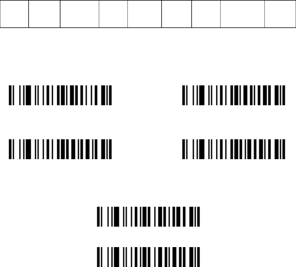
Appendix 2 Parameter bar code
0 %N0 1 %N1
2 3

61
4 5
6 7
8 9
A B
C D
E F
Finish Setting

62
Wireless Communication Setting
Unpair the scanner from host
Unpair the scanner from host
Pair Scanner with Host
Pairing is the process by which a scanner initiates communication with a
host. The scanner with the Host pairing as follows:
1. Connect the scanner to the Host with the Charging Cable.
3UHVVWKH3DLULQJ%XWWRQ´XQWLOWKH6FDQQHULVVXHGDEHHSEHHSVRXQG
NOTE: A host is able to work with as more as 99 scanners at the same
time.
Clear the Buffer of Scanner
Scan the setting bar code below will clear the bar code data save in the
scanner buffer.
Clear the Buffer of Scanner

63
Wireless Channel
When there are more than one host work in the same Space, every host has
to work in different channel. Channel is set as follows:
1. Open a Notepad or other text editor.
2. Press the "Channel Settings button" to change the channel of a host, and
the channel NO will be displayed in the screen.
Scanner ID
Set the Scanner ID˄2 Digits˗00~99˗00*˅
Add Scanner ID as Prefix
If this item is enabled, the scanner will add its ID as prefix of every
barcode. E.g. When scan the bar code ³´LIWKH,'RIWKHVFDQQHULV
³´DQGWKHRXWSXWEDUFRGHGDWDZLOOEH ³,'´
NOTE: The ID of a scanner can be set manually or assigned by the host
DXWRPDWLFDOO\(YHU\VFDQQHUZRUNZLWKWKHVDPH+RVWFDQ¶WEHZLWKWKH
same ID.
Enable Add Scanner ID as Prefix Disable Add Scanner ID as Prefix *

64
Power off Interval
Power Off Interval˄2 Digits˗00~99seconds˗15seconds*˅4
Shut down the Scanner Immediately
RF operating mode:
Auto-Store Mode:
The scanner starts storing barcode data when it loses its connection to a host
(for example, when a user holding the scanner walks out of range). Data
transmission is triggered by reestablishing the connection with hsot (for
example, when a user holding the scanner walks back into range).
Auto-Store Mode*

65
NO-Store Mode:
Do not batch data. The scanner attempts to transmit every scanned barcode.
If the transmission is failed, the barcode data is ignored and issued a "beep
EHHSEHHS´VRXQG
NO-Store Mode
Manual Transmission Mode : Data transmission is triggered by scanning
³Start transfer Bar Code Data´
Manual Transmission Mode
Start transfer Bar Code Data (for Manual Transmission Mode)
Wireless Communication Inter-character delay

66
Scan Wireless Communication Inter-character delay˄2 Digits˗
0.0~9.9seconds˗0.5seconds*˅
Battery Status
*Scan the barcodeˈthe battery status will display on your
screen.
67
FCC Statement
Changes or modifications not expressly approved by the party responsible for
compliance could void the user's authority to operate the equipment.
This equipment has been tested and found to comply with the limits for a Class B
digital device, pursuant to Part 15 of the FCC Rules. These limits are designed
to provide reasonable protection against harmful interference in a residential
installation. This equipment generates uses and can radiate radio frequency
energy and, if not installed and used in accordance with the instructions, may
cause harmful interference to radio communications. However, there is no
guarantee that interference will not occur in a particular installation. If this
equipment does cause harmful interference to radio or television reception, which
can be determined by turning the equipment off and on, the user is encouraged to
try to correct the interference by one or more of the following measures:
-- Reorient or relocate the receiving antenna.
-- Increase the separation between the equipment and receiver.
-- Connect the equipment into an outlet on a circuit different from that to which the
receiver is connected.
-- Consult the dealer or an experienced radio/TV technician for help
This device complies with part 15 of the FCC rules. Operation is subject to the
following two conditions (1)this device may not cause harmful interference, and (2)
this device must accept any interference received, including interference that may
cause undesired operation