Feig Electronic CPR02 Inductive Tag Reader User Manual Sicherheits und Warnhinweise
Feig Electronic GmbH Inductive Tag Reader Sicherheits und Warnhinweise
UserManual.wiki
>
Feig Electronic
>
CPR02 User Manual
Users Manual
Navigation menu
Upload a User Manual
Namespaces
Wiki Guide
HTML
PDF
Info
Views
User Manual
Discussion / Help
Navigation

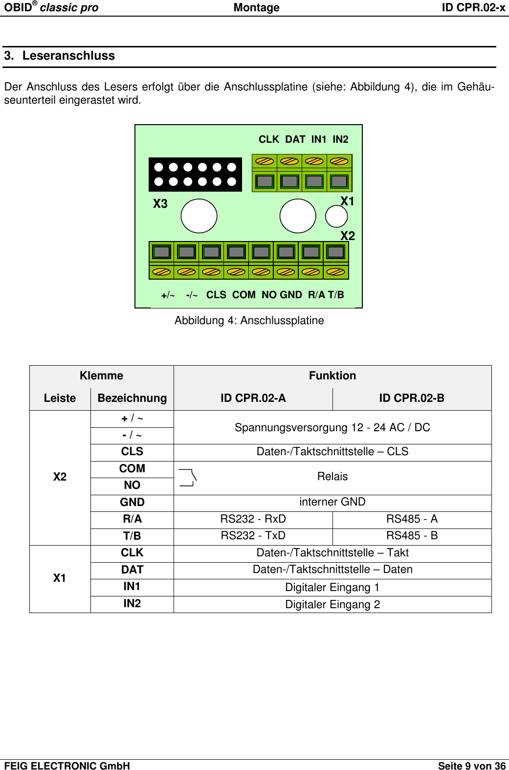
![OBID® classic pro Montage ID CPR.02-xFEIG ELECTRONIC GmbH Seite 11 von 363.2 SpannungsversorgungDie Spannungsversorgung erfolgt über die Klemmen [+ / ~] und [- / ~]. Das Gerät kann wahlweisemit 12 - 24 V AC oder DC versorgt werden. Die Polarität bei DC Spannungsversorgung kann freigewählt werden.HINWEIS:Die Zuleitung sollte nicht direkt parallel mit anderen Energieversorgungs- und Niederspan-nungsleitungen verlegt werden.3.3 RelaisDer Leser verfügt über ein Relais mit einem Schließerkontakt. Der Anschluss erfolgt über dieKlemmen [NO] und [COM].3.4 Digitale EingängeDie beiden digitalen Eingänge [IN1] bzw. [IN2] dürfen nur gegen intern GND, Klemme [GND] ge-schaltet werden (siehe Abbildung 6).Eine Beschaltung mit Fremdspannung kann zur Zerstörung des Gerätes führen!Abbildung 6: Anschluss der digitalen Eingänge3.5 RS232-Schnittstelle (ID CPR.02-A)Leser mit RS232-Schnittstelle werden gem. Abbildung 7 mit dem Leitrechner verbunden.Abbildung 7: Anschluss der RS232-SchnittstelleHostR/AT/BGND ID CPR.02-ARxDTxDGNDIN1IN2GND](https://usermanual.wiki/Feig-Electronic/CPR02/User-Guide-289177-Page-11.png)


![OBID® classic pro Installation ID CPR.02-xPage 28 of 36 FEIG ELECTRONIC GmbH3.2 Power supplyThe power supply is effected via the connectors [+ / ~] and [- / ~]. The device may be suppliedeither with 12 - 24 V AC or DC. In case of DC supply, the polarity may be chosen freely.NOTE:The lead-in wire should not be laid directly parallel to other power supply- and low voltagewires.3.3 RelayThe device is equipped with an relay (normally open contact). The connection is executed via theconnectors [NO] and [COM].3.4 Digital inputs (IN1 / IN2)The digital inputs [IN1] and [IN2] can only be connected to "intern GND" (see Fig 6).Any connection to external voltage might damage the unit!Fig 6: connection of the digital inputs3.5 RS232 Interface (ID CPR.02-A)Readers with RS232 interface have to be connected to the host according to Fig 7.Fig 7: connection of the RS232 InterfaceIN1IN2GNDHostR/AT/BGND ID CPR.02-ARxDTxDGND](https://usermanual.wiki/Feig-Electronic/CPR02/User-Guide-289177-Page-28.png)