Feig Electronic CPR02 Inductive Tag Reader User Manual Sicherheits und Warnhinweise
Feig Electronic GmbH Inductive Tag Reader Sicherheits und Warnhinweise
Users Manual
MONTAGE
INSTALLATION
preliminary
public (B)
2002-09-13
M10701-1de-ID-B.doc
OBID® classic
p
ro
ID CPR.02-A (RS232 Interface)
ID CPR.02-B (RS485 Interface)
(deutsch / english)


OBID® classic pro Montage ID CPR.02-x
FEIG ELECTRONIC GmbH Seite 3 von 36
Hinweis
Copyright 1999 - 2002 by
FEIG ELECTRONIC GmbH
Lange Straße 4
D-35781 Weilburg-Waldhausen
Tel.: +49 6471 3109-0
http://www.feig.de
Alle früheren Ausgaben verlieren mit dieser Ausgabe ihre Gültigkeit.
Die Angaben in diesem Handbuch können ohne vorherige Ankündigung geändert werden.
Weitergabe sowie Vervielfältigung dieses Dokuments, Verwertung und Mitteilung ihres Inhalts sind nicht ge-
stattet, soweit nicht ausdrücklich zugestanden. Zuwiderhandlung verpflichtet zu Schadenersatz. Alle Rechte
für den Fall der Patenterteilung oder Gebrauchsmuster-Eintragung vorbehalten.
Die Zusammenstellung der Informationen in diesem Dokument erfolgt nach bestem Wissen und Gewissen.
FEIG ELECTRONIC GmbH übernimmt keine Gewährleistung für die Richtigkeit und Vollständigkeit der An-
gaben in diesem Dokument. Insbesondere kann FEIG ELECTRONIC GmbH nicht für Folgeschäden auf
Grund fehlerhafter oder unvollständiger Angaben haftbar gemacht werden. Da sich Fehler, trotz aller Bemü-
hungen nie vollständig vermeiden lassen, sind wir für Hinweise jederzeit dankbar.
Die in diesem Dokument gemachten Installationsempfehlungen gehen von günstigsten Rahmenbedingungen
aus. FEIG ELECTRONIC GmbH übernimmt keine Gewähr für die einwandfreie Funktion in systemfremden
Umgebungen.
FEIG ELECTRONIC GmbH übernimmt keine Gewährleistung dafür, dass die in diesem Dokument enthalten-
den Informationen frei von fremden Schutzrechten sind. FEIG ELECTRONIC GmbH erteilt mit diesem Do-
kument keine Lizenzen auf eigene oder fremde Patente oder andere Schutzrechte.
OBID® ist ein eingetragenes Warenzeichen der FEIG ELECTRONIC GmbH
Allgemeine Hinweise zu diesem Dokument
Das Zeichen „!“ weist auf Erweiterungen bzw. Änderungen gegenüber der Vorgängerversion hin.

OBID® classic pro Montage ID CPR.02-x
Seite 4 von 36 FEIG ELECTRONIC GmbH
D E U T S C H
Inhalt
1. Sicherheits- und Warnhinweise 5
2. Montage 6
2.1 Montage auf Unterputzdose....................................................................................... 7
2.2 Montage mit Aufputzrahmen ID APR-A..................................................................... 8
3. Leseranschluss 9
3.1 Jumper und Schalter................................................................................................ 10
3.2 Spannungsversorgung............................................................................................. 11
3.3 Relais......................................................................................................................... 11
3.4 Digitale Eingänge ..................................................................................................... 11
3.5 RS232-Schnittstelle (ID CPR.02-A) .......................................................................... 11
3.6 RS485-Schnittstelle (ID CPR.02-B).......................................................................... 12
3.7 Daten-/Taktschnittstelle ........................................................................................... 13
4. Inbetriebnahme 14
4.1 Adresseinstellung (Busbetrieb mit RS485-Schnittstelle) ...................................... 14
5. Technische Daten 15
5.1 Zulassung ................................................................................................................. 16
5.2 Abmessungen Unterputzmontage........................................................................... 17
5.3 Abmessungen mit ID APR-A bei Aufputzmontage ................................................. 18
6. Lieferumfang: 19
6.1 Optionales Zubehör.................................................................................................. 19

OBID® classic pro Montage ID CPR.02-x
FEIG ELECTRONIC GmbH Seite 5 von 36
1. Sicherheits- und Warnhinweise
• Das Gerät darf nur für den vom Hersteller vorgesehenen Zweck verwendet werden.
• Die Bedienungsanleitung ist zugriffsfähig aufzubewahren und jedem Benutzer auszu-
händigen.
• Unzulässige Veränderungen und die Verwendung von Ersatzteilen und Zusatzeinrich-
tungen, die nicht vom Hersteller des Gerätes verkauft oder empfohlen werden, können
Brände, elektrische Schläge und Verletzungen verursachen. Solche Maßnahmen führen
daher zu einem Ausschluss der Haftung und der Hersteller übernimmt keine Gewährlei-
stung.
• Für das Gerät gelten die Gewährleistungsbestimmungen des Herstellers in der zum
Zeitpunkt des Kaufs gültigen Fassung. Für eine ungeeignete, falsche manuelle oder au-
tomatische Einstellung von Parametern für ein Gerät bzw. ungeeignete Verwendung ei-
nes Gerätes wird keine Haftung übernommen.
• Reparaturen dürfen nur vom Hersteller durchgeführt werden.
• Anschluss-, Inbetriebnahme-, Wartungs-, und sonstige Arbeiten am Gerät dürfen nur
von Elektrofachkräften mit einschlägiger Ausbildung erfolgen.
• Vor dem Öffnen des Gerätes ist stets die Versorgungsspannung abzuschalten und
durch Nachmessen sicherzustellen, daß das Gerät spannungslos ist. Das Verlöschen
einer Betriebsanzeige ist kein Indikator dafür, daß das Gerät vom Netz getrennt und
spannungslos ist.
• Alle Arbeiten am Gerät und dessen Aufstellung müssen in Übereinstimmung mit den
nationalen elektrischen Bestimmungen und den örtlichen Vorschriften durchgeführt
werden.
• Beim Arbeiten an dem Gerät müssen die jeweils gültigen Sicherheitsvorschriften beach-
tet werden.
• Bei gewaltsamer Entfernung des Lesers kann die Steuerleitung (sofern das Relais be-
nutzt wird) für die Tür/Torsteuerung kurzgeschlossen werden. Hierdurch ist ein unbe-
fugtes Öffnen der/des Tür/Tores möglich.
OBID® classic pro Montage ID CPR.02-x
Seite 6 von 36 FEIG ELECTRONIC GmbH
D E U T S C H
2. Montage
Der Leser ist für die Wandmontage auf 60 mm Unterputzdosen vorgesehen. Für die Aufputzmon-
tage kann das Gehäuseunterteil durch den Aufputzrahmen ID APR-A, der als Zubehör lieferbar ist,
ersetzt werden.
HINWEISE:
• Der Leser sollte nicht direkt auf leitende Materialien wie Metallflächen, Metallgitter (Ar-
mierung) oder metallisierte Oberflächen montiert werden, da diese Flächen eine Redu-
zierung der Lesereichweite bewirken. Der Abstand zu derartigen Flächen sollte minde-
stens 3 cm betragen.
• Ist eine Montage auf einer Metalloberfläche notwendig, kann zur Einhaltung des Min-
destabstandes der Aufputzrahmen ID APR-A eingesetzt werden.
• Der räumliche Abstand zu benachbarten Lesern gleicher Bauart sollte 30 cm nicht un-
terschreiten.
• Vor der endgültigen Installation sollte der geplante Installationsort auf seine Tauglich-
keit geprüft werden.
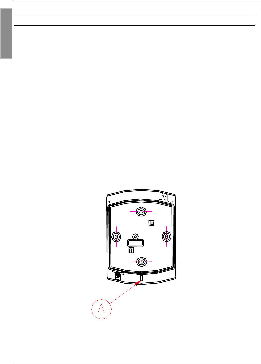
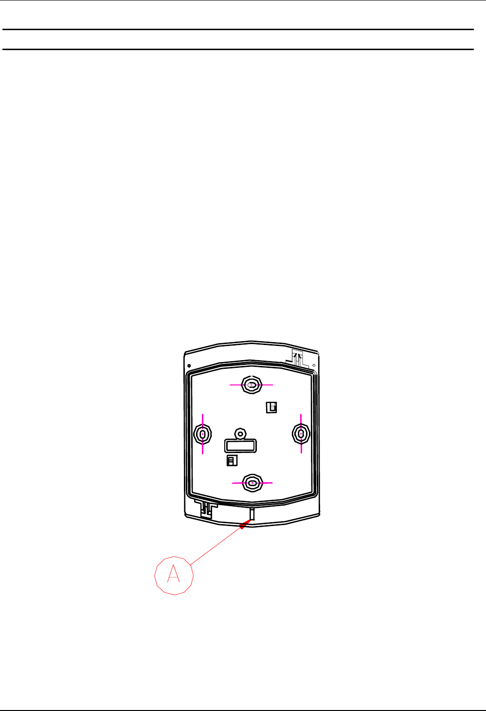
• Die Gehäuseöffnung (A), (siehe Abbildung 1: Montageausrichtung) muß nach unten
montiert werden!
Abbildung 1: Montageausrichtung (A) nach unten

OBID® classic pro Montage ID CPR.02-x
FEIG ELECTRONIC GmbH Seite 7 von 36
2.1 Montage auf Unterputzdose
1. Montageort auswählen:
Die Montage sollte auf einem möglichst ebenen Untergrund erfolgen.
2. Anschluss:
siehe Kapitel Leseranschluss.
3. Inbetriebnahme:
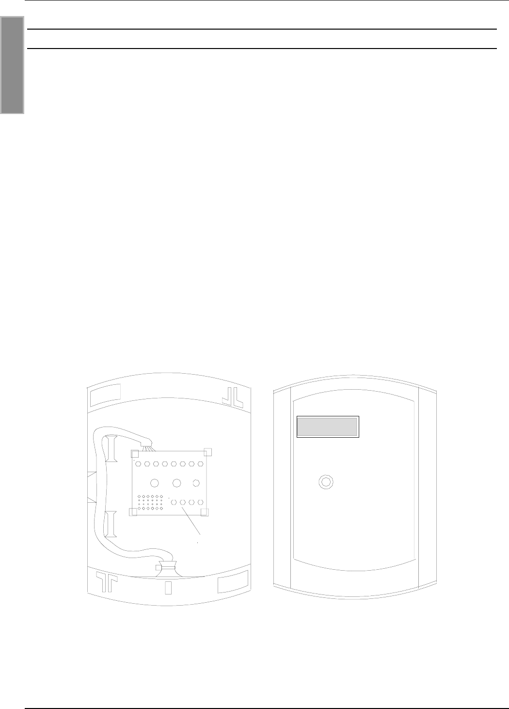
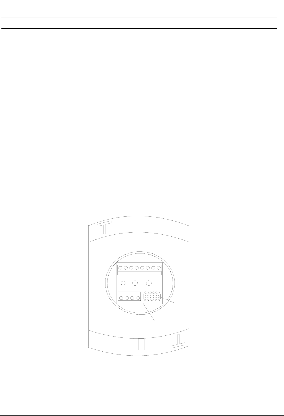
• Anschlussplatine in das Gehäuseunterteil einrasten (siehe: Abbildung 2).
• Gehäuseoberteil auf Gehäuseunterteil stecken. Dabei die Stiftleiste der Leserelektronik sau-
ber in Buchsenleiste X3 einführen!
• siehe Kapitel Inbetriebnahme
4. Wandmontage:
Erst nach Kontrolle der Inbetriebnahmearbeiten sollte die Wandmontage erfolgen.
• Gehäuseoberteil von –Unterteil abziehen.
• Gehäuseunterteil mit eingerasteter Anschlussplatine auf Untergrund verschrauben.
• Gehäuseoberteil auf Gehäuseunterteil stecken. Dabei die Stiftleiste der Leserelektronik sau-
ber in Buchsenleiste X3 einführen!
• Gehäuseoberteil mit Schneidschraube 3,2 x 25 mm auf Gehäuseunterteil verschrauben.
• Frontaufkleber auf das saubere und fettfreie Gehäuse aufkleben.
(1)
X3
Abbildung 2: Rückansicht mit eingerasteter Anschlussplatine (1)
OBID® classic pro Montage ID CPR.02-x
Seite 8 von 36 FEIG ELECTRONIC GmbH
D E U T S C H
2.2 Montage mit Aufputzrahmen ID APR-A
1. Wandmontage:
• Die Montage sollte auf einem möglichst ebenen Untergrund erfolgen.
• Durchbrüche für Zuleitung im Gehäuseunterteil herstellen, ggf. Würgenippel einsetzen und
Zuleitung einziehen.
• Gehäuseunterteil mit Untergrund verschrauben.
2. Anschluss:
siehe Kapitel Leseranschluss.
3. Gehäuse schließen:
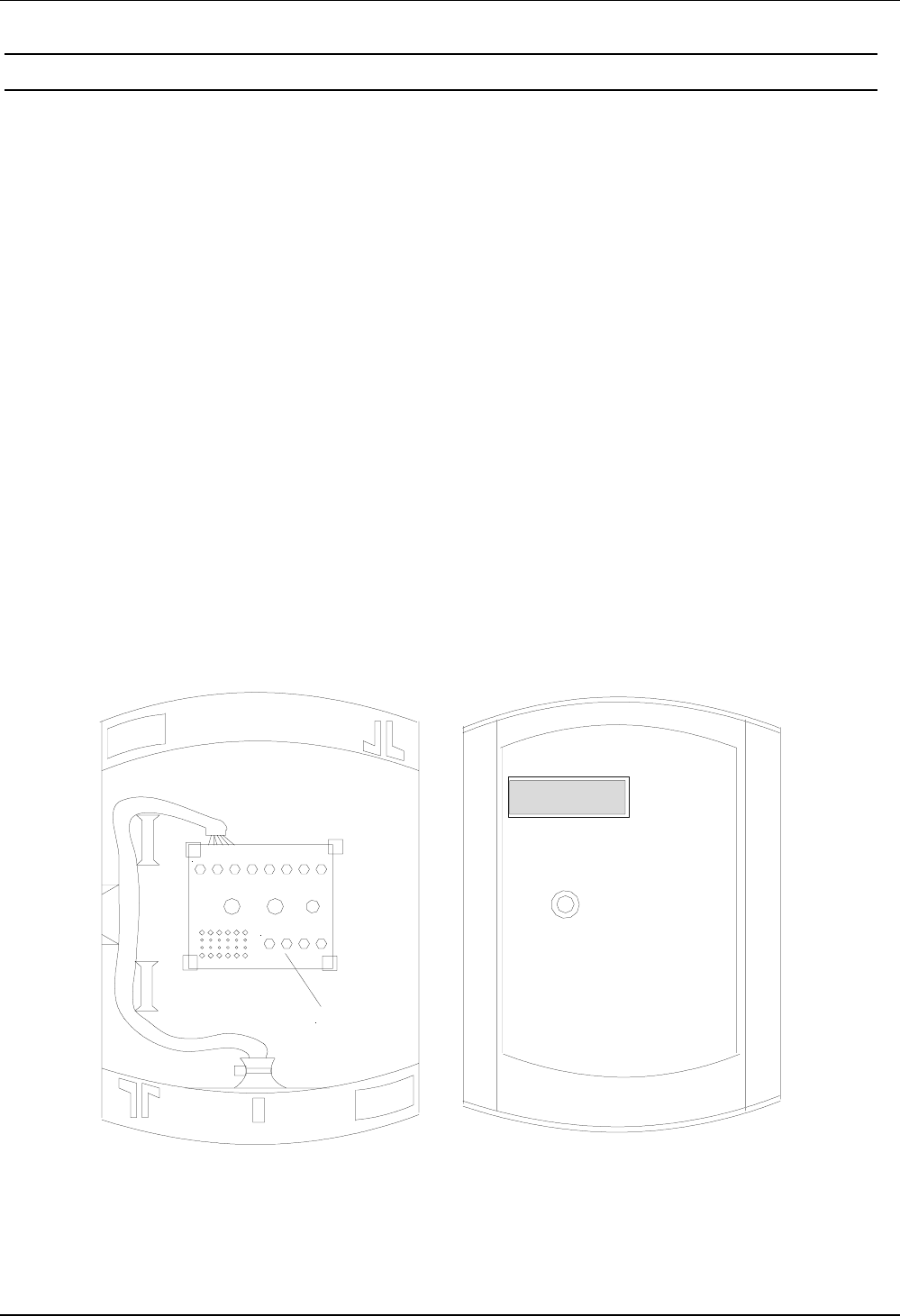
• Anschlussplatine (1) gem. Abbildung 3, mit den Anschlussklemmen nach unten in das Ge-
häuseunterteil einrasten. Dazu die Rasthaken mit den Fingern leicht auseinanderdrücken.
• Gehäuseoberteil auf Gehäuseunterteil stecken. Dabei die Stiftleiste der Leserelektronik sau-
ber in Buchsenleiste X3 einführen!
• Gehäuseoberteil mit Schneidschraube 3,2 x 25 mm mit Gehäuseunterteil verschrauben.
4. Inbetriebnahme:
siehe Kapitel Inbetriebnahme
5. Frontaufkleber aufkleben:
Frontaufkleber auf das saubere und fettfreie Gehäuse aufkleben.
+/~ -/~ R COM NO GND R/A T/B
CLK DAT IN1 IN2
(1)
Abbildung 3: Aufputzmontage (LED oben links)
Offenes Aufputzgehäuses mit eingesetzter Anschlussplatine (1)
OBID® classic pro Montage ID CPR.02-x
FEIG ELECTRONIC GmbH Seite 9 von 36
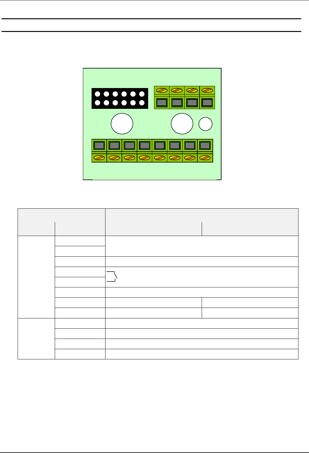
3. Leseranschluss
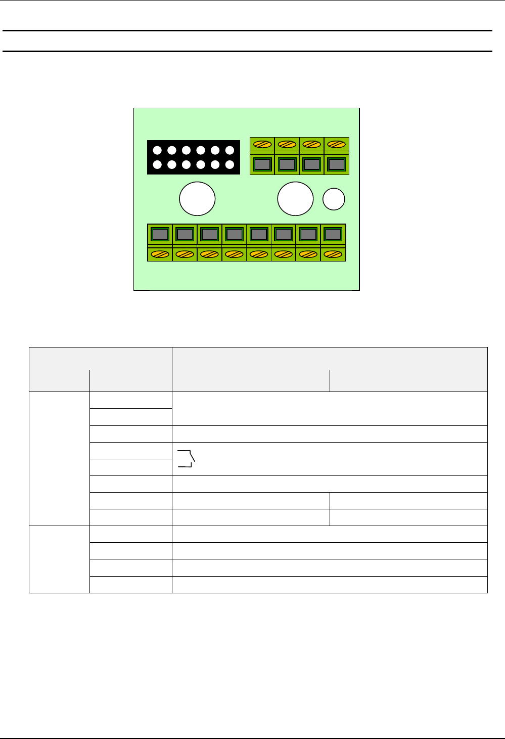
Der Anschluss des Lesers erfolgt über die Anschlussplatine (siehe: Abbildung 4), die im Gehäu-
seunterteil eingerastet wird.
Abbildung 4: Anschlussplatine
Klemme Funktion
Leiste Bezeichnung ID CPR.02-A ID CPR.02-B
+ / ~
- / ~Spannungsversorgung 12 - 24 AC / DC
CLS Daten-/Taktschnittstelle – CLS
COM
NO Relais
GND interner GND
R/A RS232 - RxD RS485 - A
X2
T/B RS232 - TxD RS485 - B
CLK Daten-/Taktschnittstelle – Takt
DAT Daten-/Taktschnittstelle – Daten
IN1 Digitaler Eingang 1
X1
IN2 Digitaler Eingang 2
CLK DAT IN1 IN2
+/~ -/~ CLS COM NO GND R/A T/B
X1
X2
X3
OBID® classic pro Montage ID CPR.02-x
Seite 10 von 36 FEIG ELECTRONIC GmbH
D E U T S C H
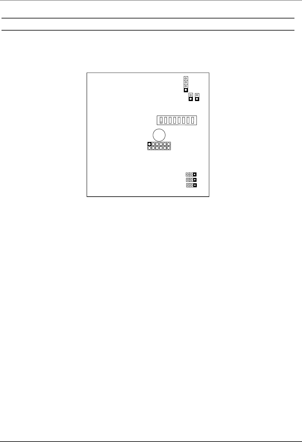
3.1 Jumper und Schalter
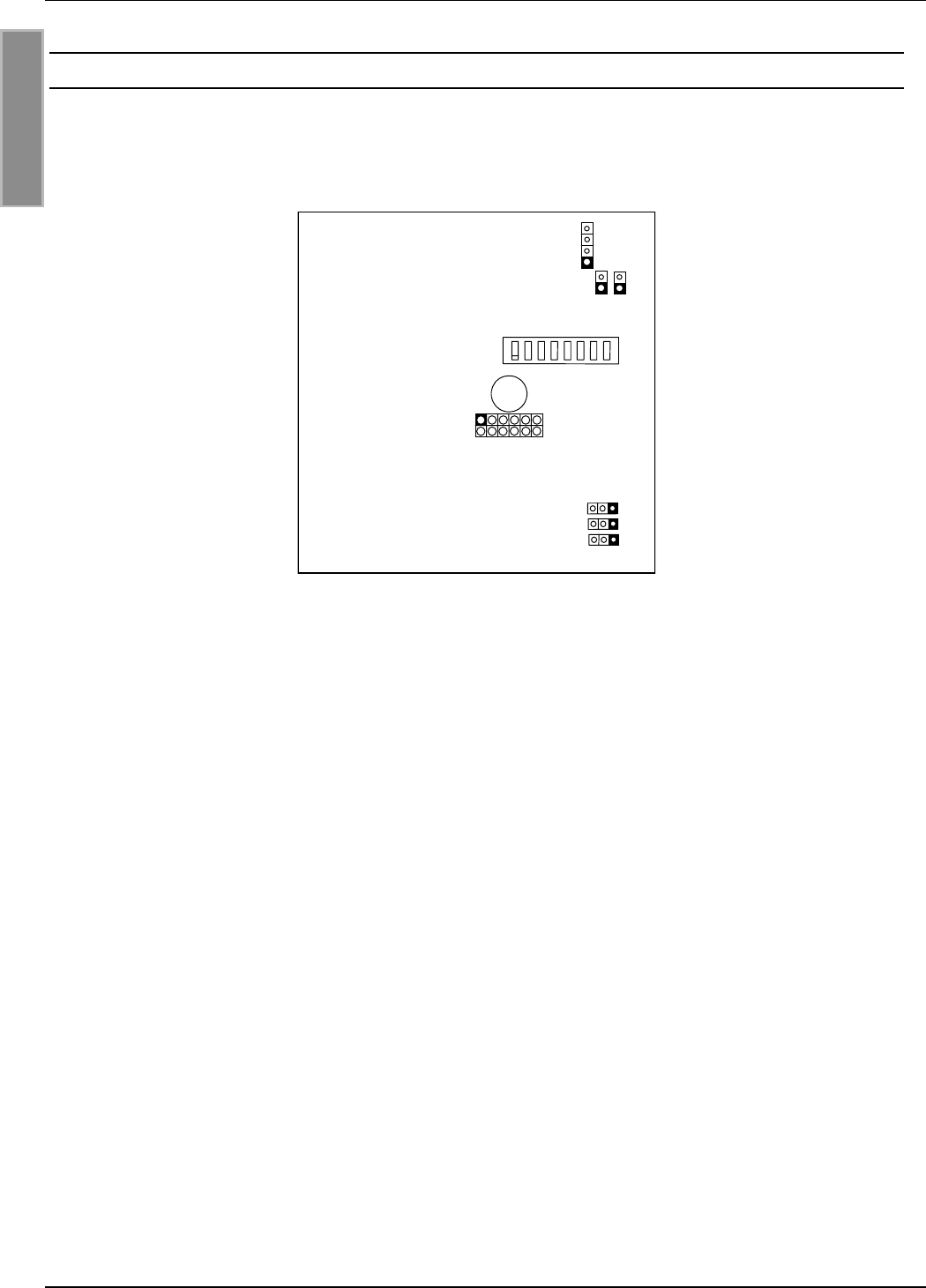
Abbildung 5 zeigt die Lage der Jumper und Schalter auf der Leiterplatte des ID CPR.02-x. Die
Jumper und Schalter sind nur bei demontiertem Gerät zugänglich.
1 2 3 4 5 6 7 8 ON
OFF
X7
1
J1 J2
X1
S1
3 2 1
X4
X3
X2
Abbildung 5: Jumper und Schalter
S1:
DIP-Schalter zur Einstellung der Leseradresse.
X1:
Stiftleiste zum Aufstecken der Anschlussplatine.
X2 / X3 / X4:
Jumper für Abschlusswiderstände der RS485-Schnittstelle (nur ID CPR.02-B).
X7:
Programmierschnittstelle für Firmwareupdate.
J1 / J2:
Jumper für Firmwareupdate.
OBID® classic pro Montage ID CPR.02-x
FEIG ELECTRONIC GmbH Seite 11 von 36
3.2 Spannungsversorgung
Die Spannungsversorgung erfolgt über die Klemmen [+ / ~] und [- / ~]. Das Gerät kann wahlweise
mit 12 - 24 V AC oder DC versorgt werden. Die Polarität bei DC Spannungsversorgung kann frei
gewählt werden.
HINWEIS:
Die Zuleitung sollte nicht direkt parallel mit anderen Energieversorgungs- und Niederspan-
nungsleitungen verlegt werden.
3.3 Relais
Der Leser verfügt über ein Relais mit einem Schließerkontakt. Der Anschluss erfolgt über die
Klemmen [NO] und [COM].
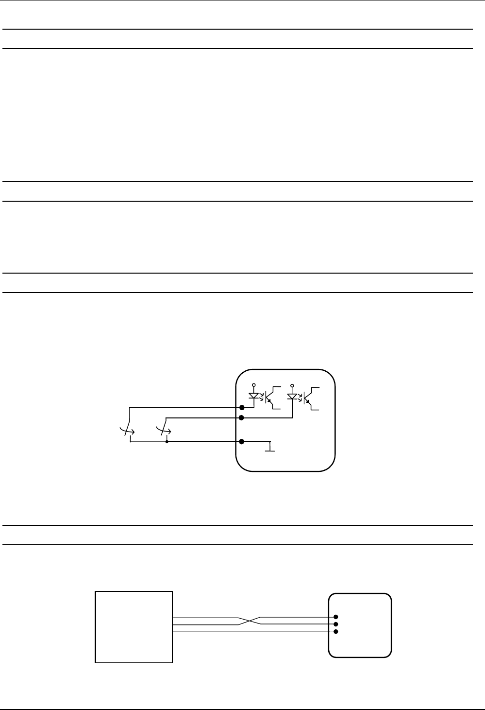
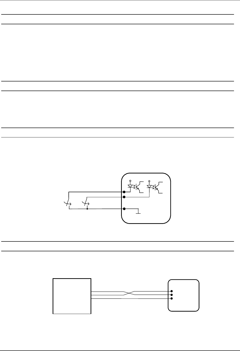
3.4 Digitale Eingänge
Die beiden digitalen Eingänge [IN1] bzw. [IN2] dürfen nur gegen intern GND, Klemme [GND] ge-
schaltet werden (siehe Abbildung 6).
Eine Beschaltung mit Fremdspannung kann zur Zerstörung des Gerätes führen!
Abbildung 6: Anschluss der digitalen Eingänge
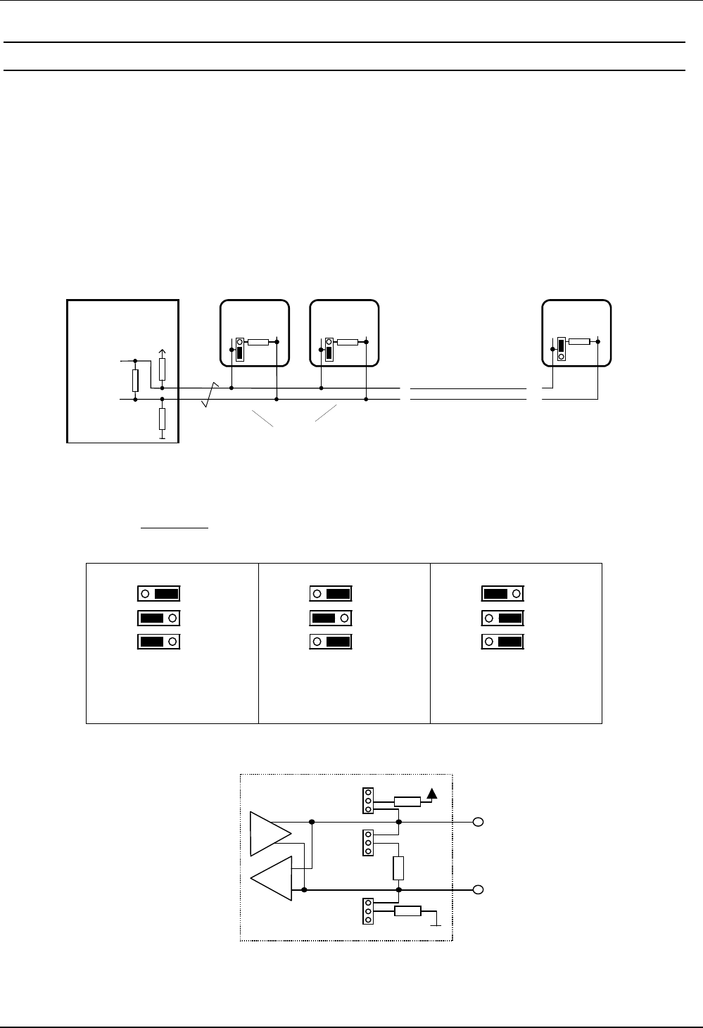
3.5 RS232-Schnittstelle (ID CPR.02-A)
Leser mit RS232-Schnittstelle werden gem. Abbildung 7 mit dem Leitrechner verbunden.
Abbildung 7: Anschluss der RS232-Schnittstelle
Host
R/A
T/B
GND ID CPR.02-A
RxD
TxD
GND
IN1
IN2
GND
OBID® classic pro Montage ID CPR.02-x
Seite 12 von 36 FEIG ELECTRONIC GmbH
D E U T S C H
3.6 RS485-Schnittstelle (ID CPR.02-B)
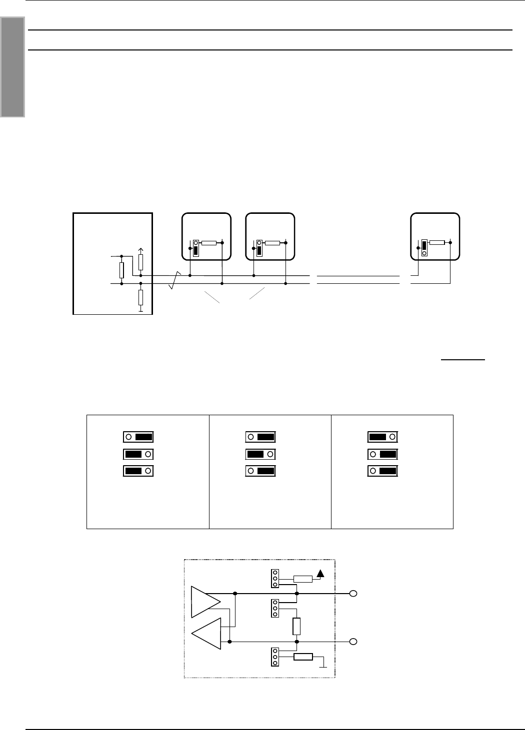
Bei einem RS485-Datenbus kann es notwendig werden Abschlusswiderstände einzusetzen. Die
Notwendigkeit zum Einsatz von Abschlusswiderständen ist für jede Installation im Einzelfall zu
prüfen, da dies z. B. von Leitungslängen, Busaufbau, Spannungsversorgung der Leser und dem
verwendeten Leitrechner abhängig ist. Der Abschlusswiderstand ist i.d.R. nur am Busende, also
am letzten Gerät, notwendig. Dazu ist an der Jumper an X2 Pin 1 und 2 zu stecken, Jumper in
Stellung 1 – 2 (siehe Abbildung 8 und Abbildung 5).
Der Busbetrieb setzt einen Leitrechner mit Abschlusswiderstand und aktiver Terminierung voraus.
Als Leitung wird eine paarweise verseilte oder verdrillte Leitung empfohlen.
Host
ohne Abschlusswiderstand
R/A
T/B
ID CPR.02-B
(mit aktiver Terminierung)
mit Abschlusswiderstand
A
B
X2
ID CPR.02-B
X2
ID CPR.02-B
X2
T/B T/BR/A R/A
Abbildung 8: Busbetrieb mit RS485-Schnittstelle
Steht kein Leitrechner mit aktiver Terminierung zur Verfügung, kann ersatzweise an maximal ei-
nem Leser eine aktive Terminierung vorgenommen werden. Dazu stehen die Jumper X3 und X4
zur Verfügung.
3 2 1
X4
X3
X2
3 2 1
X4
X3
X2
3 2 1
X4
X3
X2
ohne Terminierung
(Werkseinstellung)
Abschlusswiderstand aktive Terminierung u.
Abschlusswiderstand
Abbildung 9: Jumperstellungen RS485-Schnittstelle
Abbildung 10: interne Beschaltung der RS485-Schnittstelle
X2
X
3
X4 +5V
GND
1
T / B
R / A
1
1
1kΩ
1kΩ
100Ω

OBID® classic pro Montage ID CPR.02-x
FEIG ELECTRONIC GmbH Seite 13 von 36
3.7 Daten-/Taktschnittstelle
Der Anschluss der Daten-/Taktschnittstelle erfolgt gem. Abbildung 11. Falls am Host kein CLS
Anschluss vorgesehen oder notwendig ist, kann auf diese Leitung verzichtet werden.
Abbildung 11: Anschluss der Daten-/Taktschnittstelle
Host
ID CPR.02-A
CLOCK
DATA
CLS
GND
CLK
DAT
CLS
GND

OBID® classic pro Montage ID CPR.02-x
Seite 14 von 36 FEIG ELECTRONIC GmbH
D E U T S C H
4. Inbetriebnahme
4.1 Adresseinstellung (Busbetrieb mit RS485-Schnittstelle)
An Lesern mit RS232-Schnittstelle ist i.d.R. keine Adresseinstellung notwendig. Bei Geräten mit
RS485-Schnittstelle kann die Geräteadresse entweder über den DIP-Schalter am geöffneten Ge-
rät (siehe Abbildung 5), oder über den Leitrechner (Host) erfolgen.
Busbetrieb mit bis zu 16 Lesern:
Die Einstellung der Geräteadresse erfolgt mittels der DIP-Schalter S1, DIP1 - DIP4, ge-
mäß Tabelle (DIP5 - DIP8 haben keine Funktion). Dabei wird jeder Leser mit einer indivi-
duellen Adresse versehen.
Adresse DIP 1 DIP 2 DIP 3 DIP 4
0OFF OFF OFF OFF
1ON
OFF OFF OFF
2OFF ON OFF OFF
3ONON
OFF OFF
4OFF OFF ON OFF
5ON
OFF ON OFF
6OFF ON ON OFF
7ONONON
OFF
8OFF OFF OFF ON
9ON
OFF OFF ON
10 OFF ON OFF ON
11 ON ON OFF ON
12 OFF OFF ON ON
13 ON OFF ON ON
14 OFF ON ON ON
15 ON ON ON ON
Busbetrieb mit 16 - 32 Lesern:
Die Adresseinstellung erfolgt per Software über den Leitrechner (Host).
HINWEIS:
Da alle Leser werksseitig die Adresse 0 eingestellt haben, müssen sie nacheinan-
der angeschlossen und konfiguriert werden.

OBID® classic pro Montage ID CPR.02-x
FEIG ELECTRONIC GmbH Seite 15 von 36
5. Technische Daten
Gehäuse Kunststoff ASA
Farbe Gehäuseunterteil:
Gehäuseoberteil: ähnlich RAL 9002 (grauweiß)
ähnlich RAL 7043 (verkehrgrau)
Gewicht ca. 120 g
Schutzart IP 54
Spannungsversorgung 12 - 24 V AC/DC
Leistungsaufnahme max. 2,6 W
Temperaturbereich -25°C bis 60°C
relative Luftfeuchte 95 % (nicht betauend)
Antenne integriert
Trägerfrequenz 13,56 MHz
unterstützte Transpondertypen • nach ISO14443-A
• nach ISO14443-B
• nach ISO15693
• I-CODE1
Signalgeber 1 x Bicolor-LED (rot, grün, orange)
1 x Summer
Relais 1 x Schließer
Kontaktbelastbarkeit: 24 V AC/DC 1,5 A
digitale Eingänge 2 x konfigurierbar
Leitungslänge max. 3 m
Schnittstellen: asynchron (bidirektional) 4800 bis 38400 Baud
• RS232 (ID CPR.02-A)
Leitungslänge max. 10 m
• RS485 (ID CPR.02-B)
max. 32 Geräte pro Datenbus
Daten-/Takt (unidirektional) TTL
Leitungslänge max. 3 m
• Magnetkarten-Emulation,
Spur 1 (7 Bit) u. Spur 2+3 (5 Bit)
• Wiegand-Emulation
DIP-Schalter 8-polig
EEPROM 10.000 Schreibzyklen
Werkskonfiguration:
asynchrone Schnittstelle: 9600 Baud, 8 Daten- 1 Stoppbit, even Parity
IN1 aktiviert LED rot und das Relais
IN2 aktiviert LED grün und den Summer
LED-Betriebsanzeige orange

OBID® classic pro Montage ID CPR.02-x
Seite 16 von 36 FEIG ELECTRONIC GmbH
D E U T S C H
5.1 Zulassung
Die Funkanlage entspricht, bei bestimmungsgemäßer Verwendung den grundlegenden Anforde-
rungen des Artikels 3 und den übrigen einschlägigen Bestimmungen der R&TTE Richtlinie
1999/5/E6 vom März 99.
OBID® classic pro Montage ID CPR.02-x
FEIG ELECTRONIC GmbH Seite 17 von 36
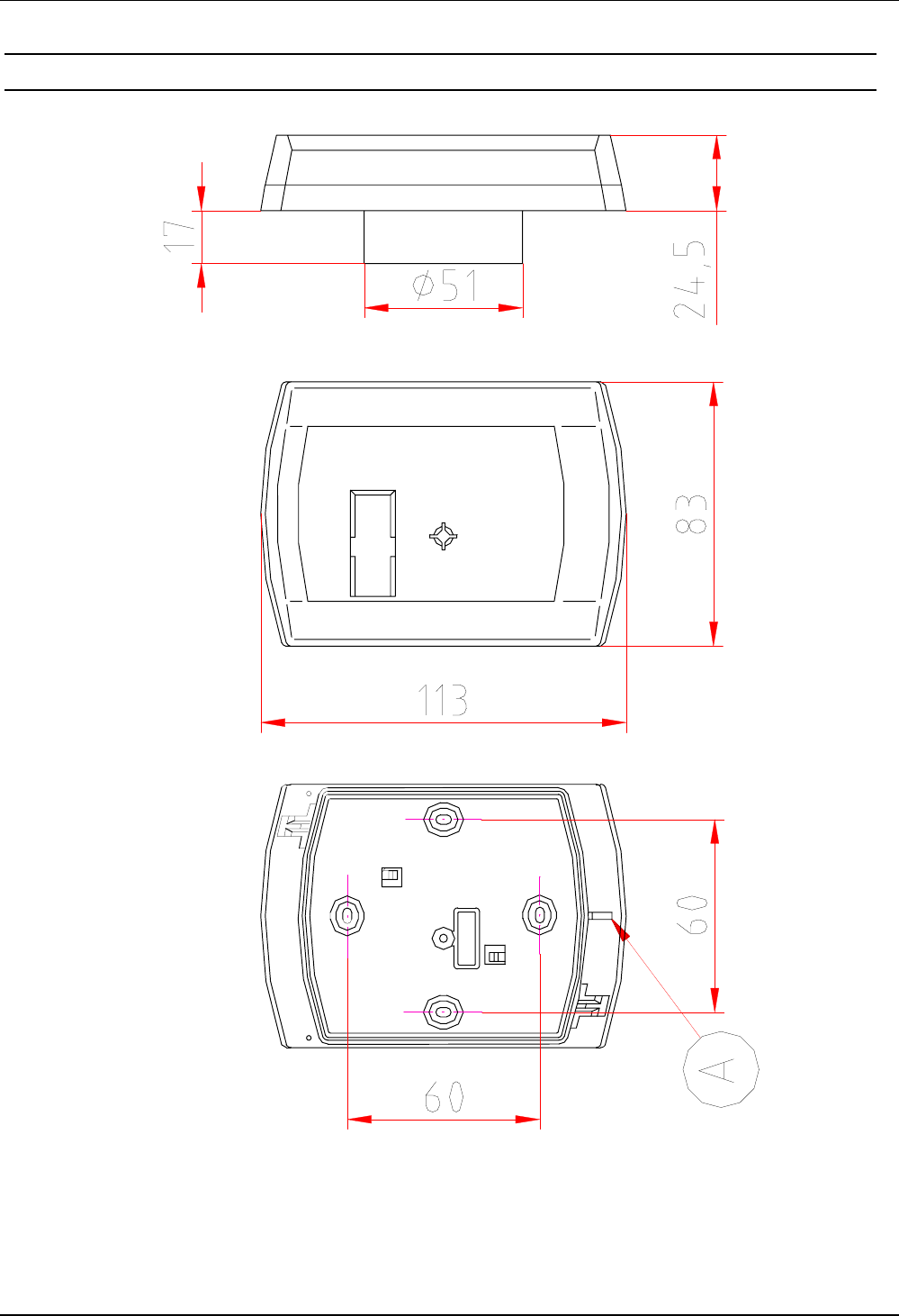
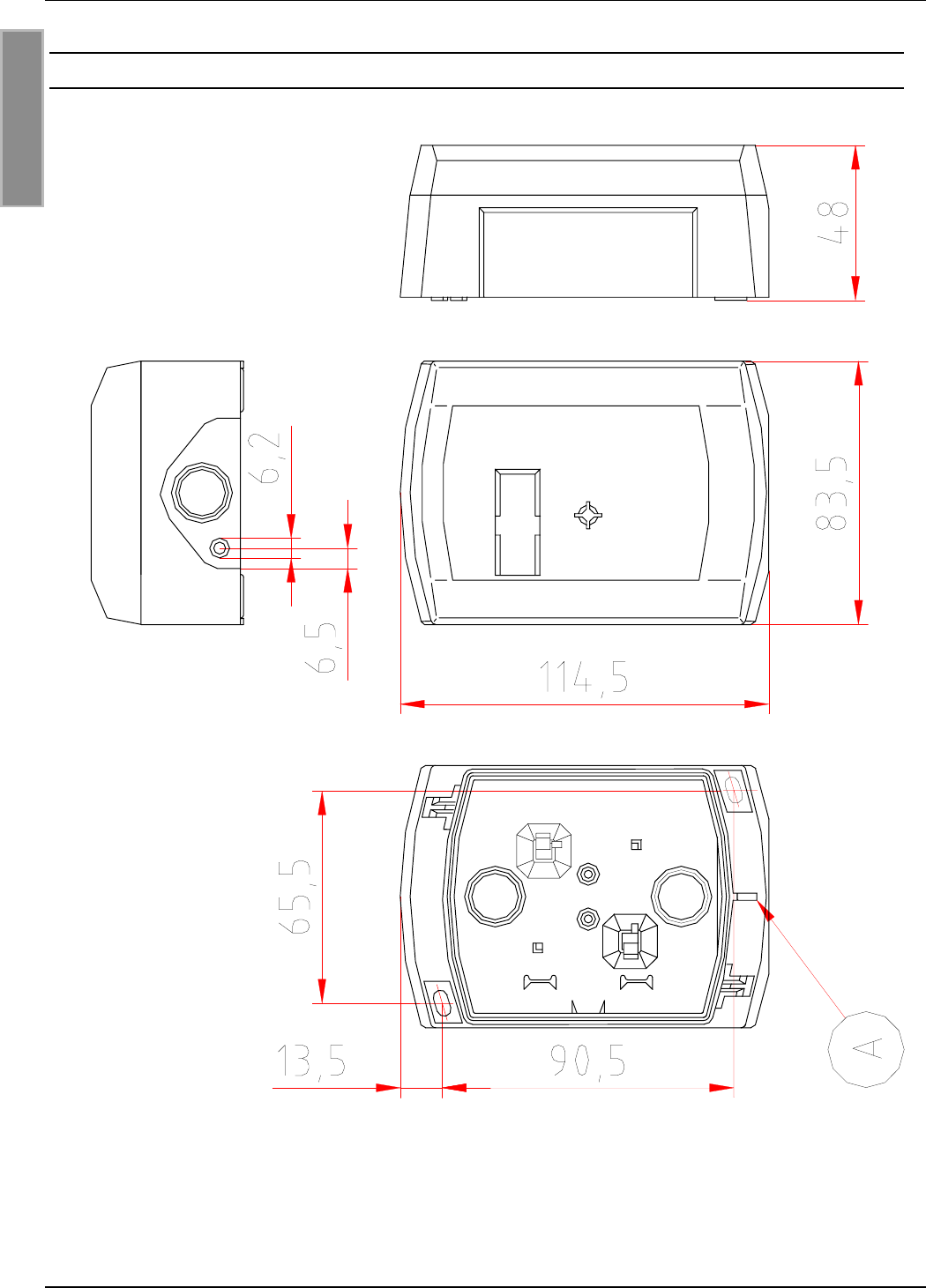
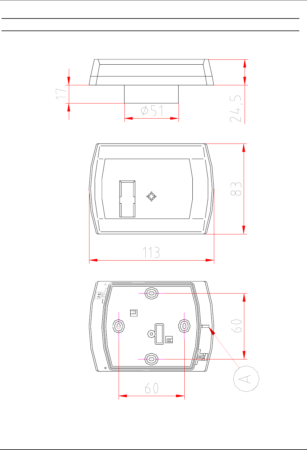
5.2 Abmessungen Unterputzmontage
Abbildung 12: Abmessungen Unterputzgehäuse
(A) = Unten
OBID® classic pro Montage ID CPR.02-x
Seite 18 von 36 FEIG ELECTRONIC GmbH
D E U T S C H
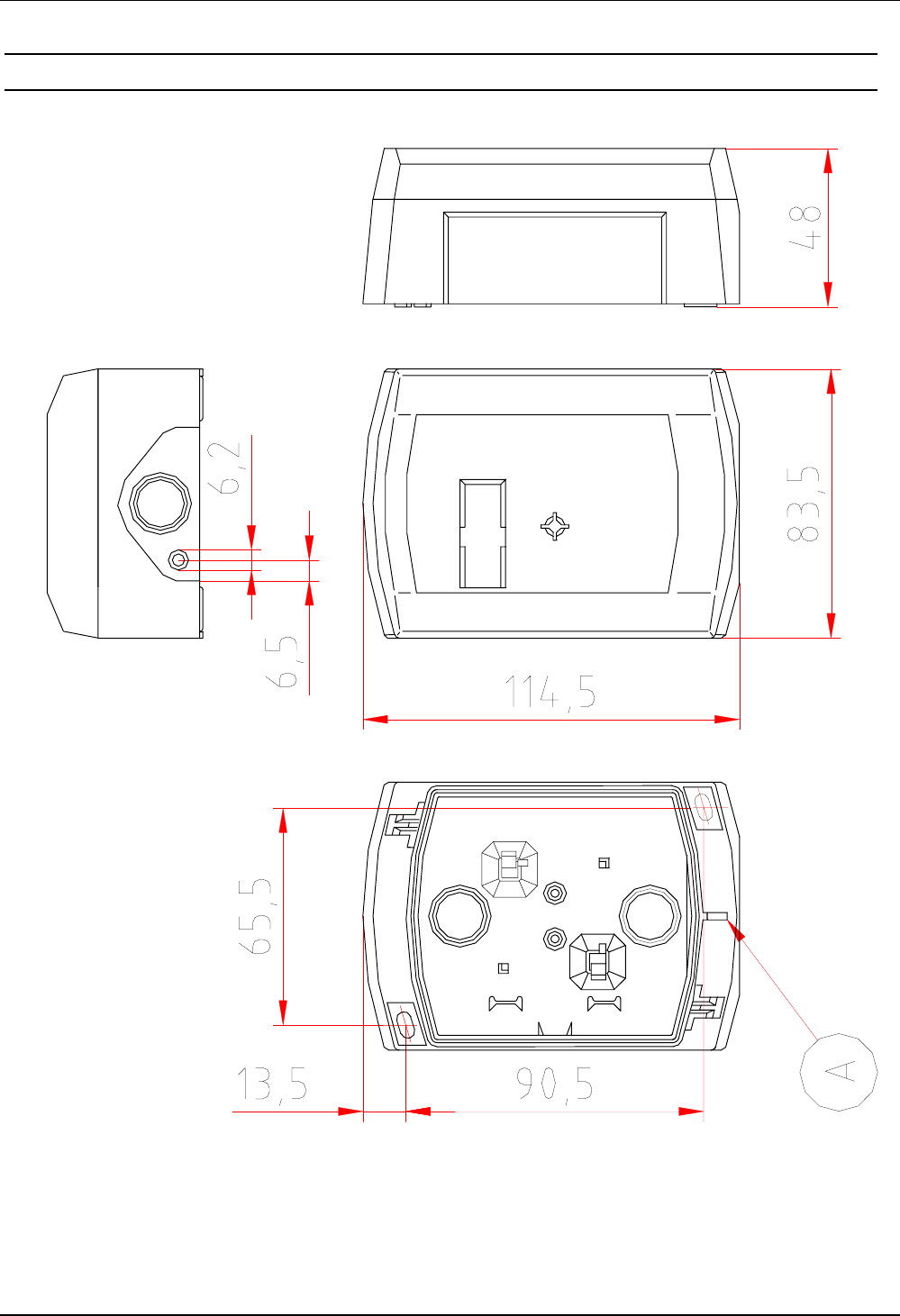
5.3 Abmessungen mit ID APR-A bei Aufputzmontage
Abbildung 13: Abmessungen bei Montage
mit Aufputzrahmen ID APR-A
(A) = Unten

OBID® classic pro Montage ID CPR.02-x
FEIG ELECTRONIC GmbH Seite 19 von 36
6. Lieferumfang:
1 x Gehäuseunterteil (Unterputzgehäuse)
1 x Gehäuseoberteil mit Leserelektronik
1 x Anschlussplatine
1 x Frontaufkleber
1 x Schneidschraube 3,2 x 25 mm (zur Verbindung der Gehäuseteile)
2 x Schneidschrauben 3,2 x 15 mm (zur Wandmontage)
1 x Montageanleitung
6.1 Optionales Zubehör
Gehäuseunterteil für Aufputzmontage
ID APR-A Bestell-Nr.: 1144.001.00
Frontaufkleber
ID AKL.02 Frontaufkleber Bestell-Nr.: 1424.000.00

OBID® classic pro Installation ID CPR.02-x
Page 20 of 36 FEIG ELECTRONIC GmbH
Note
Copyright 1999 - 2002 by
FEIG ELECTRONIC GmbH
Lange Strasse 4
D-35781 Weilburg-Waldhausen
Tel.: +49 6471 3109-0
http://www.feig.de
With the edition of this document, all previous editions become void. Indications made in this manual may be
changed without previous notice.
Copying of this document, and giving it to others and the use or communication of the contents thereof are
forbidden without express authority. Offenders are liable to the payment of damages. All rights are reserved
in the event of the grant of a patent or the registration of a utility model or design.
Composition of the information in this document has been done to the best of our knowledge. FEIG ELEC-
TRONIC GmbH does not guarantee the correctness and completeness of the details given in this manual
and may not be held liable for damages ensuing from incorrect or incomplete information. Since, despite all
our efforts, errors may not be completely avoided, we are always grateful for your useful tips.
The instructions given in this manual are based on advantageous boundary conditions. FEIG ELECTRONIC
GmbH does not give any guarantee promise for perfect function in cross environments.
FEIG ELECTRONIC GmbH assumes no responsibility for the use of any information contained in this
document and makes no representation that they free of patent infringement. FEIG ELECTRONIC GmbH
does not convey any license under its patent rights nor the rights of others.
OBID® is registered trademark of FEIG ELECTRONIC GmbH.
General information's regarding this document
The sign "!" indicates extensions or changes of this manual compared with the former issue.

OBID® classic pro Installation ID CPR.02-x
FEIG ELECTRONIC GmbH Page 21 of 36
Content
1. Safety instructions – please read carefully prior to initiation 22
2. Installation 23
2.1 Installation on flush-mounting box......................................................................... 24
2.2 Installation with surface frame ID APR-A................................................................ 25
3. Reader-connection 26
3.1 Jumper and Switches............................................................................................... 27
3.2 Power supply ............................................................................................................ 28
3.3 Relay.......................................................................................................................... 28
3.4 Digital inputs (IN1 / IN2) ........................................................................................... 28
3.5 RS232 Interface (ID CPR.02-A)................................................................................. 28
3.6 RS485 Interface (ID CPR.02-B)................................................................................. 29
3.7 Data-/Clock interface................................................................................................ 30
4. Operation 31
4.1 Address setting (Bus mode with RS485 interface) ................................................ 31
5. Technical data 32
5.1 Approval.................................................................................................................... 33
5.2 Dimensions for concealed installation ................................................................... 34
5.3 Dimensions for surface installation with ID APR-A ............................................... 35
6. System delivery contents: 36
6.1 Optional Accessories ............................................................................................... 36

OBID® classic pro Installation ID CPR.02-x
Page 22 of 36 FEIG ELECTRONIC GmbH
1. Safety instructions – please read carefully prior to initiation
• The device has to be used only for the purpose designed by the manufacturer.
• The operation manual has to be stored available at any time and has to be handed over
to each user.
• Unauthorized changes and the use of spare parts and additional devices which have not
been sold or recommended by the manufacturer may cause fire, electric shocks or
injuries. Such measures will lead to exclusion of any liability by the manufacturer.
• The liability-prescriptions of the manufacturer in the issue valid at the time of purchase
are valid for the device. The manufacturer is not legally responsible for incorrect,
unsuitable manual or automatical setting of parameters for a device or the incorrect
application of a device.
• Repairs can only be executed by the manufacturer.
• Installation-, operation- and maintenance procedures should only be carried out by
qualified personnel.
• Before opening the device, the power supply must always be interrupted. Make sure
that the device is without voltage by measuring. CAUTION! The fading of an operation
control (LED) is no indicator for an interrupted power supply or the device being
without voltage!
• Works at the device and its installation have to be executed according to the national
legal requirements and local prescriptions.
• When working on devices the valid safety regulations must be observed.
• Caution:
Any modification to the equpment not expressively authorized by the party responsible
for compliance could void the users authority to operate the equipment.
OBID® classic pro Installation ID CPR.02-x
FEIG ELECTRONIC GmbH Page 23 of 36
2. Installation
The Reader has been designed for wall installation on 60 mm flush-mounting box. For surface
installation, the bottom part of the casing can be substituted by the surface frame ID APR-A, which
is available as an attachment.
NOTES:
• The Reader must not be installed directly upon conductive materials as e.g. metal sur-
faces, metal grids (reinforcements) or metallized surfaces, as these surfaces reduce the
detection range of the Reader. The distance between the Reader and such surfaces
should be min. 3 cm.
If an installation to a metal surface becomes necessary, the surface frame ID APR-A can
be employed in order to keep the minimal distance.
• The distance between two Readers of the same type should not fall below 30 cm.
• Before any installation the intended position of the Reader should be tested for its suit-
ability.
• The opening (A) in the casing (see Fig 1) has to be installed downwards!
Fig 1: mounting direction (A) downwards
OBID® classic pro Installation ID CPR.02-x
Page 24 of 36 FEIG ELECTRONIC GmbH
2.1 Installation on flush-mounting box
1. Select installation place:
The installation should be executed always on a surface as even as possible.
2. Connection:
see chapter Reader-connection
3. Operation:
• snap connection board into bottom part of casing (see Fig 2).
• Put the top of the casing onto its bottom part. The pin board of the Reader electronic has to
be inserted carefully into the socket board X3!
• see chapter Installation
4. Wall installation:
The wall installation should be executed only after a control of all functions.
• Remove top of the casing from its bottom part.
• Screw bottom part of casing with snapped-in connection board to selected surface.
• Put top of the casing again onto its bottom part. Insert the pin board of the Reader electronic
carefully in the socket board X3!
• Screw top of casing to bottom part by using thread cutting screw 3,2 x 25 mm.
• Attach adhesive label to clean and non-greasy casing.
(1)
X3
Fig 2: Rear view with snapped-in connection board (1)
OBID® classic pro Installation ID CPR.02-x
FEIG ELECTRONIC GmbH Page 25 of 36
2.2 Installation with surface frame ID APR-A
1. Wall installation:
• The installation should be executed always on a surface as even as possible.
• Make openings into the bottom part of the casing for lead-in wire, eventually attach twisting
sleeve and pull wire into the casing.
• Screw bottom part of casing to surface.
2. Connection:
see chapter Reader-connection
3. Close casing:
• Snap-in connection board (1) to bottom part of casing according to Fig 3 with the connectors
in downward direction. In order to do this, press the notches slightly apart with your fingers.
• Put top of the casing onto its bottom part. Insert the pin board of the Reader electronic
carefully into the socket board X3!!
• Screw top of casing to bottom part by using thread cutting screw 3,2 x 25 mm.
4. Operation:
see chapter Reader-connection
5. Adhesive label:
Attach label to clean and non-greasy casing
+/~ -/~ R COM NO GND R/A T/B
CLK DAT IN1 IN2
(1)
Fig 3: Surface installation (LED top left)
Open surface casing with snapped-in connection board (1)
OBID® classic pro Installation ID CPR.02-x
Page 26 of 36 FEIG ELECTRONIC GmbH
3. Reader-connection
The connection of the Reader is executed via the connection board. (see: Fig 4) which is snapped
into the bottom part of the casing.
Fig 4: Connection board
connector function
board name ID CPR.02-A ID CPR.02-B
+ / ~
- / ~power supply 12 - 24 AC / DC
CLS data-/clock interface – cls
COM
NO relay
GND internal GND
R/A RS232 - RxD RS485 - A
X2
T/B RS232 - TxD RS485 - B
CLK data-/clock interface – clock
DAT data-/clock interface – data
IN1 digital input 1 (IN1)
X1
IN2 digital input 2 (IN1)
Table 1: connection plan
CLK DAT IN1 IN2
+/~ -/~ CLS COM NO GND R/A T/B
X1
X2
X3
OBID® classic pro Installation ID CPR.02-x
FEIG ELECTRONIC GmbH Page 27 of 36
3.1 Jumper and Switches
Fig 5 shows the position of the jumpers and switches on the printed circuit board of the
ID CPR.02-x. The jumpers and switches are only accessible at the opened device.
1 2 3 4 5 6 7 8 ON
OFF
X7
1
J1 J2
X1
S1
3 2 1
X4
X3
X2
Fig 5: Jumper and Switches
S1:
DIP-switch to configure the Reader address.
X1:
Terminal for sticking up the connection board.
X2 / X3 / X4:
Jumper for termination resistors of the RS485 interface (only ID CPR.02-B).
X7:
Interface for firmware update.
J1 / J2:
Jumper for firmware update.
OBID® classic pro Installation ID CPR.02-x
Page 28 of 36 FEIG ELECTRONIC GmbH
3.2 Power supply
The power supply is effected via the connectors [+ / ~] and [- / ~]. The device may be supplied
either with 12 - 24 V AC or DC. In case of DC supply, the polarity may be chosen freely.
NOTE:
The lead-in wire should not be laid directly parallel to other power supply- and low voltage
wires.
3.3 Relay
The device is equipped with an relay (normally open contact). The connection is executed via the
connectors [NO] and [COM].
3.4 Digital inputs (IN1 / IN2)
The digital inputs [IN1] and [IN2] can only be connected to "intern GND" (see Fig 6).
Any connection to external voltage might damage the unit!
Fig 6: connection of the digital inputs
3.5 RS232 Interface (ID CPR.02-A)
Readers with RS232 interface have to be connected to the host according to Fig 7.
Fig 7: connection of the RS232 Interface
IN1
IN2
GND
Host
R/A
T/B
GND ID CPR.02-A
RxD
TxD
GND
OBID® classic pro Installation ID CPR.02-x
FEIG ELECTRONIC GmbH Page 29 of 36
3.6 RS485 Interface (ID CPR.02-B)
With RS485 data buses, it can be necessary to use terminating resistors. For each installation,
checks should be made as to whether it is necessary to use terminating resistors, because this
e.g. is dependent on line lengths, bus structure, powering of the Readers and the employed host
computer. Generally, a terminating resistor is only required at the end of the bus, i.e. on the last
unit. In order to do this, a bridge needs to be set up between terminals 1 and 2 of terminal X2 (see
Fig 8 and Fig 5).
To operate the bus, you need a host computer with a terminating resistor and active termination. A
twisted paired or stranded wire is recommended.
Host
without termination
R/A
T/B
ID CPR.02-A
(with active termination)
with termination resistor
A
B
X2
ID CPR.02-A
X2
ID CPR.02-B
X2
T/B T/BR/A R/A
Fig 8: data bus with RS485 interface
If no host computer with active termination is available, a active termination can be implemented
as an alternative at maximum one Reader. The Jumpers X3 and X4 are available to this.
3 2 1
X4
X3
X2
3 2 1
X4
X3
X2
3 2 1
X4
X3
X2
without termination
(default)
with termination
resistor
active termination and
termination resistor
Fig 9: Jumper positions of the RS485 interface
Fig 10: intern construction of the RS485 interface
X2
X
3
X4 +5V
GND
1
T / B
R / A
1
1
1kΩ
1kΩ
100Ω

OBID® classic pro Installation ID CPR.02-x
Page 30 of 36 FEIG ELECTRONIC GmbH
3.7 Data-/Clock interface
The connection of the data-/clock interface is executed according to Fig 11. If no CLS signal is
required on host, this connection can be abandon.
Fig 11: connection of the data-/clock interface
Host
ID CPR.02-A
CLOCK
DATA
CLS
GND
CLK
DAT
CLS
GND

OBID® classic pro Installation ID CPR.02-x
FEIG ELECTRONIC GmbH Page 31 of 36
4. Operation
4.1 Address setting (Bus mode with RS485 interface)
For Readers with RS232 interfaces usually no address setting is necessary. In case of units with
RS485 interface, the unit address can be set either via the DIP-switch on the opened unit (see Fig
5), or via the host.
Bus mode with up to 16 Readers:
The setting of the individual addresses is executed via the DIP-switches S1, DIP1 - DIP 4
according to the table seen below (DIP5 - DIP8 are unused). Thus, each Reader is being
provided with an individual address.
Address DIP 1 DIP 2 DIP 3 DIP 4
0OFF OFF OFF OFF
1ON
OFF OFF OFF
2OFF ON OFF OFF
3ONON
OFF OFF
4OFF OFF ON OFF
5ON
OFF ON OFF
6OFF ON ON OFF
7ONONON
OFF
8OFF OFF OFF ON
9ON
OFF OFF ON
10 OFF ON OFF ON
11 ON ON OFF ON
12 OFF OFF ON ON
13 ON OFF ON ON
14 OFF ON ON ON
15 ON ON ON ON
Bus mode with 16 - 32 Readers:
The setting of addresses is executed by the host-PC (host).
NOTE:
Due to the default value 0 of each Reader, they have to be connected and config-
ured one after another.

OBID® classic pro Installation ID CPR.02-x
Page 32 of 36 FEIG ELECTRONIC GmbH
5. Technical data
casing Plastic material ASA
colour bottom part of casing:
top of casing: similar to RAL 9002 (greyish white)
similar to RAL 7043 (traffic grey)
weight approx. 120 g
protective system IP 54
power supply 12 - 24 V AC/DC
power consumption max. 2,6 W
temperature range -25°C to 60°C
relative air humidity 95 % (non-condensing)
antenna integrated
carrier frequency 13,65 MHz
supported Transponder types • according ISO14443-A
• according ISO14443-B
• according ISO15693
• I-CODE1
signal transmitter 1 x bicolor-LED (red, green, orange)
1 x buzzer
relay 1 x normally open
capacity of contacts: 24 V AC/DC 1,5 A
digital inputs 2 x configurable
length of lead-in wire max. 3 m
interfaces
asynchrony (bi-directional) 4800 to 38400 Baud
• RS232 (ID CPR.02-A)
length of lead-in wire max. 10 m
• RS485 (ID CPR.02-B)
max. 32 units on each data bus
data / clock (unidirectional) TTL
length of lead-in wire max. 3 m
• Magnetic Stripe Emulation,
track 1 (7 Bit), track 2+3 (5 Bit)
• Wiegand Emulation
DIP-switch 8-channel
EEPROM 10.000 writing cycles
Default values (factory alined):
asynchronous interface: 9600 Baud, 8 data- 1 stopbit, even parity
IN1 activates LED red and relay
IN2 aktivates LED green and buzzer
LED-operation control orange

OBID® classic pro Installation ID CPR.02-x
FEIG ELECTRONIC GmbH Page 33 of 36
5.1 Approval
When properly used this radio equipment conforms to the basic requirements of Article 3 and the
other relevant provisions of the R&TTE Directive 1999/5/E6 of March 99.
OBID® classic pro Installation ID CPR.02-x
Page 34 of 36 FEIG ELECTRONIC GmbH
5.2 Dimensions for concealed installation
Fig 12: Dimensions of concealed casing
(A) = below
OBID® classic pro Installation ID CPR.02-x
FEIG ELECTRONIC GmbH Page 35 of 36
5.3 Dimensions for surface installation with ID APR-A
Fig 13: Dimensions for installation with surface frame ID APR-A
(A) = below

OBID® classic pro Installation ID CPR.02-x
Page 36 of 36 FEIG ELECTRONIC GmbH
6. System delivery contents:
1 x bottom part of casing (concealed casing)
1 x top of casing with Reader electronic
1 x connection board
1 x adhesive label
1 x thread cutting screw 3,2 x 25 mm (for connecting parts of casing)
2 x thread cutting screws 3,2 x 15 mm (for wall installation)
1 x Installation instructions
6.1 Optional Accessories
bottom part of casing for surface installation
ID APR-A Order-No.: 1144.001.00
adhesive front label
ID AKL.02 Order-No.: 1424.000.00