Feig Electronic CPRM02-ANT19 Inductive Tag Reader Module User Manual
Feig Electronic GmbH Inductive Tag Reader Module
User Manual
OBID® classic-pro Installation ID CPR.M02/ANT19
FEIG ELECTRONIC GmbH Page 2 of 20 Manual-M21001-3de-ID-B.doc
ID CPR.M02/ANT19
ID CPR.M02.VP/AB-CA with ID ICS.ANT19
(english)

OBID® classic-pro Installation ID CPR.M02/ANT19
FEIG ELECTRONIC GmbH Page 3 of 20 Manual-M21001-3de-ID-B.doc
Note
© Copyright 2002 - 2006 by
FEIG ELECTRONIC GmbH
Lange Strasse 4
D-35781 Weilburg-Waldhausen
Tel.: +49 6471 3109-0
http://www.feig.de
Edition: bs/07/10/30 - manual-m21001-3de-id-b.doc
With the edition of this manual, all previous editions become void. Indications made in this manual may be
changed without previous notice.
Copying of this document, and giving it to others and the use or communication of the contents thereof are
forbidden without express authority. Offenders are liable to the payment of damages. All rights are reserved
in the event of the grant of a patent or the registration of a utility model or design.
Composition of the information in this manual has been done to the best of our knowledge. FEIG
ELECTRONIC GmbH does not guarantee the correctness and completeness of the details given in this
manual and may not be held liable for damages ensuing from incorrect or incomplete information. Since,
despite all our efforts, errors may not be completely avoided, we are always grateful for your useful tips.
The installation instructions given in this manual are based on advantageous boundary conditions. FEIG
ELECTRONIC GmbH does not give any guarantee promise for perfect function in cross environments.
FEIG ELECTRONIC GmbH assumes no responsibility for the use of any information contained in this
manual and makes no representation that they free of patent infringement. FEIG ELECTRONIC GmbH does
not convey any license under its patent rights nor the rights of others.
OBID® and OBID i-scan® is a registered trademark of FEIG ELECTRONIC GmbH.
I-CODE® and mifare® is a registered trademark of Philips Electronics N.V.
my-d® is a registered trademark of Infineon Technologies AG
Tag-itTM is a registered trademark of Texas Instruments Incorporated

OBID® classic-pro Installation ID CPR.M02/ANT19
FEIG ELECTRONIC GmbH Page 4 of 20 Manual-M21001-3de-ID-B.doc
Contents
1. Safety Instructions / Warning - Read before start-up ! 5
2. Performance Characteristics of the ID CPR.M02 Reader 6
2.1. Performance Characteristics .............................................................................................6
2.2. Available module and antenna types ................................................................................6
2.3. Scope of delivery.................................................................................................................6
3. Installation and wiring 7
3.1. Dimensions..........................................................................................................................7
3.2. Wiring ...................................................................................................................................8
3.2.1. Supply voltage ...............................................................................................................9
3.2.2. RS232 interface...........................................................................................................10
3.2.3. Data/Clock interface ....................................................................................................11
3.2.4. Connection of an external Antenna (ID ISC.ANT19) ...................................................12
3.2.5. Optional Module ID SAM.M02 .....................................................................................13
3.3. Display elements...............................................................................................................14
3.4. Operating elements...........................................................................................................15
3.4.1. Operating/Programming Mode: Jumper J1..................................................................15
3.4.2. Retuning the internal antenna (ID CPR.M02.VP/AB-C)...............................................16
3.5. Installation notes...............................................................................................................18
3.5.1. Metallic surroundings...................................................................................................18
3.5.2. EMC effects on cables.................................................................................................18
3.5.3. EMC effects from magnetic fields................................................................................19
4. Radio Approvals 20
4.1. Europe (CE)........................................................................................................................20
4.2. USA (FCC)..........................................................................................................................20
5. Technical Data 21

OBID® classic-pro Installation ID CPR.M02/ANT19
FEIG ELECTRONIC GmbH Page 5 of 20 Manual-M21001-3de-ID-B.doc
1. Safety Instructions / Warning - Read before start-up !
• The device has to be used only for the purpose designed by the manufacturer.
• The operation manual has to be stored available at any time and has to be handed over to
each user.
• Unauthorized changes and the use of spare parts and additional devices which have not been
sold or recommended by the manufacturer may cause fire, electric shocks or injuries. Such
measures will lead to exclusion of any liability by the manufacturer.
• The liability-prescriptions of the manufacturer in the issue valid at the time of purchase are valid
for the device. The manufacturer is not legally responsible for incorrect, unsuitable manual or
automatical setting of parameters for a device or the incorrect application of a device.
• Repairs can only be executed by the manufacturer.
• Installation-, operation- and maintenance procedures should only be carried out by qualified
personnel.
• Before opening the device, the power supply must always be interrupted. Make sure that the
device is without voltage by measuring. CAUTION! The fading of an operation control (LED) is
no indicator for an interrupted power supply or the device being without voltage!
• Works at the device and its installation have to be executed according to the national legal
requirements and local prescriptions.
• When working on devices the valid safety regulations must be observed.

OBID® classic-pro Installation ID CPR.M02/ANT19
FEIG ELECTRONIC GmbH Page 6 of 20 Manual-M21001-3de-ID-B.doc
2. Performance Characteristics of the ID CPR.M02 Reader
2.1. Performance Characteristics
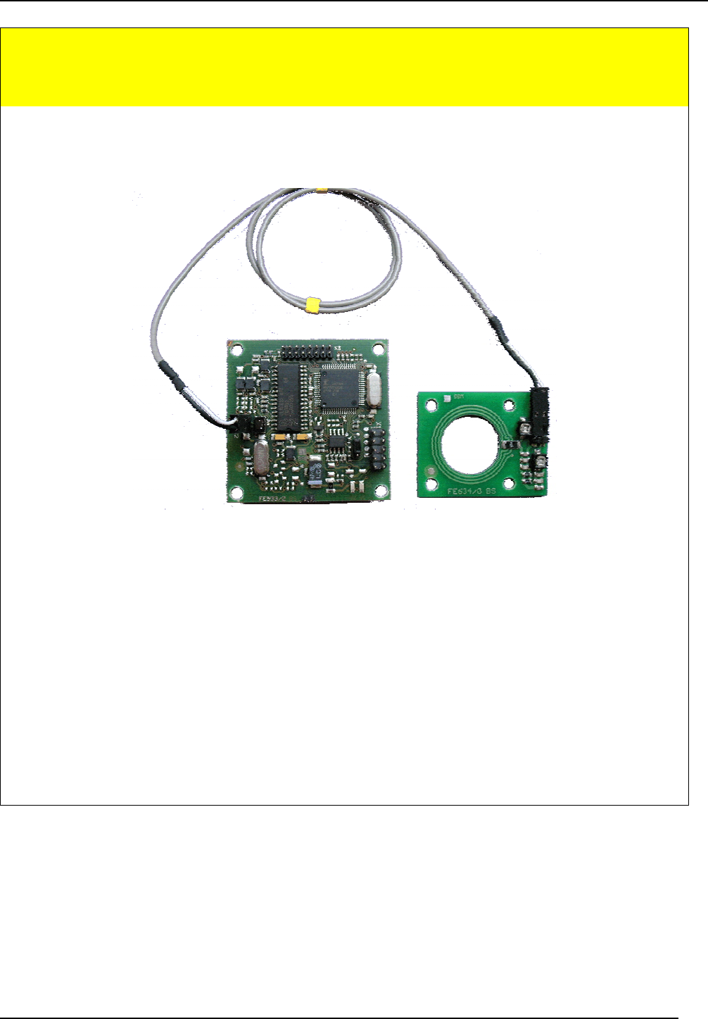
The ID CPR.M02 Reader Module is designed for reading and writing passive transponders having
an operating frequency of 13.56 MHz. It is suitable for any application in which short read ranges
and small reader dimensions are required.
2.2. Available module and antenna types
The following module types are currently available:
Modul Type Power Supply Antenna RS232-TTL
Interface
Data-/Clock
Interface
ID CPR.M02.VP/AB-C internal
ID CPR.M02.VP/AB-CA
5 V DC
external
4.800, 9.600,
19.200, 38.400,
57.600, 115.200,
230.400 Baud
Mag. Stripe
Wiegand
The following antenna types are currently available:
Antenna Description
ID ISC.ANT19 PCB- Antenna, 50Ω, Ø 19mm
2.3. Scope of delivery
The following components are included:
Modul Type Included
ID CPR.M02.VP/AB-C 1 x Reader Module ID CPR.M02.VP/AB-C
ID CPR.M02.VP/AB-CA 1 x Reader Module ID CPR.M02.VP/AB-CA
OBID® classic-pro Installation ID CPR.M02/ANT19
FEIG ELECTRONIC GmbH Page 7 of 20 Manual-M21001-3de-ID-B.doc
3. Installation and wiring
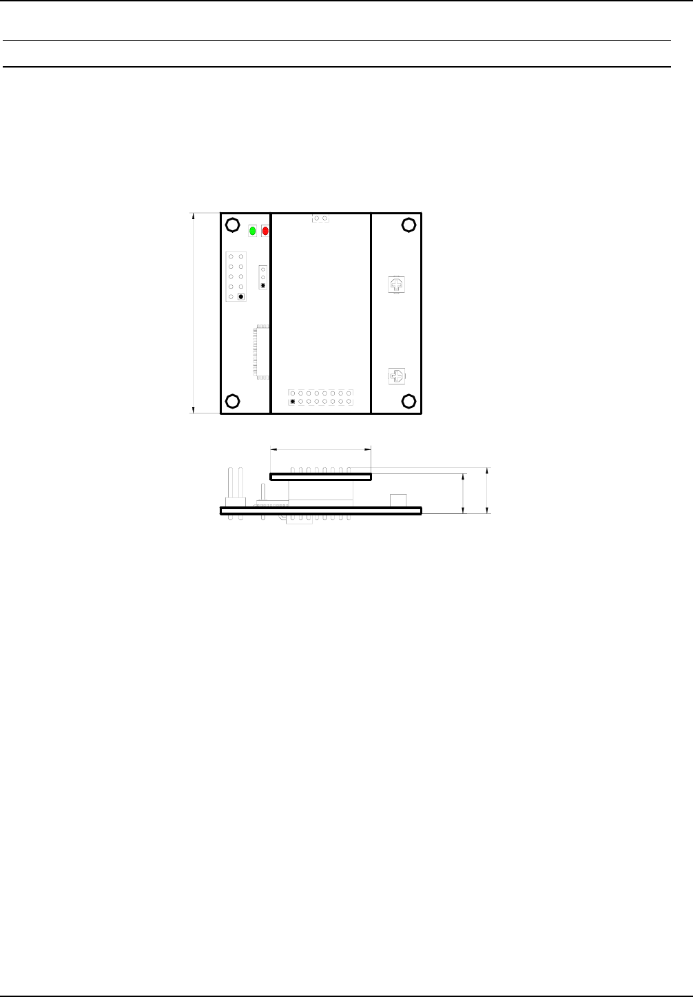
3.1. Dimensions
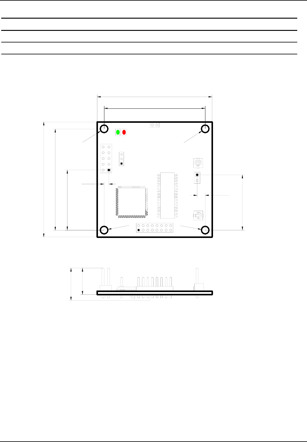
Fig. 3.1-1 shows the dimensions of the ID CPR.M02 Reader Module
Fig. 3.1-1: Dimensions of the ID CPR.M02 Reader Module
X1
J1
V2V1
C315
44,0
50,0
26,1
2,1
Ø3,3
Ø3,3
Ø3,3
Ø3,3
14,0
11,5
X3
X4
44,0
50,0
C405
X2
24,0
3,5
OBID® classic-pro Installation ID CPR.M02/ANT19
FEIG ELECTRONIC GmbH Page 8 of 20 Manual-M21001-3de-ID-B.doc
3.2. Wiring
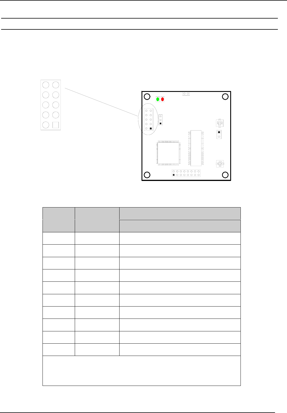
Fig. 3.2-1 and Table 3.2-1 show the pin assignments for Terminal X1. The pin connector is de-
signed for flat cable connection using an IDC multipoint socket connector with 2.54 mm pin spac-
ing.
Fig. 3.2-1: Pin assignments for Terminal X1
Description
X1
Pin no. Function ID CPR.M02
1DAT Data line for the data/clock interface
2CLK Clock line for the data/clock interface
3TxD RS232-TTL – Transmit Data
4GND ** GND
5RxD RS232-TTL – Receive Data
6--- not connected
7CLS CLS line for the data/clock interface
8VCC + 5 V DC *
9GND ** GND
10 --- not connected
* Use only regulated DC power supplies !
** GND-Pins 4 and 9 are to be connected directly to each other
on the Reader Module
Table 3.2-1: Pin assignments for Terminal X1
X1
J1
V2V1
C315
X1
12
43
5
7
9
6
8
10
X3
X4
C405
X2

OBID® classic-pro Installation ID CPR.M02/ANT19
FEIG ELECTRONIC GmbH Page 9 of 20 Manual-M21001-3de-ID-B.doc
3.2.1. Supply voltage
The ID CPR.M02 must be supplied only by a regulated power supply. If switching power supplies
are used with the module, be sure that there is adequate filtering. Noise from the power supply can
result in a reduction of the read/write range of the module. The cable length from the power supply
should be as short as possible, and should in any case not exceed 3 m.
Description
X1
Pin no. Function ID CPR.M02
8VCC * + 5 V DC ± 5%
9, 4 GND ** GND
* Use only regulated power supplies !
** GND-Pins 4 and 9 are to be connected directly to each
other on the Reader Module
Table 3.2.1-1: Pin assignments for X1
NOTE:
• Reversing the polarity of the supply voltage may destroy the device.
• Supply voltages outside the specifications may destroy the device.

OBID® classic-pro Installation ID CPR.M02/ANT19
FEIG ELECTRONIC GmbH Page 10 of 20 Manual-M21001-3de-ID-B.doc
3.2.2. RS232 interface
The length of the cable to the RS232 interface should be kept as short as possible, and must in
any case not exceed 3 m.
Description
X1
Pin no. Function ID CPR.M02
3TxD * RS232-TTL - Transmit Data
4, 9 GND ** GND
5RxD * RS232-TTL - Receive Data
* Signal names as seen by the Reader Module.
** GND-Pins 4 and 9 are to be connected directly to each
other on the Reader Module
Table 3.2.2-1: Pin assignments for the RS232 interface on X1
The transmission parameters for the interface can be software-configured. Table 3.2.2-2 shows the
standard parameters for the RS232 interface.
Parameter Standard setting
Baud rate 38400
No. of data bits 8
Parity Even
No. of stop bits 1
Table 3.2.2-2: Standard parameters of the RS232 interface.
OBID® classic-pro Installation ID CPR.M02/ANT19
FEIG ELECTRONIC GmbH Page 11 of 20 Manual-M21001-3de-ID-B.doc
3.2.3. Data/Clock interface
The length of the cable to the data/clock interface should be kept as short as possible. It must not
exceed 3 m.
Description
X1
Pin no. Function ID CPR.M02
1DAT Data line for the data/clock in-
terface
2CLK Clock line for the data/clock
interface
7CLS CLS line for the data/clock in-
terface
4, 9 GND * GND
* GND-Pins 4 and 9 are to be connected directly to each
other on the Reader Module
Table 3.2.3-1: Pin configuration for the RS232 interface on Terminal X1
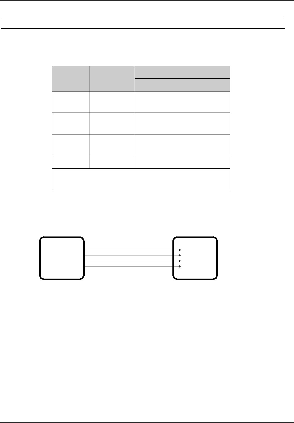
Fig. 3.2.3-1: Connecting the data/clock interface
Host ID CPR.M02
DAT
CLK
CLS
GND
Data
GND
Clock
CLS
OBID® classic-pro Installation ID CPR.M02/ANT19
FEIG ELECTRONIC GmbH Page 12 of 20 Manual-M21001-3de-ID-B.doc
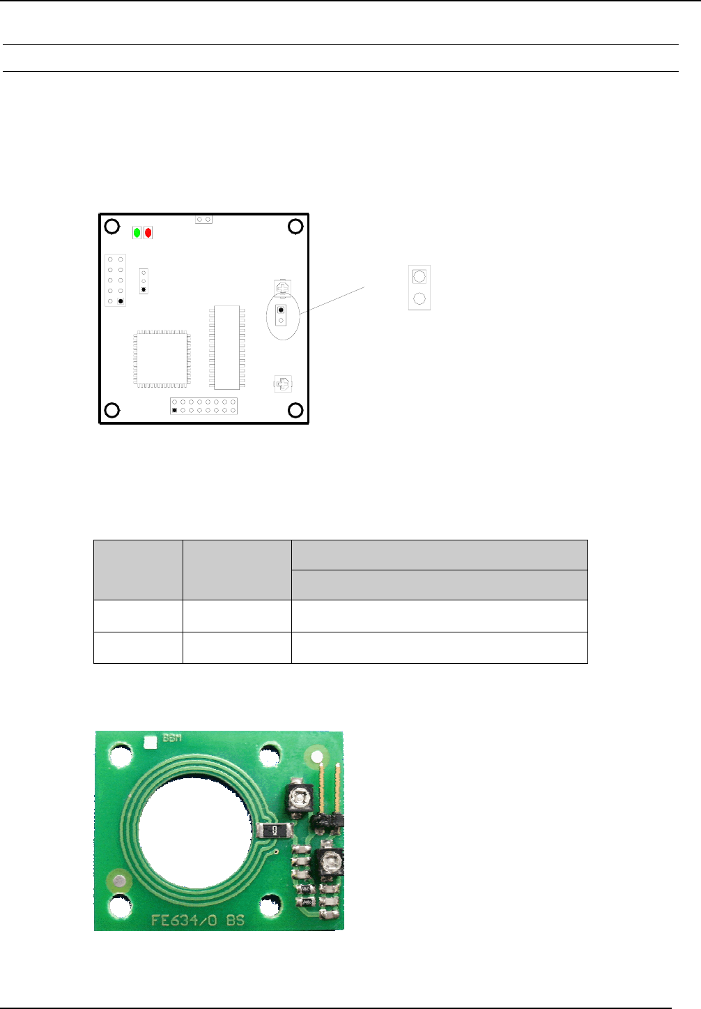
3.2.4. Connection of an external Antenna (ID ISC.ANT19)
The ID CPR.M02.VP/AB-CA are intended for the connection of an external 50Ω-Antenna.
The use of the integrated antenna is not possible with this version.
Fig. 3.2.4-1 and Table 3.2.4-1 shows the pin assignments for Terminal X2 for the connection of the
external antenna. The pin connector has a pin spacing of 2.54mm.
Fig. 3.2.4-1: Pin assignment of Terminal X2
Description
X2
Pin no. Function ID CPR.M02.VP/AB--CA
1Signal Signal pin of the external 50Ω-Antenna
2GND GND pin of the external 50Ω-Antenna
Table 3.2.4-1: Pin assignment of Terminal X2
Fig. 3.2.4-2: Ext. 50Ω antenna ID ISC.ANT19
X1
J1
V2
V1
C315
X3
X4
X2 Connector
ext. Antenna
GND
Signal }
1
2
C405
X2
OBID® classic-pro Installation ID CPR.M02/ANT19
FEIG ELECTRONIC GmbH Page 13 of 20 Manual-M21001-3de-ID-B.doc
3.2.5. Optional Module ID SAM.M02
If needed, the optional device ID SAM.M02 can be connected to terminals X3 and X4. The
ID SAM.M02 is a module for connecting and driving an additional SAM and provides security by
using cryptographic data transmission between the reader and transponder.
Fig. 3.2.4-1: Dimensions of ID CPR.M02 with ID SAM.M02
V2V1
50,0
X1
X3
X4
25,0
10,0
11,5
C315
OBID® classic-pro Installation ID CPR.M02/ANT19
FEIG ELECTRONIC GmbH Page 14 of 20 Manual-M21001-3de-ID-B.doc
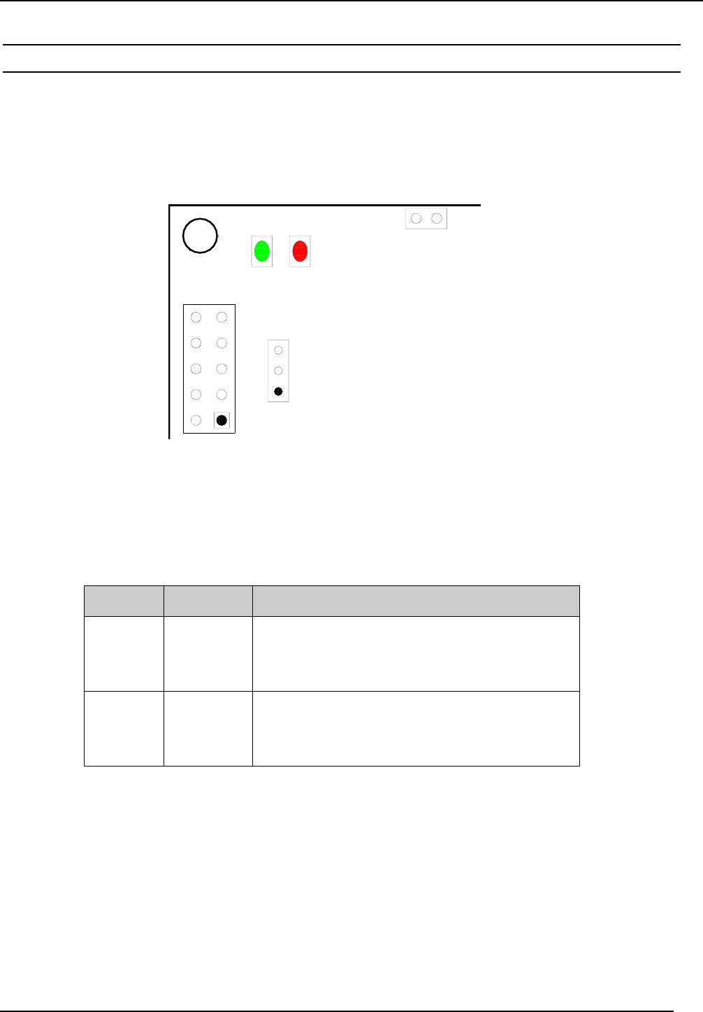
3.3. Display elements
The ID CPR.M02 Reader Module has a green LED (V1) and a red LED (V2) which are used as
display elements (Fig. 3.3-1).
Fig. 3.3-1: Position of LEDs V1 and V2
LED Color Standard setting
V1 Green
• Flashes 4x after a reset.
• Flashes continuously at a frequency of
2 Hz.
V2 Red
• Flashes 4x after a reset.
• Comes on for 1 second after successful
communication with a transponder.
Table 3.3-1: Standard setting for the LEDs
NOTE:
Up from Firmware-Version 1.08 the function of the red LED is connected to X1, Pin7 (CLS).
For current limitation an additional resistor with 470
Ω
is required.
X1
J1
V2V1 X4
OBID® classic-pro Installation ID CPR.M02/ANT19
FEIG ELECTRONIC GmbH Page 15 of 20 Manual-M21001-3de-ID-B.doc
3.4. Operating elements
3.4.1. Operating/Programming Mode: Jumper J1
Jumper J1 is used to configure the operating and programming mode of the ID CPR.M02.
In standard operation the jumper is set to Position 1-2 (see Fig. 4.3.1-1). The reader is then in
normal operating mode.
If the jumper is set to Position 2-3, the integrated hardware bootloader starts after a reset. Since
the reader’s firmware however also has a software bootloader, the hardware bootloader option
should be used only if necessary.
For additional information about programming the reader, see the corresponding Application Note
„Firmware Update“.
Jumper position Mode
1 - 2 Standard setting :
The reader is in normal operating mode.
2 - 3
Activation of the hardware bootloader:
After a reset the reader’s CPU starts its hardware
bootloader, which can then be used for new pro-
gramming.
Table 3.4.1-1: Jumper J1
Fig. 3.4.1-1: Jumper J1
X1
J1
V2V1
C315
X3
X4 Default
2
1
J1
3
C405
OBID® classic-pro Installation ID CPR.M02/ANT19
FEIG ELECTRONIC GmbH Page 16 of 20 Manual-M21001-3de-ID-B.doc
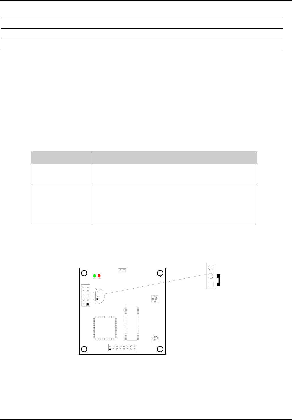
3.4.2. Retuning the internal antenna (ID CPR.M02.VP/AB-C)
The antenna of the ID CPR.M02.VP/AB-C can be detuned as a result of various ambient condi-
tions such as nearby metal objects (see Section 8.5). This detuning can be compensated to some
degree using the trim capacitor C315.
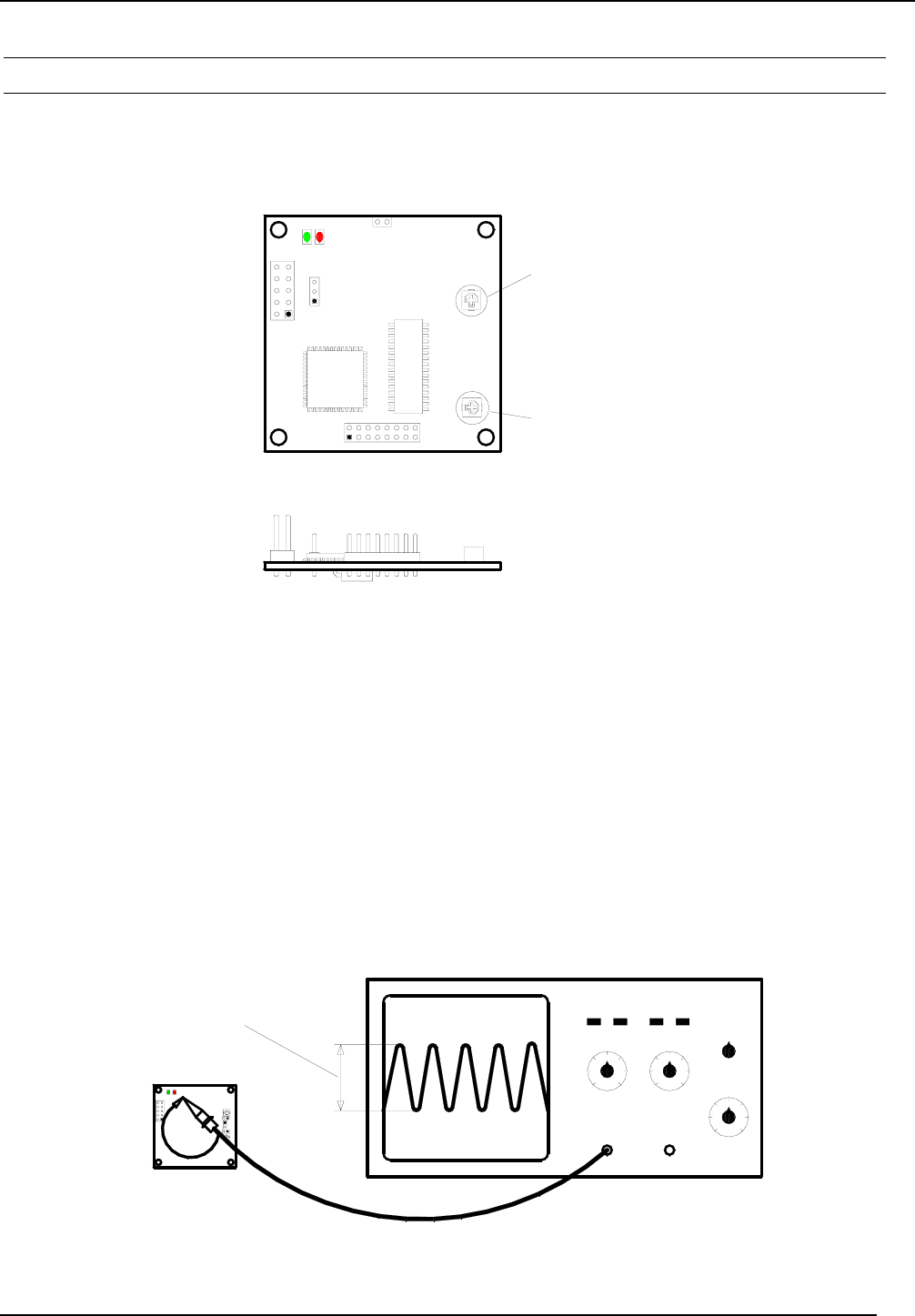
Fig. 3.4.3-1: Trim capacitor for retuning the antenna
The integrated antenna can be retuned with the aid of an oscilloscope (bandwidth ≥ 20 MHz). To
do this, short the GND terminal of the oscilloscope probe with the probe point and hold it over the
circuit board of the ID CPR.M02. The probe then forms a measuring loop for the radiated magnetic
field of the ID CPR.M02. The distance between the oscilloscope probe and the ID CPR.M02 should
be between 0 and 3 cm.
Use the software command „RF-ON“ (0x6A) to turn on the HF field of the ID CPR.M02. A 13.56
MHz signal should be visible on the oscilloscope screen.
To tune the internal antenna, now set the signal amplitude of the 13.56 MHz signal to maximum
using trim capacitor C315.
Fig. 3.4.3-2: Configuration for tuning the internal antenna
X1
J1
V2V1
C315
X3
X4
C405
Trim capacitor C315:
Retuning the integrated
antenna
Trim capacitor C405:
DO NOT CHANGE !!!
ID CPR.M02
V1 V2
X1
C65
Turn C315 to set amplitude
to maximum

OBID® classic-pro Installation ID CPR.M02/ANT19
FEIG ELECTRONIC GmbH Page 17 of 20 Manual-M21001-3de-ID-B.doc
Use caution when the maximum value of the signal amplitude is reached at the minimum or maxi-
mum position of the trim capacitor (Fig. 3.4.3-3). This usually means the antenna is too severely
detuned by the surroundings and can no longer be fully compensated by the trim capacitor.
Beschriftung
Minimale
Kapazität Maximale
Kapazität
Fig. 3.4.3-3: Minimum and maximum position of the trim capacitor C315
After the antenna has bee tuned, check it again for maximum range and any communication gaps.
NOTE:
• Notwithstanding the possibility of retuning the antenna as described here, the distance
between the reader and the surrounding metal surfaces must be at least 3 cm. Note that
even other circuit boards may act like metal objects depending on how much copper
they contain.
Labeling
Minimum
capacitance
Maximum
capacitance

OBID® classic-pro Installation ID CPR.M02/ANT19
FEIG ELECTRONIC GmbH Page 18 of 20 Manual-M21001-3de-ID-B.doc
3.5. Installation notes
Be aware of the following possible environmental factors when installing an ID CPR.M02 into an-
other device :
• Effects from nearby metal objects
⇒ Detuning of the integrated antenna
⇒ Impaired propagation of the antenna’s magnetic field
• EMC effects on cables
⇒ Impaired communication between reader and transponder
• EMC effects from magnetic fields
⇒ Impaired communication between reader and transponder
3.5.1. Metallic surroundings
When installing an ID CPR.M02 into another device, be sure that there are no metal surfaces or
objects in the direct vicinity of the reader if possible. These can detune the antenna and thus re-
duce the magnetic field of the integrated antenna. This will in turn result in reduced read distances
for the reader.
The distance between the reader and a metal surface should be at least 3 cm. Note that
even other circuit boards may act line metal objects depending on how much copper they
contain.
If a metallic surrounding cannot be avoided, stable function should at least be ensured by keeping
the distance as great as possible.
The area between the antenna and transponder as well as the area on the other side of the trans-
ponder should also be kept clear of metal parts.
Since any change in the metallic environment will result in detuning of the integrated antenna and
therefore to impaired function, no moving metal parts, such as metallic fans, should be allowed in
the vicinity of the reader.
3.5.2. EMC effects on cables
In spite of the internal EMC filters inside the reader, high levels of noise on the supply voltage can
result in impairment of the communication between the reader and transponder.
When installing an ID CPR.M02 into another device, be sure therefore that a clean, noise-free
power supply is used.

OBID® classic-pro Installation ID CPR.M02/ANT19
FEIG ELECTRONIC GmbH Page 19 of 20 Manual-M21001-3de-ID-B.doc
3.5.3. EMC effects from magnetic fields
Since in this type of RFID-Technology the communication between the reader and transponder
takes place by modulation of a magnetic field, alternating magnetic fields in the vicinity of the an-
tenna can have a negative impact on its function.
Sources of such magnetic interference fields include coils within a primary or secondary switching
power supply.
When determining the position of the reader and antenna within a device, check the device for any
possible sources of interference as described above. If necessary, use shielding to suppress such
interference.

OBID® classic-pro Installation ID CPR.M02/ANT19
FEIG ELECTRONIC GmbH Page 20 of 20 Manual-M21001-3de-ID-B.doc
4. Radio Approvals
4.1. Europe (CE)
When used according to regulation, this radio equipment conforms with the basic requirements of
Article 3 and the other relevant provisions of the R&TTE Guideline 1999/E6 dated March 99.
Equipment Classification according ETSI EN 300 330: Class 2
4.2. USA (FCC)
FCC ID PJMCPRM02-ANT19
This device complies with Part 15 of the FCC Rules. Operation is subject to the following
two conditions:
(1) this device may not cause harmful interference, and
(2) this device must accept any interference received, including interference that may
cause undesired operation.
Any changes or modifications not expressly approved by the party responsible for com-
pliance could void the user's authority to operate the equipment.
This device is labeled with an FCC ID number.
If this label is not visible when installed in an end device, the outside of the device MUST
also display a label referring to the enclosed module.
Wording on the label similar to the following shall be used:
This device contains transmitter module FCC ID PJMCPRM02-ANT19
At the time of this printing, the antennas listed below were the only antennas approved for
use with the ID CPR.M02 module. Use of other antennas must be approved by
FEIG ELECTRONIC GmbH.
Antennas approved: ID ISC.ANT19
The FCC sticker is glued at the package.
ID CPR.M02/ANT19
FEIG
ELECTRONIC
FCC ID PJMCPRM02-ANT19

OBID® classic-pro Installation ID CPR.M02/ANT19
FEIG ELECTRONIC GmbH Page 21 of 20 Manual-M21001-3de-ID-B.doc
5. Technical Data
• Dimensions ( W x H x D ) 50 mm x 50 mm x 14 mm
• Connector 10 pol. Pin-Connector (grid dim. 2,54 mm)
• Supply voltage 5 V DC ± 5% ripple
0...250 kHz < 10 mVpp
ab 250 kHz < 0,1 mVpp
• Power Consumption max. 1,5 W
• Operating Frequency 13.56 MHz
• RF Transmitting Power 250 mW ± 2 dB
• Antenna: ID CPR.M02.VP/AB-CA External (separate 2 pol. Pin-Connector)
• RS232-TTL Interface:
ID CPR.M02.VP/AB-C / -CA 4.800 to 230.400 Baud
• Daten-/Takt Interface • Magnet Stripe Emulation
• Wiegand Emulation
• EEPROM (for parameters) 1 kB (10,000 write cycles)
• FLASH 64 kB (software update on interface possible)
• Supported Transponders
read and write
• ISO14443-A compatible
(e. g. mifare, mifare Ultra Light, my-d proximity)
• ISO14443-B compatible
• ISO15693 compatible
(e. g. I•Code SLI, Tag-It HFI, my-d vicinity, STM
LRI512)
• I•Code 1 (optional)
• Security Function (optional) SAM (Security Access Module),
e.g. for my-d vicinity and my-d proximity
• Optical Indicators LED green: running;
LED red: Transponder detected
• Temperature Range Operating
Storage
-20°C to +70°C
-40°C to +85°C
• Radio Approval Europe
USA
EN 300 330
FCC 47 CFR Part 15
• EMC EN 301 489
• Safety EN 60950