Feig Electronic LRM1002 RFID Reader User Manual
Feig Electronic GmbH RFID Reader
UserManual.wiki
>
Feig Electronic
>
LRM1002 User Manual
>
user manual
Contents
1.
user manual
2.
User manual
3.
Users Manual
user manual
Navigation menu
Upload a User Manual
Namespaces
Wiki Guide
HTML
PDF
Info
Views
User Manual
Discussion / Help
Navigation
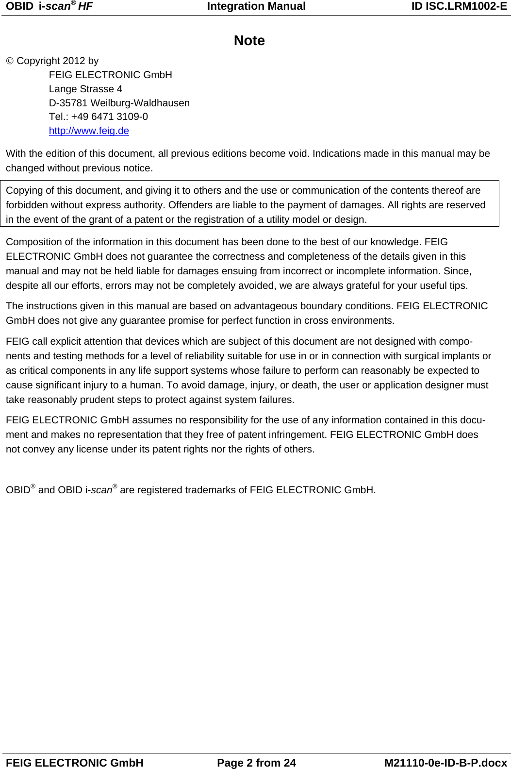
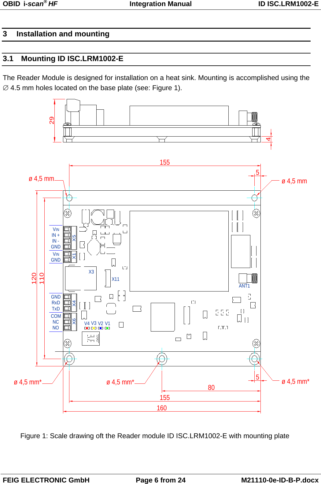
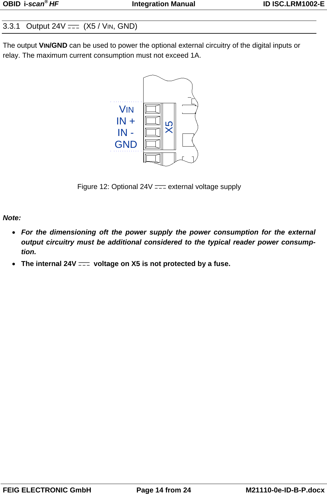
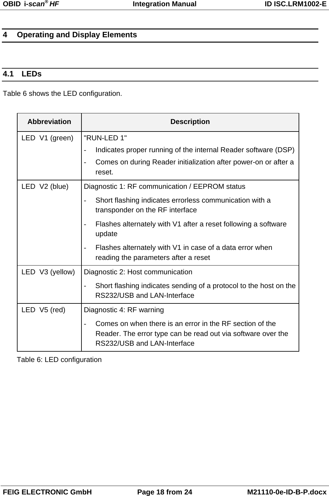
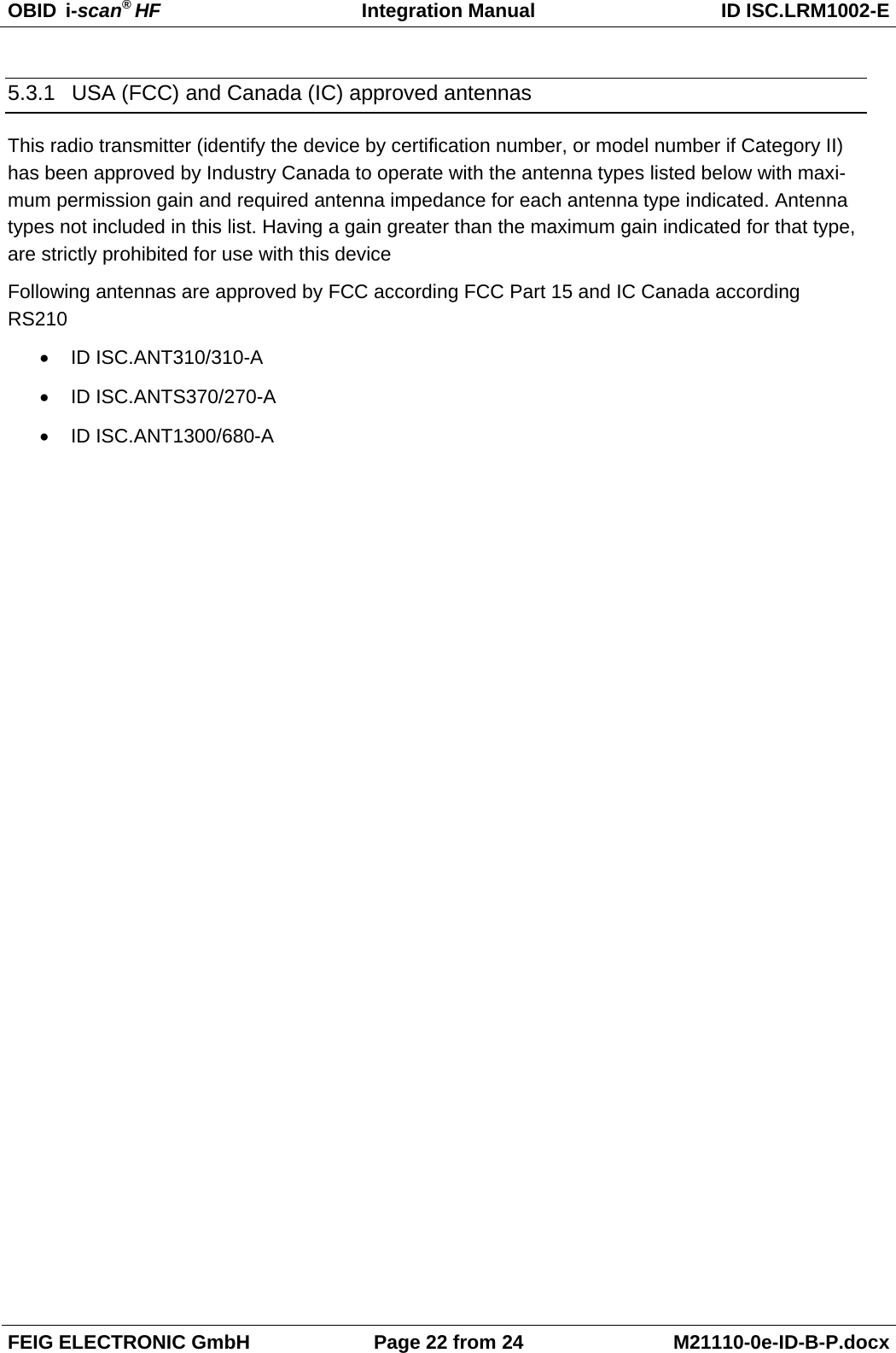

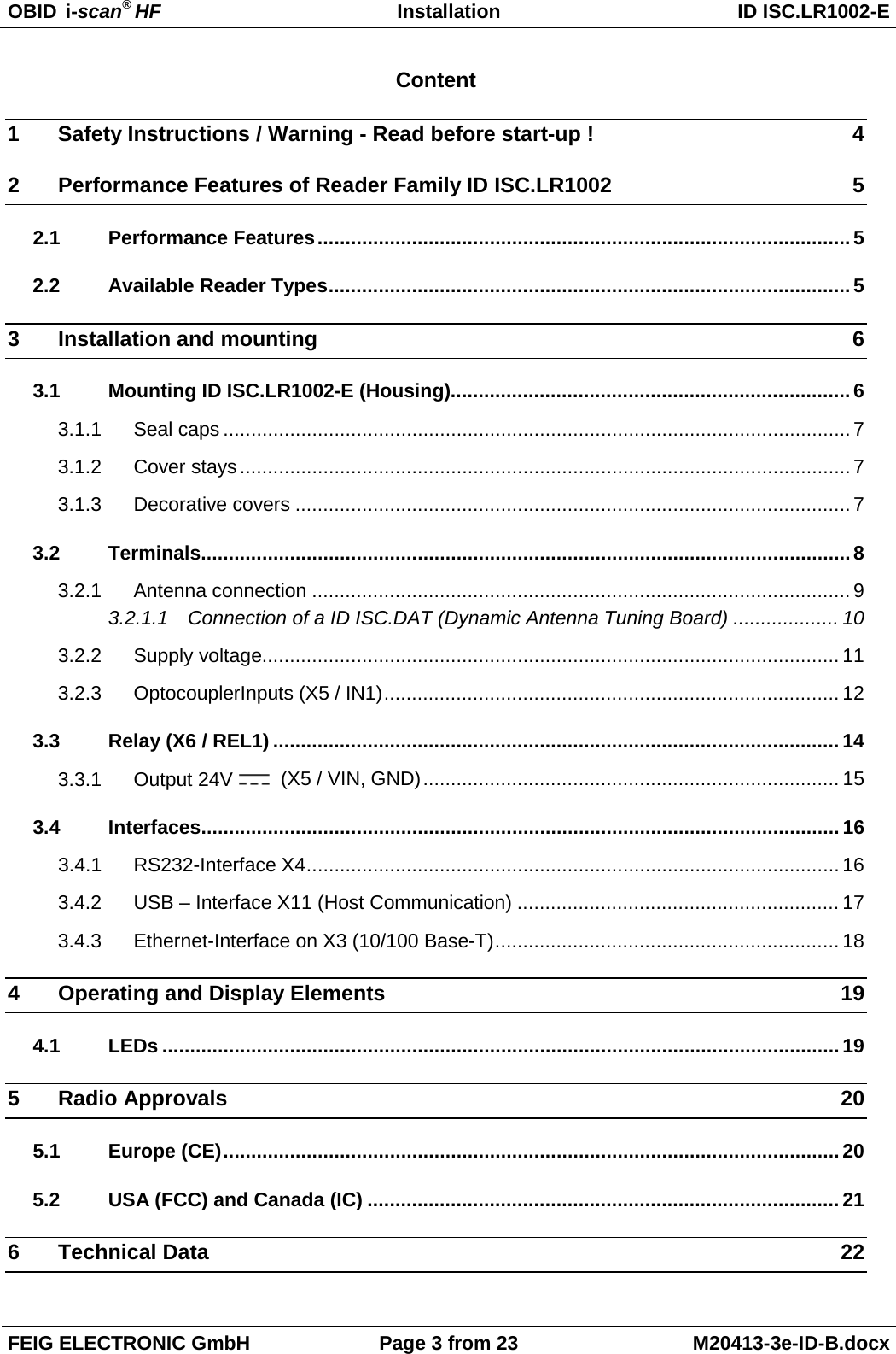
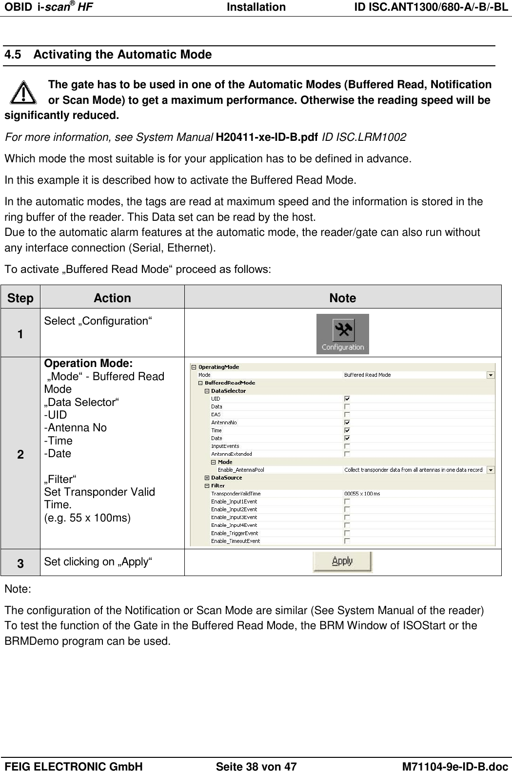
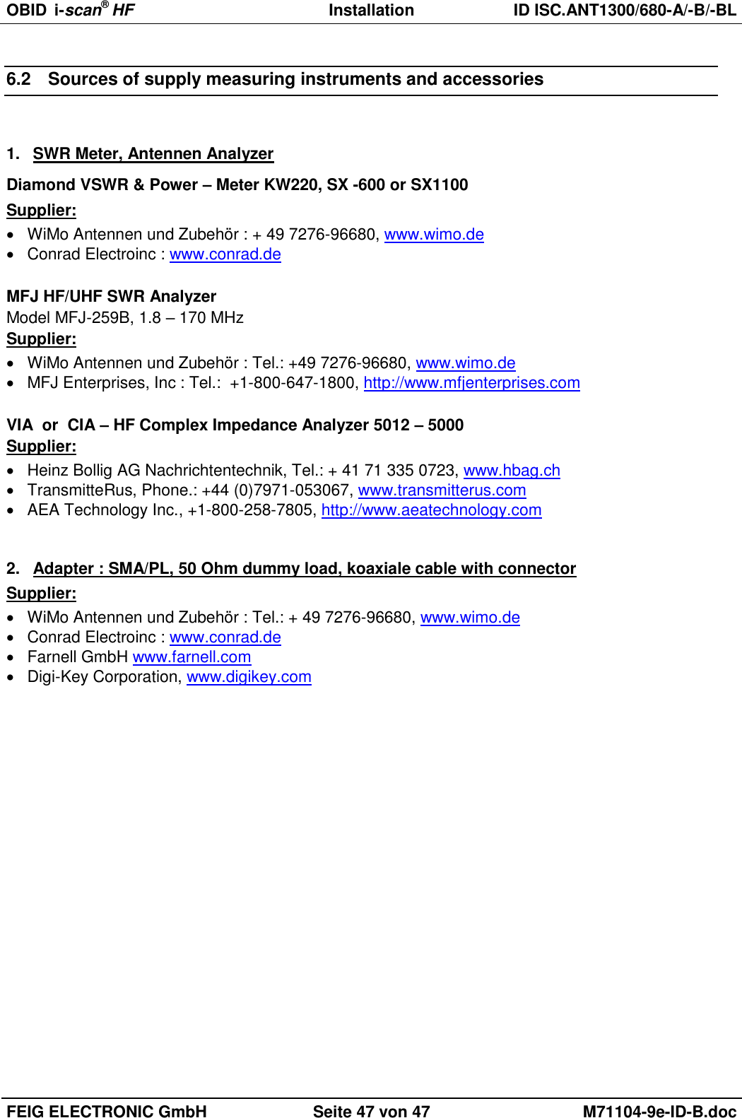
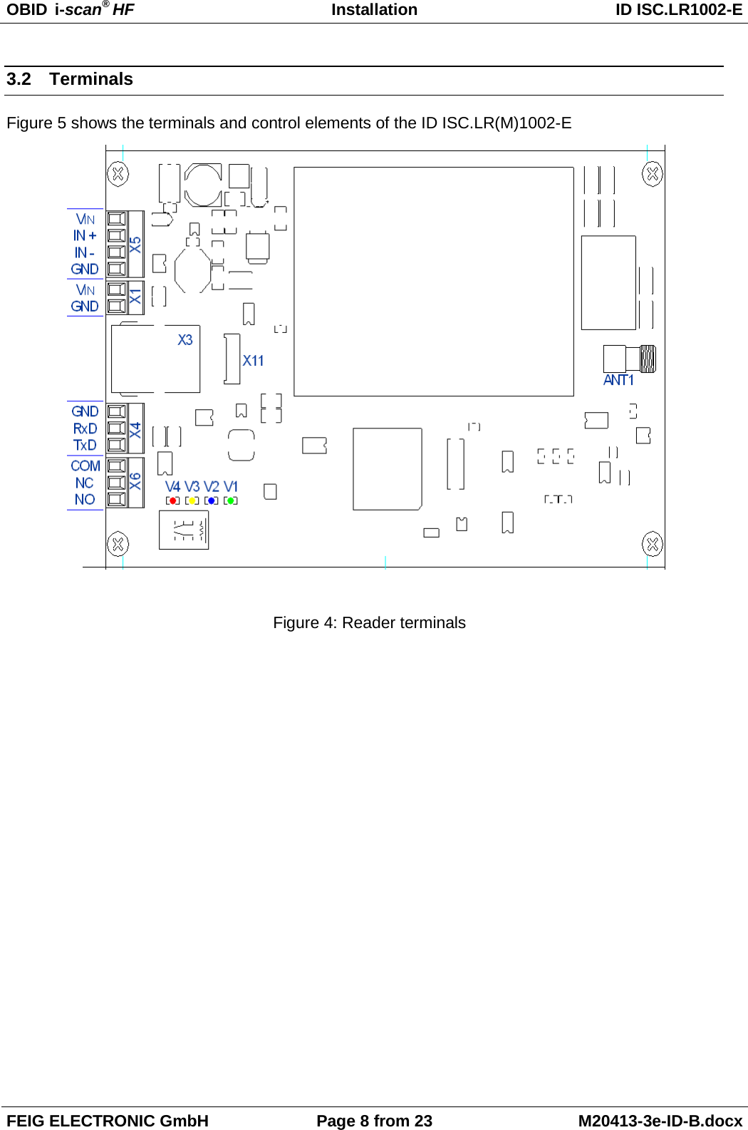
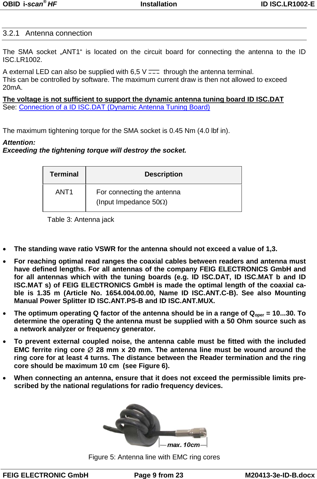
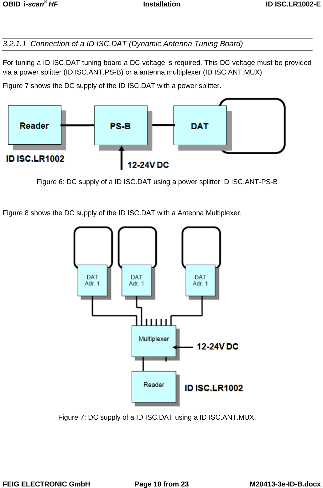
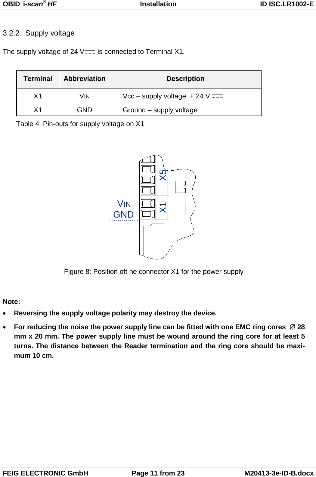
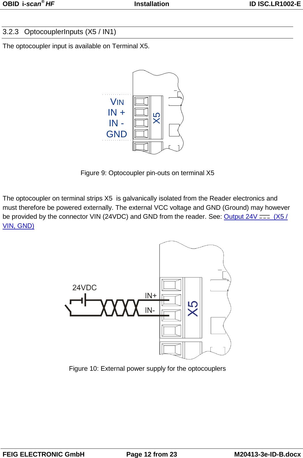
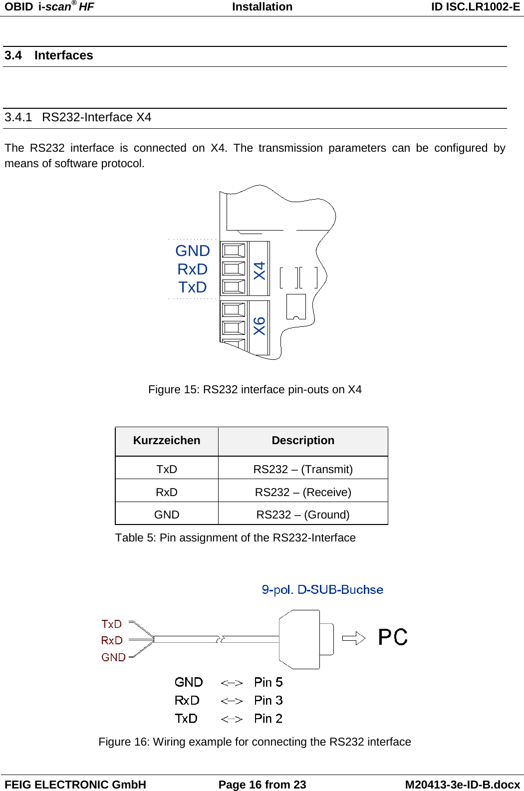
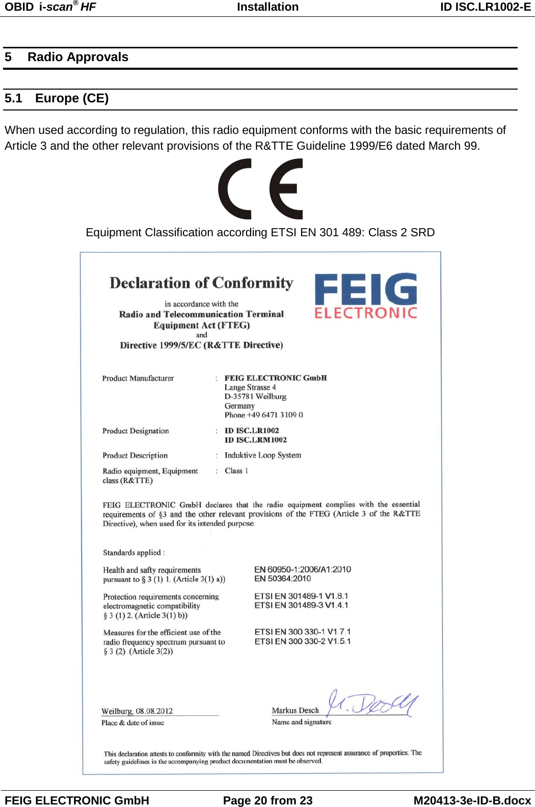
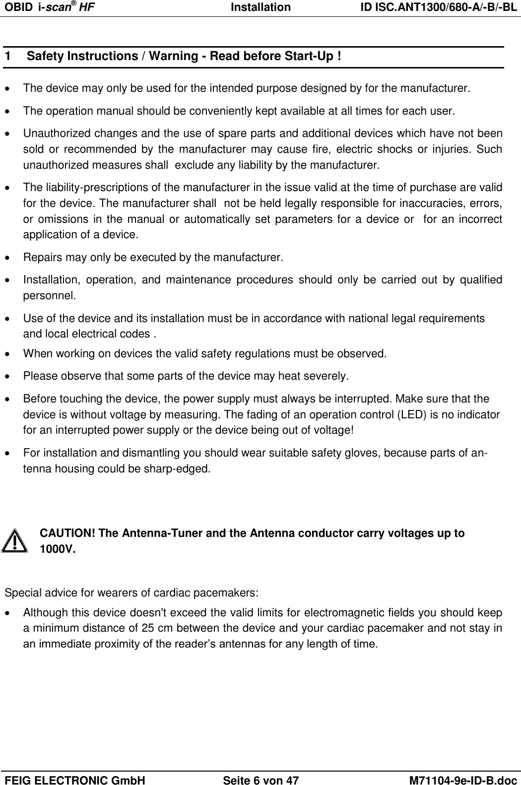
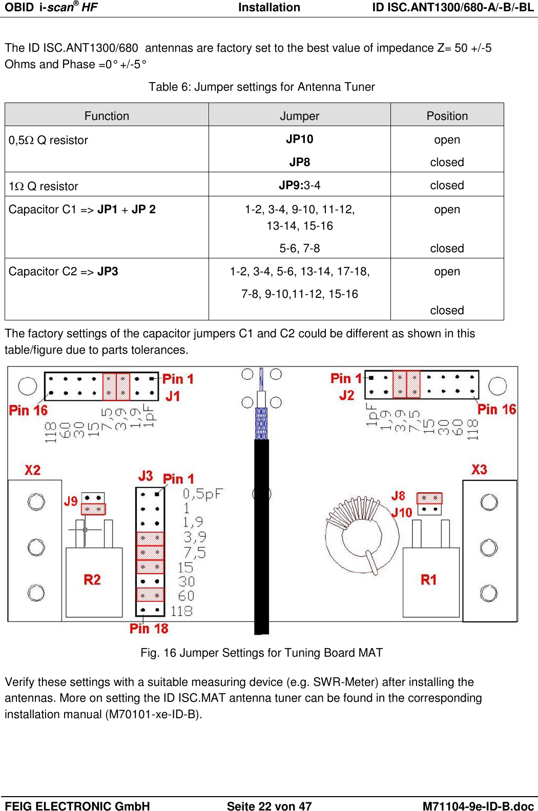
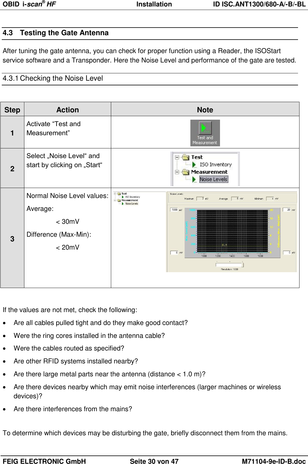
![OBID i-scan® HF Installation ID ISC.LR1002-E FEIG ELECTRONIC GmbH Page 6 from 23 M20413-3e-ID-B.docx 3 Installation and mounting 3.1 Mounting ID ISC.LR1002-E (Housing) The Reader is designed for wall mount, including outdoors. Holes are provided in the housing for wall attachment. The housing does not need to be opened for installation on a wall (see Figure 2). USB / LANHFInput / OutputRunHostDiag.AntennaCom Power Figure 1: Housing ID ISC.LR1002-E (all dimensions in mm) Cable gland Size Clamping range [mm] Description 1 M 16 4,5 – 10 Antenna cable 2 M 12 3,5 – 7 Supply voltage 3 M 12 3,5 – 7 Interface (serial/USB) 2 M 16 4,5 – 10 Digital Input / Relais Output 6 M 25 9 – 17 Ethernet Interface Table 2: Cable glands ID ISC.LR1002-E](https://usermanual.wiki/Feig-Electronic/LRM1002.user-manual/User-Guide-1851272-Page-31.png)
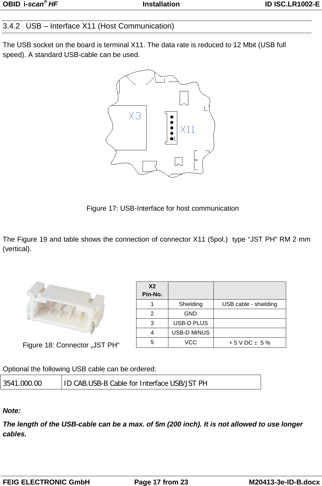
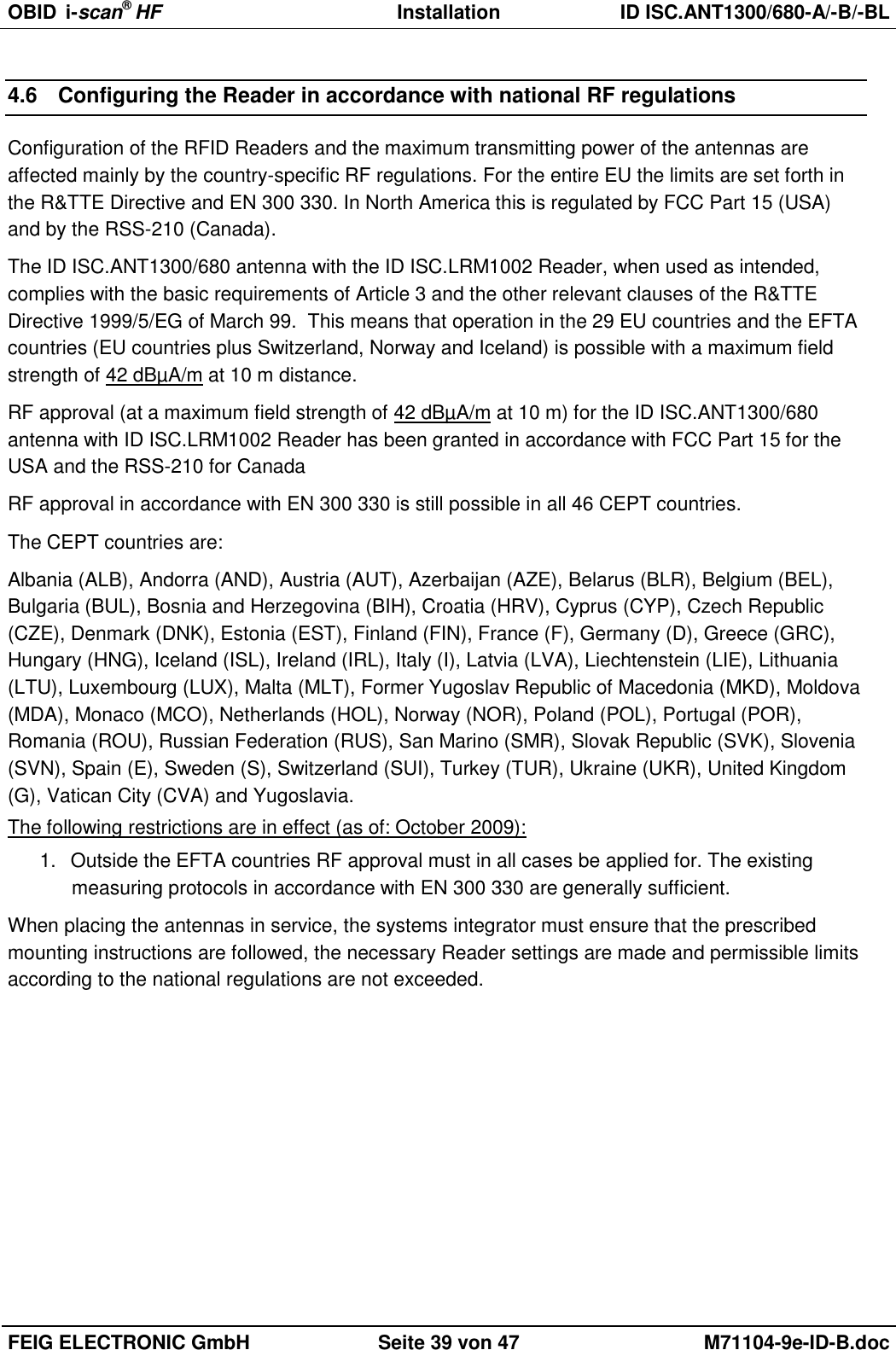
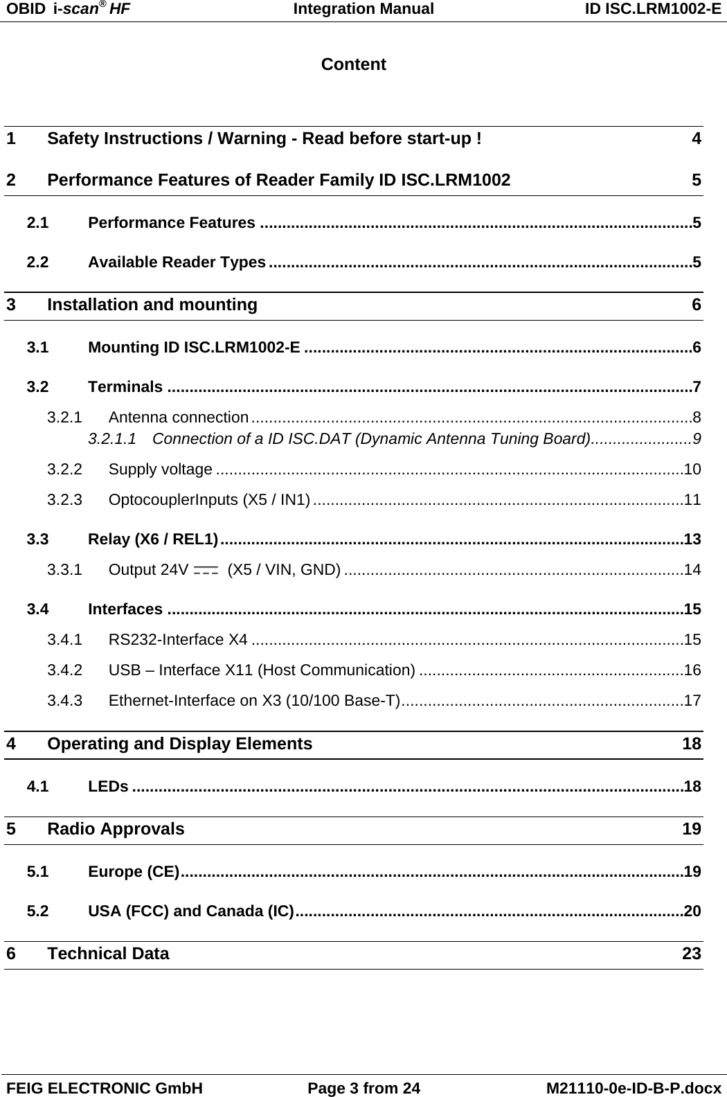
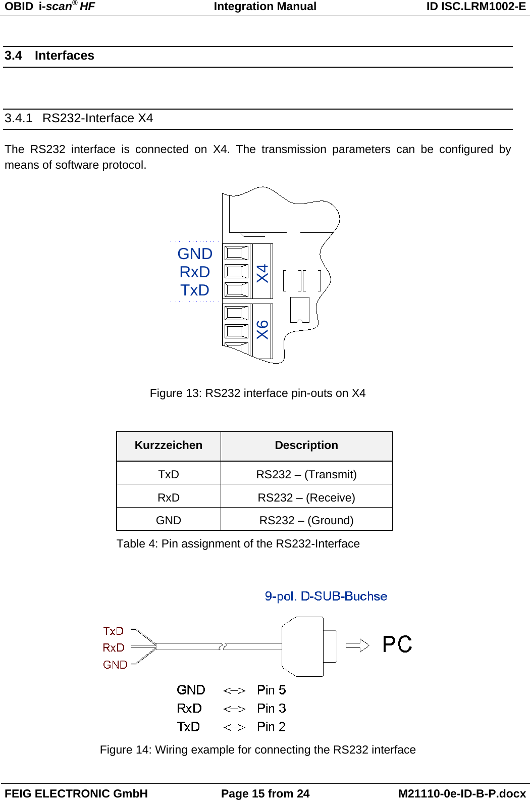
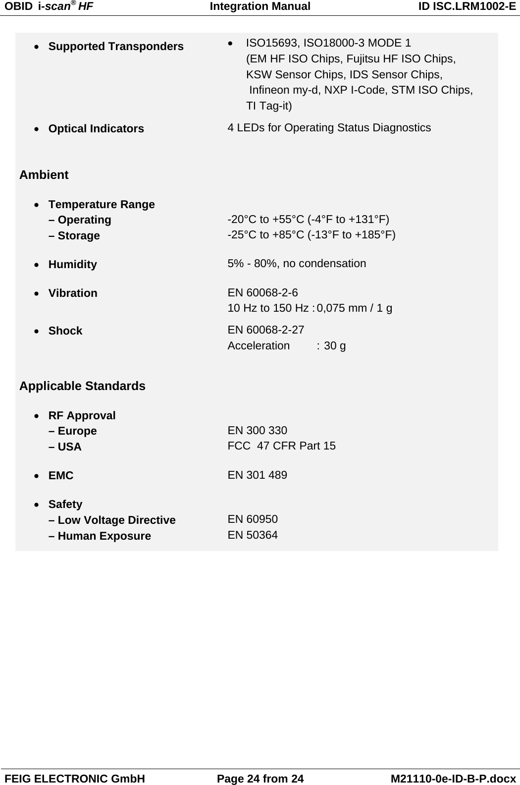
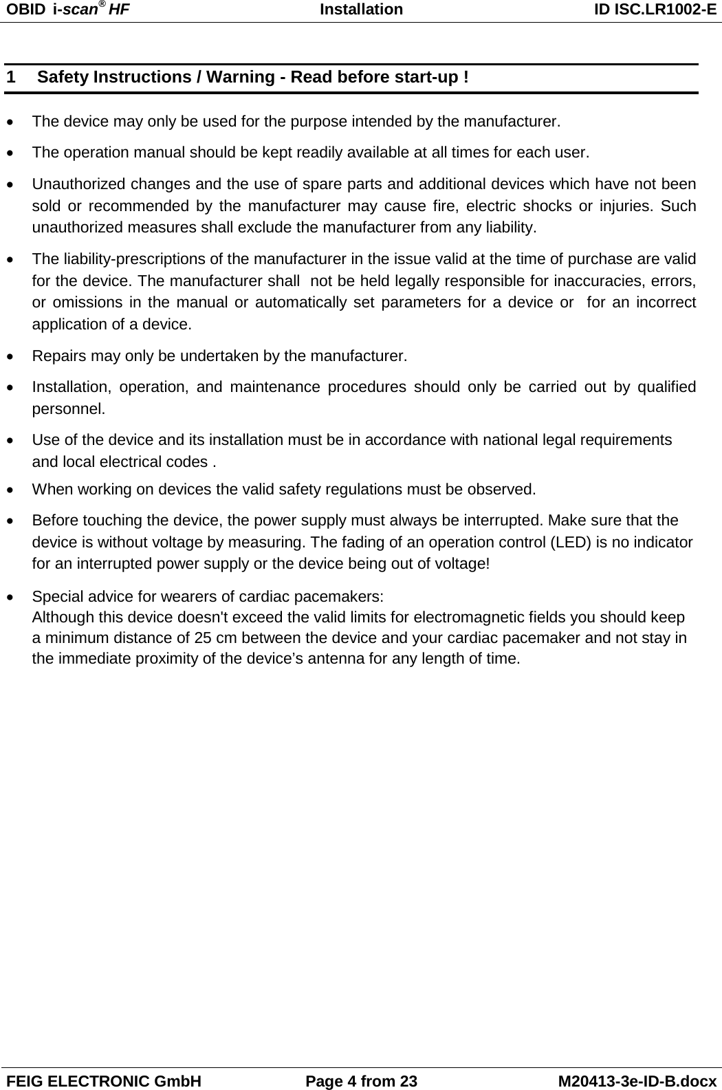
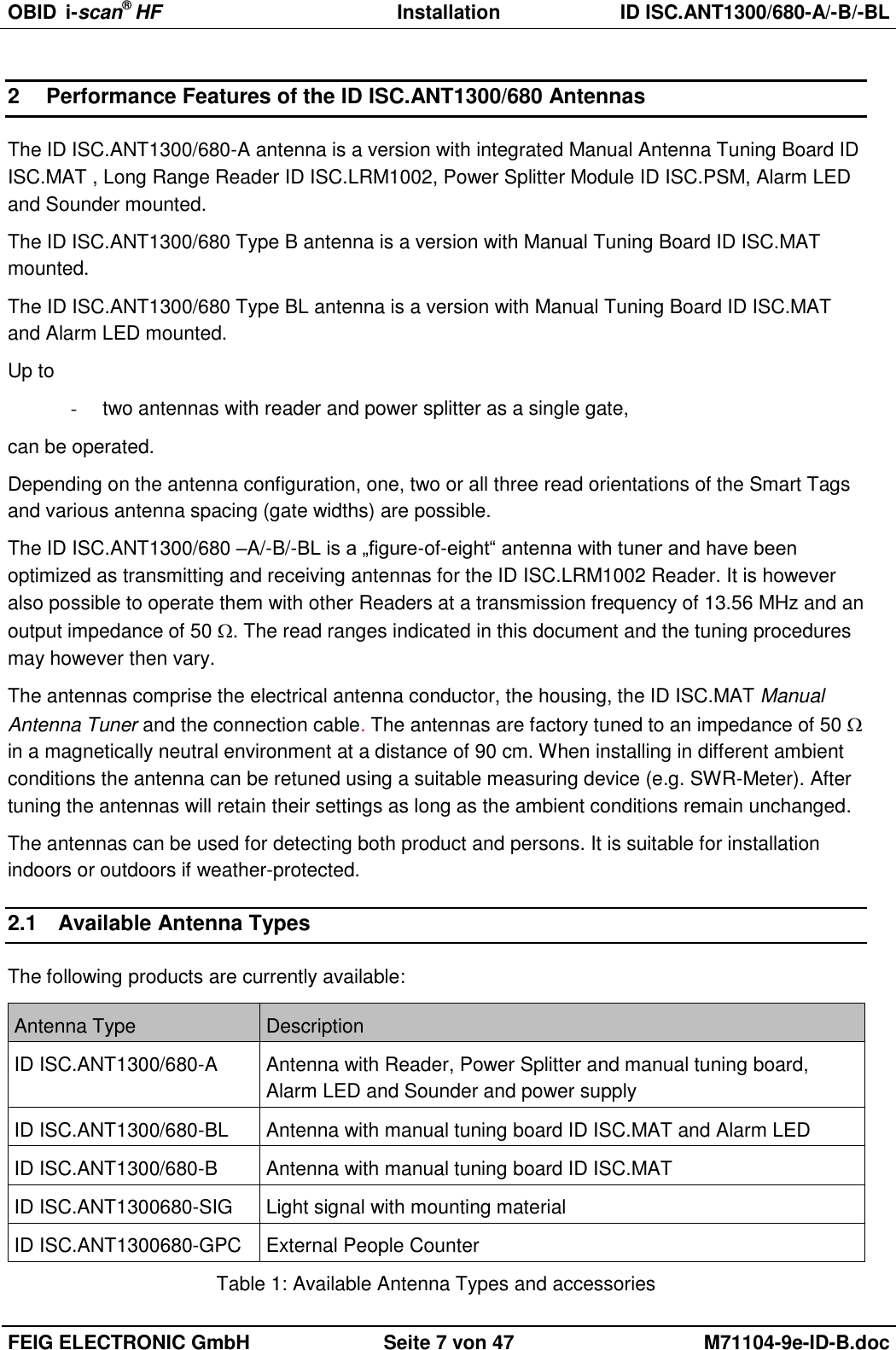
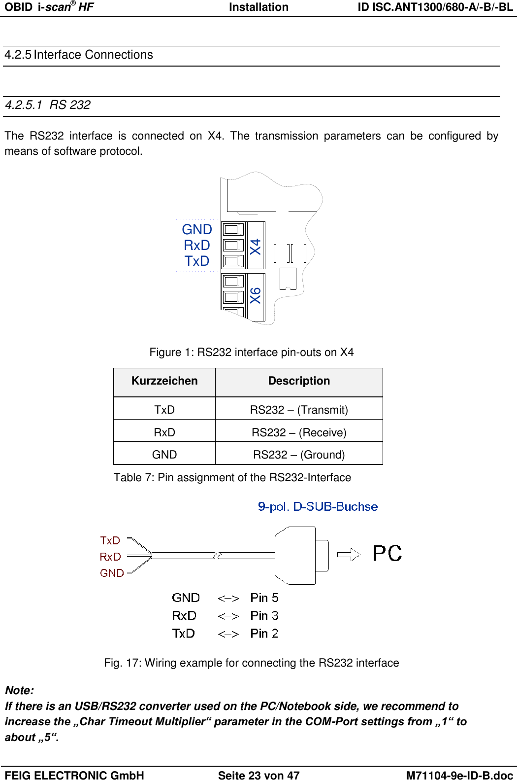
![OBID i-scan® HF Installation ID ISC.ANT1300/680-A/-B/-BL FEIG ELECTRONIC GmbH Seite 3 von 47 M71104-9e-ID-B.doc General information's regarding this document The sign "" indicates extensions or changes of this manual compared with the former issue. If bits within one byte are filled with "-", these bit spaces are reserved for future extensions or for internal testing- and manufacturing-functions. These bit spaces must not be changed, as this may cause faulty operation of the reader. The following figure formats are used: 0...9: for decimal figures 0x00...0xFF: for hexadecimal figures, b0...1 for binary figures. The hexadecimal value in brackets "[ ]" marks a control byte (command).](https://usermanual.wiki/Feig-Electronic/LRM1002.user-manual/User-Guide-1851272-Page-51.png)
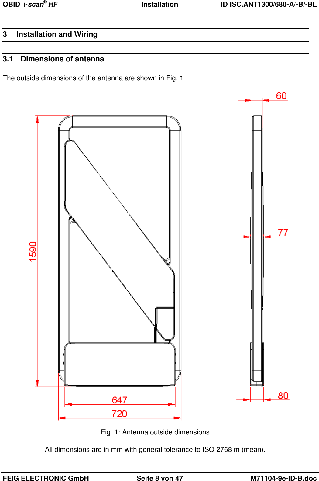
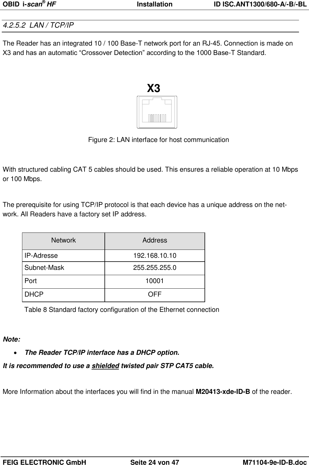
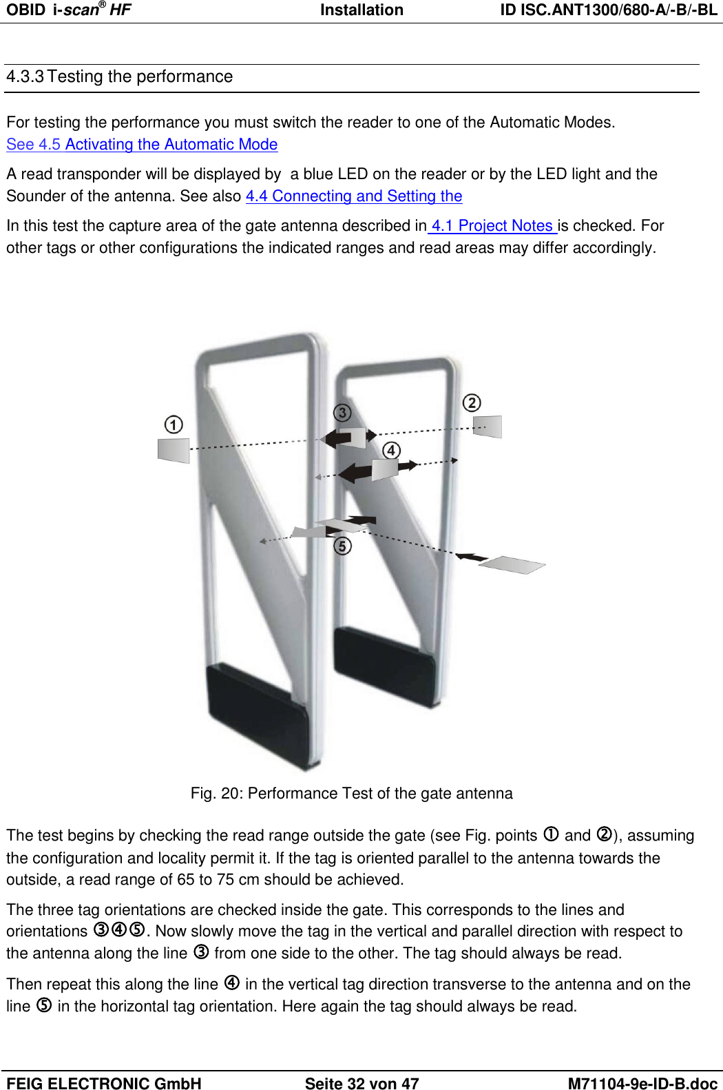
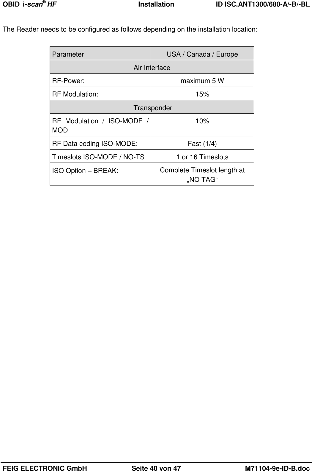
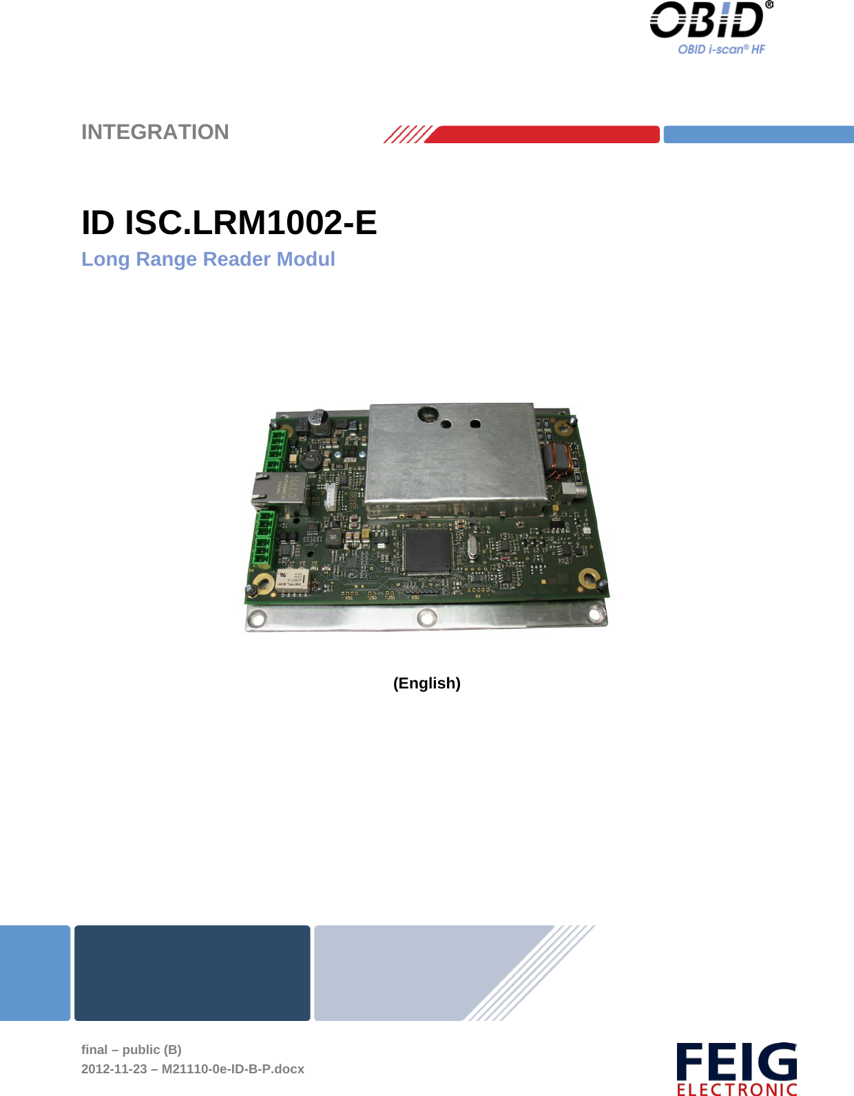
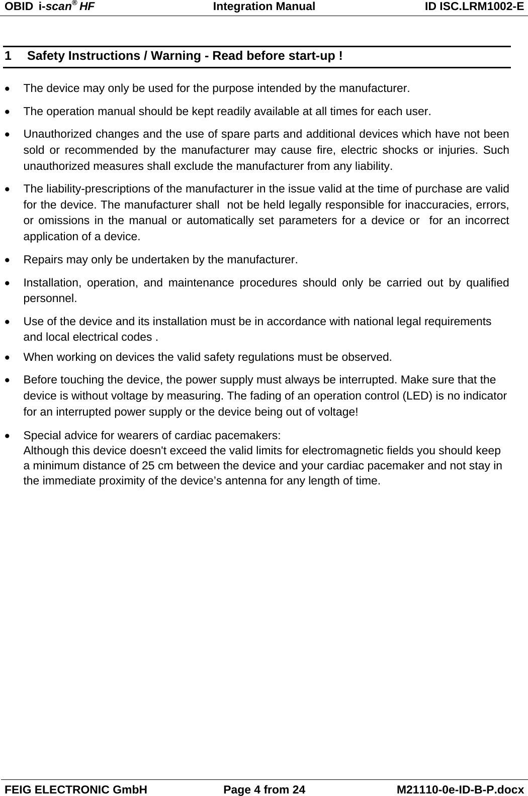
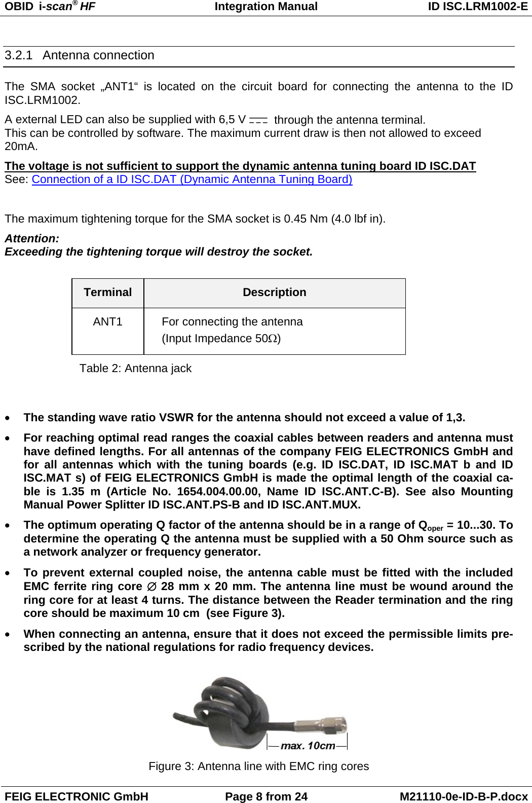
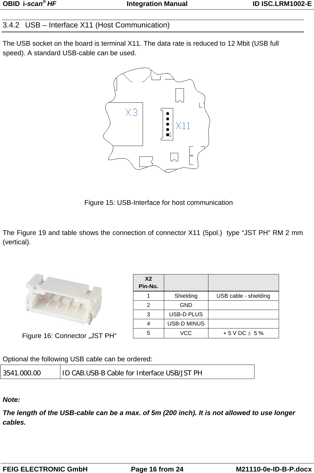
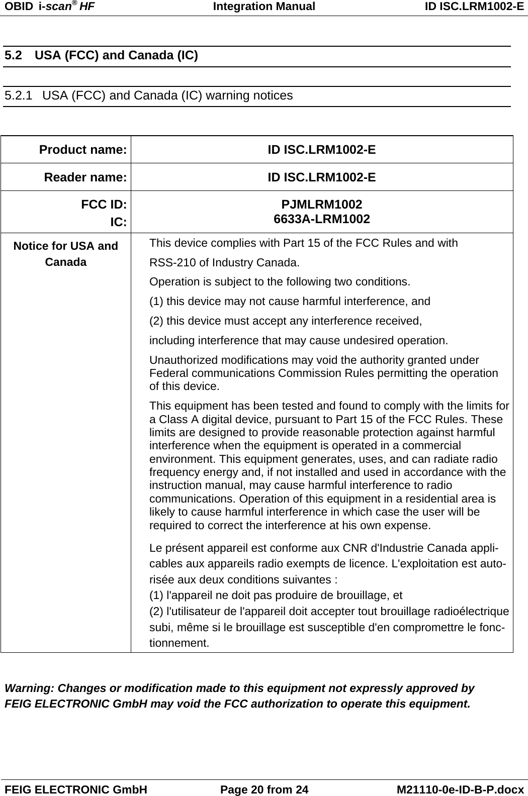
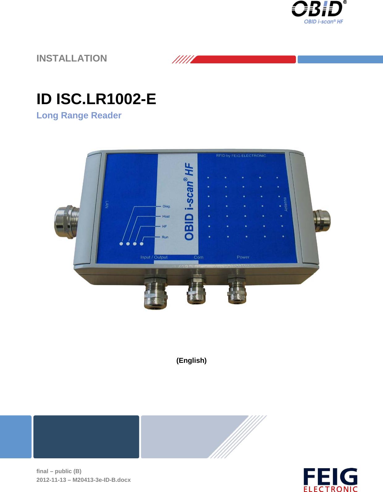
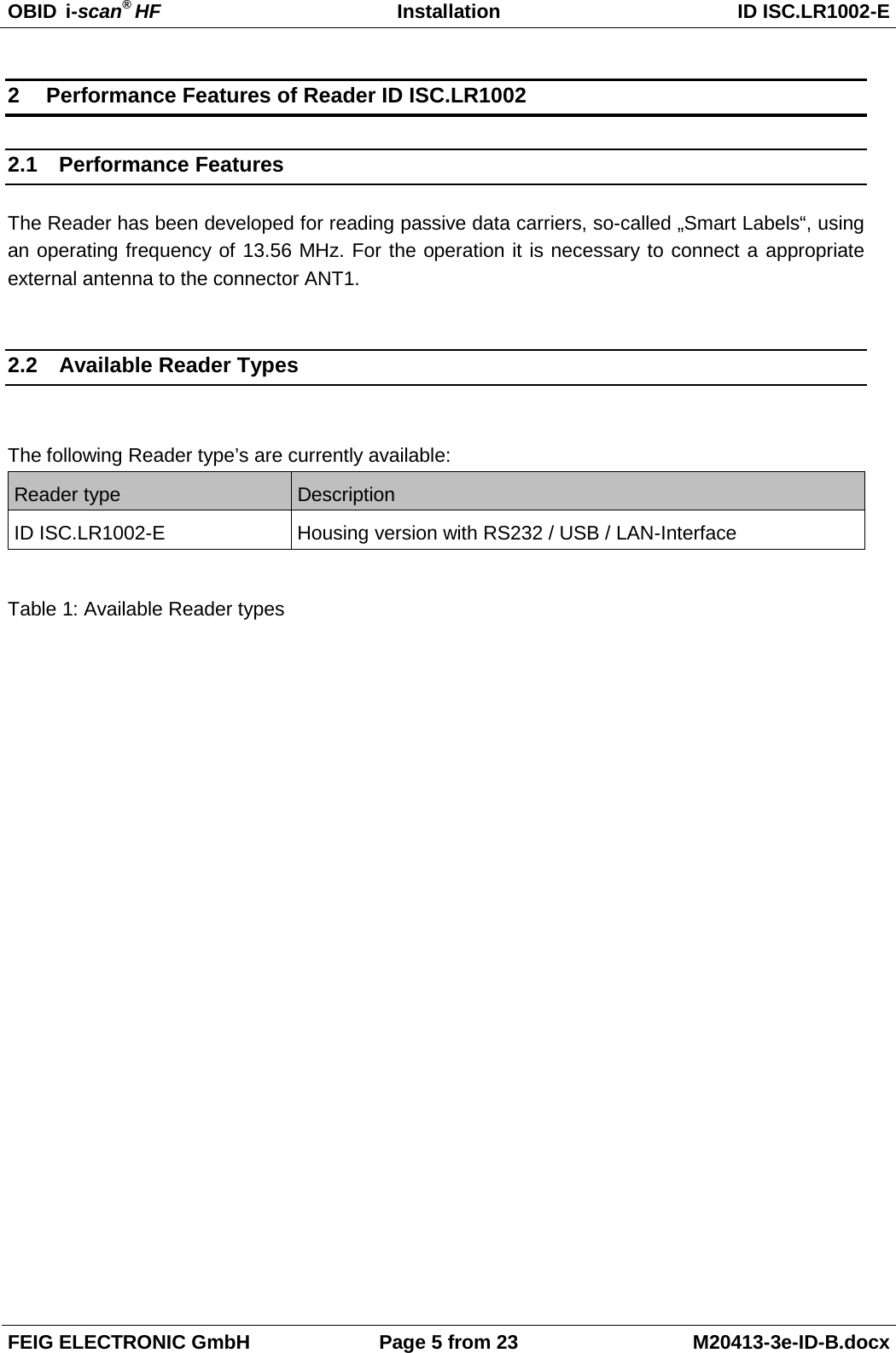
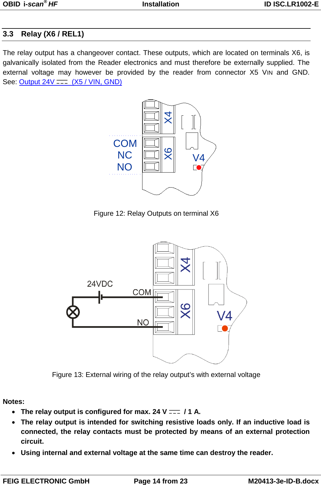
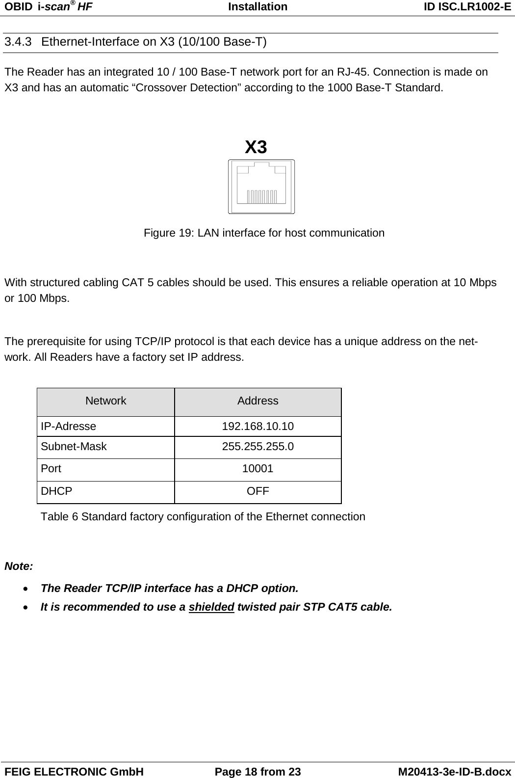
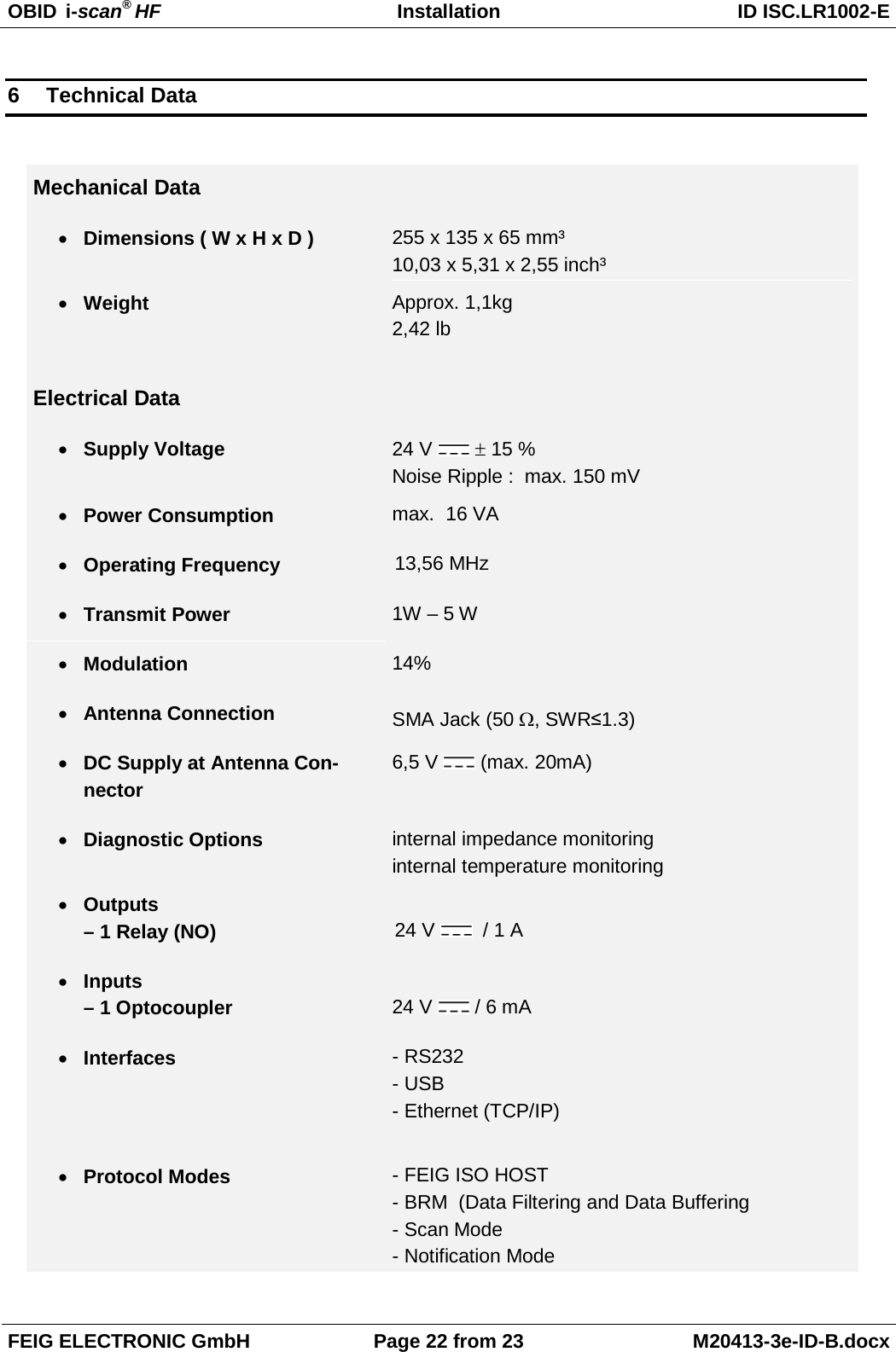
![OBID i-scan® HF Installation ID ISC.ANT1300/680-A/-B/-BL FEIG ELECTRONIC GmbH Seite 36 von 47 M71104-9e-ID-B.doc 7 Operating Mode If the alarm should occur by an EAS, you have to configure the reader as follow: Set “EAS” 8 Set by clicking on „Apply“ 4.4.3 Programming a Transponder with the AFI Byte If the Transponders will remain on the object when leaving the storage location, they must first be cancelled. This is generally done by writing to a particular area of the Transponder. The AFI byte (Application Family Identifier) is useful for this purpose, since it is contained in nearly all Transponder models in the ISO15693 family. To cancel, simply write a different code to the Transponder than for valid Transponders which trigger an alarm. Step Action: Note: 1 Select „Commands“ 2 Place the Transponder in the antenna field (Antenna 1) Select [0x01] Inventory Mode: New Inventory Requested 3 Read UID by clicking on „Send“ 4 The serial number, DSFID and Transponder type are displayed in a window. Write down the serial number of the Transponder](https://usermanual.wiki/Feig-Electronic/LRM1002.user-manual/User-Guide-1851272-Page-84.png)
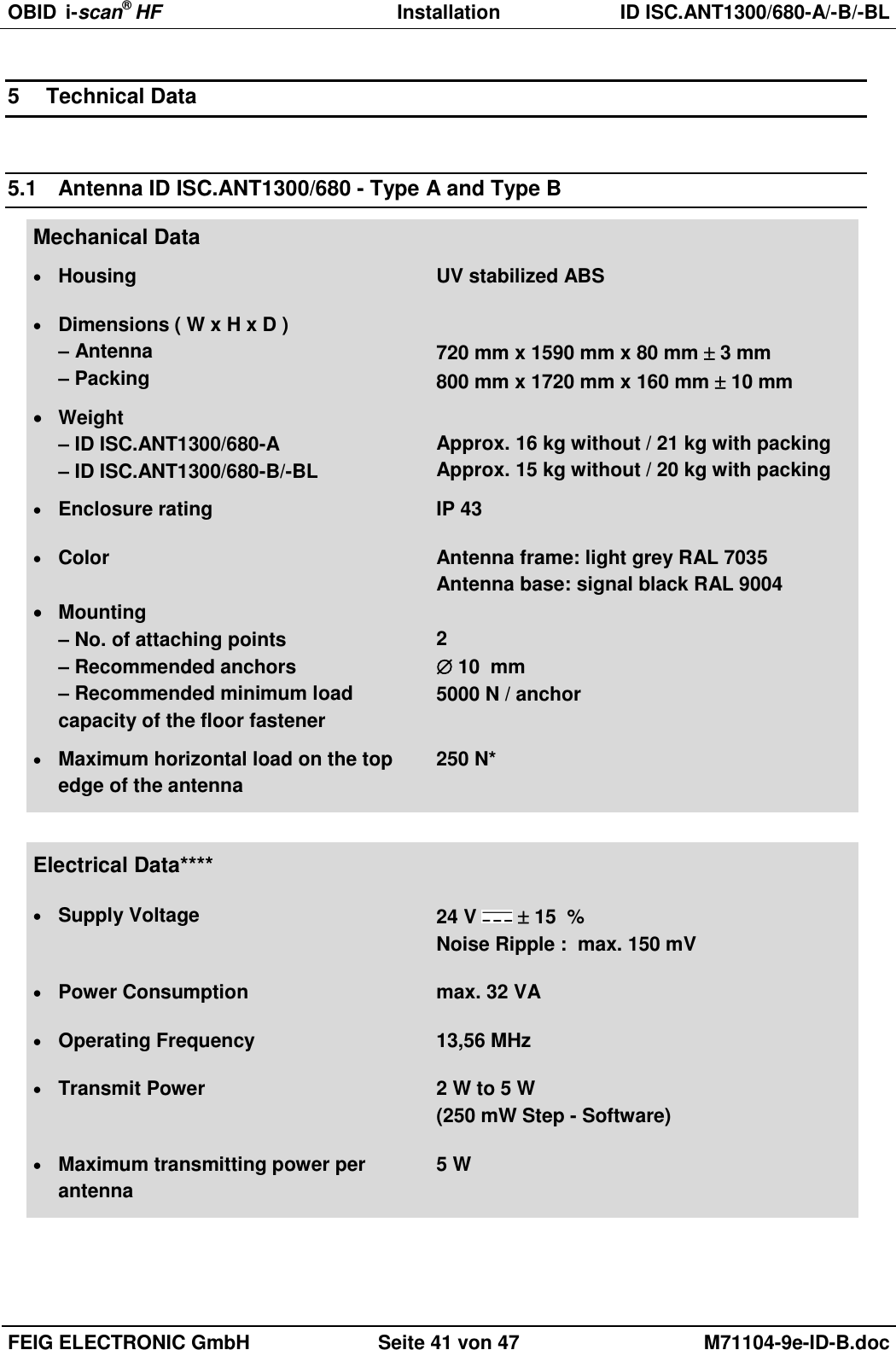
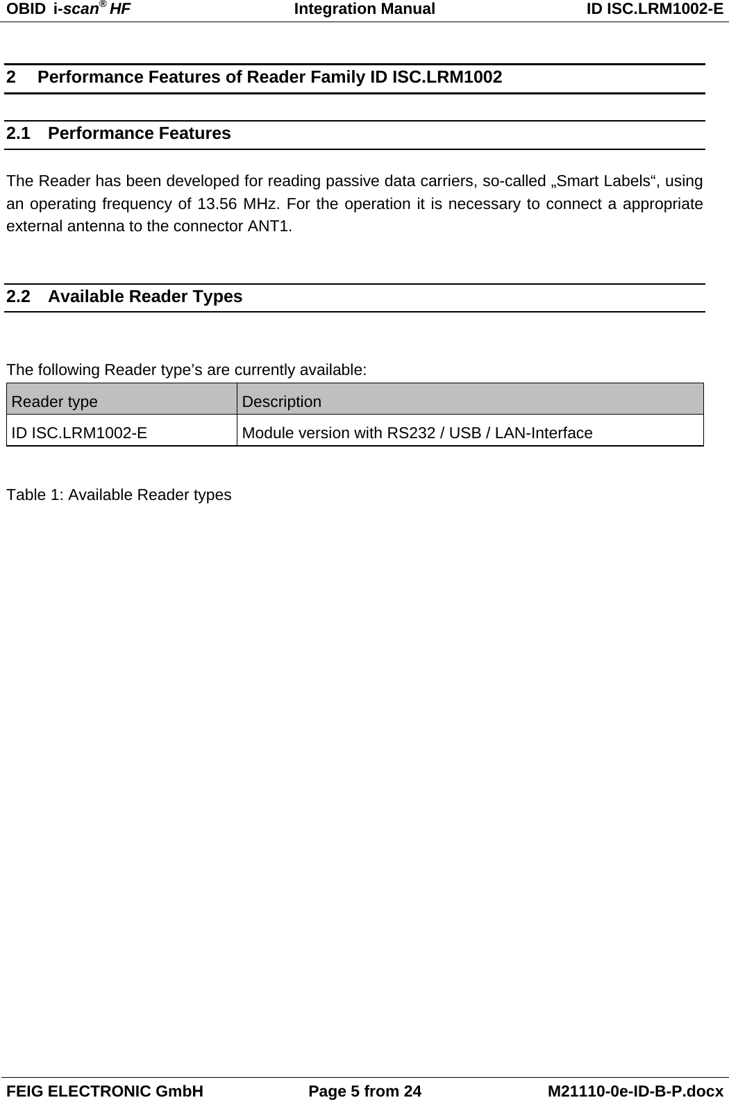
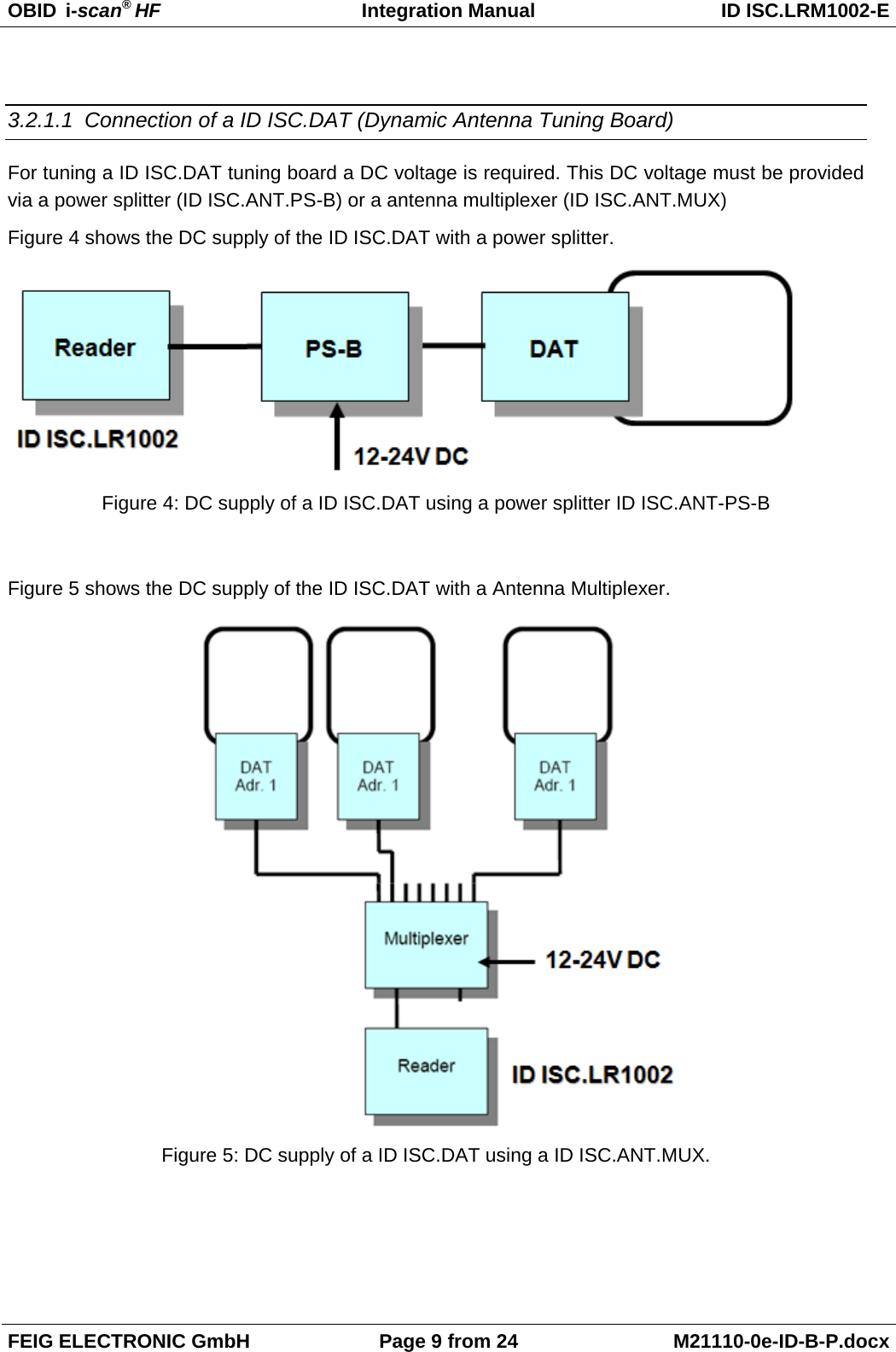
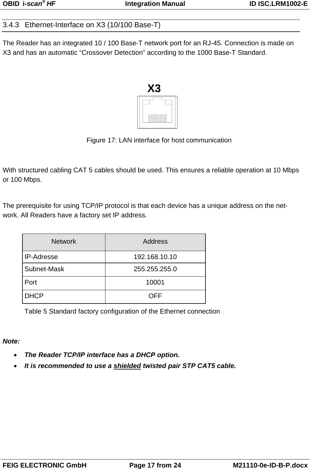
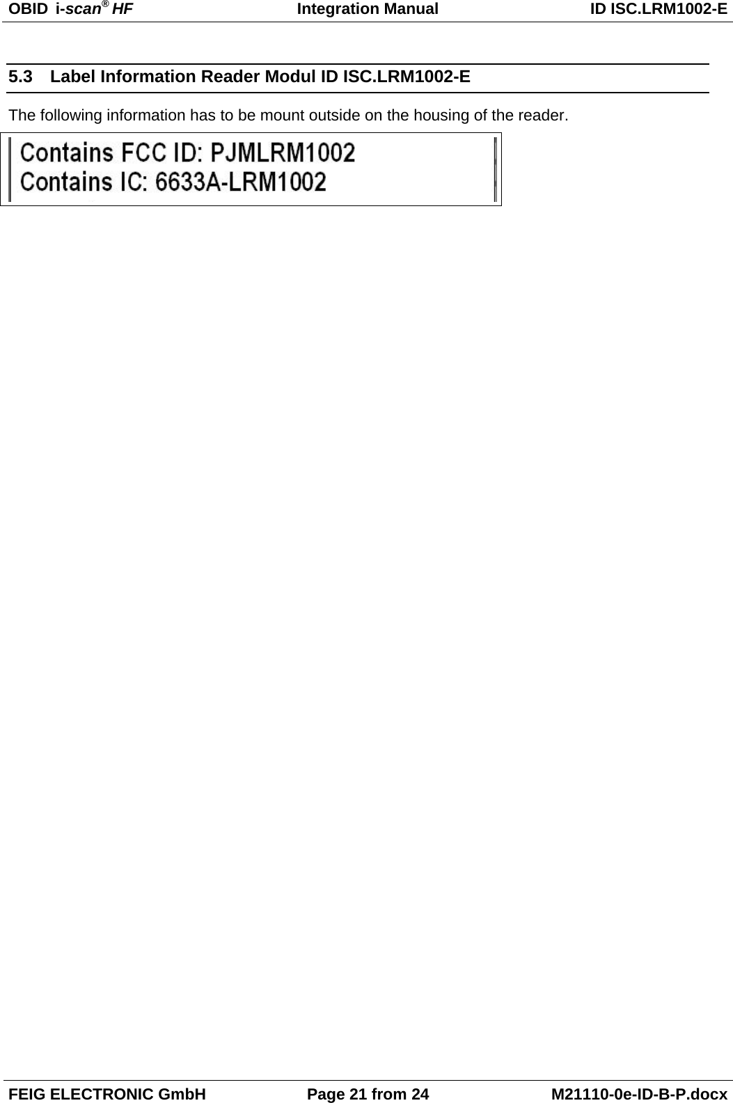
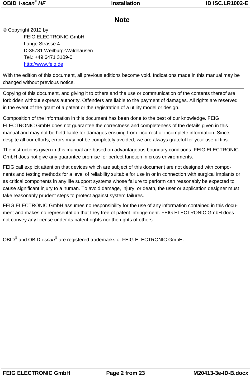
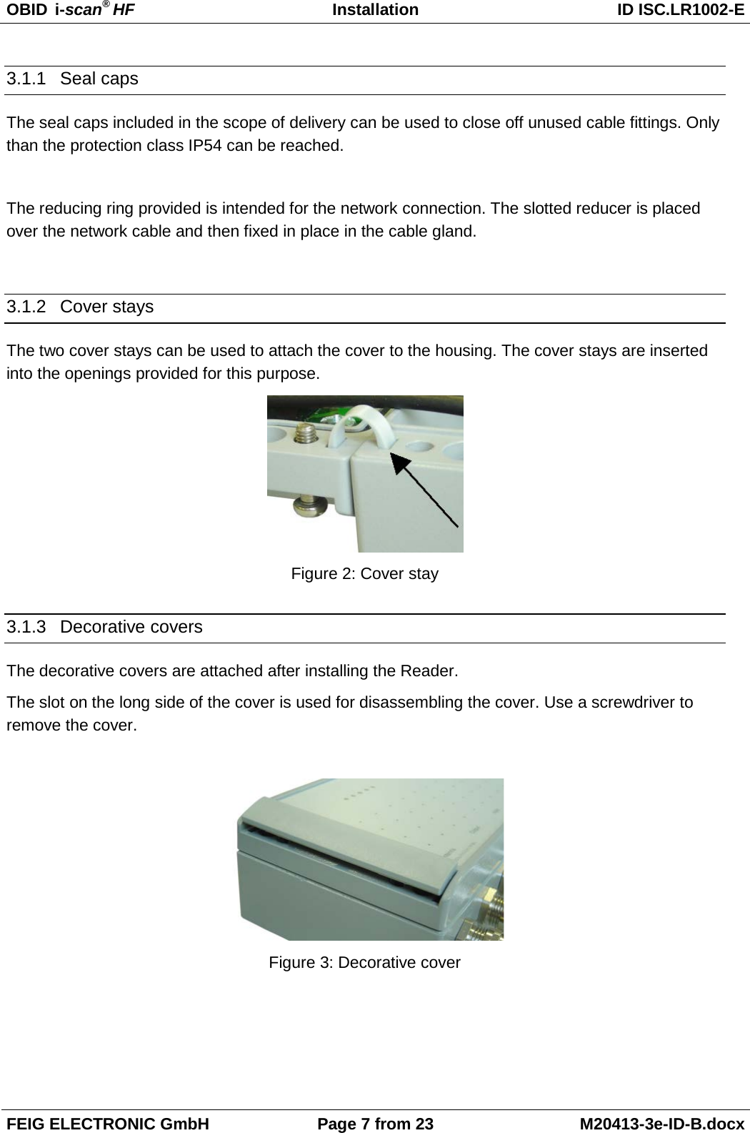
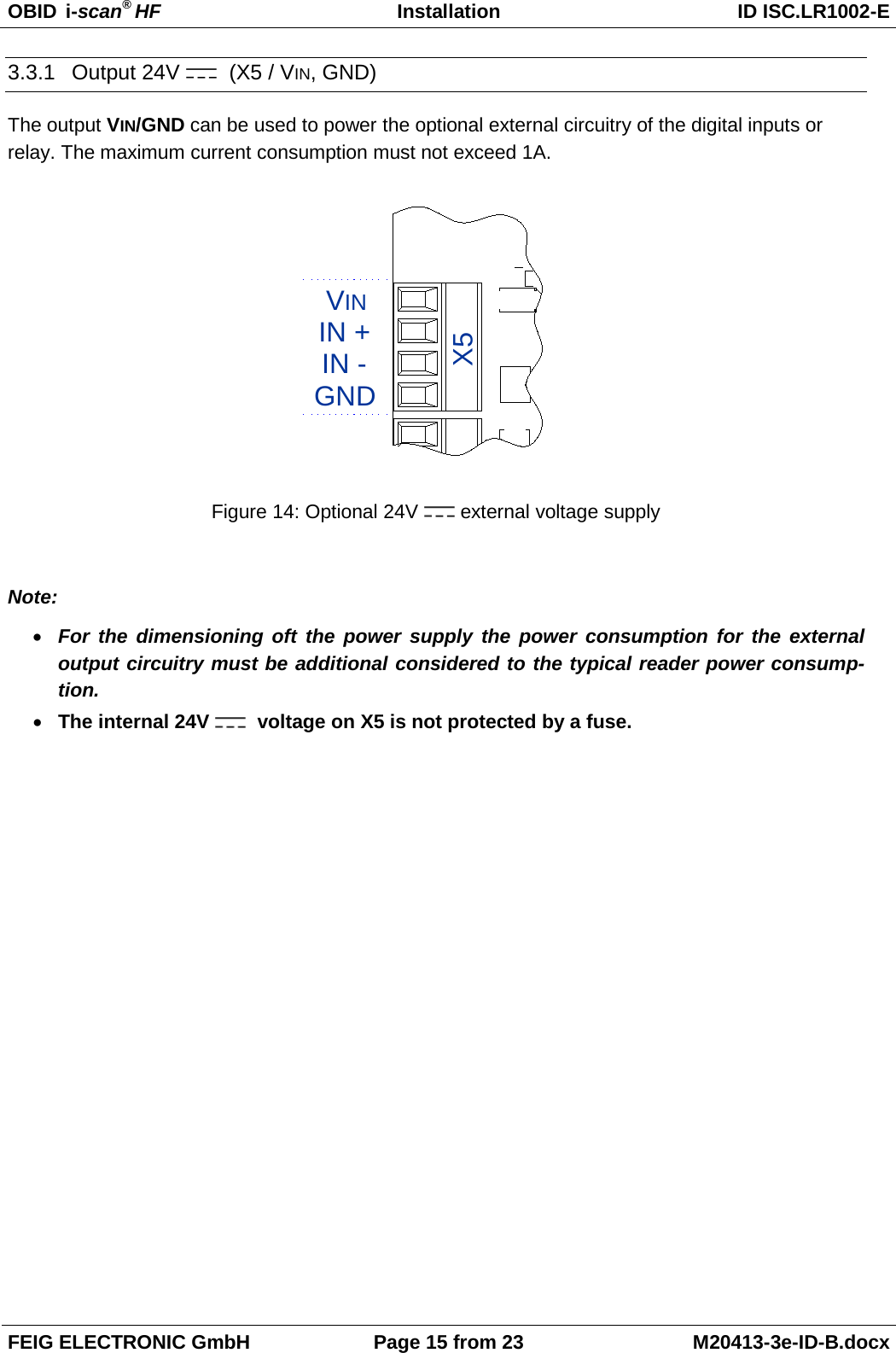
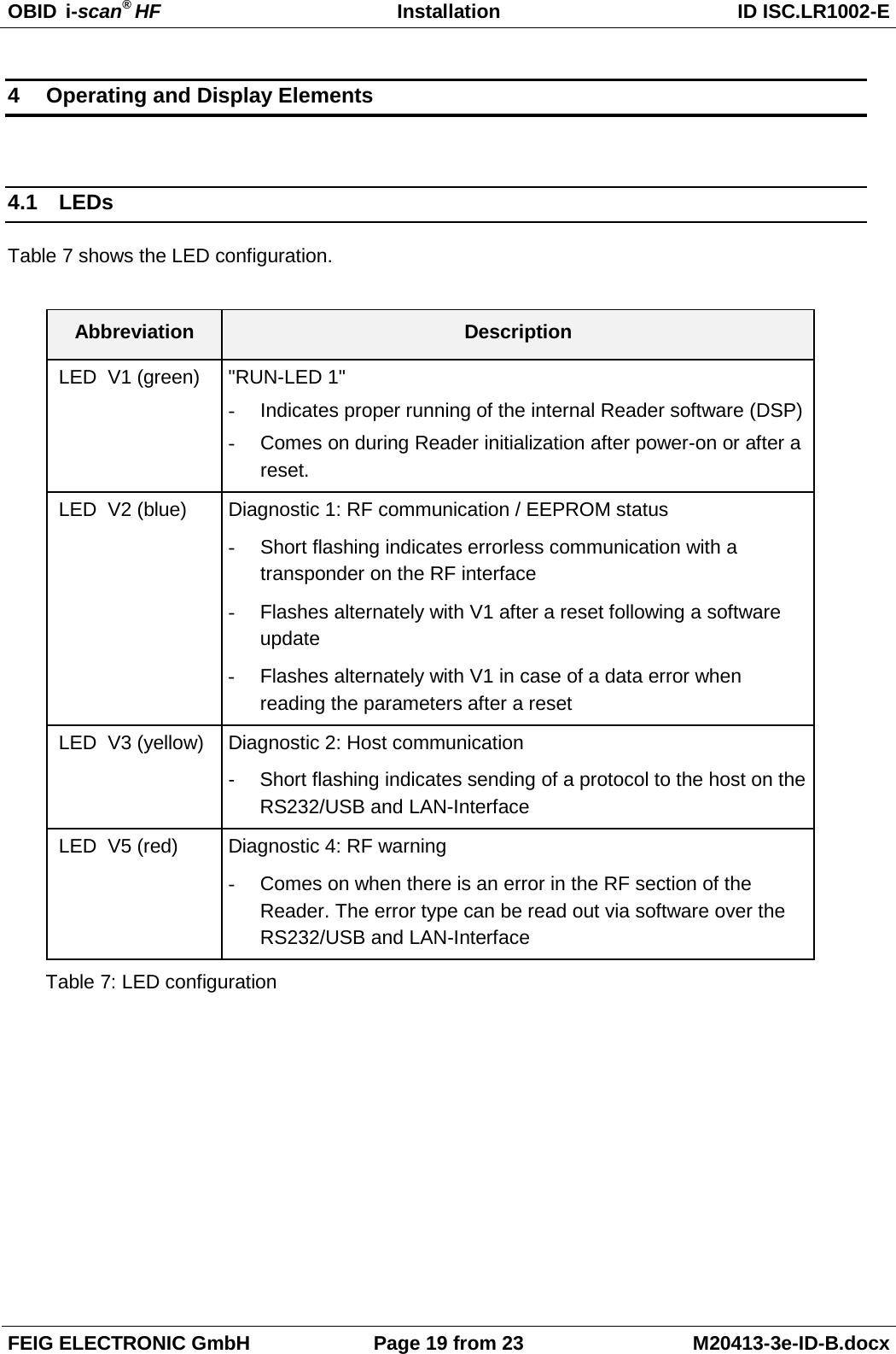
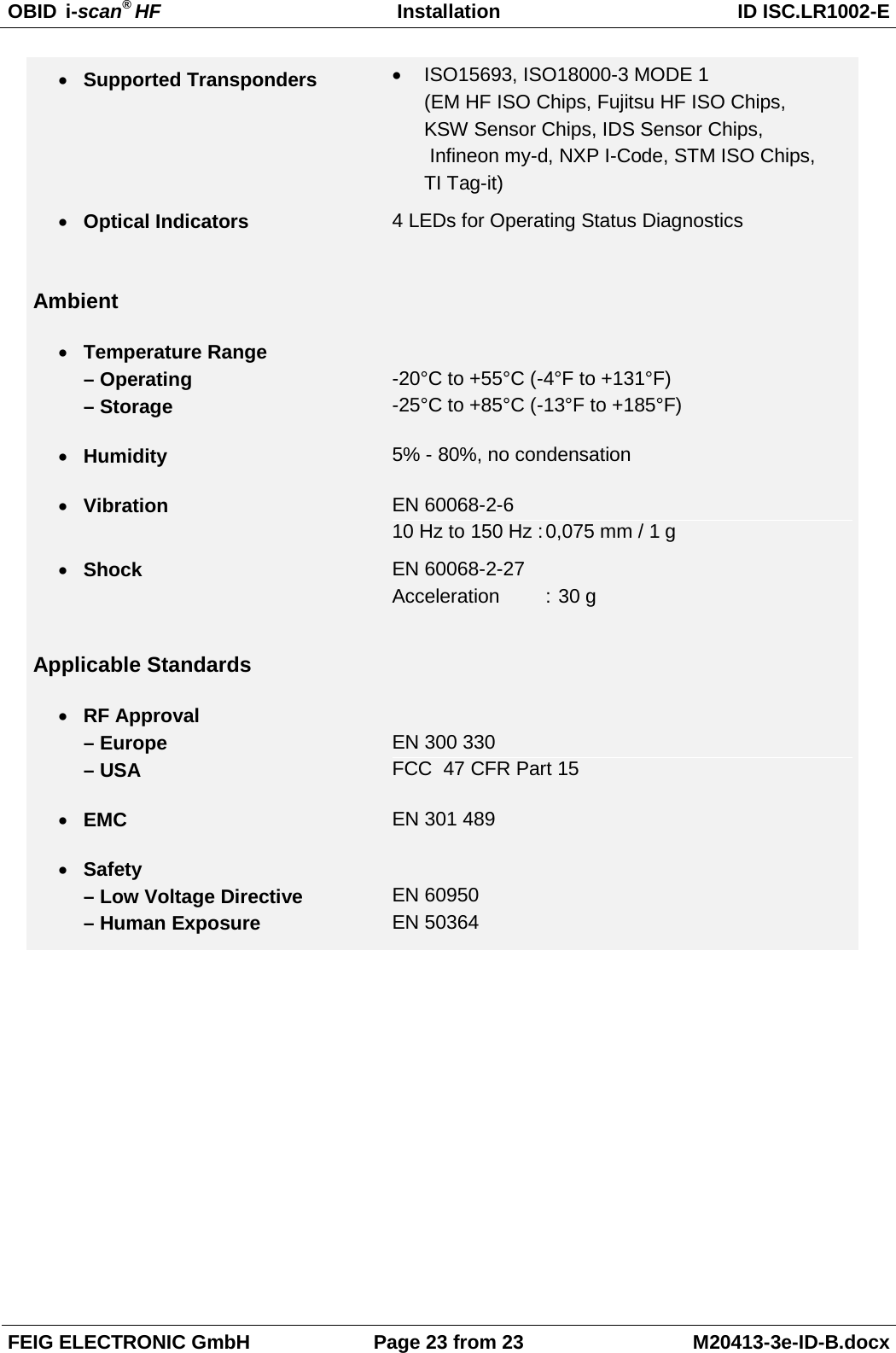
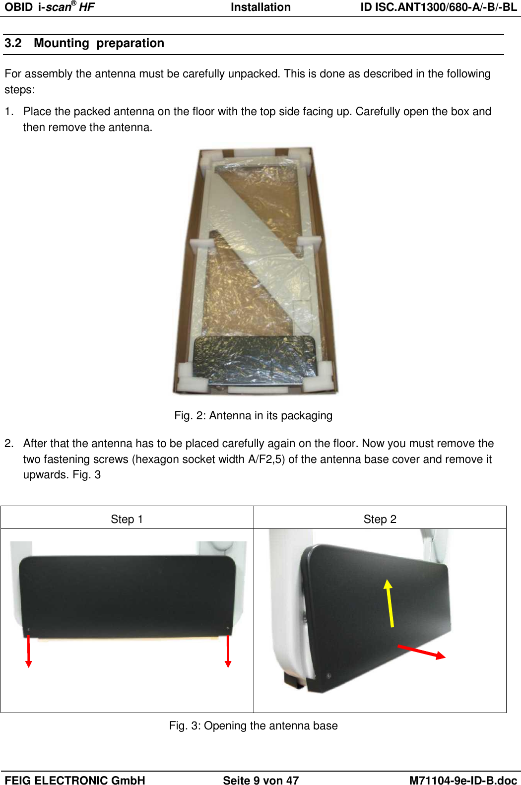
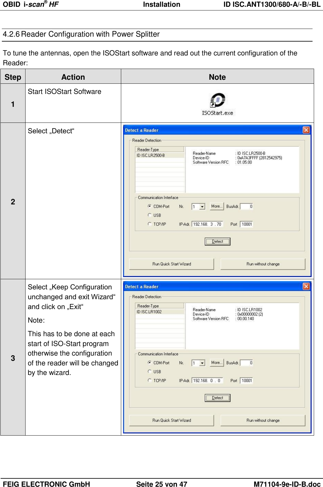
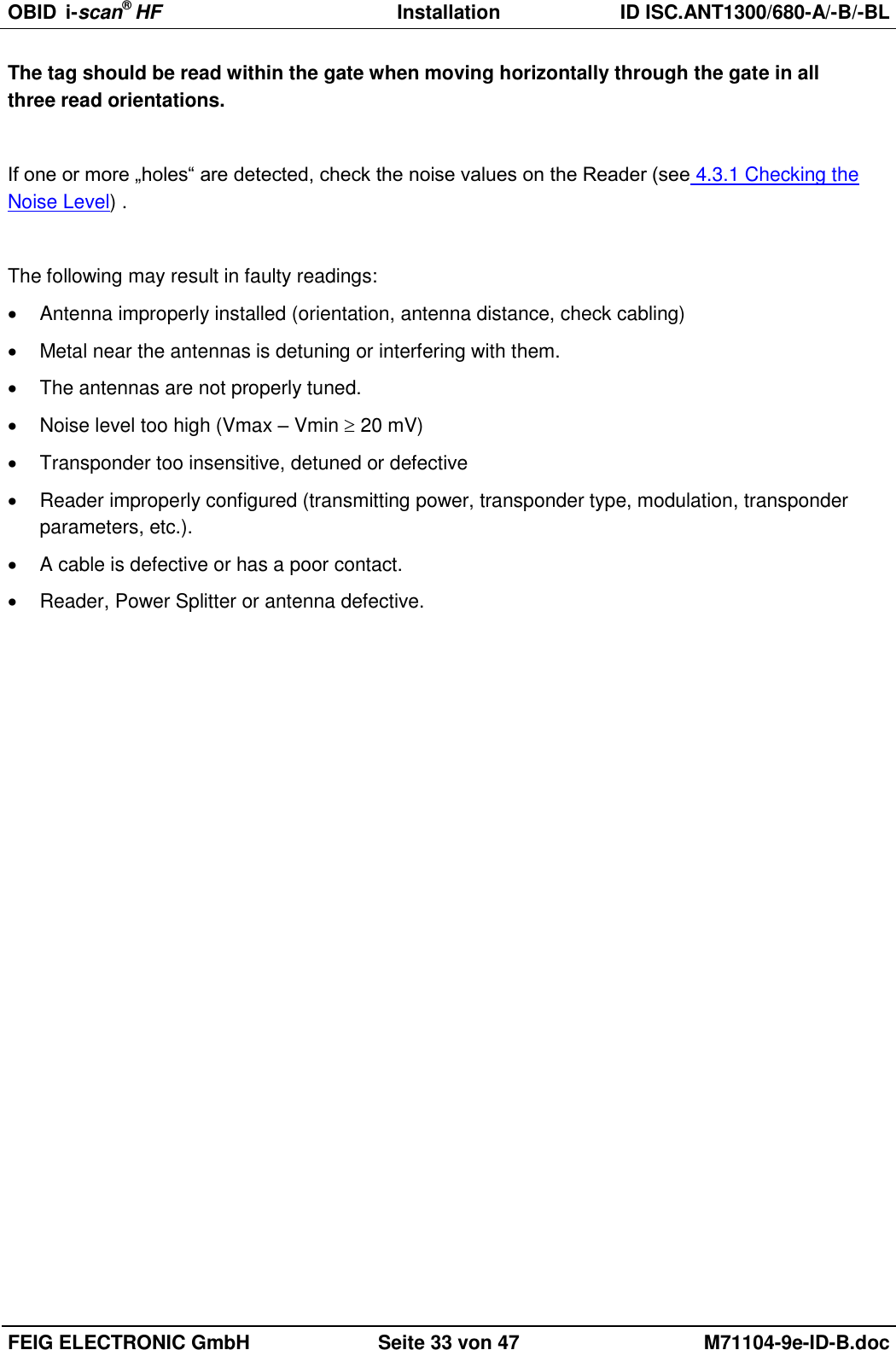
![OBID i-scan® HF Installation ID ISC.ANT1300/680-A/-B/-BL FEIG ELECTRONIC GmbH Seite 37 von 47 M71104-9e-ID-B.doc 5 Select „[0x27] Write AFI“ ADR: 1: addressed Serial Number: Select Transponder UID AFI: Desired AFI Number (not equal to 00) 6 Write AFI byte on to the transponder by click on „Send“ 7 To verify, read AFI byte by using the command [0x2B] Get System Information](https://usermanual.wiki/Feig-Electronic/LRM1002.user-manual/User-Guide-1851272-Page-85.png)