Feig Electronic LRM1002 RFID Reader User Manual
Feig Electronic GmbH RFID Reader
Contents
- 1. user manual
- 2. User manual
- 3. Users Manual
user manual

Date: 2012-06-11 Vers. no. 1.12
m. dudde hochfrequenz-technik
Rottland 5a
D-51429 Bergisch Gladbach/ Germany
Tel: +49 2207-96890
Fax +49 2207-968920
Annex no. 5
User Manual
INTEGRATION
final – public (B)
2012-11-23 – M21110-0e-ID-B-P.docx
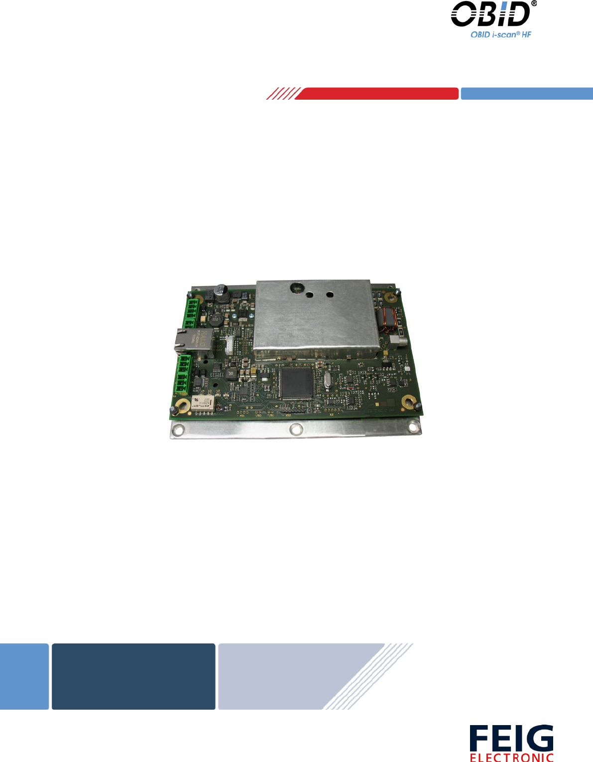
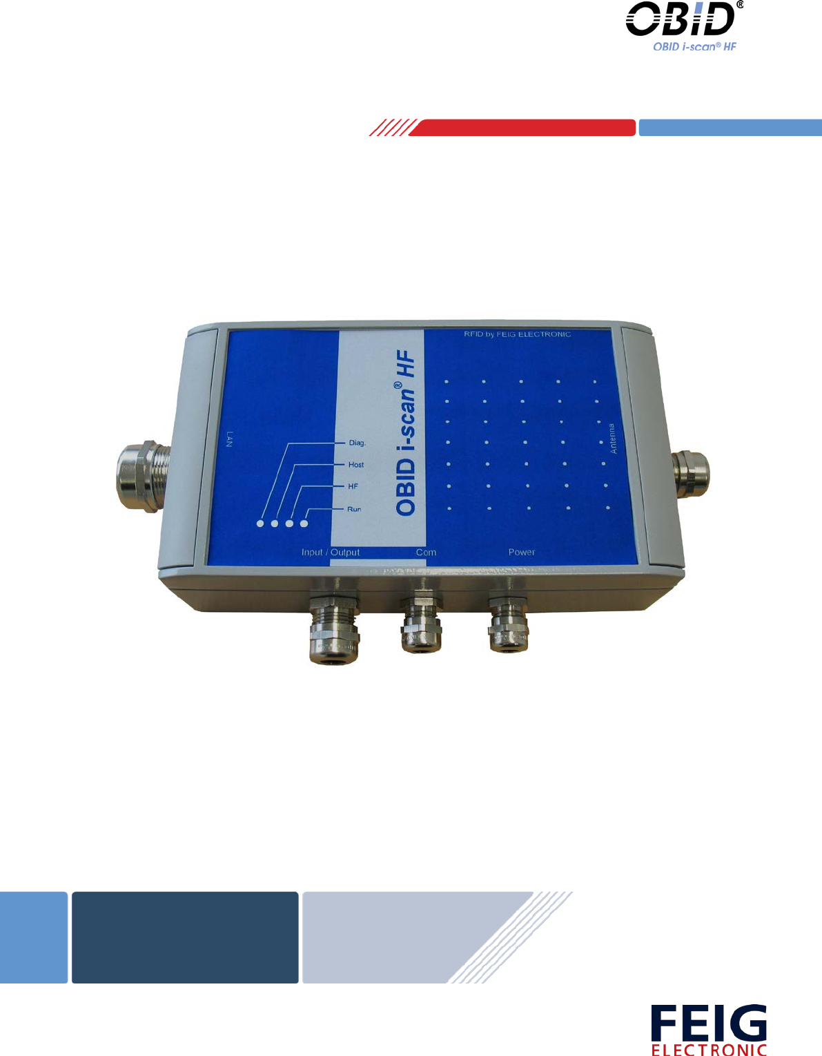
ID ISC.LRM1002-E
Long Range Reader Modul
(English)

OBID i-scan® HF Integration Manual ID ISC.LRM1002-E
FEIG ELECTRONIC GmbH Page 2 from 24 M21110-0e-ID-B-P.docx
Note
Copyright 2012 by
FEIG ELECTRONIC GmbH
Lange Strasse 4
D-35781 Weilburg-Waldhausen
Tel.: +49 6471 3109-0
http://www.feig.de
With the edition of this document, all previous editions become void. Indications made in this manual may be
changed without previous notice.
Copying of this document, and giving it to others and the use or communication of the contents thereof are
forbidden without express authority. Offenders are liable to the payment of damages. All rights are reserved
in the event of the grant of a patent or the registration of a utility model or design.
Composition of the information in this document has been done to the best of our knowledge. FEIG
ELECTRONIC GmbH does not guarantee the correctness and completeness of the details given in this
manual and may not be held liable for damages ensuing from incorrect or incomplete information. Since,
despite all our efforts, errors may not be completely avoided, we are always grateful for your useful tips.
The instructions given in this manual are based on advantageous boundary conditions. FEIG ELECTRONIC
GmbH does not give any guarantee promise for perfect function in cross environments.
FEIG call explicit attention that devices which are subject of this document are not designed with compo-
nents and testing methods for a level of reliability suitable for use in or in connection with surgical implants or
as critical components in any life support systems whose failure to perform can reasonably be expected to
cause significant injury to a human. To avoid damage, injury, or death, the user or application designer must
take reasonably prudent steps to protect against system failures.
FEIG ELECTRONIC GmbH assumes no responsibility for the use of any information contained in this docu-
ment and makes no representation that they free of patent infringement. FEIG ELECTRONIC GmbH does
not convey any license under its patent rights nor the rights of others.
OBID® and OBID i-scan® are registered trademarks of FEIG ELECTRONIC GmbH.

OBID i-scan® HF Integration Manual ID ISC.LRM1002-E
FEIG ELECTRONIC GmbH Page 3 from 24 M21110-0e-ID-B-P.docx
Content
1 Safety Instructions / Warning - Read before start-up ! 4
2 Performance Features of Reader Family ID ISC.LRM1002 5
2.1 Performance Features .................................................................................................. 5
2.2 Available Reader Types ................................................................................................ 5
3 Installation and mounting 6
3.1 Mounting ID ISC.LRM1002-E ........................................................................................ 6
3.2 Terminals ....................................................................................................................... 7
3.2.1 Antenna connection .................................................................................................... 8
3.2.1.1 Connection of a ID ISC.DAT (Dynamic Antenna Tuning Board) ....................... 9
3.2.2 Supply voltage .......................................................................................................... 10
3.2.3 OptocouplerInputs (X5 / IN1) .................................................................................... 11
3.3 Relay (X6 / REL1) ......................................................................................................... 13
3.3.1 Output 24V (X5 / VIN, GND) ............................................................................. 14
3.4 Interfaces ..................................................................................................................... 15
3.4.1 RS232-Interface X4 .................................................................................................. 15
3.4.2 USB – Interface X11 (Host Communication) ............................................................ 16
3.4.3 Ethernet-Interface on X3 (10/100 Base-T) ................................................................ 17
4 Operating and Display Elements 18
4.1 LEDs ............................................................................................................................. 18
5 Radio Approvals 19
5.1 Europe (CE) .................................................................................................................. 19
5.2 USA (FCC) and Canada (IC) ........................................................................................ 20
6 Technical Data 23

OBID i-scan® HF Integration Manual ID ISC.LRM1002-E
FEIG ELECTRONIC GmbH Page 4 from 24 M21110-0e-ID-B-P.docx
1 Safety Instructions / Warning - Read before start-up !
• The device may only be used for the purpose intended by the manufacturer.
• The operation manual should be kept readily available at all times for each user.
• Unauthorized changes and the use of spare parts and additional devices which have not been
sold or recommended by the manufacturer may cause fire, electric shocks or injuries. Such
unauthorized measures shall exclude the manufacturer from any liability.
• The liability-prescriptions of the manufacturer in the issue valid at the time of purchase are valid
for the device. The manufacturer shall not be held legally responsible for inaccuracies, errors,
or omissions in the manual or automatically set parameters for a device or for an incorrect
application of a device.
• Repairs may only be undertaken by the manufacturer.
• Installation, operation, and maintenance procedures should only be carried out by qualified
personnel.
• Use of the device and its installation must be in accordance with national legal requirements
and local electrical codes .
• When working on devices the valid safety regulations must be observed.
• Before touching the device, the power supply must always be interrupted. Make sure that the
device is without voltage by measuring. The fading of an operation control (LED) is no indicator
for an interrupted power supply or the device being out of voltage!
• Special advice for wearers of cardiac pacemakers:
Although this device doesn't exceed the valid limits for electromagnetic fields you should keep
a minimum distance of 25 cm between the device and your cardiac pacemaker and not stay in
the immediate proximity of the device’s antenna for any length of time.

OBID i-scan® HF Integration Manual ID ISC.LRM1002-E
FEIG ELECTRONIC GmbH Page 5 from 24 M21110-0e-ID-B-P.docx
2 Performance Features of Reader Family ID ISC.LRM1002
2.1 Performance Features
The Reader has been developed for reading passive data carriers, so-called „Smart Labels“, using
an operating frequency of 13.56 MHz. For the operation it is necessary to connect a appropriate
external antenna to the connector ANT1.
2.2 Available Reader Types
The following Reader type’s are currently available:
Reader type Description
ID ISC.LRM1002-E Module version with RS232 / USB / LAN-Interface
Table 1: Available Reader types
OBID i-scan® HF Integration Manual ID ISC.LRM1002-E
FEIG ELECTRONIC GmbH Page 6 from 24 M21110-0e-ID-B-P.docx
3 Installation and mounting
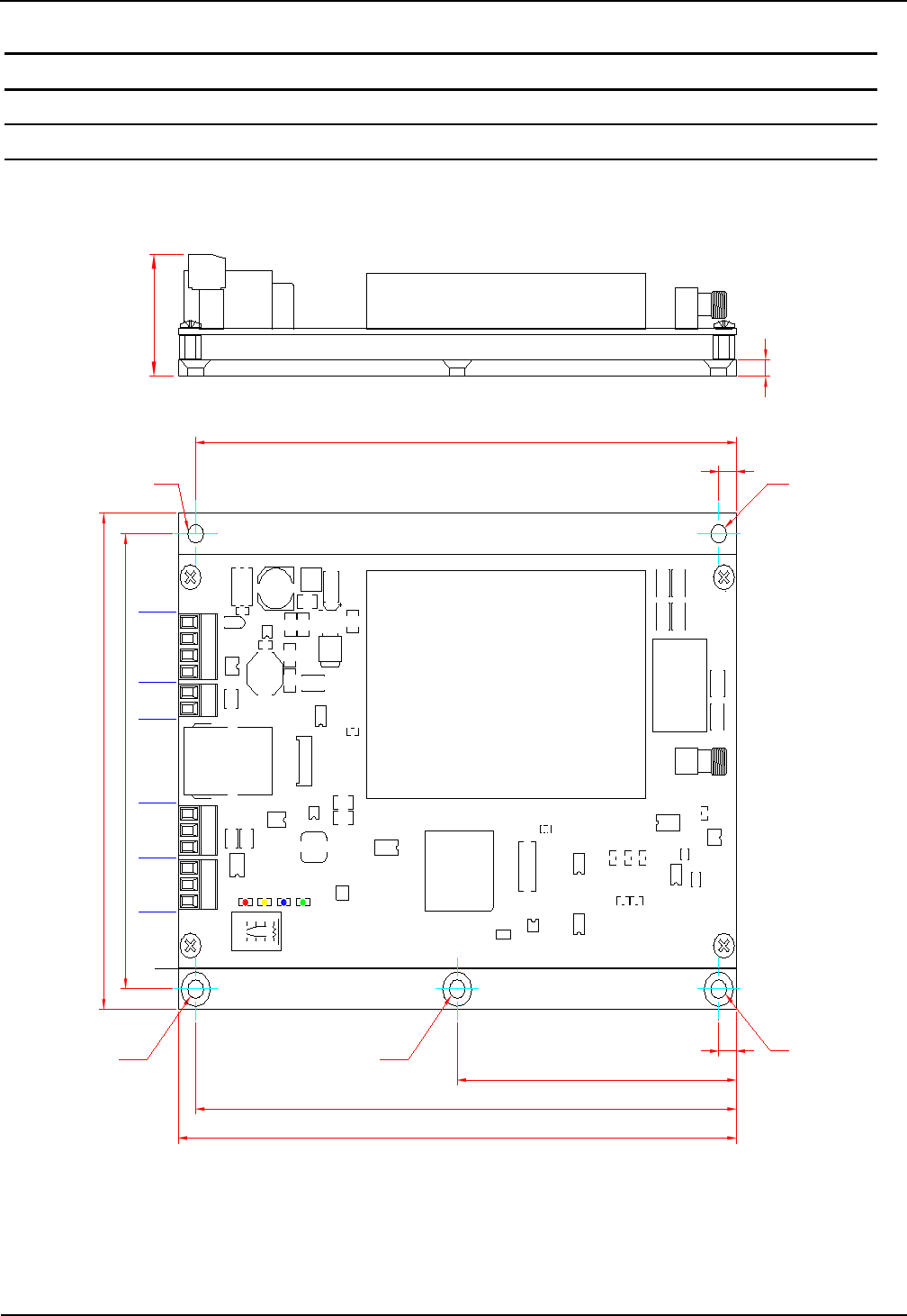
3.1 Mounting ID ISC.LRM1002-E
The Reader Module is designed for installation on a heat sink. Mounting is accomplished using the
∅ 4.5 mm holes located on the base plate (see: Figure 1).
120
110
ø 4,5 mm*
160
155
80
ø 4,5 mm* ø 4,5 mm*
5
ø 4,5 mm
155
ø 4,5 mm
5
4
29
V3 V2 V1
V4
NO
NC
COM
TxD
RxD
GND
GND
V
IN
GND
V
IN
IN -
IN +
X1 X5
X4
X6
X11
X3
ANT1
Figure 1: Scale drawing oft the Reader module ID ISC.LRM1002-E with mounting plate
OBID i-scan® HF Integration Manual ID ISC.LRM1002-E
FEIG ELECTRONIC GmbH Page 7 from 24 M21110-0e-ID-B-P.docx
To fully exploit the performance of the Reader Module, the heat sink should have a thermal re-
sistance RThK of max. 2 K/W. When attaching the Reader Module to the heat sink you should strive
for a little heat transfer resistance between the base plate and the heat sink as possible. The use
of heat sink compound is recommended.
If the antenna is properly tuned and there is sufficient air convection along the mounting plate, the
ID ISC.LRM1002-E can be operated without an additional heat sink at up to 2W of power. Note
here however that detuning of the antenna can result in additional heating of the Reader. In such
cases the Reader regulates its output power down until the upper temperature limit of its final stage
fallen down again.
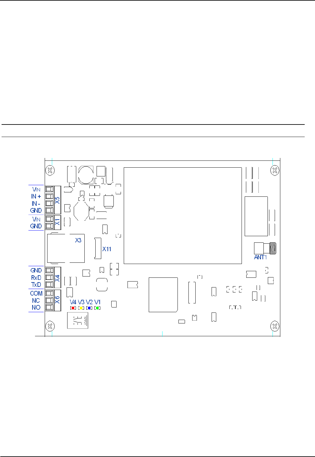
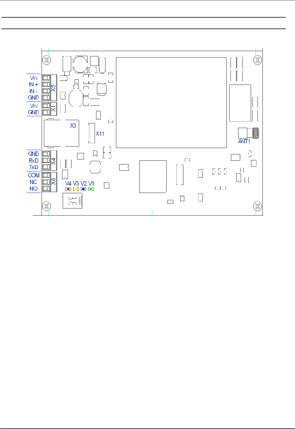
3.2 Terminals
Figure 5 shows the terminals and control elements of the ID ISC.LR(M)1002-E
Figure 2: Reader terminals
OBID i-scan® HF Integration Manual ID ISC.LRM1002-E
FEIG ELECTRONIC GmbH Page 8 from 24 M21110-0e-ID-B-P.docx
3.2.1 Antenna connection
The SMA socket „ANT1“ is located on the circuit board for connecting the antenna to the ID
ISC.LRM1002.
A external LED can also be supplied with 6,5 V through the antenna terminal.
This can be controlled by software. The maximum current draw is then not allowed to exceed
20mA.
The voltage is not sufficient to support the dynamic antenna tuning board ID ISC.DAT
See: Connection of a ID ISC.DAT (Dynamic Antenna Tuning Board)
The maximum tightening torque for the SMA socket is 0.45 Nm (4.0 lbf in).
Attention:
Exceeding the tightening torque will destroy the socket.
Terminal Description
ANT1 For connecting the antenna
(Input Impedance 50Ω)
Table 2: Antenna jack
• The standing wave ratio VSWR for the antenna should not exceed a value of 1,3.
• For reaching optimal read ranges the coaxial cables between readers and antenna must
have defined lengths. For all antennas of the company FEIG ELECTRONICS GmbH and
for all antennas which with the tuning boards (e.g. ID ISC.DAT, ID ISC.MAT b and ID
ISC.MAT s) of FEIG ELECTRONICS GmbH is made the optimal length of the coaxial ca-
ble is 1.35 m (Article No. 1654.004.00.00, Name ID ISC.ANT.C-B). See also Mounting
Manual Power Splitter ID ISC.ANT.PS-B and ID ISC.ANT.MUX.
• The optimum operating Q factor of the antenna should be in a range of Qoper = 10...30. To
determine the operating Q the antenna must be supplied with a 50 Ohm source such as
a network analyzer or frequency generator.
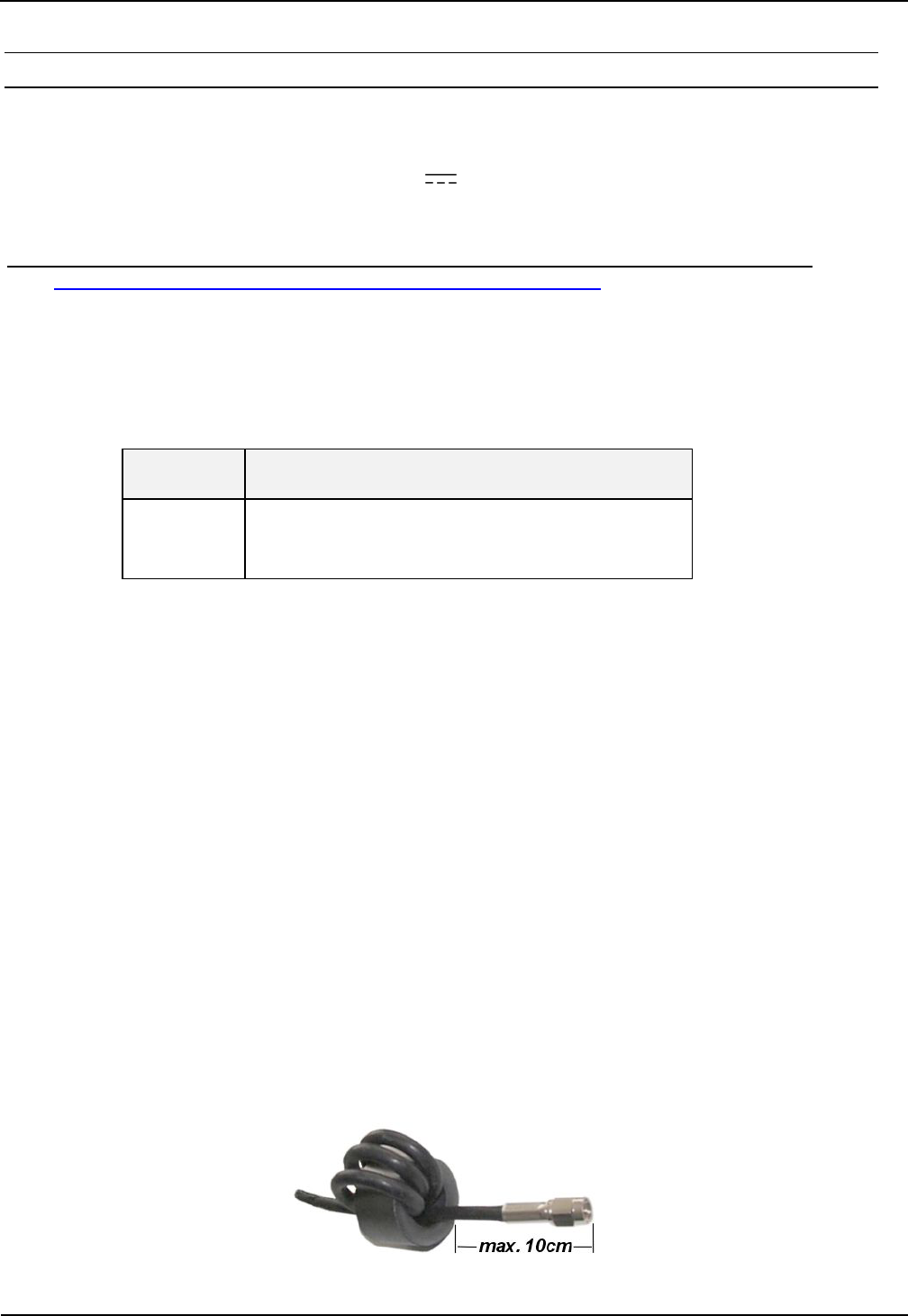
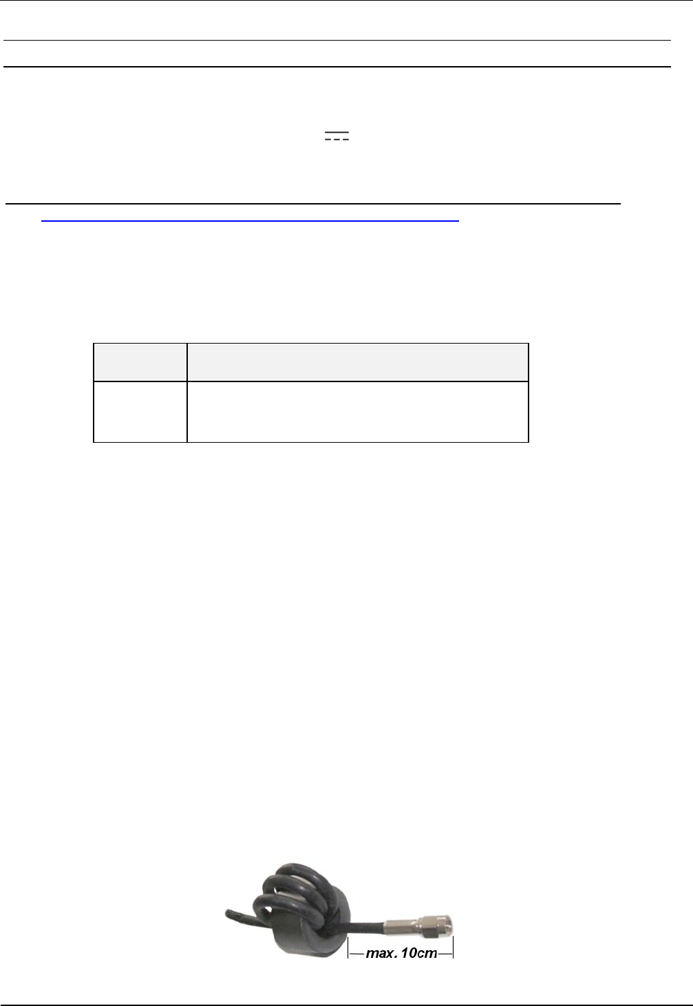
• To prevent external coupled noise, the antenna cable must be fitted with the included
EMC ferrite ring core ∅ 28 mm x 20 mm. The antenna line must be wound around the
ring core for at least 4 turns. The distance between the Reader termination and the ring
core should be maximum 10 cm (see Figure 3).
• When connecting an antenna, ensure that it does not exceed the permissible limits pre-
scribed by the national regulations for radio frequency devices.
Figure 3: Antenna line with EMC ring cores
OBID i-scan® HF Integration Manual ID ISC.LRM1002-E
FEIG ELECTRONIC GmbH Page 9 from 24 M21110-0e-ID-B-P.docx
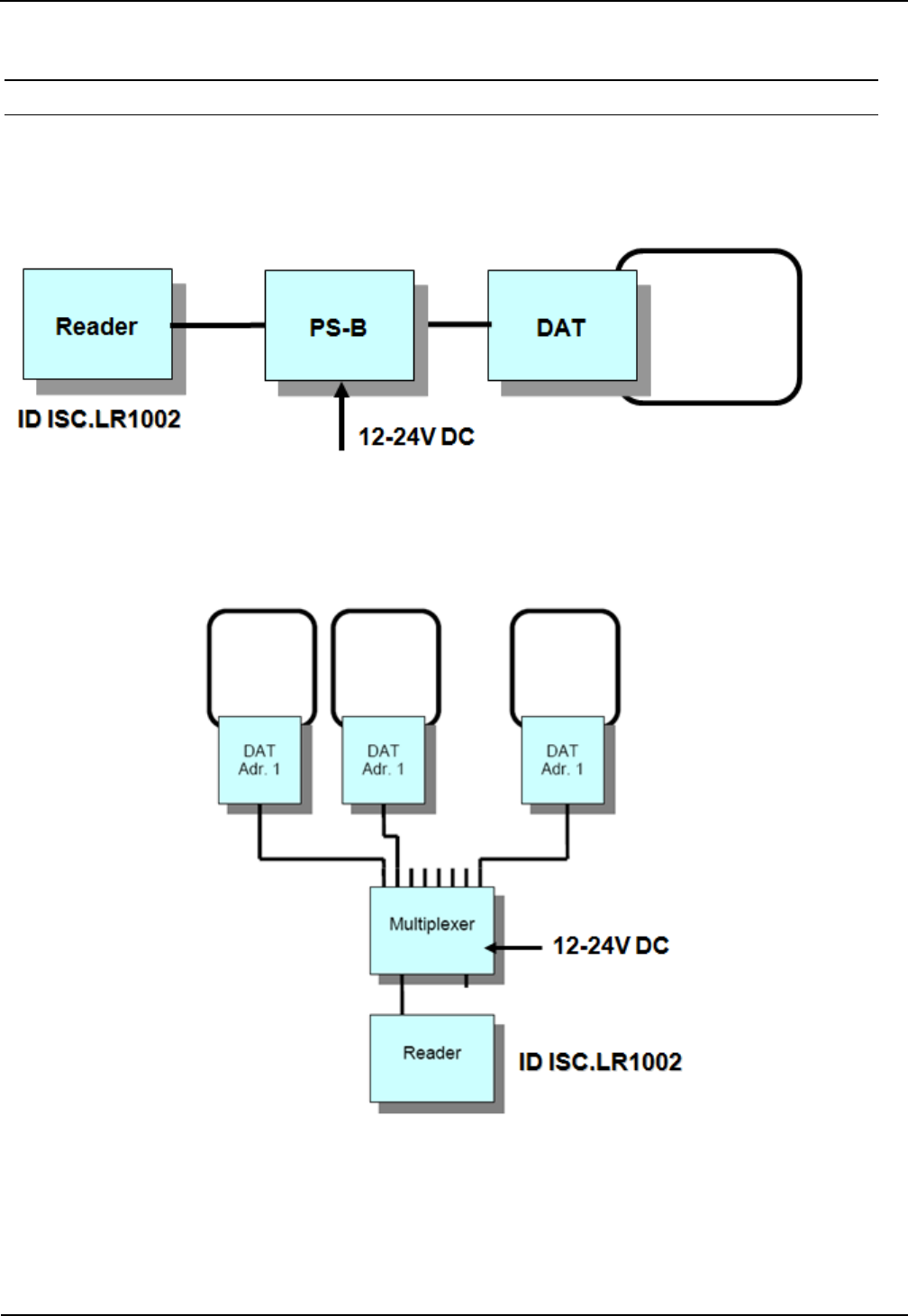
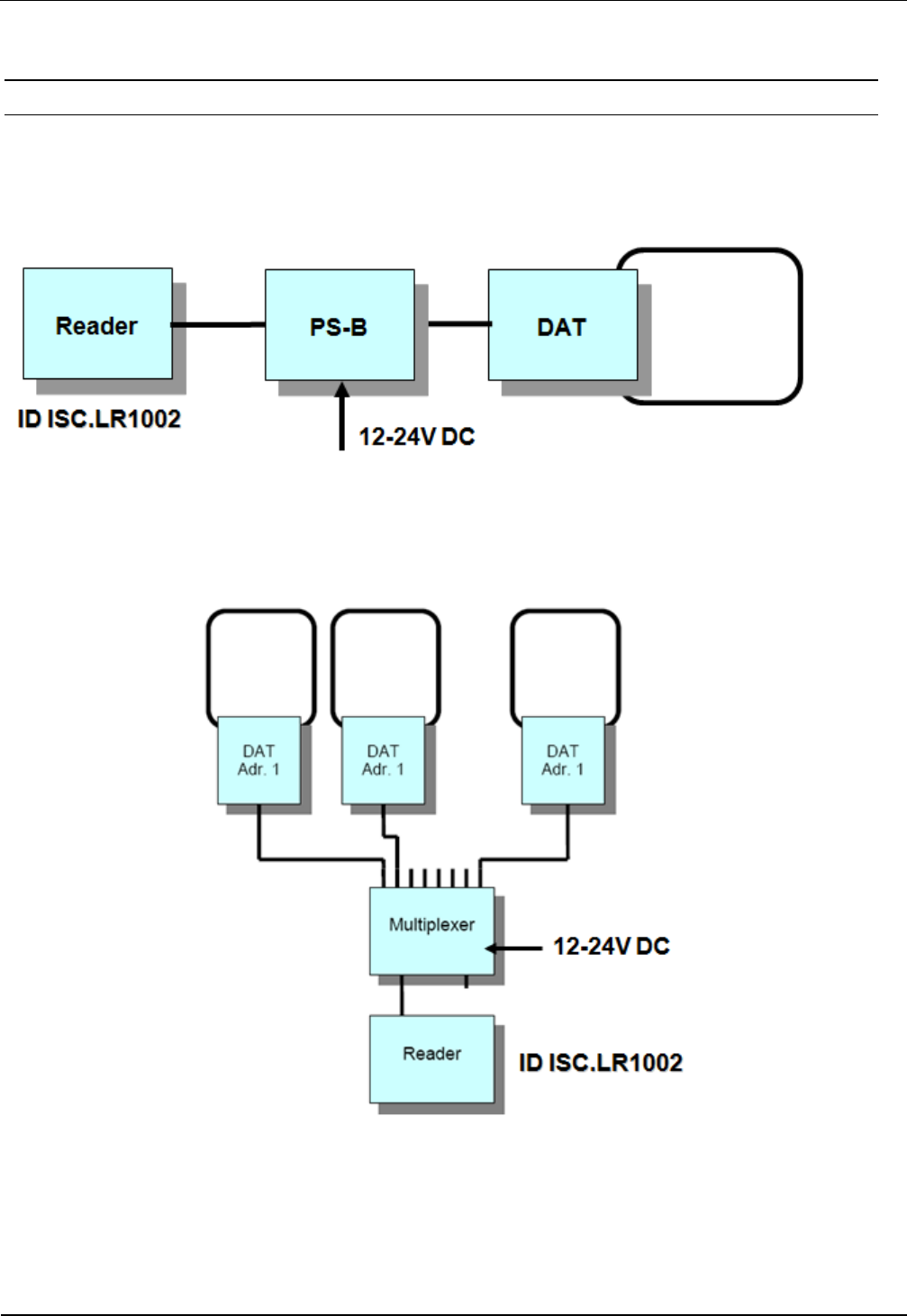
3.2.1.1 Connection of a ID ISC.DAT (Dynamic Antenna Tuning Board)
For tuning a ID ISC.DAT tuning board a DC voltage is required. This DC voltage must be provided
via a power splitter (ID ISC.ANT.PS-B) or a antenna multiplexer (ID ISC.ANT.MUX)
Figure 4 shows the DC supply of the ID ISC.DAT with a power splitter.
Figure 4: DC supply of a ID ISC.DAT using a power splitter ID ISC.ANT-PS-B
Figure 5 shows the DC supply of the ID ISC.DAT with a Antenna Multiplexer.
Figure 5: DC supply of a ID ISC.DAT using a ID ISC.ANT.MUX.
OBID i-scan® HF Integration Manual ID ISC.LRM1002-E
FEIG ELECTRONIC GmbH Page 10 from 24 M21110-0e-ID-B-P.docx
3.2.2 Supply voltage
The supply voltage of 24 V is connected to Terminal X1.
Terminal Abbreviation Description
X1 VIN Vcc – supply voltage + 24 V
X1 GND Ground – supply voltage
Table 3: Pin-outs for supply voltage on X1
GND
V
IN
X1 X5
Figure 6: Position oft he connector X1 for the power supply
Note:
• Reversing the supply voltage polarity may destroy the device.
• For reducing the noise the power supply line can be fitted with one EMC ring cores ∅ 28
mm x 20 mm. The power supply line must be wound around the ring core for at least 5
turns. The distance between the Reader termination and the ring core should be maxi-
mum 10 cm.

OBID i-scan® HF Integration Manual ID ISC.LRM1002-E
FEIG ELECTRONIC GmbH Page 11 from 24 M21110-0e-ID-B-P.docx
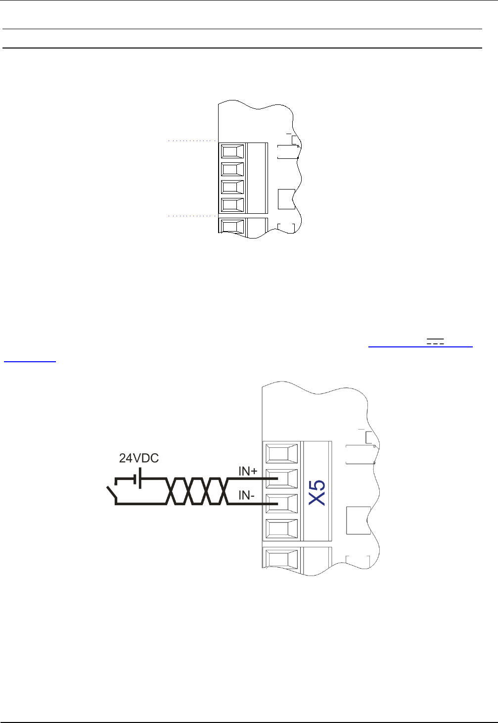
3.2.3 OptocouplerInputs (X5 / IN1)
The optocoupler input is available on Terminal X5.
GND
V
IN
IN -
IN +
X5
Figure 7: Optocoupler pin-outs on terminal X5
The optocoupler on terminal strips X5 is galvanically isolated from the Reader electronics and
must therefore be powered externally. The external VCC voltage and GND (Ground) may however
be provided by the connector VIN (24VDC) and GND from the reader. See: Output 24V (X5 /
VIN, GND)
Figure 8: External power supply for the optocouplers

OBID i-scan® HF Integration Manual ID ISC.LRM1002-E
FEIG ELECTRONIC GmbH Page 12 from 24 M21110-0e-ID-B-P.docx
Figure 9: Possible internal power supply for the optocouplers
The input LED for the optocoupler is internally connected to a series resistor of 3,74kΩ and is
limited to an input current of max. 6mA.
Note:
• The input is configured for a maximum input voltage of 24 V and an input current
of maximum 6mA.
• Reversing the polarity or overloading the input can destroy the device.
• Using internal and external voltage at the same time can destroy the reader.
OBID i-scan® HF Integration Manual ID ISC.LRM1002-E
FEIG ELECTRONIC GmbH Page 13 from 24 M21110-0e-ID-B-P.docx
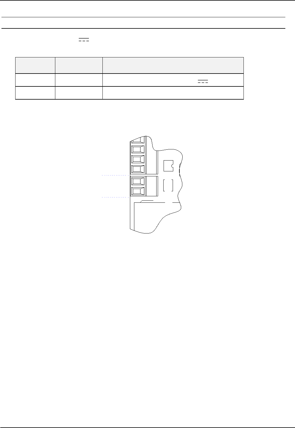
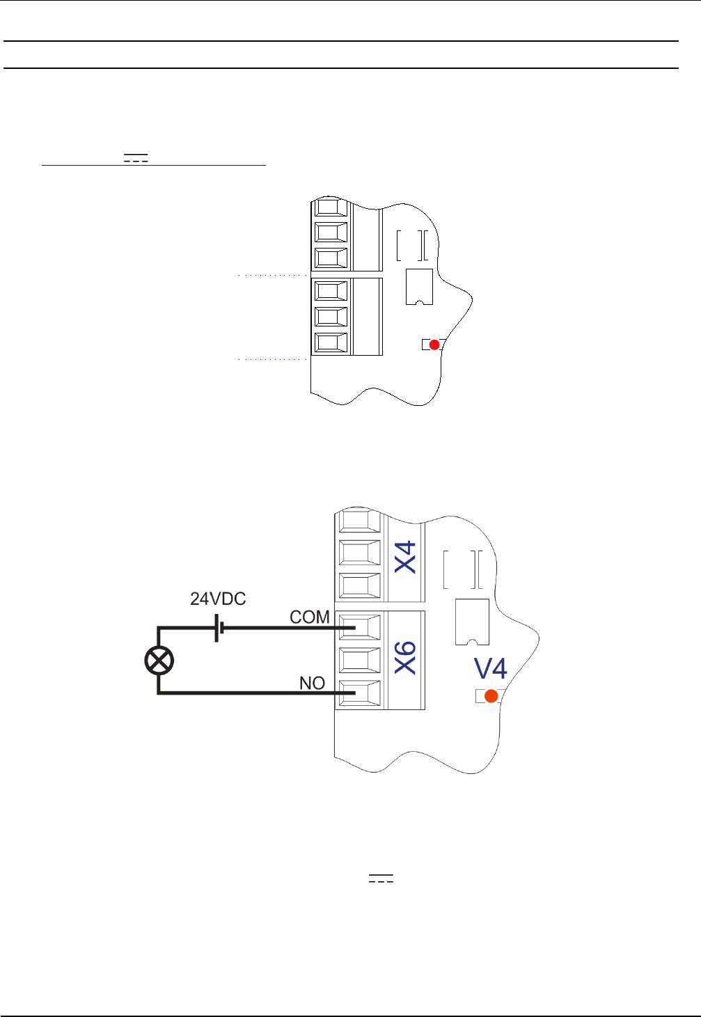
3.3 Relay (X6 / REL1)
The relay output has a changeover contact. These outputs, which are located on terminals X6, is
galvanically isolated from the Reader electronics and must therefore be externally supplied. The
external voltage may however be provided by the reader from connector X5 VIN and GND.
See: Output 24V (X5 / VIN, GND)
V4
NO
NC
COM
X4
X6
Figure 10: Relay Outputs on terminal X6
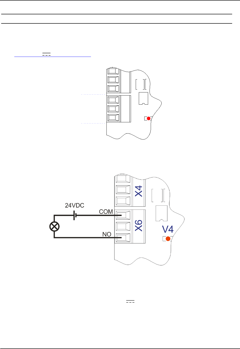
Figure 11: External wiring of the relay output’s with external voltage
Notes:
• The relay output is configured for max. 24 V / 1 A.
• The relay output is intended for switching resistive loads only. If an inductive load is
connected, the relay contacts must be protected by means of an external protection
circuit.
• Using internal and external voltage at the same time can destroy the reader.
OBID i-scan® HF Integration Manual ID ISC.LRM1002-E
FEIG ELECTRONIC GmbH Page 14 from 24 M21110-0e-ID-B-P.docx
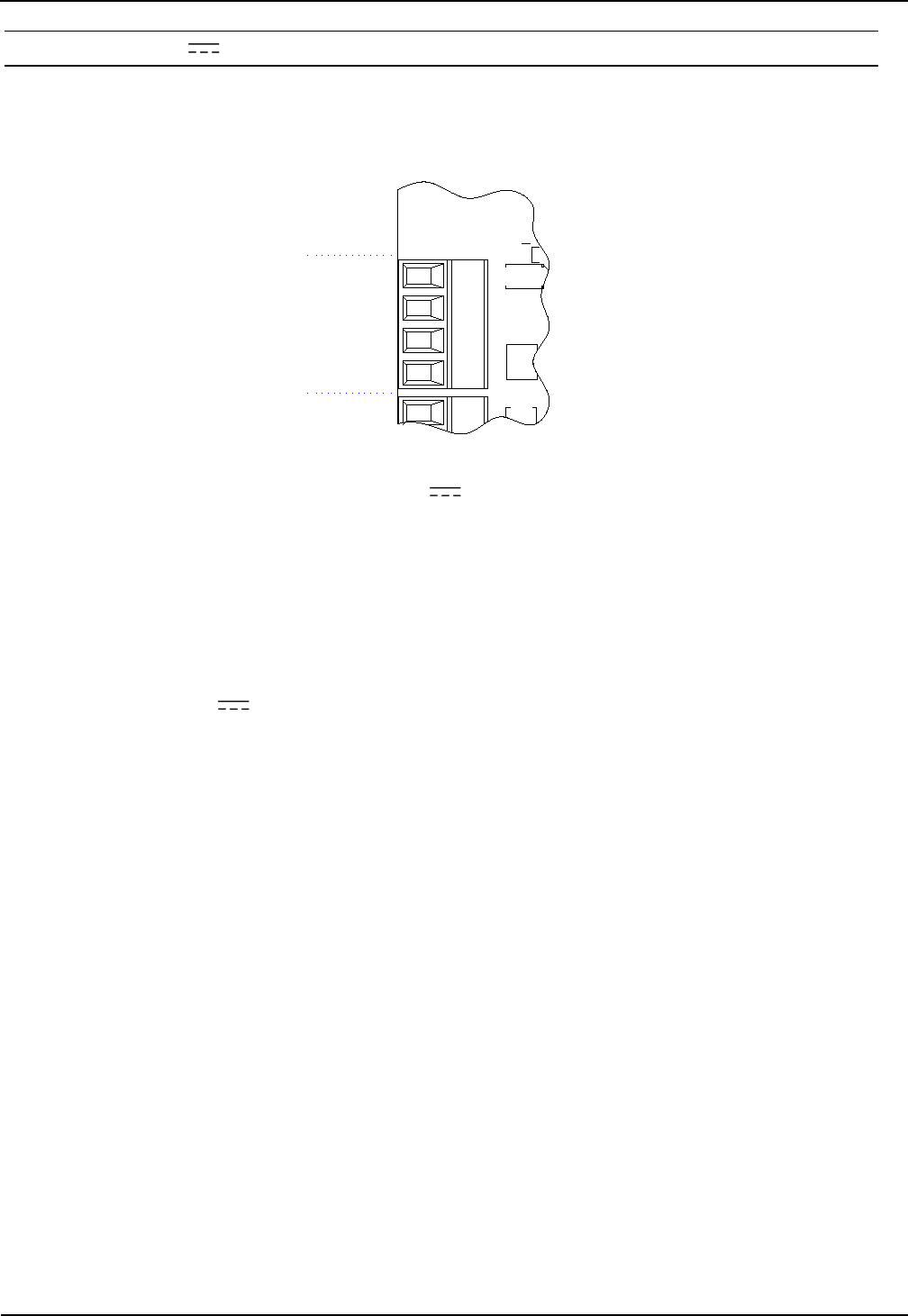
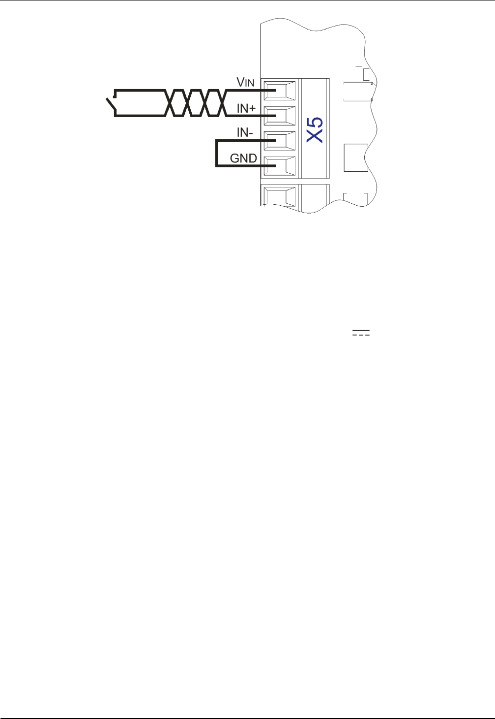
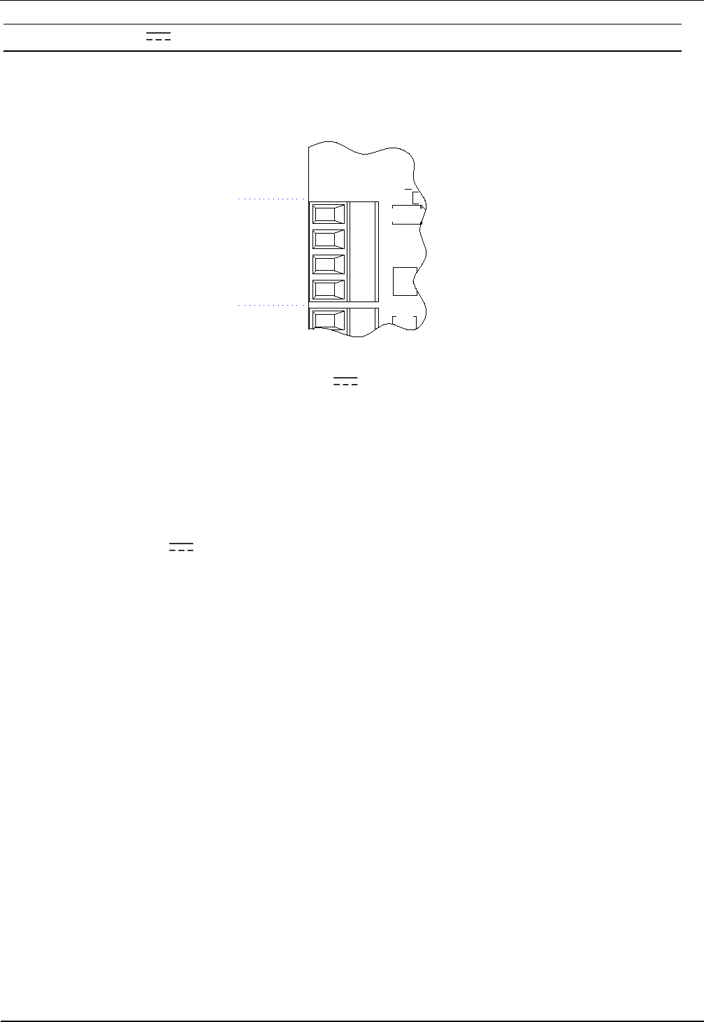
3.3.1 Output 24V (X5 / VIN, GND)
The output VIN/GND can be used to power the optional external circuitry of the digital inputs or
relay. The maximum current consumption must not exceed 1A.
GND
VIN
IN -
IN +
X5
Figure 12: Optional 24V external voltage supply
Note:
• For the dimensioning oft the power supply the power consumption for the external
output circuitry must be additional considered to the typical reader power consump-
tion.
• The internal 24V voltage on X5 is not protected by a fuse.
OBID i-scan® HF Integration Manual ID ISC.LRM1002-E
FEIG ELECTRONIC GmbH Page 15 from 24 M21110-0e-ID-B-P.docx
3.4 Interfaces
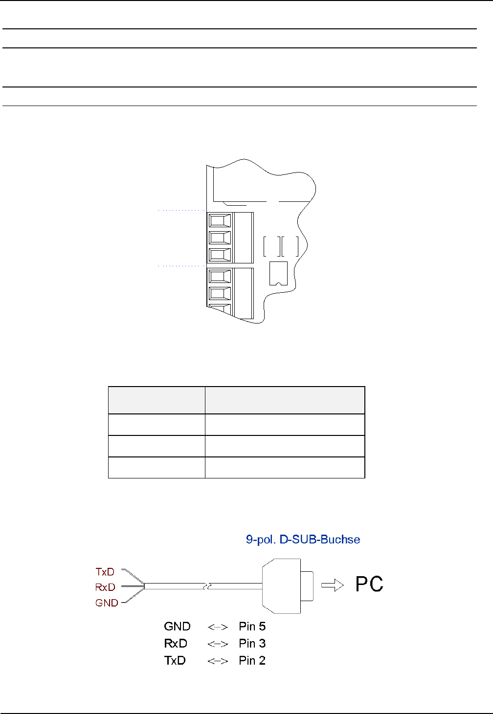
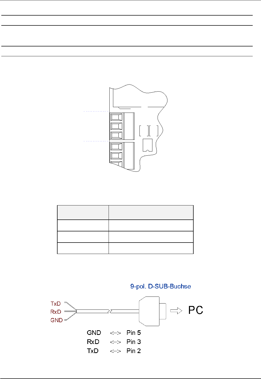
3.4.1 RS232-Interface X4
The RS232 interface is connected on X4. The transmission parameters can be configured by
means of software protocol.
TxD
RxD
GND
X4
X6
Figure 13: RS232 interface pin-outs on X4
Kurzzeichen Description
TxD RS232 – (Transmit)
RxD RS232 – (Receive)
GND RS232 – (Ground)
Table 4: Pin assignment of the RS232-Interface
Figure 14: Wiring example for connecting the RS232 interface
OBID i-scan® HF Integration Manual ID ISC.LRM1002-E
FEIG ELECTRONIC GmbH Page 16 from 24 M21110-0e-ID-B-P.docx
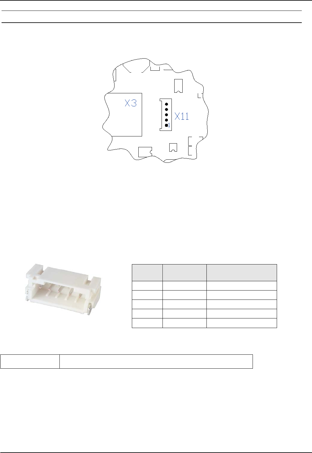
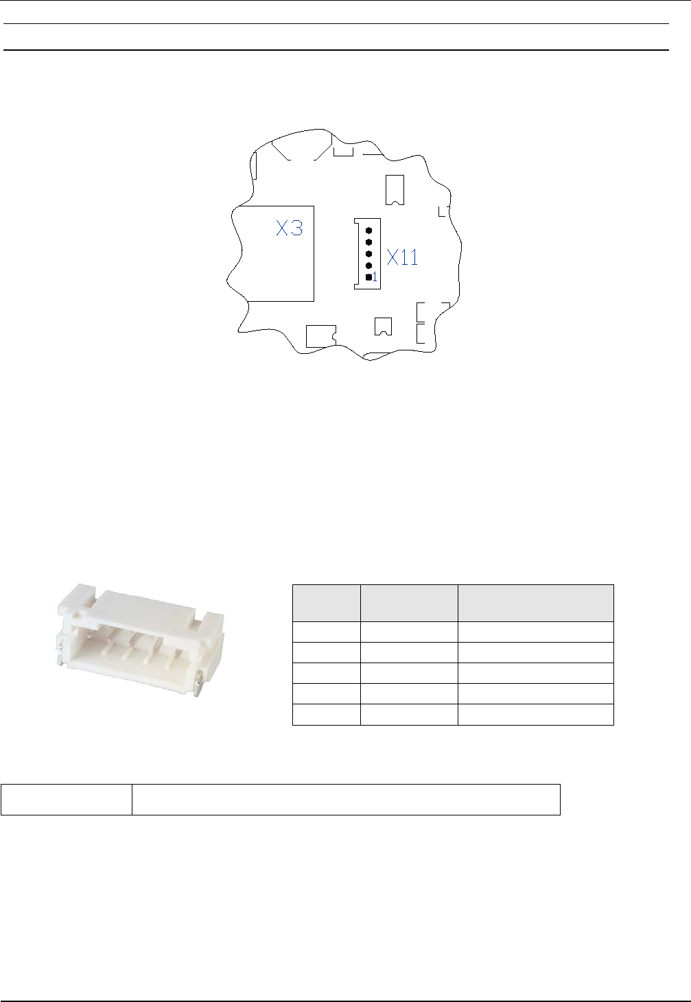
3.4.2 USB – Interface X11 (Host Communication)
The USB socket on the board is terminal X11. The data rate is reduced to 12 Mbit (USB full
speed). A standard USB-cable can be used.
The Figure 19 and table shows the connection of connector X11 (5pol.) type “JST PH” RM 2 mm
(vertical).
X2
Pin-No.
1 Shielding USB cable - shielding
2 GND
3 USB-D PLUS
4 USB-D MINUS
5 VCC + 5 V DC ± 5 %
Optional the following USB cable can be ordered:
3541.000.00 ID CAB.USB-B Cable for Interface USB/JST PH
Note:
The length of the USB-cable can be a max. of 5m (200 inch). It is not allowed to use longer
cables.
Figure 15: USB-Interface for host communication
Figure
16: Connector „JST PH“
OBID i-scan® HF Integration Manual ID ISC.LRM1002-E
FEIG ELECTRONIC GmbH Page 17 from 24 M21110-0e-ID-B-P.docx
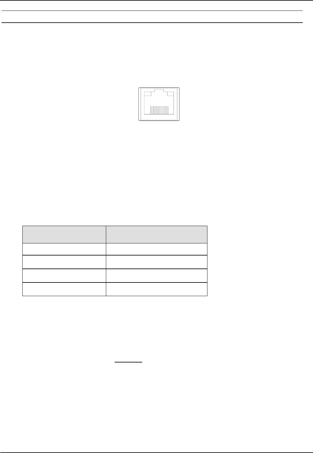
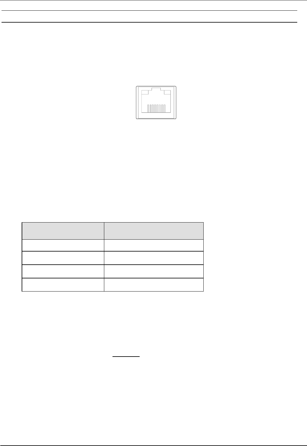
3.4.3 Ethernet-Interface on X3 (10/100 Base-T)
The Reader has an integrated 10 / 100 Base-T network port for an RJ-45. Connection is made on
X3 and has an automatic “Crossover Detection” according to the 1000 Base-T Standard.
With structured cabling CAT 5 cables should be used. This ensures a reliable operation at 10 Mbps
or 100 Mbps.
The prerequisite for using TCP/IP protocol is that each device has a unique address on the net-
work. All Readers have a factory set IP address.
Network Address
IP-Adresse 192.168.10.10
Subnet-Mask 255.255.255.0
Port 10001
DHCP OFF
Table 5 Standard factory configuration of the Ethernet connection
Note:
• The Reader TCP/IP interface has a DHCP option.
• It is recommended to use a shielded twisted pair STP CAT5 cable.
X3
Figure 17: LAN interface for host communication

OBID i-scan® HF Integration Manual ID ISC.LRM1002-E
FEIG ELECTRONIC GmbH Page 18 from 24 M21110-0e-ID-B-P.docx
4 Operating and Display Elements
4.1 LEDs
Table 6 shows the LED configuration.
Abbreviation Description
LED V1 (green) "RUN-LED 1"
- Indicates proper running of the internal Reader software (DSP)
- Comes on during Reader initialization after power-on or after a
reset.
LED V2 (blue) Diagnostic 1: RF communication / EEPROM status
- Short flashing indicates errorless communication with a
transponder on the RF interface
- Flashes alternately with V1 after a reset following a software
update
- Flashes alternately with V1 in case of a data error when
reading the parameters after a reset
LED V3 (yellow) Diagnostic 2: Host communication
- Short flashing indicates sending of a protocol to the host on the
RS232/USB and LAN-Interface
LED V5 (red) Diagnostic 4: RF warning
- Comes on when there is an error in the RF section of the
Reader. The error type can be read out via software over the
RS232/USB and LAN-Interface
Table 6: LED configuration

OBID i-scan® HF Integration Manual ID ISC.LRM1002-E
FEIG ELECTRONIC GmbH Page 19 from 24 M21110-0e-ID-B-P.docx
5 Radio Approvals
5.1 Europe (CE)
When used according to regulation, this radio equipment conforms with the basic requirements of
Article 3 and the other relevant provisions of the R&TTE Guideline 1999/E6 dated March 99.
Equipment Classification according ETSI EN 301 489: Class 2 SRD

OBID i-scan® HF Integration Manual ID ISC.LRM1002-E
FEIG ELECTRONIC GmbH Page 20 from 24 M21110-0e-ID-B-P.docx
5.2 USA (FCC) and Canada (IC)
5.2.1 USA (FCC) and Canada (IC) warning notices
Product name:
ID ISC.LRM1002-E
Reader name:
ID ISC.LRM1002-E
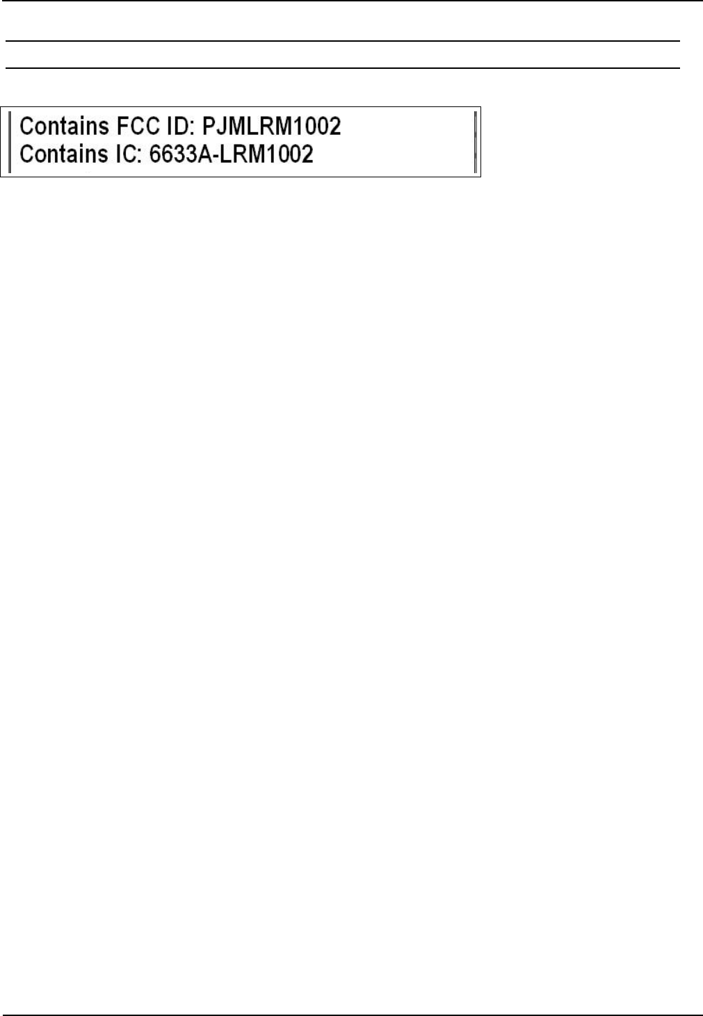
FCC ID:
IC:
PJMLRM1002
6633A-LRM1002
Notice for USA and
Canada
This device complies with Part 15 of the FCC Rules and with
RSS-210 of Industry Canada.
Operation is subject to the following two conditions.
(1) this device may not cause harmful interference, and
(2) this device must accept any interference received,
including interference that may cause undesired operation.
Unauthorized modifications may void the authority granted under
Federal communications Commission Rules permitting the operation
of this device.
This equipment has been tested and found to comply with the limits for
a Class A digital device, pursuant to Part 15 of the FCC Rules. These
limits are designed to provide reasonable protection against harmful
interference when the equipment is operated in a commercial
environment. This equipment generates, uses, and can radiate radio
frequency energy and, if not installed and used in accordance with the
instruction manual, may cause harmful interference to radio
communications. Operation of this equipment in a residential area is
likely to cause harmful interference in which case the user will be
required to correct the interference at his own expense.
Le présent appareil est conforme aux CNR d'Industrie Canada appli-
cables aux appareils radio exempts de licence. L'exploitation est auto-
risée aux deux conditions suivantes :
(1) l'appareil ne doit pas produire de brouillage, et
(2) l'utilisateur de l'appareil doit accepter tout brouillage radioélectrique
subi, même si le brouillage est susceptible d'en compromettre le fonc-
tionnement.
Warning: Changes or modification made to this equipment not expressly approved by
FEIG ELECTRONIC GmbH may void the FCC authorization to operate this equipment.
OBID i-scan® HF Integration Manual ID ISC.LRM1002-E
FEIG ELECTRONIC GmbH Page 21 from 24 M21110-0e-ID-B-P.docx
5.3 Label Information Reader Modul ID ISC.LRM1002-E
The following information has to be mount outside on the housing of the reader.

OBID i-scan® HF Integration Manual ID ISC.LRM1002-E
FEIG ELECTRONIC GmbH Page 22 from 24 M21110-0e-ID-B-P.docx
5.3.1 USA (FCC) and Canada (IC) approved antennas
This radio transmitter (identify the device by certification number, or model number if Category II)
has been approved by Industry Canada to operate with the antenna types listed below with maxi-
mum permission gain and required antenna impedance for each antenna type indicated. Antenna
types not included in this list. Having a gain greater than the maximum gain indicated for that type,
are strictly prohibited for use with this device
Following antennas are approved by FCC according FCC Part 15 and IC Canada according
RS210
• ID ISC.ANT310/310-A
• ID ISC.ANTS370/270-A
• ID ISC.ANT1300/680-A

OBID i-scan® HF Integration Manual ID ISC.LRM1002-E
FEIG ELECTRONIC GmbH Page 23 from 24 M21110-0e-ID-B-P.docx
6 Technical Data
Mechanical Data
• Dimensions ( W x H x D ) 160 x 120 x 35 mm³
6,29 x 4,72 x 1,37 inch³
• Weight Approx. 0,35 kg
0,77 lb
Electrical Data
• Supply Voltage 24 V ± 15 %
Noise Ripple : max. 150 mV
• Power Consumption max. 16 VA
• Operating Frequency 13,56 MHz
• Transmit Power 1W – 5 W
• Modulation 14%
• Antenna Connection SMA Jack (50 Ω, SWR≤1.3)
• DC Supply at Antenna Con-
nector
6,5 V (max. 20mA)
• Diagnostic Options internal impedance monitoring
internal temperature monitoring
• Outputs
– 1 Relay (NO)
24 V / 1 A
• Inputs
– 1 Optocoupler
24 V / 6 mA
• Interfaces - RS232
- USB
- Ethernet (TCP/IP)
• Protocol Modes - FEIG ISO HOST
- BRM (Data Filtering and Data Buffering
- Scan Mode
- Notification Mode

OBID i-scan® HF Integration Manual ID ISC.LRM1002-E
FEIG ELECTRONIC GmbH Page 24 from 24 M21110-0e-ID-B-P.docx
• Supported Transponders • ISO15693, ISO18000-3 MODE 1
(EM HF ISO Chips, Fujitsu HF ISO Chips,
KSW Sensor Chips, IDS Sensor Chips,
Infineon my-d, NXP I-Code, STM ISO Chips,
TI Tag-it)
• Optical Indicators 4 LEDs for Operating Status Diagnostics
Ambient
• Temperature Range
– Operating
– Storage
-20°C to +55°C (-4°F to +131°F)
-25°C to +85°C (-13°F to +185°F)
• Humidity 5% - 80%, no condensation
• Vibration EN 60068-2-6
10 Hz to 150 Hz : 0,075 mm / 1 g
• Shock EN 60068-2-27
Acceleration : 30 g
Applicable Standards
• RF Approval
– Europe
– USA
EN 300 330
FCC 47 CFR Part 15
• EMC EN 301 489
• Safety
– Low Voltage Directive
– Human Exposure
EN 60950
EN 50364
INSTALLATION
final – public (B)
2012-11-13 – M20413-3e-ID-B.docx
ID ISC.LR1002-E
Long Range Reader
(English)

OBID
i-scan
®
HF
Installation
ID ISC.LR1002-E
FEIG ELECTRONIC GmbH Page 2 from 23 M20413-3e-ID-B.docx
Note
Copyright 2012 by
FEIG ELECTRONIC GmbH
Lange Strasse 4
D-35781 Weilburg-Waldhausen
Tel.: +49 6471 3109-0
http://www.feig.de
With the edition of this document, all previous editions become void. Indications made in this manual may be
changed without previous notice.
Copying of this document, and giving it to others and the use or communication of the contents thereof are
forbidden without express authority. Offenders are liable to the payment of damages. All rights are reserved
in the event of the grant of a patent or the registration of a utility model or design.
Composition of the information in this document has been done to the best of our knowledge. FEIG
ELECTRONIC GmbH does not guarantee the correctness and completeness of the details given in this
manual and may not be held liable for damages ensuing from incorrect or incomplete information. Since,
despite all our efforts, errors may not be completely avoided, we are always grateful for your useful tips.
The instructions given in this manual are based on advantageous boundary conditions. FEIG ELECTRONIC
GmbH does not give any guarantee promise for perfect function in cross environments.
FEIG call explicit attention that devices which are subject of this document are not designed with compo-
nents and testing methods for a level of reliability suitable for use in or in connection with surgical implants or
as critical components in any life support systems whose failure to perform can reasonably be expected to
cause significant injury to a human. To avoid damage, injury, or death, the user or application designer must
take reasonably prudent steps to protect against system failures.
FEIG ELECTRONIC GmbH assumes no responsibility for the use of any information contained in this docu-
ment and makes no representation that they free of patent infringement. FEIG ELECTRONIC GmbH does
not convey any license under its patent rights nor the rights of others.
OBID® and OBID i-scan® are registered trademarks of FEIG ELECTRONIC GmbH.

OBID
i-scan
®
HF
Installation
ID ISC.LR1002-E
FEIG ELECTRONIC GmbH Page 3 from 23 M20413-3e-ID-B.docx
Content
1 Safety Instructions / Warning - Read before start-up ! 4
2 Performance Features of Reader Family ID ISC.LR1002 5
2.1 Performance Features ................................................................................................ 5
2.2 Available Reader Types .............................................................................................. 5
3 Installation and mounting 6
3.1 Mounting ID ISC.LR1002-E (Housing)........................................................................ 6
3.1.1 Seal caps ................................................................................................................. 7
3.1.2 Cover stays .............................................................................................................. 7
3.1.3 Decorative covers .................................................................................................... 7
3.2 Terminals ..................................................................................................................... 8
3.2.1 Antenna connection ................................................................................................. 9
3.2.1.1 Connection of a ID ISC.DAT (Dynamic Antenna Tuning Board) ................... 10
3.2.2 Supply voltage........................................................................................................ 11
3.2.3 OptocouplerInputs (X5 / IN1) .................................................................................. 12
3.3 Relay (X6 / REL1) ...................................................................................................... 14
3.3.1 Output 24V (X5 / VIN, GND) ........................................................................... 15
3.4 Interfaces ................................................................................................................... 16
3.4.1 RS232-Interface X4 ................................................................................................ 16
3.4.2 USB – Interface X11 (Host Communication) .......................................................... 17
3.4.3 Ethernet-Interface on X3 (10/100 Base-T) .............................................................. 18
4 Operating and Display Elements 19
4.1 LEDs .......................................................................................................................... 19
5 Radio Approvals 20
5.1 Europe (CE) ............................................................................................................... 20
5.2 USA (FCC) and Canada (IC) ..................................................................................... 21
6 Technical Data 22

OBID
i-scan
®
HF
Installation
ID ISC.LR1002-E
FEIG ELECTRONIC GmbH Page 4 from 23 M20413-3e-ID-B.docx
1 Safety Instructions / Warning - Read before start-up !
• The device may only be used for the purpose intended by the manufacturer.
• The operation manual should be kept readily available at all times for each user.
• Unauthorized changes and the use of spare parts and additional devices which have not been
sold or recommended by the manufacturer may cause fire, electric shocks or injuries. Such
unauthorized measures shall exclude the manufacturer from any liability.
• The liability-prescriptions of the manufacturer in the issue valid at the time of purchase are valid
for the device. The manufacturer shall not be held legally responsible for inaccuracies, errors,
or omissions in the manual or automatically set parameters for a device or for an incorrect
application of a device.
• Repairs may only be undertaken by the manufacturer.
• Installation, operation, and maintenance procedures should only be carried out by qualified
personnel.
• Use of the device and its installation must be in accordance with national legal requirements
and local electrical codes .
• When working on devices the valid safety regulations must be observed.
• Before touching the device, the power supply must always be interrupted. Make sure that the
device is without voltage by measuring. The fading of an operation control (LED) is no indicator
for an interrupted power supply or the device being out of voltage!
• Special advice for wearers of cardiac pacemakers:
Although this device doesn't exceed the valid limits for electromagnetic fields you should keep
a minimum distance of 25 cm between the device and your cardiac pacemaker and not stay in
the immediate proximity of the device’s antenna for any length of time.

OBID
i-scan
®
HF
Installation
ID ISC.LR1002-E
FEIG ELECTRONIC GmbH Page 5 from 23 M20413-3e-ID-B.docx
2 Performance Features of Reader ID ISC.LR1002
2.1 Performance Features
The Reader has been developed for reading passive data carriers, so-called „Smart Labels“, using
an operating frequency of 13.56 MHz. For the operation it is necessary to connect a appropriate
external antenna to the connector ANT1.
2.2 Available Reader Types
The following Reader type’s are currently available:
Reader type Description
ID ISC.LR1002-E Housing version with RS232 / USB / LAN-Interface
Table 1: Available Reader types
OBID
i-scan
®
HF
Installation
ID ISC.LR1002-E
FEIG ELECTRONIC GmbH Page 6 from 23 M20413-3e-ID-B.docx
3 Installation and mounting
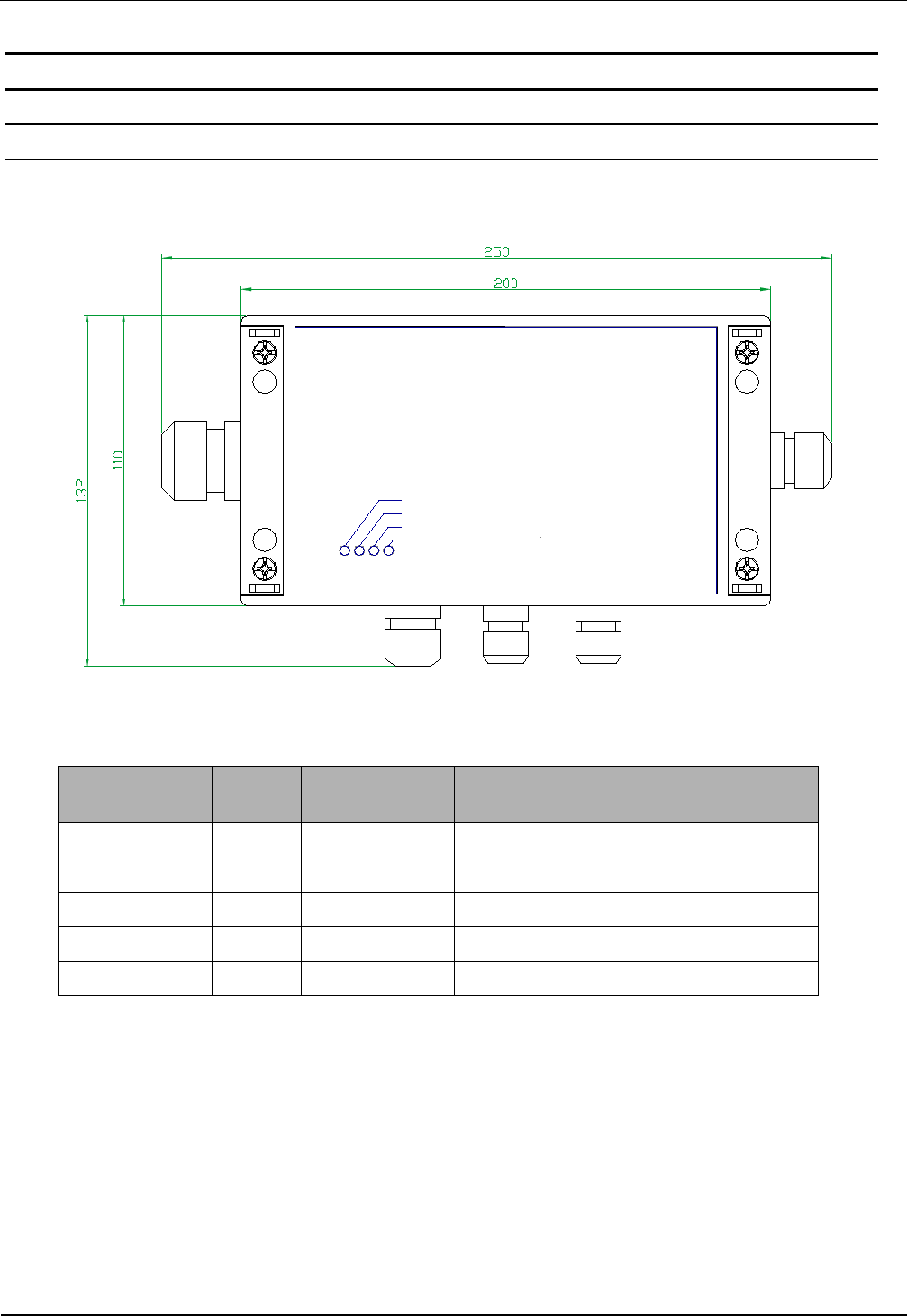
3.1 Mounting ID ISC.LR1002-E (Housing)
The Reader is designed for wall mount, including outdoors. Holes are provided in the housing for
wall attachment. The housing does not need to be opened for installation on a wall (see Figure 2).
USB / LAN
HF
Input / Output
Run
Host
Diag.
Antenna
Com Power
Figure 1: Housing ID ISC.LR1002-E (all dimensions in mm)
Cable gland Size Clamping range
[mm] Description
1 M 16 4,5 – 10 Antenna cable
2 M 12 3,5 – 7 Supply voltage
3 M 12 3,5 – 7 Interface (serial/USB)
2 M 16 4,5 – 10 Digital Input / Relais Output
6 M 25 9 – 17 Ethernet Interface
Table 2: Cable glands ID ISC.LR1002-E
OBID
i-scan
®
HF
Installation
ID ISC.LR1002-E
FEIG ELECTRONIC GmbH Page 7 from 23 M20413-3e-ID-B.docx
3.1.1 Seal caps
The seal caps included in the scope of delivery can be used to close off unused cable fittings. Only
than the protection class IP54 can be reached.
The reducing ring provided is intended for the network connection. The slotted reducer is placed
over the network cable and then fixed in place in the cable gland.
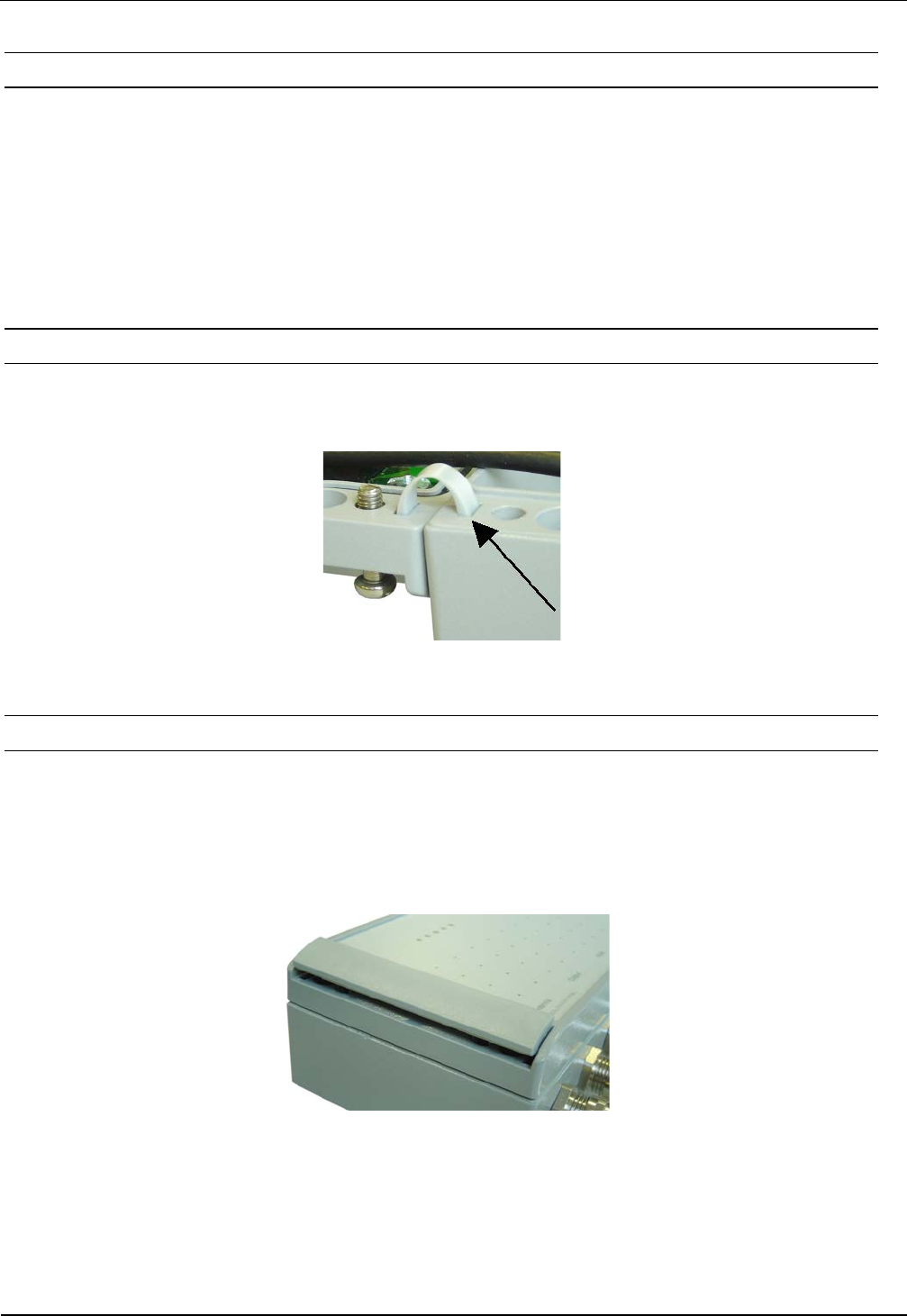
3.1.2 Cover stays
The two cover stays can be used to attach the cover to the housing. The cover stays are inserted
into the openings provided for this purpose.
Figure 2: Cover stay
3.1.3 Decorative covers
The decorative covers are attached after installing the Reader.
The slot on the long side of the cover is used for disassembling the cover. Use a screwdriver to
remove the cover.
Figure 3: Decorative cover
OBID
i-scan
®
HF
Installation
ID ISC.LR1002-E
FEIG ELECTRONIC GmbH Page 9 from 23 M20413-3e-ID-B.docx
3.2.1 Antenna connection
The SMA socket „ANT1“ is located on the circuit board for connecting the antenna to the ID
ISC.LR1002.
A external LED can also be supplied with 6,5 V through the antenna terminal.
This can be controlled by software. The maximum current draw is then not allowed to exceed
20mA.
The voltage is not sufficient to support the dynamic antenna tuning board ID ISC.DAT
See: Connection of a ID ISC.DAT (Dynamic Antenna Tuning Board)
The maximum tightening torque for the SMA socket is 0.45 Nm (4.0 lbf in).
Attention:
Exceeding the tightening torque will destroy the socket.
Terminal Description
ANT1 For connecting the antenna
(Input Impedance 50Ω)
Table 3: Antenna jack
• The standing wave ratio VSWR for the antenna should not exceed a value of 1,3.
• For reaching optimal read ranges the coaxial cables between readers and antenna must
have defined lengths. For all antennas of the company FEIG ELECTRONICS GmbH and
for all antennas which with the tuning boards (e.g. ID ISC.DAT, ID ISC.MAT b and ID
ISC.MAT s) of FEIG ELECTRONICS GmbH is made the optimal length of the coaxial ca-
ble is 1.35 m (Article No. 1654.004.00.00, Name ID ISC.ANT.C-B). See also Mounting
Manual Power Splitter ID ISC.ANT.PS-B and ID ISC.ANT.MUX.
• The optimum operating Q factor of the antenna should be in a range of Qoper = 10...30. To
determine the operating Q the antenna must be supplied with a 50 Ohm source such as
a network analyzer or frequency generator.
• To prevent external coupled noise, the antenna cable must be fitted with the included
EMC ferrite ring core ∅ 28 mm x 20 mm. The antenna line must be wound around the
ring core for at least 4 turns. The distance between the Reader termination and the ring
core should be maximum 10 cm (see Figure 6).
• When connecting an antenna, ensure that it does not exceed the permissible limits pre-
scribed by the national regulations for radio frequency devices.
Figure 5: Antenna line with EMC ring cores
OBID
i-scan
®
HF
Installation
ID ISC.LR1002-E
FEIG ELECTRONIC GmbH Page 10 from 23 M20413-3e-ID-B.docx
3.2.1.1 Connection of a ID ISC.DAT (Dynamic Antenna Tuning Board)
For tuning a ID ISC.DAT tuning board a DC voltage is required. This DC voltage must be provided
via a power splitter (ID ISC.ANT.PS-B) or a antenna multiplexer (ID ISC.ANT.MUX)
Figure 7 shows the DC supply of the ID ISC.DAT with a power splitter.
Figure 6: DC supply of a ID ISC.DAT using a power splitter ID ISC.ANT-PS-B
Figure 8 shows the DC supply of the ID ISC.DAT with a Antenna Multiplexer.
Figure 7: DC supply of a ID ISC.DAT using a ID ISC.ANT.MUX.

OBID
i-scan
®
HF
Installation
ID ISC.LR1002-E
FEIG ELECTRONIC GmbH Page 11 from 23 M20413-3e-ID-B.docx
3.2.2 Supply voltage
The supply voltage of 24 V is connected to Terminal X1.
Terminal Abbreviation Description
X1 VIN Vcc – supply voltage + 24 V
X1 GND Ground – supply voltage
Table 4: Pin-outs for supply voltage on X1
GND
V
IN
X1 X5
Figure 8: Position oft he connector X1 for the power supply
Note:
• Reversing the supply voltage polarity may destroy the device.
• For reducing the noise the power supply line can be fitted with one EMC ring cores ∅ 28
mm x 20 mm. The power supply line must be wound around the ring core for at least 5
turns. The distance between the Reader termination and the ring core should be maxi-
mum 10 cm.
OBID
i-scan
®
HF
Installation
ID ISC.LR1002-E
FEIG ELECTRONIC GmbH Page 12 from 23 M20413-3e-ID-B.docx
3.2.3 OptocouplerInputs (X5 / IN1)
The optocoupler input is available on Terminal X5.
GND
VIN
IN -
IN +
X5
Figure 9: Optocoupler pin-outs on terminal X5
The optocoupler on terminal strips X5 is galvanically isolated from the Reader electronics and
must therefore be powered externally. The external VCC voltage and GND (Ground) may however
be provided by the connector VIN (24VDC) and GND from the reader. See: Output 24V (X5 /
VIN, GND)
Figure 10: External power supply for the optocouplers
OBID
i-scan
®
HF
Installation
ID ISC.LR1002-E
FEIG ELECTRONIC GmbH Page 13 from 23 M20413-3e-ID-B.docx
Figure 11: Possible internal power supply for the optocouplers
The input LED for the optocoupler is internally connected to a series resistor of 3,74kΩ and is
limited to an input current of max. 6mA.
Note:
• The input is configured for a maximum input voltage of 24 V and an input current
of maximum 6mA.
• Reversing the polarity or overloading the input can destroy the device.
• Using internal and external voltage at the same time can destroy the reader.
OBID
i-scan
®
HF
Installation
ID ISC.LR1002-E
FEIG ELECTRONIC GmbH Page 14 from 23 M20413-3e-ID-B.docx
3.3 Relay (X6 / REL1)
The relay output has a changeover contact. These outputs, which are located on terminals X6, is
galvanically isolated from the Reader electronics and must therefore be externally supplied. The
external voltage may however be provided by the reader from connector X5 VIN and GND.
See: Output 24V (X5 / VIN, GND)
V4
NO
NC
COM
X4
X6
Figure 12: Relay Outputs on terminal X6
Figure 13: External wiring of the relay output’s with external voltage
Notes:
• The relay output is configured for max. 24 V / 1 A.
• The relay output is intended for switching resistive loads only. If an inductive load is
connected, the relay contacts must be protected by means of an external protection
circuit.
• Using internal and external voltage at the same time can destroy the reader.
OBID
i-scan
®
HF
Installation
ID ISC.LR1002-E
FEIG ELECTRONIC GmbH Page 15 from 23 M20413-3e-ID-B.docx
3.3.1 Output 24V (X5 / VIN, GND)
The output VIN/GND can be used to power the optional external circuitry of the digital inputs or
relay. The maximum current consumption must not exceed 1A.
GND
VIN
IN -
IN +
X5
Figure 14: Optional 24V external voltage supply
Note:
• For the dimensioning oft the power supply the power consumption for the external
output circuitry must be additional considered to the typical reader power consump-
tion.
• The internal 24V voltage on X5 is not protected by a fuse.
OBID
i-scan
®
HF
Installation
ID ISC.LR1002-E
FEIG ELECTRONIC GmbH Page 16 from 23 M20413-3e-ID-B.docx
3.4 Interfaces
3.4.1 RS232-Interface X4
The RS232 interface is connected on X4. The transmission parameters can be configured by
means of software protocol.
TxD
RxD
GND
X4
X6
Figure 15: RS232 interface pin-outs on X4
Kurzzeichen Description
TxD RS232 – (Transmit)
RxD RS232 – (Receive)
GND RS232 – (Ground)
Table 5: Pin assignment of the RS232-Interface
Figure 16: Wiring example for connecting the RS232 interface
OBID
i-scan
®
HF
Installation
ID ISC.LR1002-E
FEIG ELECTRONIC GmbH Page 17 from 23 M20413-3e-ID-B.docx
3.4.2 USB – Interface X11 (Host Communication)
The USB socket on the board is terminal X11. The data rate is reduced to 12 Mbit (USB full
speed). A standard USB-cable can be used.
The Figure 19 and table shows the connection of connector X11 (5pol.) type “JST PH” RM 2 mm
(vertical).
X2
Pin-No.
1 Shielding USB cable - shielding
2 GND
3 USB-D PLUS
4 USB-D MINUS
5 VCC + 5 V DC ± 5 %
Optional the following USB cable can be ordered:
3541.000.00 ID CAB.USB-B Cable for Interface USB/JST PH
Note:
The length of the USB-cable can be a max. of 5m (200 inch). It is not allowed to use longer
cables.
Figure 17: USB-Interface for host communication
Figure
18: Connector „JST PH“
OBID
i-scan
®
HF
Installation
ID ISC.LR1002-E
FEIG ELECTRONIC GmbH Page 18 from 23 M20413-3e-ID-B.docx
3.4.3 Ethernet-Interface on X3 (10/100 Base-T)
The Reader has an integrated 10 / 100 Base-T network port for an RJ-45. Connection is made on
X3 and has an automatic “Crossover Detection” according to the 1000 Base-T Standard.
With structured cabling CAT 5 cables should be used. This ensures a reliable operation at 10 Mbps
or 100 Mbps.
The prerequisite for using TCP/IP protocol is that each device has a unique address on the net-
work. All Readers have a factory set IP address.
Network Address
IP-Adresse 192.168.10.10
Subnet-Mask 255.255.255.0
Port 10001
DHCP OFF
Table 6 Standard factory configuration of the Ethernet connection
Note:
• The Reader TCP/IP interface has a DHCP option.
• It is recommended to use a shielded twisted pair STP CAT5 cable.
X3
Figure 19: LAN interface for host communication

OBID
i-scan
®
HF
Installation
ID ISC.LR1002-E
FEIG ELECTRONIC GmbH Page 19 from 23 M20413-3e-ID-B.docx
4 Operating and Display Elements
4.1 LEDs
Table 7 shows the LED configuration.
Abbreviation Description
LED V1 (green) "RUN-LED 1"
- Indicates proper running of the internal Reader software (DSP)
- Comes on during Reader initialization after power-on or after a
reset.
LED V2 (blue) Diagnostic 1: RF communication / EEPROM status
- Short flashing indicates errorless communication with a
transponder on the RF interface
- Flashes alternately with V1 after a reset following a software
update
- Flashes alternately with V1 in case of a data error when
reading the parameters after a reset
LED V3 (yellow) Diagnostic 2: Host communication
- Short flashing indicates sending of a protocol to the host on the
RS232/USB and LAN-Interface
LED V5 (red) Diagnostic 4: RF warning
- Comes on when there is an error in the RF section of the
Reader. The error type can be read out via software over the
RS232/USB and LAN-Interface
Table 7: LED configuration

OBID
i-scan
®
HF
Installation
ID ISC.LR1002-E
FEIG ELECTRONIC GmbH Page 20 from 23 M20413-3e-ID-B.docx
5 Radio Approvals
5.1 Europe (CE)
When used according to regulation, this radio equipment conforms with the basic requirements of
Article 3 and the other relevant provisions of the R&TTE Guideline 1999/E6 dated March 99.
Equipment Classification according ETSI EN 301 489: Class 2 SRD

OBID
i-scan
®
HF
Installation
ID ISC.LR1002-E
FEIG ELECTRONIC GmbH Page 21 from 23 M20413-3e-ID-B.docx
5.2 USA (FCC) and Canada (IC)
Product name: ID ISC.LR1002-E
Reader name:
ID ISC.LRM1002-E
FCC ID:
IC:
PJMLRM1002
6633A-LRM1002
Notice for USA and
Canada
This device complies with Part 15 of the FCC Rules and with
RSS-210 of Industry Canada.
Operation is subject to the following two conditions.
(1) this device may not cause harmful interference, and
(2) this device must accept any interference received,
including interference that may cause undesired operation.
Unauthorized modifications may void the authority granted under
Federal communications Commission Rules permitting the operation
of this device.
This equipment has been tested and found to comply with the limits for
a Class A digital device, pursuant to Part 15 of the FCC Rules. These
limits are designed to provide reasonable protection against harmful
interference when the equipment is operated in a commercial
environment. This equipment generates, uses, and can radiate radio
frequency energy and, if not installed and used in accordance with the
instruction manual, may cause harmful interference to radio
communications. Operation of this equipment in a residential area is
likely to cause harmful interference in which case the user will be
required to correct the interference at his own expense.
Le présent appareil est conforme aux CNR d'Industrie Canada appli-
cables aux appareils radio exempts de licence. L'exploitation est auto-
risée aux deux conditions suivantes :
(1) l'appareil ne doit pas produire de brouillage, et
(2) l'utilisateur de l'appareil doit accepter tout brouillage radioélectrique
subi, même si le brouillage est susceptible d'en compromettre le fonc-
tionnement.
Warning: Changes or modification made to this equipment not expressly approved by
FEIG ELECTRONIC GmbH may void the FCC authorization to operate this equipment.

OBID
i-scan
®
HF
Installation
ID ISC.LR1002-E
FEIG ELECTRONIC GmbH Page 22 from 23 M20413-3e-ID-B.docx
6 Technical Data
Mechanical Data
• Dimensions ( W x H x D ) 255 x 135 x 65 mm³
10,03 x 5,31 x 2,55 inch³
• Weight Approx. 1,1kg
2,42 lb
Electrical Data
• Supply Voltage 24 V ± 15 %
Noise Ripple : max. 150 mV
• Power Consumption max. 16 VA
• Operating Frequency 13,56 MHz
• Transmit Power 1W – 5 W
• Modulation 14%
• Antenna Connection SMA Jack (50 Ω, SWR≤1.3)
• DC Supply at Antenna Con-
nector
6,5 V (max. 20mA)
• Diagnostic Options internal impedance monitoring
internal temperature monitoring
• Outputs
– 1 Relay (NO)
24 V / 1 A
• Inputs
– 1 Optocoupler
24 V / 6 mA
• Interfaces - RS232
- USB
- Ethernet (TCP/IP)
• Protocol Modes - FEIG ISO HOST
- BRM (Data Filtering and Data Buffering
- Scan Mode
- Notification Mode

OBID
i-scan
®
HF
Installation
ID ISC.LR1002-E
FEIG ELECTRONIC GmbH Page 23 from 23 M20413-3e-ID-B.docx
• Supported Transponders • ISO15693, ISO18000-3 MODE 1
(EM HF ISO Chips, Fujitsu HF ISO Chips,
KSW Sensor Chips, IDS Sensor Chips,
Infineon my-d, NXP I-Code, STM ISO Chips,
TI Tag-it)
• Optical Indicators 4 LEDs for Operating Status Diagnostics
Ambient
• Temperature Range
– Operating
– Storage
-20°C to +55°C (-4°F to +131°F)
-25°C to +85°C (-13°F to +185°F)
• Humidity 5% - 80%, no condensation
• Vibration EN 60068-2-6
10 Hz to 150 Hz : 0,075 mm / 1 g
• Shock EN 60068-2-27
Acceleration : 30 g
Applicable Standards
• RF Approval
– Europe
– USA
EN 300 330
FCC 47 CFR Part 15
• EMC EN 301 489
• Safety
– Low Voltage Directive
– Human Exposure
EN 60950
EN 50364
INSTALLATION
final – public (B)
2012-11-13 –M71104-9e-ID-B.doc
ID ISC.ANT1300/680
Type A and Type B / BL
Version: Reader Module ID ISC.LRM1002, manual tuning board

OBID i-scan® HF
Installation
ID ISC.ANT1300/680-A/-B/-BL
FEIG ELECTRONIC GmbH
Seite 2 von 47
M71104-9e-ID-B.doc
Note
Copyright 2012 by
FEIG ELECTRONIC GmbH
Lange Strasse 4
D-35781 Weilburg
Tel.: +49 6471 3109-0
http://www.feig.de
With the edition of this document, all previous editions become void. Indications made in this manual may be
changed without previous notice.
Copying of this document, and giving it to others and the use or communication of the contents thereof are
forbidden without express authority. Offenders are liable to the payment of damages. All rights are reserved
in the event of the grant of a patent or the registration of a utility model or design.
Composition of the information in this document has been done to the best of our knowledge. FEIG
ELECTRONIC GmbH does not guarantee the correctness and completeness of the details given in this
manual and may not be held liable for damages ensuing from incorrect or incomplete information. Since,
despite all our efforts, errors may not be completely avoided, we are always grateful for your useful tips.
The instructions given in this manual are based on advantageous boundary conditions. FEIG ELECTRONIC
GmbH does not give any guarantee promise for perfect function in cross environments and does not give
any guaranty for the functionality of the complete system which incorporates the subject of this document.
FEIG ELECTRONIC call explicit attention that devices which are subject of this document are not designed
with components and testing methods for a level of reliability suitable for use in or in connection with surgical
implants or as critical components in any life support systems whose failure to perform can reasonably be
expected to cause significant injury to a human. To avoid damage, injury, or death, the user or application
designer must take reasonably prudent steps to protect against system failures.
FEIG ELECTRONIC GmbH assumes no responsibility for the use of any information contained in this docu-
ment and makes no representation that they free of patent infringement. FEIG ELECTRONIC GmbH does
not convey any license under its patent rights nor the rights of others.
OBID® and OBID i-scan® are registered trademarks of FEIG ELECTRONIC GmbH.
my-d® is a registered trademark of Infineon Technologies AG
I-CODE® is a registered trademark of Philips Electronics N.V.
Tag-itTM is a registered trademark of Texas Instruments Incorporated.

OBID i-scan® HF
Installation
ID ISC.ANT1300/680-A/-B/-BL
FEIG ELECTRONIC GmbH
Seite 3 von 47
M71104-9e-ID-B.doc
General information's regarding this document
The sign "" indicates extensions or changes of this manual compared with the former issue.
If bits within one byte are filled with "-", these bit spaces are reserved for future extensions or
for internal testing- and manufacturing-functions. These bit spaces must not be changed, as this
may cause faulty operation of the reader.
The following figure formats are used:
0...9: for decimal figures
0x00...0xFF: for hexadecimal figures,
b0...1 for binary figures.
The hexadecimal value in brackets "[ ]" marks a control byte (command).

OBID i-scan® HF
Installation
ID ISC.ANT1300/680-A/-B/-BL
FEIG ELECTRONIC GmbH
Seite 4 von 47
M71104-9e-ID-B.doc
Contents
1 Safety Instructions / Warning - Read before Start-Up ! 6
2 Performance Features of the ID ISC.ANT1300/680 Antennas 7
2.1 Available Antenna Types ........................................................................................... 7
3 Installation and Wiring 8
3.1 Dimensions of antenna .............................................................................................. 8
3.2 Mounting preparation ................................................................................................ 9
3.3 Installing the antenna ............................................................................................... 10
3.3.1 Drilling the Mounting Holes .................................................................................... 10
3.3.2 Installing the Antenna Base and Antenna Body ...................................................... 12
3.3.3 Connection of components ..................................................................................... 12
4 Typical Antenna Configuration (Gate Antenna with two Antennas) 13
4.1 Project Notes ............................................................................................................ 13
4.2 Gate Configuration and Setup using Antennas Type –A and Type –B/-BL .......... 16
4.2.1 Required Components ........................................................................................... 16
4.2.2 Configuration of a Gate antenna with Power Splitter .............................................. 17
4.2.3 Setting the Power Splitter ....................................................................................... 19
4.2.4 Setting the Antenna Tuner ..................................................................................... 20
4.2.5 Interface Connections ............................................................................................ 22
4.2.5.1 RS 232 ......................................................................................................... 22
4.2.5.2 LAN / TCP/IP ................................................................................................ 23
4.2.6 Reader Configuration with Power Splitter ............................................................... 24
4.2.7 Tuning the Gate Antenna with Power Splitter ......................................................... 27
4.3 Testing the Gate Antenna......................................................................................... 29
4.3.1 Checking the Noise Level ....................................................................................... 29
4.3.2 Reading a Serial Number ....................................................................................... 30
4.3.3 Testing the performance ........................................................................................ 31
4.4 Connecting and Setting the Indicators.................................................................... 33

OBID i-scan® HF
Installation
ID ISC.ANT1300/680-A/-B/-BL
FEIG ELECTRONIC GmbH
Seite 5 von 47
M71104-9e-ID-B.doc
4.4.1 Connecting the Alarm LED ..................................................................................... 33
4.4.2 Reader Setting for Indicator.................................................................................... 34
4.4.3 Programming a Transponder with the AFI Byte ...................................................... 35
4.5 Activating the Automatic Mode................................................................................ 37
4.6 Configuring the Reader in accordance with national RF regulations ................... 38
5 Technical Data 40
5.1 Antenna ID ISC.ANT1300/680 - Type A and Type B ................................................ 40
5.2 Approval .................................................................................................................... 43
5.2.1 Europe (CE) ........................................................................................................... 43
5.2.2 USA (FCC) and Canada (IC) .................................................................................. 44
6 Annex A 45
6.1 Terminal assignment “Terminal Board” .................................................................. 45
6.2 Sources of supply measuring instruments and accessories ................................ 46

OBID i-scan® HF
Installation
ID ISC.ANT1300/680-A/-B/-BL
FEIG ELECTRONIC GmbH
Seite 6 von 47
M71104-9e-ID-B.doc
1 Safety Instructions / Warning - Read before Start-Up !
The device may only be used for the intended purpose designed by for the manufacturer.
The operation manual should be conveniently kept available at all times for each user.
Unauthorized changes and the use of spare parts and additional devices which have not been
sold or recommended by the manufacturer may cause fire, electric shocks or injuries. Such
unauthorized measures shall exclude any liability by the manufacturer.
The liability-prescriptions of the manufacturer in the issue valid at the time of purchase are valid
for the device. The manufacturer shall not be held legally responsible for inaccuracies, errors,
or omissions in the manual or automatically set parameters for a device or for an incorrect
application of a device.
Repairs may only be executed by the manufacturer.
Installation, operation, and maintenance procedures should only be carried out by qualified
personnel.
Use of the device and its installation must be in accordance with national legal requirements
and local electrical codes .
When working on devices the valid safety regulations must be observed.
Please observe that some parts of the device may heat severely.
Before touching the device, the power supply must always be interrupted. Make sure that the
device is without voltage by measuring. The fading of an operation control (LED) is no indicator
for an interrupted power supply or the device being out of voltage!
For installation and dismantling you should wear suitable safety gloves, because parts of an-
tenna housing could be sharp-edged.
CAUTION! The Antenna-Tuner and the Antenna conductor carry voltages up to
1000V.
Special advice for wearers of cardiac pacemakers:
Although this device doesn't exceed the valid limits for electromagnetic fields you should keep
a minimum distance of 25 cm between the device and your cardiac pacemaker and not stay in
an immediate proximity of the reader’s antennas for any length of time.

OBID i-scan® HF
Installation
ID ISC.ANT1300/680-A/-B/-BL
FEIG ELECTRONIC GmbH
Seite 7 von 47
M71104-9e-ID-B.doc
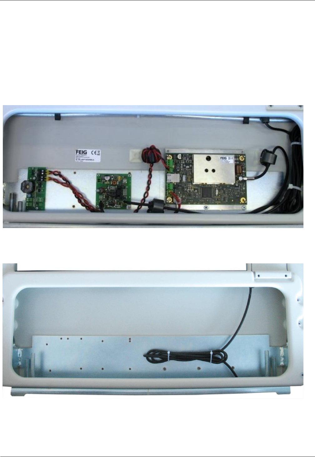
2 Performance Features of the ID ISC.ANT1300/680 Antennas
The ID ISC.ANT1300/680-A antenna is a version with integrated Manual Antenna Tuning Board ID
ISC.MAT , Long Range Reader ID ISC.LRM1002, Power Splitter Module ID ISC.PSM, Alarm LED
and Sounder mounted.
The ID ISC.ANT1300/680 Type B antenna is a version with Manual Tuning Board ID ISC.MAT
mounted.
The ID ISC.ANT1300/680 Type BL antenna is a version with Manual Tuning Board ID ISC.MAT
and Alarm LED mounted.
Up to
- two antennas with reader and power splitter as a single gate,
can be operated.
Depending on the antenna configuration, one, two or all three read orientations of the Smart Tags
and various antenna spacing (gate widths) are possible.
The ID ISC.ANT1300/680 –A/-B/-BL is a „figure-of-eight“ antenna with tuner and have been
optimized as transmitting and receiving antennas for the ID ISC.LRM1002 Reader. It is however
also possible to operate them with other Readers at a transmission frequency of 13.56 MHz and an
output impedance of 50 . The read ranges indicated in this document and the tuning procedures
may however then vary.
The antennas comprise the electrical antenna conductor, the housing, the ID ISC.MAT Manual
Antenna Tuner and the connection cable. The antennas are factory tuned to an impedance of 50
in a magnetically neutral environment at a distance of 90 cm. When installing in different ambient
conditions the antenna can be retuned using a suitable measuring device (e.g. SWR-Meter). After
tuning the antennas will retain their settings as long as the ambient conditions remain unchanged.
The antennas can be used for detecting both product and persons. It is suitable for installation
indoors or outdoors if weather-protected.
2.1 Available Antenna Types
The following products are currently available:
Antenna Type
Description
ID ISC.ANT1300/680-A
Antenna with Reader, Power Splitter and manual tuning board,
Alarm LED and Sounder and power supply
ID ISC.ANT1300/680-BL
Antenna with manual tuning board ID ISC.MAT and Alarm LED
ID ISC.ANT1300/680-B
Antenna with manual tuning board ID ISC.MAT
ID ISC.ANT1300680-SIG
Light signal with mounting material
ID ISC.ANT1300680-GPC
External People Counter
Table 1: Available Antenna Types and accessories
OBID i-scan® HF
Installation
ID ISC.ANT1300/680-A/-B/-BL
FEIG ELECTRONIC GmbH
Seite 8 von 47
M71104-9e-ID-B.doc
3 Installation and Wiring
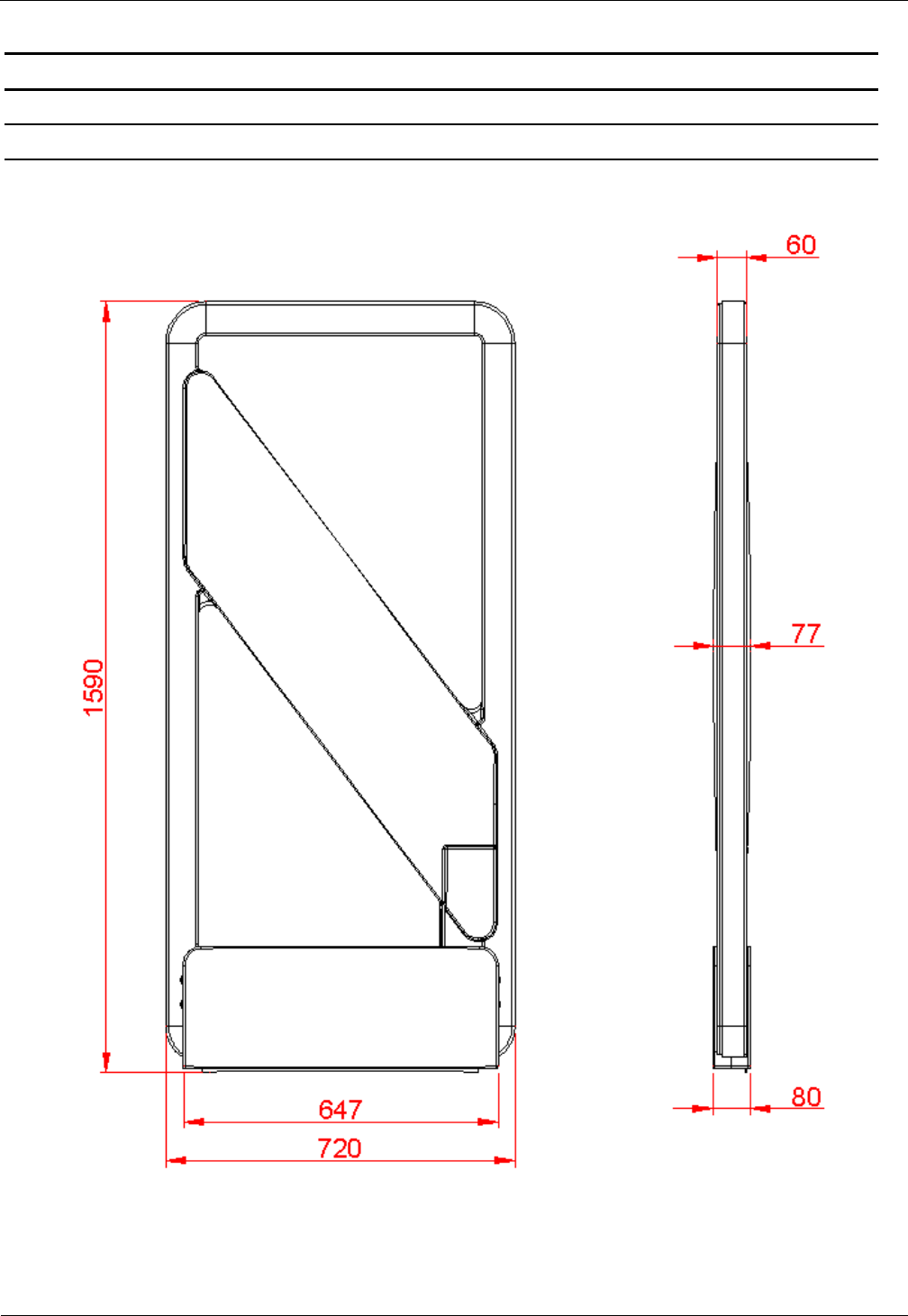
3.1 Dimensions of antenna
The outside dimensions of the antenna are shown in Fig. 1
Fig. 1: Antenna outside dimensions
All dimensions are in mm with general tolerance to ISO 2768 m (mean).
OBID i-scan® HF
Installation
ID ISC.ANT1300/680-A/-B/-BL
FEIG ELECTRONIC GmbH
Seite 9 von 47
M71104-9e-ID-B.doc
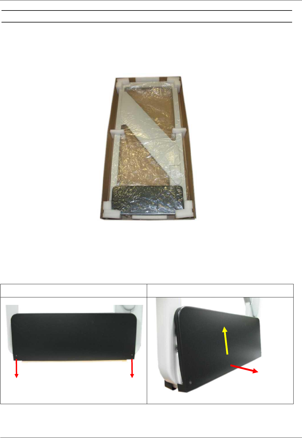
3.2 Mounting preparation
For assembly the antenna must be carefully unpacked. This is done as described in the following
steps:
1. Place the packed antenna on the floor with the top side facing up. Carefully open the box and
then remove the antenna.
Fig. 2: Antenna in its packaging
2. After that the antenna has to be placed carefully again on the floor. Now you must remove the
two fastening screws (hexagon socket width A/F2,5) of the antenna base cover and remove it
upwards. Fig. 3
Step 1
Step 2
Fig. 3: Opening the antenna base
OBID i-scan® HF
Installation
ID ISC.ANT1300/680-A/-B/-BL
FEIG ELECTRONIC GmbH
Seite 10 von 47
M71104-9e-ID-B.doc
3.3 Installing the antenna
Notes:
Before installing the antennas please read 4.1 Project Notes . The spacing of the antennas
in a gate depends on the antenna configuration.
If multiple antennas or gates are connected to different Readers, a minimum separation of
8 m must be kept between the antennas or gates. For shorter distances the antennas must
be shielded from each other. Otherwise the Reader range will be significantly reduced. The
antennas must have a minimum distance of 20 cm from all larger metal parts! At a distance
of less than 50 cm between the antenna and metal parts the Reader range will be
significantly reduced.
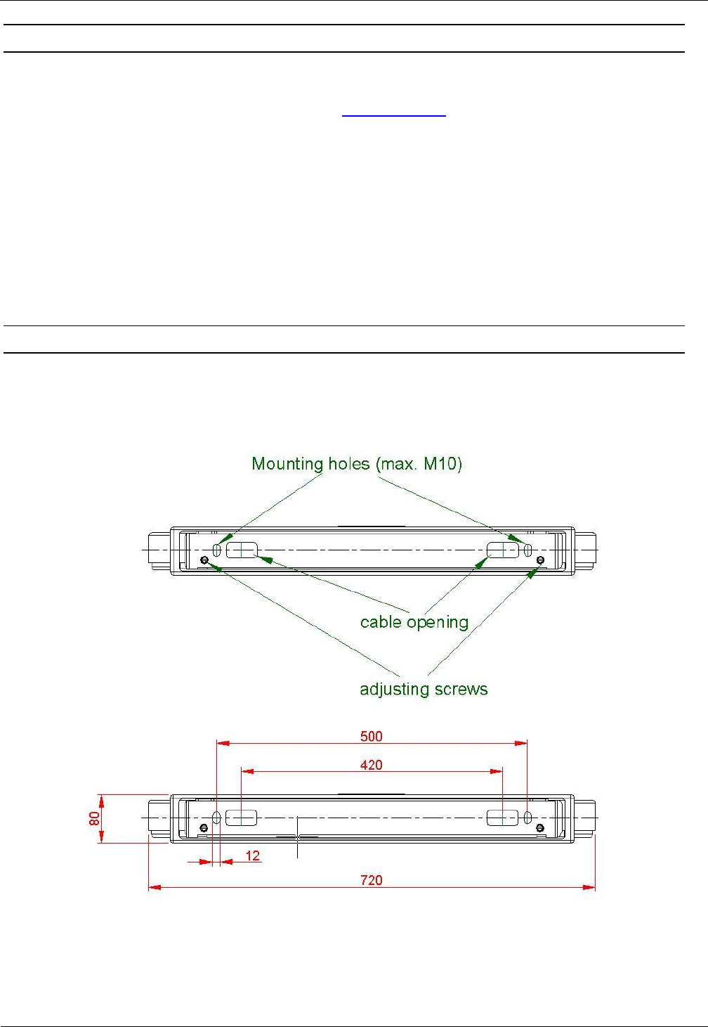
3.3.1 Drilling the Mounting Holes
If the position of the antennas has been marked or determined, the antenna base , which has to
be used as a hole template, can be used to mark and drill the mounting holes and the holes for the
cable entry. The dimensions are shown in Fig. 4:
Fig. 4: Floor plate dimensions
All dimensions are in mm with general tolerance to ISO 2768 m (middle).
OBID i-scan® HF
Installation
ID ISC.ANT1300/680-A/-B/-BL
FEIG ELECTRONIC GmbH
Seite 11 von 47
M71104-9e-ID-B.doc
The size and type of the screw anchors depends considerably on the strength of the base or floor.
The anchors should be capable of withstanding a permissible load of at least 5 kN per anchor for
all load directions (e.g. for concrete floor Hilti HVA anchors with HAS-(E) M8 threaded rod or Hilti
HIS-N M8 (5/16”) threaded inserts). The size of the mounting holes in the antenna is 10 mm (.39”).
The length of the anchors or bolts should be selected such that they extend at least 50 mm (2.0”)
and a maximum of 65 mm (2.6”) from the floor.
Please follow the mounting instructions of the anchor manufacturer!
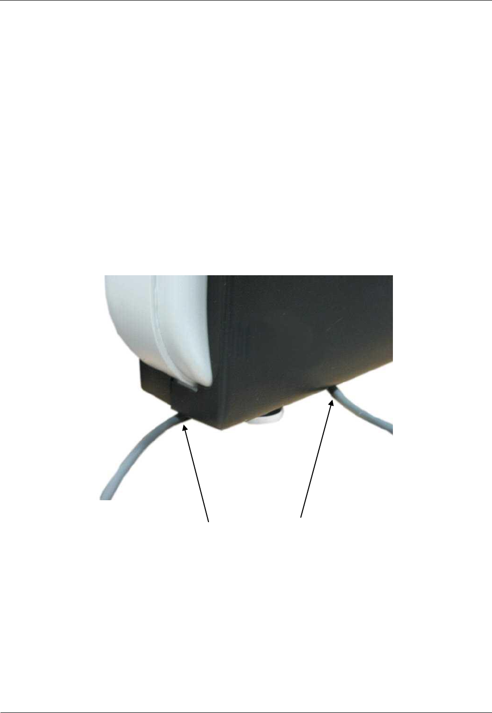
Two cable openings are provided for the necessary connection cable (see Fig. 4). The cable
openings are dimensioned such that up to 10 cables having a diameter of 6 mm can be passed
through each opening.
We recommend routing the antenna cables through the cable opening on the Power-Splitter or
Multiplexer side. All other cables such as the supply voltage and multiplexing cable should be
routed through the cable opening on the Reader side.
Alternatively the cables can be routed at the sides of the antenna bas like shown in Fig. 5
Fig. 5 Cable routing at the antenna sides
OBID i-scan® HF
Installation
ID ISC.ANT1300/680-A/-B/-BL
FEIG ELECTRONIC GmbH
Seite 12 von 47
M71104-9e-ID-B.doc
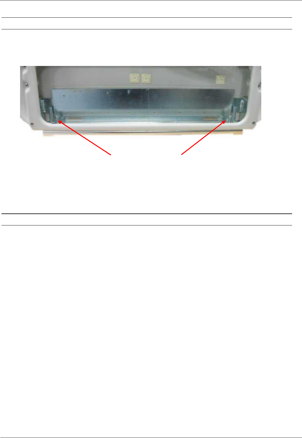
3.3.2 Installing the Antenna Base and Antenna Body
The antenna will be screwed on the floor. Use the adjusting screws (Fig. 6) to align the antenna
vertically.
Adjusting screws (hexagon socket width A/F5)
Fig. 6: Attaching and aligning the antenna
3.3.3 Connection of components
To built a gate configuration, you use one antenna Type A and one antenna Type B or BL.
OBID i-scan® HF
Installation
ID ISC.ANT1300/680-A/-B/-BL
FEIG ELECTRONIC GmbH
Seite 13 von 47
M71104-9e-ID-B.doc
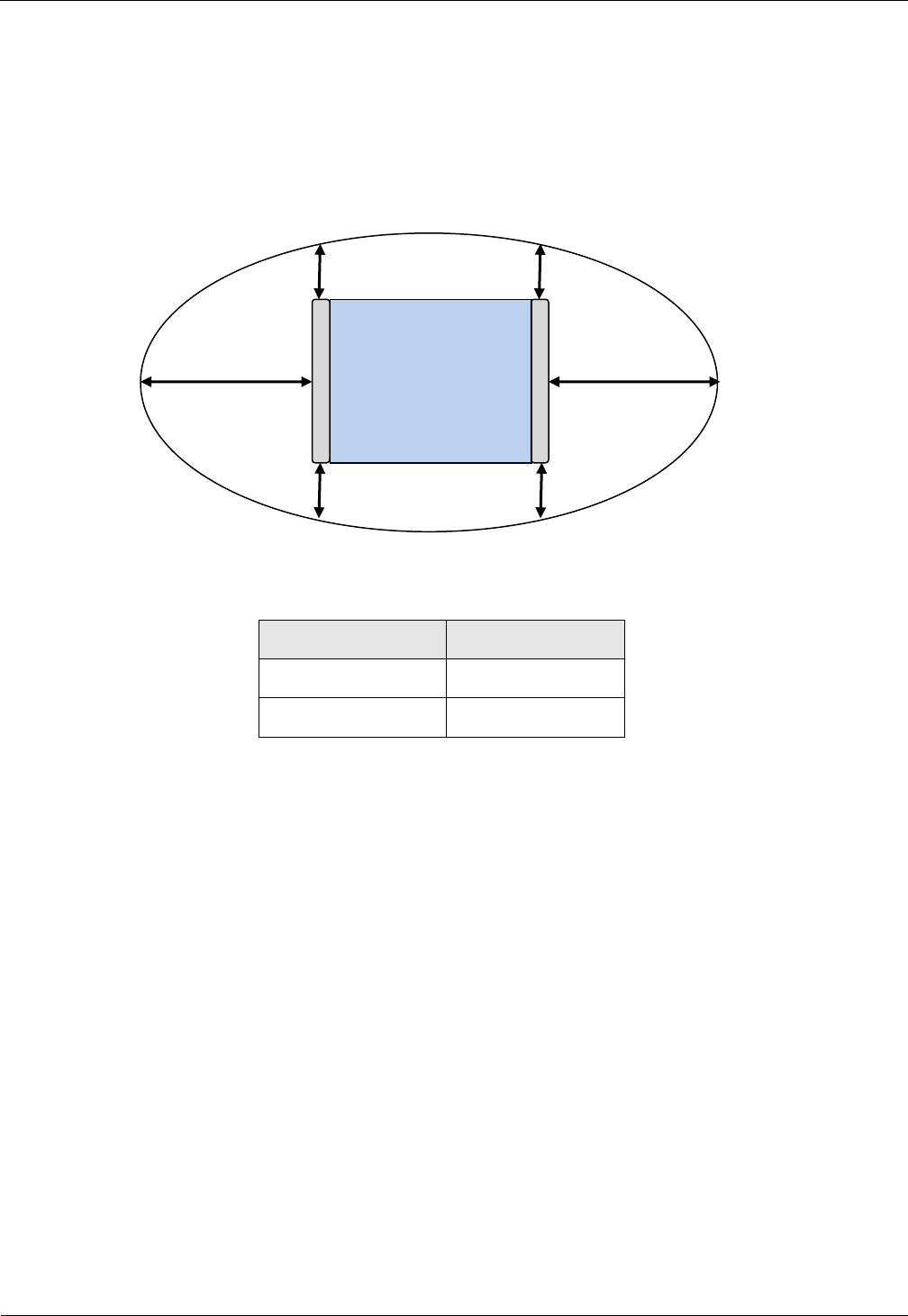
4 Typical Antenna Configuration (Gate Antenna with two Antennas)
The standard configuration of a gate with three-dimensional tag orientation consists of one
ID ISC.ANT1300/680-A with reader and power splitter and one ID ISC.ANT1300/680-B or BL. If a
tag moves, at horizontal line, through the gate, it can be read at least once. This ensures high
reliability of the antenna system.
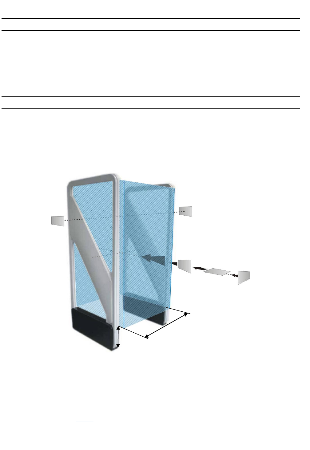
4.1 Project Notes
The antenna configuration as described allows detection of a tag moving horizontally through the
capture area of the gate. The tag orientation is non-critical. The tags are detected along a
horizontal axis of motion in certain regions within the antennas. The area of detection depends on
the tag orientation.
The size of the three-dimensional capture area of the antennas is shown in the sketch below.
Fig. 7: Capture area and tag orientation
Notes:
Note that the entire capture area of the antenna is larger than the three-dimensional area
shown in the drawing (Fig. 8). This means there are tag orientations in which the tag can be
detected outside the capture area.
GD
20
cm
OBID i-scan® HF
Installation
ID ISC.ANT1300/680-A/-B/-BL
FEIG ELECTRONIC GmbH
Seite 14 von 47
M71104-9e-ID-B.doc
To get a optimal performance the reader has to be configured and run in one of the
Automatic Modes (Buffered Read, Notification or Scan Mode).
If multiple gates are arranged with short distances between each other, these will mutually
interfere with each other which could cause a loss of read performance. This could be
reduced by installing a suitable shielding.
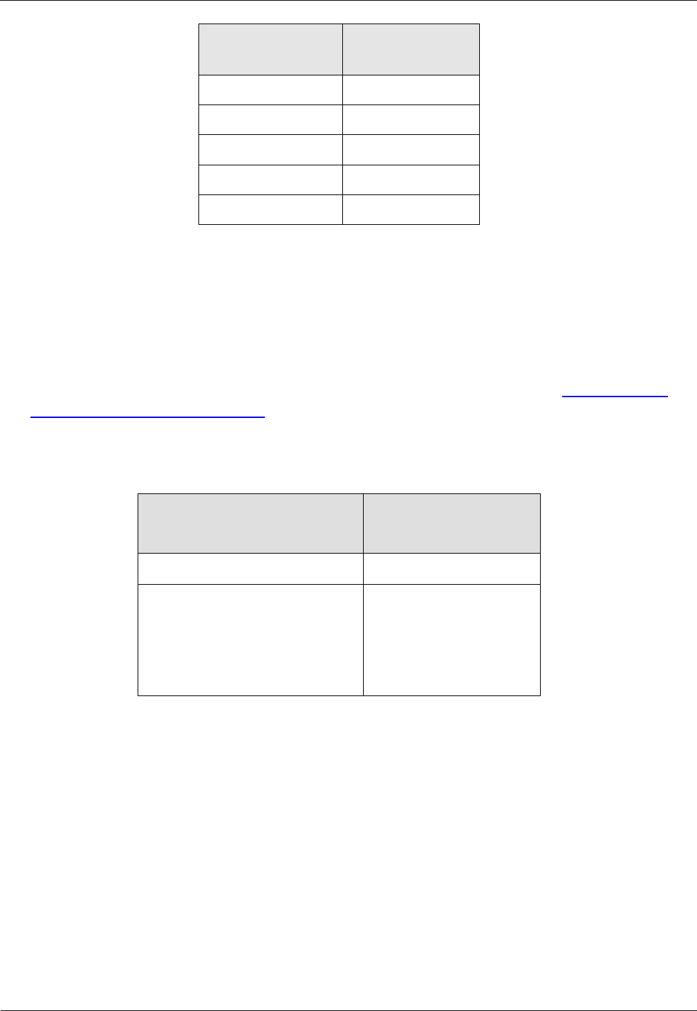
Fig. 8: Top view, capture area outside of the antenna gate
Direction
Minimum Distance
right, left (X=)
60 cm
front, behind (Y=)
25 cm
Table 2: Capture area, unintentional detection
To achieve three-dimensional capture of the tag in the capture area drawn above, the following
conditions must be met:
- The gate distance GD depends on the antenna configuration (see Table 4: Design notes).
- The tags should be at least ISO card size (46 mm x 75 mm).
- The activation field strength of the tags should be less than or equal to 60 mA/m.
- The distance from tag to tag should be greater than 10 cm. If the tag to tag distance is reduced,
the gate distance GD must be reduced correspondingly. This applies in particular to distances
under 5 cm.
- The maximum number of tags (serial number or data) depends on the traverse speed with
which the tags are brought through the capture area of the gate (see Table 4: Design notes).
The number of tags may be increased in the gate distance GD is correspondingly reduced and
the maximum speed adjusted accordingly.
- The antenna should be at least 50 cm from metal parts.
- The minimum distance between the antennas of a gate and antennas of RFID work station or
terminals (transmitting frequency 13,56 MHz) should be:
X
X
Y
Y
OBID i-scan® HF
Installation
ID ISC.ANT1300/680-A/-B/-BL
FEIG ELECTRONIC GmbH
Seite 15 von 47
M71104-9e-ID-B.doc
Transmitted
output power
Minimum Distance
< 0.5 W
1 m
0.5 W-1.0 W
2 m
1.1 W – 2.0 W
3 m
> 2 W
4 m
>= 4 W
8 m
Table 3: Minimum Distances
- There should be no interference of the Reader from other electrical devices in the environment.
The Noise Level difference should be less than 20 mV.
- The ID ISC.LRM1002 Reader should be set to an RF power of 5 watts.
- When using ISO 15693 transponders, the Readers should be set as described in 4.2.6 Reader
Configuration with Power Splitter.
- If multiple gates are operated at the same time at a distance of less than 8 m, a loss of read
performance due to high interferences could happen. This could be reduced by installing a
suitable shielding.
Gate with antenna
Type A and Type B/BL
Gate distance GD
90 cm
Number of tags at traverse
speed 1 m/s
- Read serial number
- Read data
16
8
Table 4: Design notes
Supplementary equipment (e.g. light barrier, lighting, etc.), mounted directly on the antenna or in
the immediate vicinity of the antenna can interference with the functioning of the system.
A minimum distance of 20 cm is required.
Electrical cable, directly at the antenna or in the immediate vicinity of the antenna, can be cause
interference. A minimum distance of 20 cm is required.
A minimum distance of 65cm between the two gate antennas is required.

OBID i-scan® HF
Installation
ID ISC.ANT1300/680-A/-B/-BL
FEIG ELECTRONIC GmbH
Seite 16 von 47
M71104-9e-ID-B.doc
4.2 Gate Configuration and Setup using Antennas Type –A and Type –B/-BL
4.2.1 Required Components
To construct the gate you need the following components:
- Qty. 1 ID ISC.ANT1300/680 Antenna Type A
(Incl. Qty. 1 ID ISC.NET24V-B Power Supply Unit)
- Qty. 1 ID ISC. ANT1300/680 Antenna Type B or BL
- Power cable, interface cable and connection cable for the DC power supplies (2-wire,
twisted)
- Mounting materials (screws, anchors)
To calibrate the Reader you will need the software
- ISOStart Version 2012 Version 9.02 or newer
on a personal computer running under Microsoft® Windows®.
and for tuning the antennas a suitable measuring device (e.g. SWR-Meter)
The service can be downloaded at the Download Area of the Homepage www.feig.de.
OBID i-scan® HF
Installation
ID ISC.ANT1300/680-A/-B/-BL
FEIG ELECTRONIC GmbH
Seite 17 von 47
M71104-9e-ID-B.doc
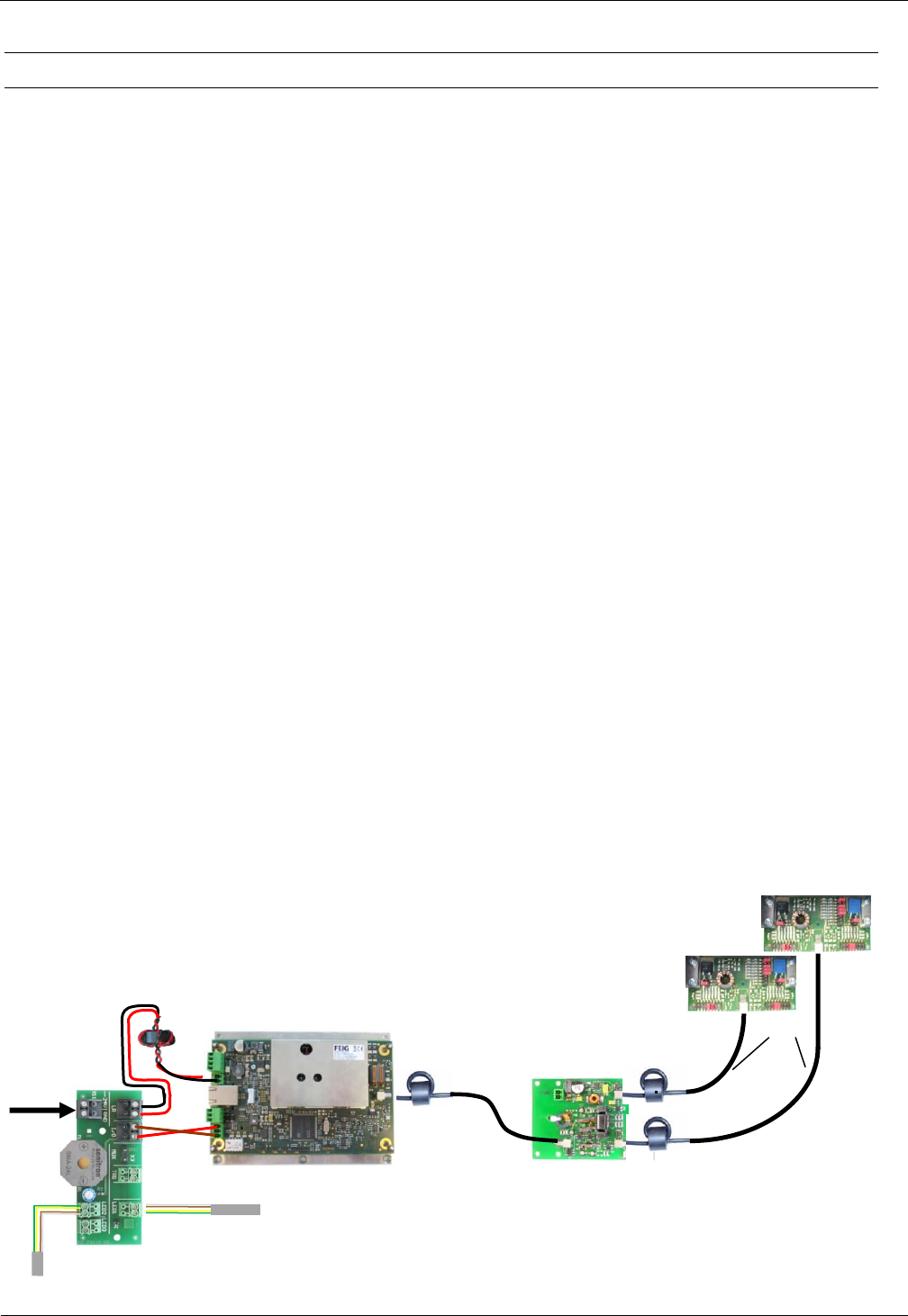
4.2.2 Configuration of a Gate antenna with Power Splitter
Connect the components as shown in
Fig. 9. Nearly, all cable should be mounted already. Normally, the antenna cable from antenna
Type B has to connect to Output X3 at the power splitter and the 24V DC power supply to X11 of
the terminal board only. Optional the alarm LED of the antenna Type BL could be connected to
X12/LED2 of the terminal board.
2 Tuning Boards of
Antennas ID ISC.ANT1300/680
X2
X3
X1
3,60m
Power Splitter
ID ISC.ANT.PSM-B
X1
1,35m
Long Range Reader
ID ISC.LRM1002-E
IN1
X4, Pin1+3
Alarm LED board
Alarm LED board BL
(optional)
24V DC
Power Supply
OBID i-scan® HF
Installation
ID ISC.ANT1300/680-A/-B/-BL
FEIG ELECTRONIC GmbH
Seite 18 von 47
M71104-9e-ID-B.doc
Fig. 9: Connecting the components for a gate consisting of two antennas, reader and power splitter
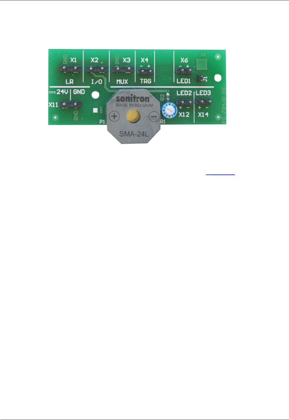
Fig. 10:Terminal board
An overview of the terminal board assignment is given in 6.Annex A
OBID i-scan® HF
Installation
ID ISC.ANT1300/680-A/-B/-BL
FEIG ELECTRONIC GmbH
Seite 19 von 47
M71104-9e-ID-B.doc
Note:
A reverse polarity could damage the device or the In-/Outputs.
The coax cables have fixed lengths and may not be shortened and therefore need to be tied into
small loops (see). Tie all cables as far away from the antenna conductor as possible. The cables
must never be allowed to contact the antenna conductor. The cable from antenna type B/BL to the
antenna type AL should preferably be connected shortly. Unused cable lengths are possible should
be tied in antenna B/BL type.
Fig. 11 Connection of the components in an antenna Type A
Fig. 12 Unused coaxial cables are tied in antenna Type B/BL
OBID i-scan® HF
Installation
ID ISC.ANT1300/680-A/-B/-BL
FEIG ELECTRONIC GmbH
Seite 20 von 47
M71104-9e-ID-B.doc
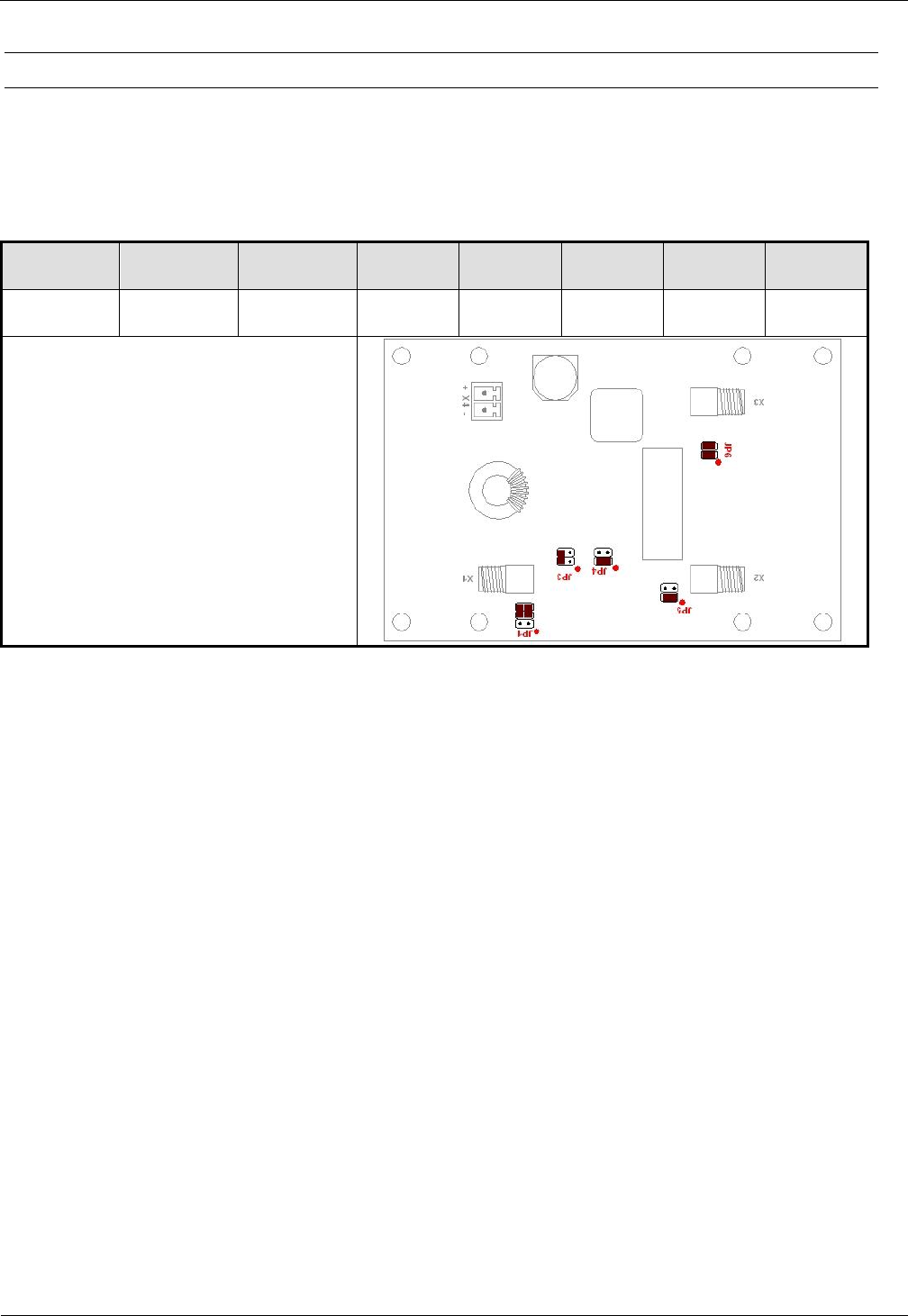
4.2.3 Setting the Power Splitter
Set the jumpers on the Power Splitter as shown in Table 5:Power Splitter setting. More information
about setting the ID ISC.ANT.PSM-B Power Splitter can be found in the corresponding installation
manual (M40402-xde-ID-B).
Table 5:Power Splitter setting
Trans-
former
Power
Splitter
Phase
shifter
JP1
JP3
JP4
JP5
JP6
not used
X
X
3-5
4-6
2-4
1-2
1-2
1-2
3-4
Power Splitter with 90° phase shifter
X1: Reader
X2: Antenna
X3: Antenna
X4: 12-24V DC for Antenna with dyn.
antenna tuner ID ISC.DAT
Fig. 13 Jumper Settings for Power Splitter
OBID i-scan® HF
Installation
ID ISC.ANT1300/680-A/-B/-BL
FEIG ELECTRONIC GmbH
Seite 21 von 47
M71104-9e-ID-B.doc
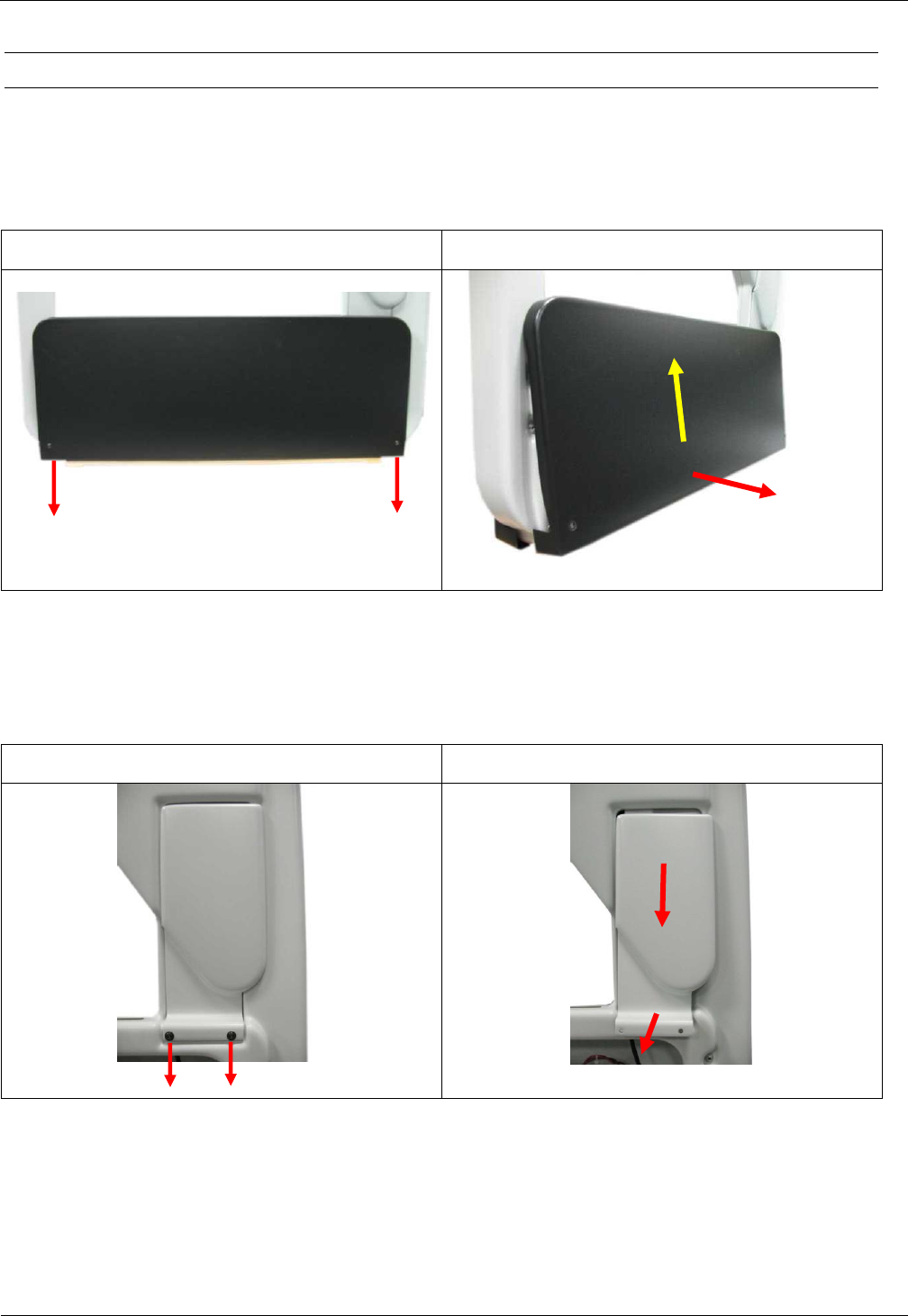
4.2.4 Setting the Antenna Tuner
To check the settings of the antenna tuner the antenna base has to be opened. For that, remove
the two fastening screws (hexagon socket width A/F2,5) of the antenna base cover and move it
upwards. Fig. 14
Step 1
Step 2
Fig. 14: Opening of the antenna base
Now remove the to fastening screws (hexagon socket width A/F2,5) of the antenna tuner cover and
move it downwards. Fig. 15
Step 3
Step 4
Fig. 15 Removing the antenna tuner cover
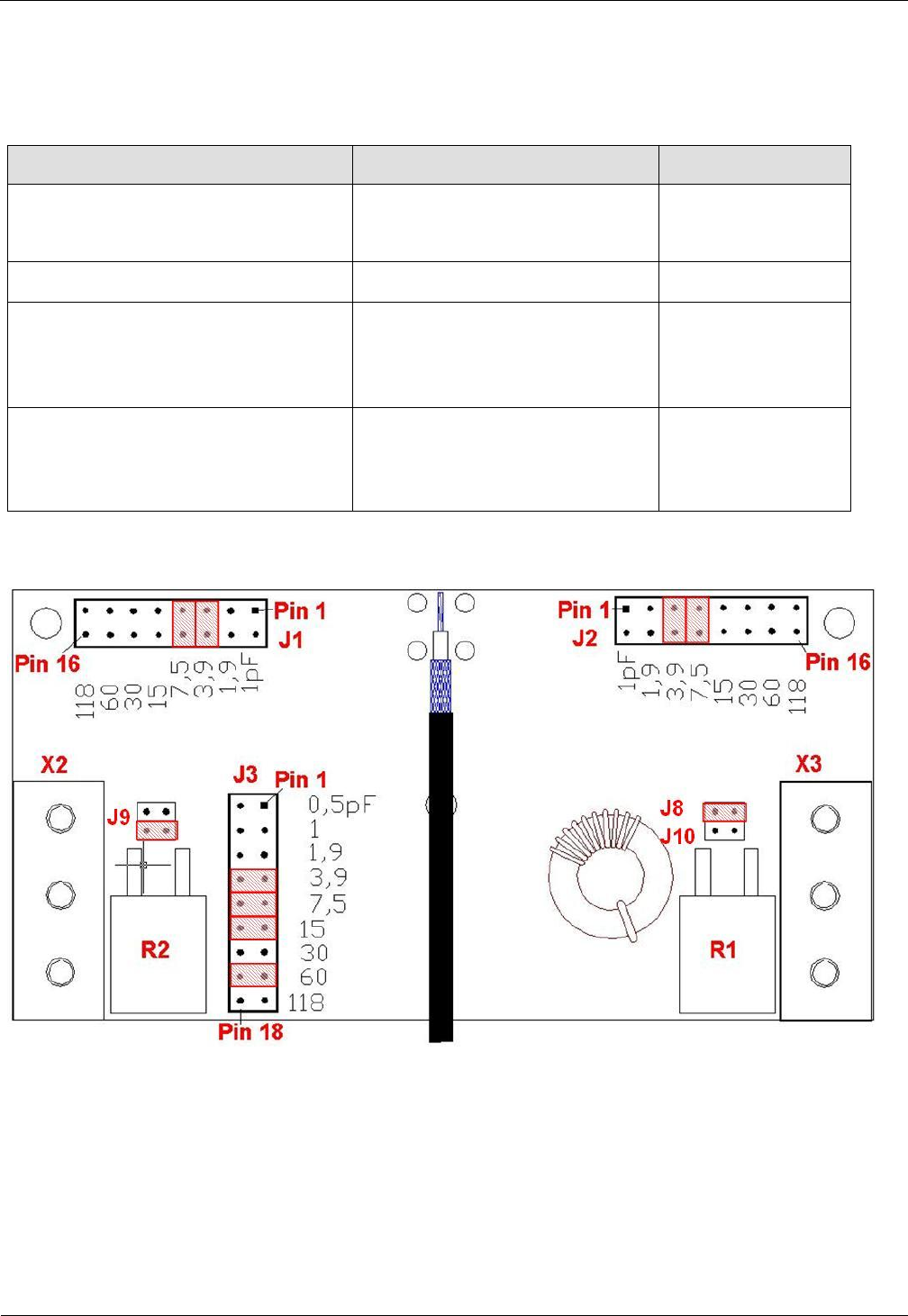
OBID i-scan® HF
Installation
ID ISC.ANT1300/680-A/-B/-BL
FEIG ELECTRONIC GmbH
Seite 22 von 47
M71104-9e-ID-B.doc
The ID ISC.ANT1300/680 antennas are factory set to the best value of impedance Z= 50 +/-5
Ohms and Phase =0° +/-5°
Table 6: Jumper settings for Antenna Tuner
Function
Jumper
Position
0,5 Q resistor
JP10
JP8
open
closed
1 Q resistor
JP9:3-4
closed
Capacitor C1 => JP1 + JP 2
1-2, 3-4, 9-10, 11-12,
13-14, 15-16
5-6, 7-8
open
closed
Capacitor C2 => JP3
1-2, 3-4, 5-6, 13-14, 17-18,
7-8, 9-10,11-12, 15-16
open
closed
The factory settings of the capacitor jumpers C1 and C2 could be different as shown in this
table/figure due to parts tolerances.
Fig. 16 Jumper Settings for Tuning Board MAT
Verify these settings with a suitable measuring device (e.g. SWR-Meter) after installing the
antennas. More on setting the ID ISC.MAT antenna tuner can be found in the corresponding
installation manual (M70101-xe-ID-B).
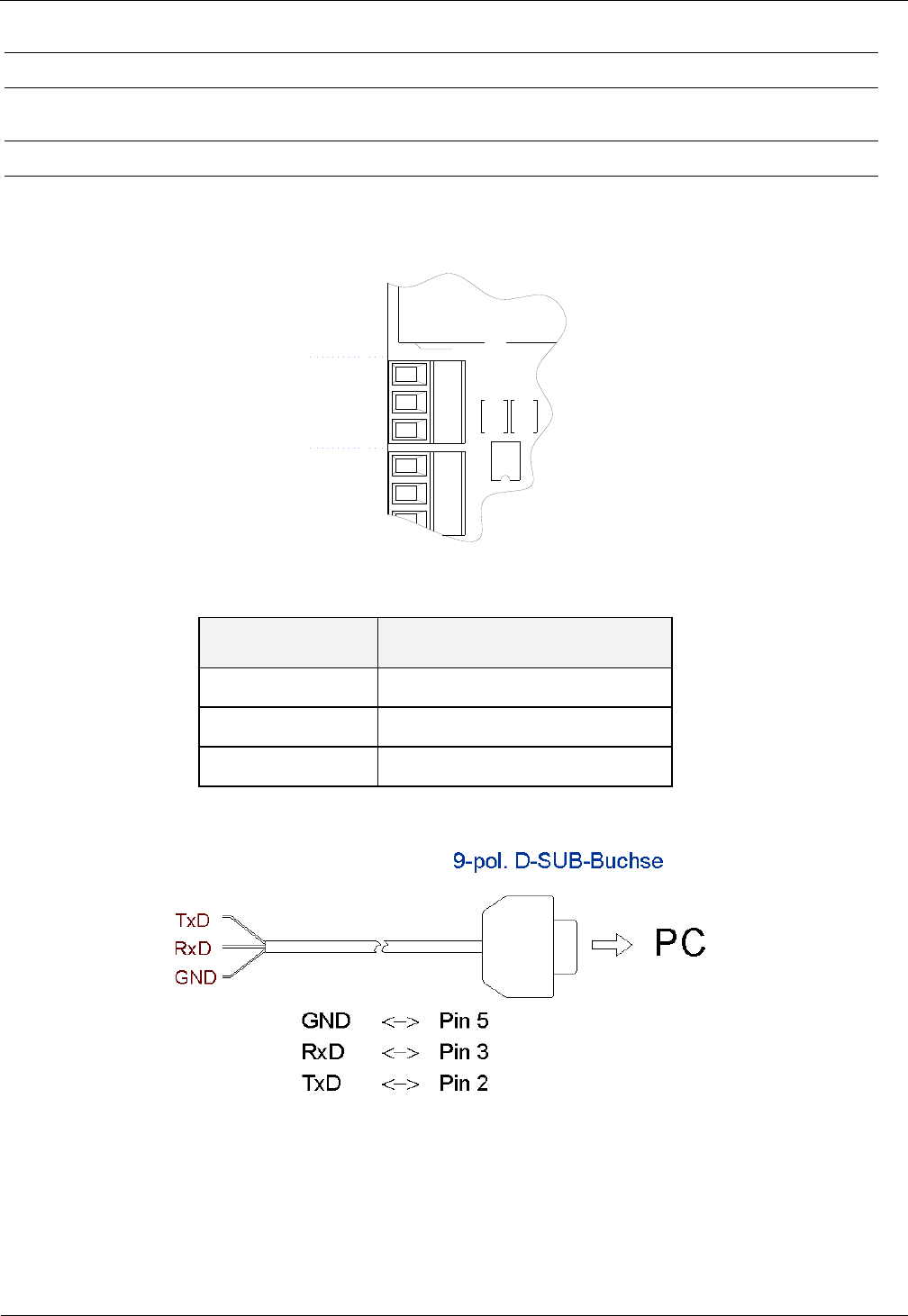
OBID i-scan® HF
Installation
ID ISC.ANT1300/680-A/-B/-BL
FEIG ELECTRONIC GmbH
Seite 23 von 47
M71104-9e-ID-B.doc
4.2.5 Interface Connections
4.2.5.1 RS 232
The RS232 interface is connected on X4. The transmission parameters can be configured by
means of software protocol.
TxD
RxD
GND
X4
X6
Figure 1: RS232 interface pin-outs on X4
Kurzzeichen
Description
TxD
RS232 – (Transmit)
RxD
RS232 – (Receive)
GND
RS232 – (Ground)
Table 7: Pin assignment of the RS232-Interface
Fig. 17: Wiring example for connecting the RS232 interface
Note:
If there is an USB/RS232 converter used on the PC/Notebook side, we recommend to
increase the „Char Timeout Multiplier“ parameter in the COM-Port settings from „1“ to
about „5“.
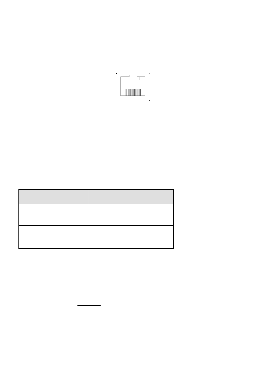
OBID i-scan® HF
Installation
ID ISC.ANT1300/680-A/-B/-BL
FEIG ELECTRONIC GmbH
Seite 24 von 47
M71104-9e-ID-B.doc
4.2.5.2 LAN / TCP/IP
The Reader has an integrated 10 / 100 Base-T network port for an RJ-45. Connection is made on
X3 and has an automatic “Crossover Detection” according to the 1000 Base-T Standard.
With structured cabling CAT 5 cables should be used. This ensures a reliable operation at 10 Mbps
or 100 Mbps.
The prerequisite for using TCP/IP protocol is that each device has a unique address on the net-
work. All Readers have a factory set IP address.
Network
Address
IP-Adresse
192.168.10.10
Subnet-Mask
255.255.255.0
Port
10001
DHCP
OFF
Table 8 Standard factory configuration of the Ethernet connection
Note:
The Reader TCP/IP interface has a DHCP option.
It is recommended to use a shielded twisted pair STP CAT5 cable.
More Information about the interfaces you will find in the manual M20413-xde-ID-B of the reader.
X3
Figure 2: LAN interface for host communication
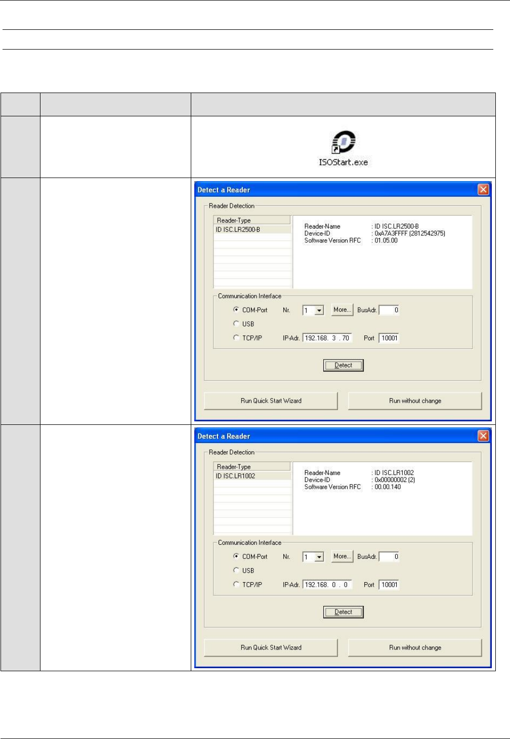
OBID i-scan® HF
Installation
ID ISC.ANT1300/680-A/-B/-BL
FEIG ELECTRONIC GmbH
Seite 25 von 47
M71104-9e-ID-B.doc
4.2.6 Reader Configuration with Power Splitter
To tune the antennas, open the ISOStart software and read out the current configuration of the
Reader:
Step
Action
Note
1
Start ISOStart Software
2
Select „Detect“
3
Select „Keep Configuration
unchanged and exit Wizard“
and click on „Exit“
Note:
This has to be done at each
start of ISO-Start program
otherwise the configuration
of the reader will be changed
by the wizard.
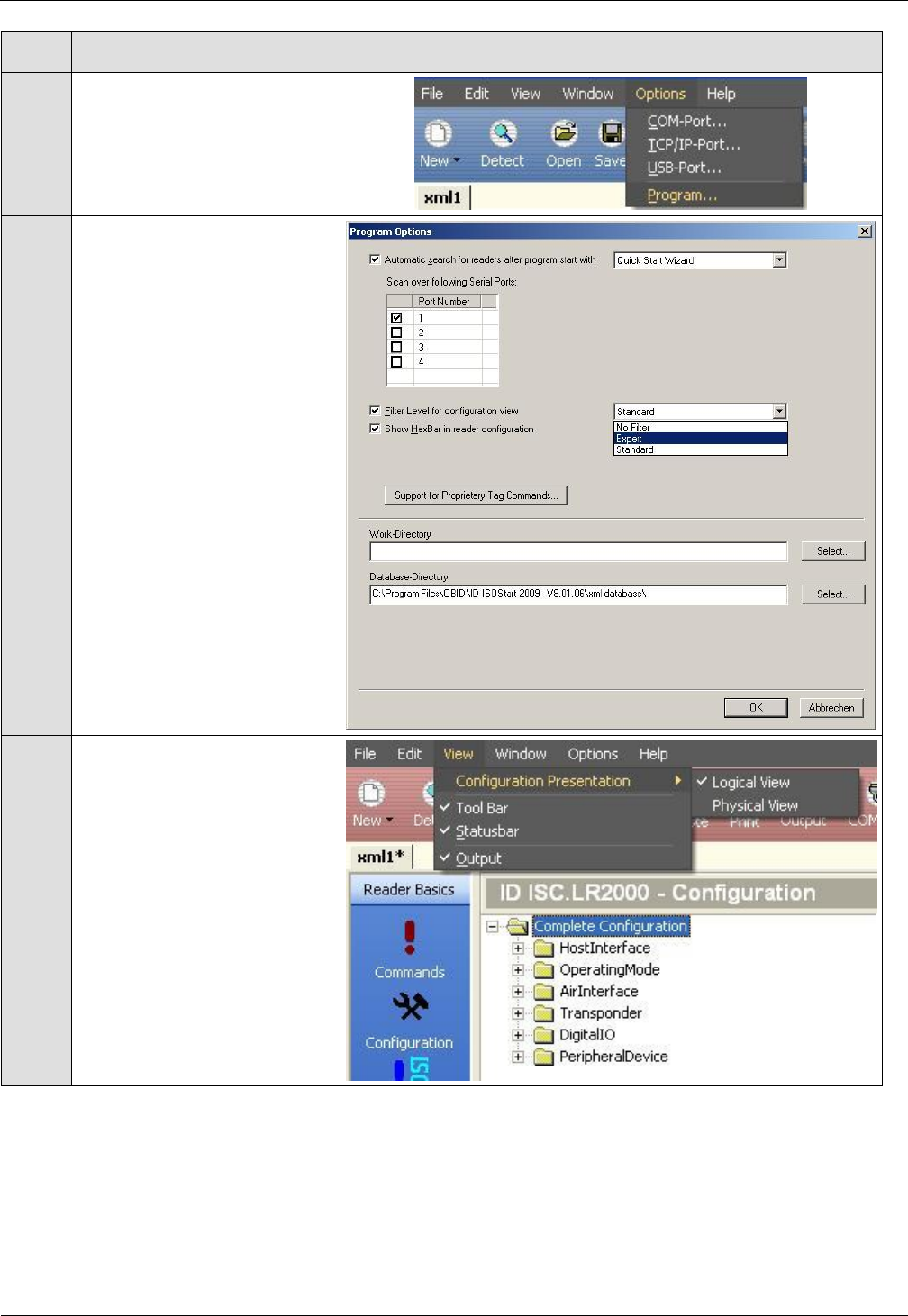
OBID i-scan® HF
Installation
ID ISC.ANT1300/680-A/-B/-BL
FEIG ELECTRONIC GmbH
Seite 26 von 47
M71104-9e-ID-B.doc
Step
Action
Note
4
Select „Options => Program“
5
Select „Expert Mode“ and
confirm with OK.
6
Select “Logical View”
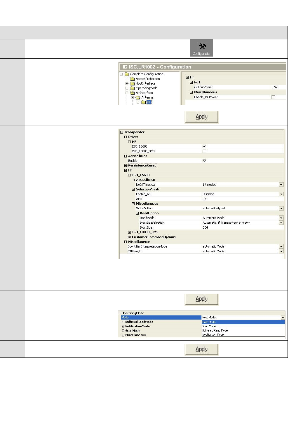
OBID i-scan® HF
Installation
ID ISC.ANT1300/680-A/-B/-BL
FEIG ELECTRONIC GmbH
Seite 27 von 47
M71104-9e-ID-B.doc
Afterwards set the operating power, Transponder Parameters and ISO Host Mode:
Step
Action
Note
1
Select “Configuration”
2
Air Interface:
“Output -Power” = 5W
3
Set by clicking on „Apply“.
4
Transponder:
Configure the parameters as
following:
„Driver“ – here ISO 15693
„Anticollision“ – enable
„No of Timeslots“ –
1 timeslot
„Data Coding“ – 1 of 4
„AFI“ – Disabled
Note: National RF regulations may require different
settings. 4.6 Configuring the Reader in accordance with
national RF regulations
5
Set by clicking on „Apply“.
6
Operating Mode:
For antenna tuning the reader
has to be set to „Host Mode“.
7
Set by clicking on „Apply“.
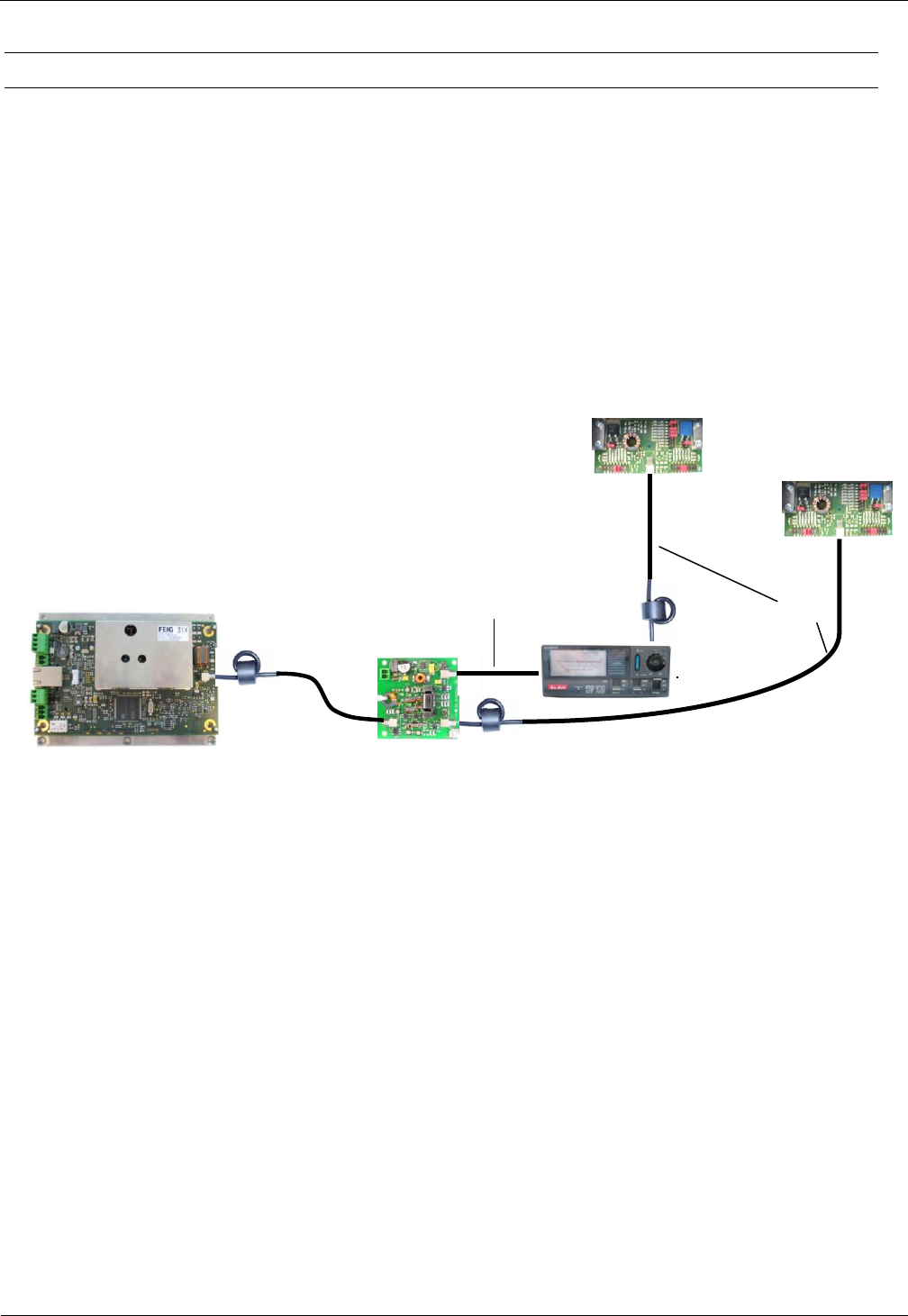
OBID i-scan® HF
Installation
ID ISC.ANT1300/680-A/-B/-BL
FEIG ELECTRONIC GmbH
Seite 28 von 47
M71104-9e-ID-B.doc
4.2.7 Tuning the Gate Antenna with Power Splitter
For tuning the antennas you will need a suitable measuring device (e.g. SWR-Meter or SWR-
Analyzer) The SWR-Meter has to be looped in between power splitter and antenna with a 30cm
coax cable RG58. (see Fig. 18) The reader must be set to ISO-Host Mode. If necessary the anten-
nas could be tuned by setting or removing the jumpers of the capacitors C1 and C2. You should
start the tuning with the lowest values of the capacitors and then to use the next higher values.
First start with capacitor C2. If there is no change anymore you should continue with capacitor
C1.The standing-wave ratio should be at least 1:1,2 or better. .50 +/-5 Ohm Phase 0° +/-5° at the
SWR-Analyzer.
This has to be done for both antennas.
Fig. 18 Tuning the antennas with a SWR-Meter
X3
X1
Power Splitter
ID ISC.ANT.PSM-B
ANT1
1,35m
Long Range Reader
ID ISC.LRM1002-E
IN1
X2
3,60m
30cm
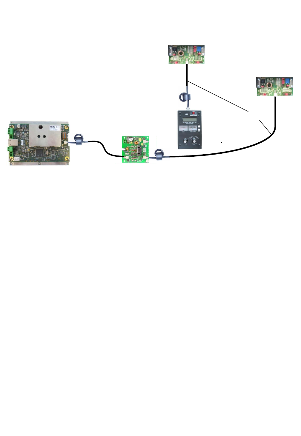
OBID i-scan® HF
Installation
ID ISC.ANT1300/680-A/-B/-BL
FEIG ELECTRONIC GmbH
Seite 29 von 47
M71104-9e-ID-B.doc
If you tune antennas with a SWR-Analyzer, you must connect the antennas directly to the SWR-
Analyzer. The reader should be switched off during the tuning. The tuning has to be done as de-
scribed above.
Fig. 19 Tuning the antennas with a SWR- Analyzer
For recommended devices and possible vendors see: 6.2 Sources of supply measuring instru-
ments and accessories
X3
X1
Power Splitter
ID ISC.ANT.PSM-B
X1
1,35m
Long Range Reader
ID ISC.LRM1002-E
IN1
X2
3,60m
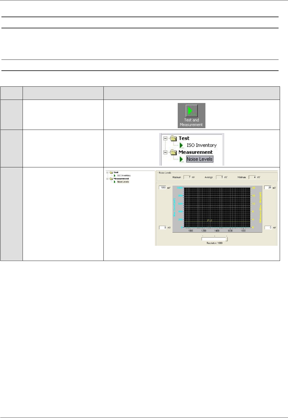
OBID i-scan® HF
Installation
ID ISC.ANT1300/680-A/-B/-BL
FEIG ELECTRONIC GmbH
Seite 30 von 47
M71104-9e-ID-B.doc
4.3 Testing the Gate Antenna
After tuning the gate antenna, you can check for proper function using a Reader, the ISOStart
service software and a Transponder. Here the Noise Level and performance of the gate are tested.
4.3.1 Checking the Noise Level
Step
Action
Note
1
Activate “Test and
Measurement”
2
Select „Noise Level“ and
start by clicking on „Start“
3
Normal Noise Level values:
Average:
< 30mV
Difference (Max-Min):
< 20mV
If the values are not met, check the following:
Are all cables pulled tight and do they make good contact?
Were the ring cores installed in the antenna cable?
Were the cables routed as specified?
Are other RFID systems installed nearby?
Are there large metal parts near the antenna (distance < 1.0 m)?
Are there devices nearby which may emit noise interferences (larger machines or wireless
devices)?
Are there interferences from the mains?
To determine which devices may be disturbing the gate, briefly disconnect them from the mains.
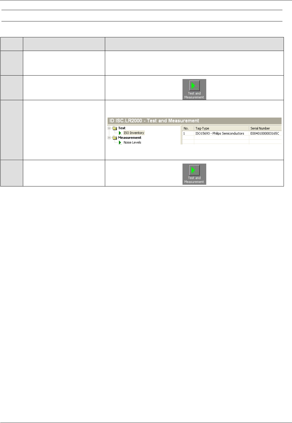
OBID i-scan® HF
Installation
ID ISC.ANT1300/680-A/-B/-BL
FEIG ELECTRONIC GmbH
Seite 31 von 47
M71104-9e-ID-B.doc
4.3.2 Reading a Serial Number
Step
Action
Note
1
Attach a tag to an antenna
Use adhesive tape, for example
2
Select „Test and
Measurement“
3
Select „ISO Inventory“
function and activate by
clicking on „Start“.
The serial number and tag
type will be shown in the
display.
4
Repeat Step 1 to 3 for the
opposite antenna
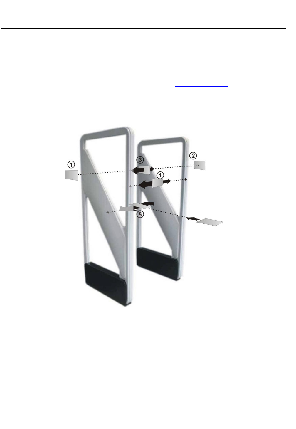
OBID i-scan® HF
Installation
ID ISC.ANT1300/680-A/-B/-BL
FEIG ELECTRONIC GmbH
Seite 32 von 47
M71104-9e-ID-B.doc
4.3.3 Testing the performance
For testing the performance you must switch the reader to one of the Automatic Modes.
See 4.5 Activating the Automatic Mode
A read transponder will be displayed by a blue LED on the reader or by the LED light and the
Sounder of the antenna. See also 4.4 Connecting and Setting the
In this test the capture area of the gate antenna described in 4.1 Project Notes is checked. For
other tags or other configurations the indicated ranges and read areas may differ accordingly.
Fig. 20: Performance Test of the gate antenna
The test begins by checking the read range outside the gate (see Fig. points and ), assuming
the configuration and locality permit it. If the tag is oriented parallel to the antenna towards the
outside, a read range of 65 to 75 cm should be achieved.
The three tag orientations are checked inside the gate. This corresponds to the lines and
orientations . Now slowly move the tag in the vertical and parallel direction with respect to
the antenna along the line from one side to the other. The tag should always be read.
Then repeat this along the line in the vertical tag direction transverse to the antenna and on the
line in the horizontal tag orientation. Here again the tag should always be read.

OBID i-scan® HF
Installation
ID ISC.ANT1300/680-A/-B/-BL
FEIG ELECTRONIC GmbH
Seite 33 von 47
M71104-9e-ID-B.doc
The tag should be read within the gate when moving horizontally through the gate in all
three read orientations.
If one or more „holes“ are detected, check the noise values on the Reader (see 4.3.1 Checking the
Noise Level) .
The following may result in faulty readings:
Antenna improperly installed (orientation, antenna distance, check cabling)
Metal near the antennas is detuning or interfering with them.
The antennas are not properly tuned.
Noise level too high (Vmax – Vmin 20 mV)
Transponder too insensitive, detuned or defective
Reader improperly configured (transmitting power, transponder type, modulation, transponder
parameters, etc.).
A cable is defective or has a poor contact.
Reader, Power Splitter or antenna defective.
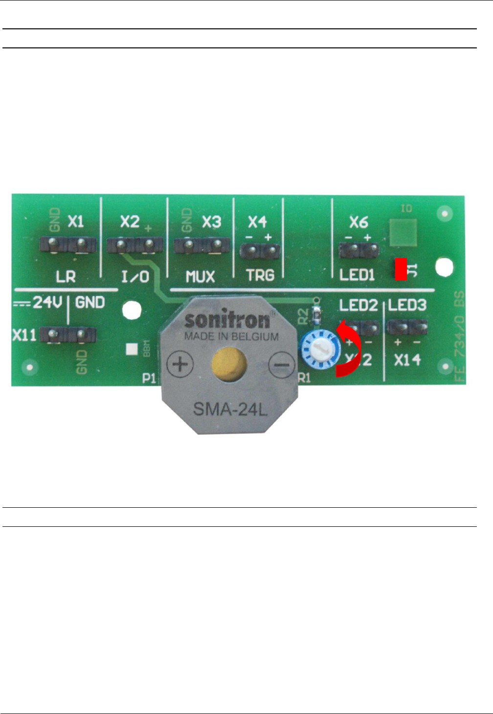
OBID i-scan® HF
Installation
ID ISC.ANT1300/680-A/-B/-BL
FEIG ELECTRONIC GmbH
Seite 34 von 47
M71104-9e-ID-B.doc
4.4 Connecting and Setting the Indicators
The solution provided here presumes that all alarm indicator (Sounder and LED) are wired in
parallel and switched through the relay X6 on the ID ISC.LRM1002 Reader. The pulse duration can
be set (Digital IO/RELAY NO1) between 100 ms and 65535 s by adjusting the Reader
configuration. Relay X11 provides a changeover contact for low voltages.
The acoustic indicator, the sounder, is installed on the terminal board as shown in Fig. 21. The
volume can be adjusted with the potentiometer on the terminal board.
Jumper J1 on the terminal board has to be set to activate the sounder and the alarm LED simulta-
neous by the relay.
Fig. 21: Volume adjusting
The mounting of the light signal ID ISC.ANT1300680-SIG is described in M90800-xde-B.pdf
4.4.1 Connecting the Alarm LED
The Alarm LED of the antenna Type BL must be connected with X2/LED2 on the terminal board.
Attention! Take care of polarity.
Notes:
The relay outputs are dimensioned for max. 24 V DC / 1 A.
The relay outputs are intended only for switching resistive loads. If an inductive load is used,
the relay contacts must be protected by an external protection circuit.
Reversing the polarity or overloading the outputs will destroy them.
See also Installation Manual M20413-xde-ID-B.pdf ID ISC.LRM1002
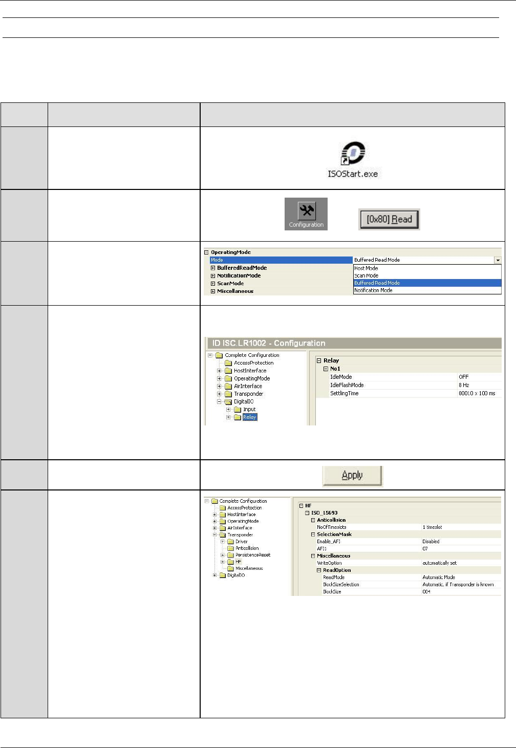
OBID i-scan® HF
Installation
ID ISC.ANT1300/680-A/-B/-BL
FEIG ELECTRONIC GmbH
Seite 35 von 47
M71104-9e-ID-B.doc
4.4.2 Reader Setting for Indicator
The ISOStart software can be used to set the Reader configuration so that relay X11 opens or
closes when a Transponder is read.
Step
Action
Note
1
Start ISOStart Software
2
Select “Configuration” and
click on “Read” to read the
complete configuration.
3
Operating Mode
Select Buffered Read Mode.
4
Digital IO:
Output Idle Mode: OFF
Idle Flash Mode: 1Hz
Setting Time:
with „Setting Time“ set
time of relay 1 for alarm
duration.
(10 means 1 second)
(e.g. 10 x 100ms)
5
Set by clicking on „Apply“.
6
Transponder
If the alarm should occur by
a transponder with valid AFI
byte, you have to configure
the reader as follow:
ISO-15693 – Selection Mask
Set “Enable AFI”
Set the value for the AFI in
field “AFI1” (e.g. 07)
Note:
Up to four different AFI
values could be set.
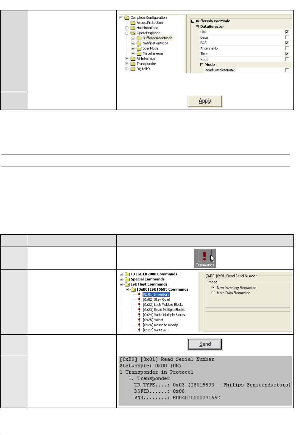
OBID i-scan® HF
Installation
ID ISC.ANT1300/680-A/-B/-BL
FEIG ELECTRONIC GmbH
Seite 36 von 47
M71104-9e-ID-B.doc
7
Operating Mode
If the alarm should occur by
an EAS, you have to
configure the reader as
follow:
Set “EAS”
8
Set by clicking on „Apply“
4.4.3 Programming a Transponder with the AFI Byte
If the Transponders will remain on the object when leaving the storage location, they must first be
cancelled. This is generally done by writing to a particular area of the Transponder.
The AFI byte (Application Family Identifier) is useful for this purpose, since it is contained in nearly
all Transponder models in the ISO15693 family. To cancel, simply write a different code to the
Transponder than for valid Transponders which trigger an alarm.
Step
Action:
Note:
1
Select „Commands“
2
Place the Transponder in the
antenna field (Antenna 1)
Select [0x01] Inventory
Mode: New Inventory
Requested
3
Read UID by clicking on
„Send“
4
The serial number, DSFID
and Transponder type are
displayed in a window.
Write down the serial number
of the Transponder
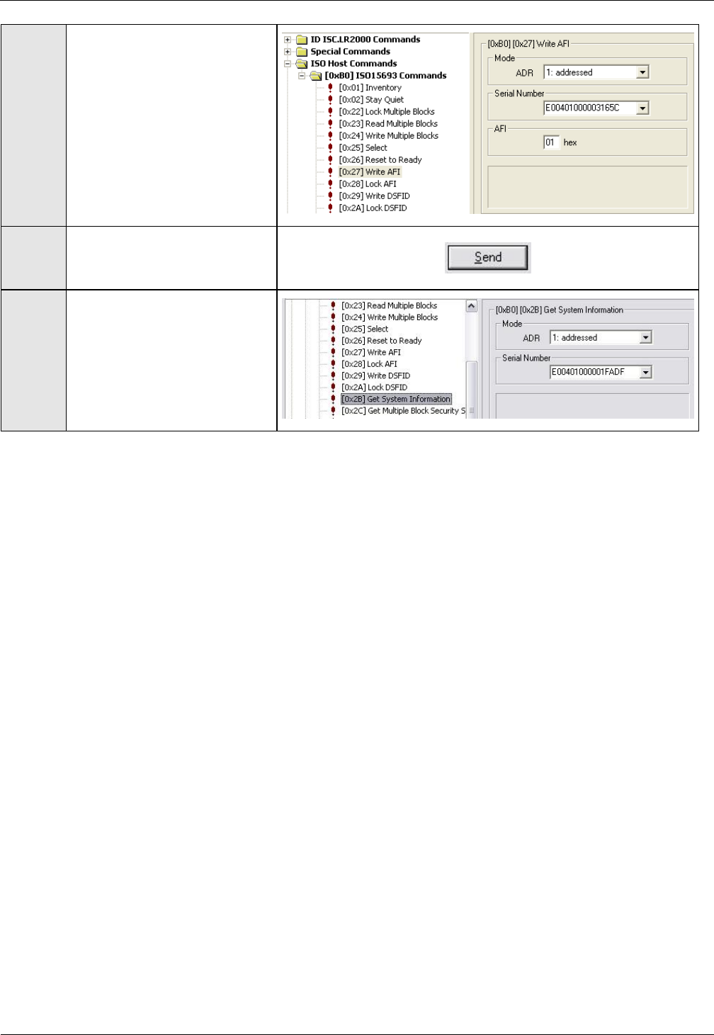
OBID i-scan® HF
Installation
ID ISC.ANT1300/680-A/-B/-BL
FEIG ELECTRONIC GmbH
Seite 37 von 47
M71104-9e-ID-B.doc
5
Select „[0x27] Write AFI“
ADR:
1: addressed
Serial Number:
Select Transponder UID
AFI:
Desired AFI Number (not
equal to 00)
6
Write AFI byte on to the
transponder by click on
„Send“
7
To verify, read AFI byte by
using the command
[0x2B] Get System
Information
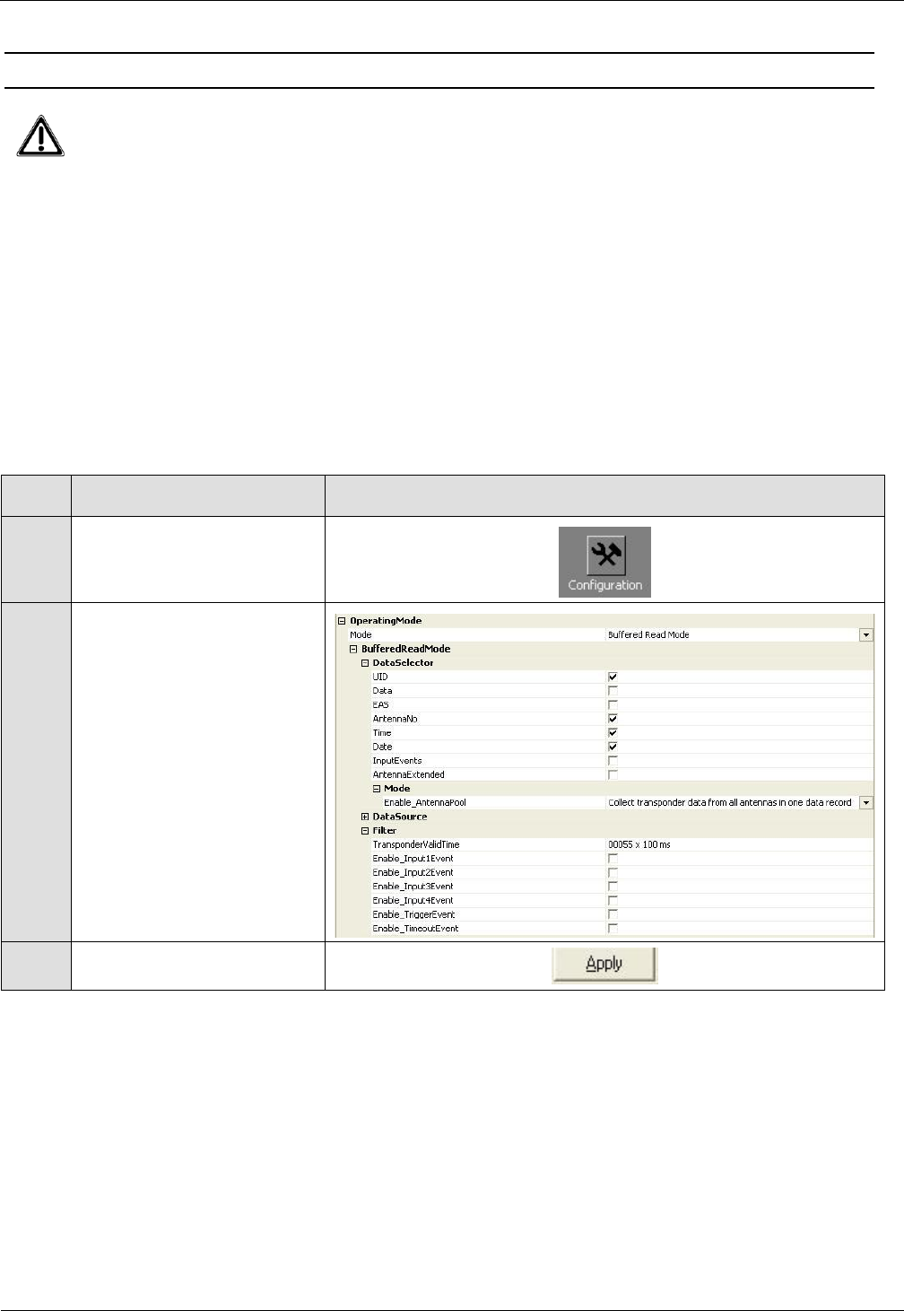
OBID i-scan® HF
Installation
ID ISC.ANT1300/680-A/-B/-BL
FEIG ELECTRONIC GmbH
Seite 38 von 47
M71104-9e-ID-B.doc
4.5 Activating the Automatic Mode
The gate has to be used in one of the Automatic Modes (Buffered Read, Notification
or Scan Mode) to get a maximum performance. Otherwise the reading speed will be
significantly reduced.
For more information, see System Manual H20411-xe-ID-B.pdf ID ISC.LRM1002
Which mode the most suitable is for your application has to be defined in advance.
In this example it is described how to activate the Buffered Read Mode.
In the automatic modes, the tags are read at maximum speed and the information is stored in the
ring buffer of the reader. This Data set can be read by the host.
Due to the automatic alarm features at the automatic mode, the reader/gate can also run without
any interface connection (Serial, Ethernet).
To activate „Buffered Read Mode“ proceed as follows:
Step
Action
Note
1
Select „Configuration“
2
Operation Mode:
„Mode“ - Buffered Read
Mode
„Data Selector“
-UID
-Antenna No
-Time
-Date
„Filter“
Set Transponder Valid
Time.
(e.g. 55 x 100ms)
3
Set clicking on „Apply“
Note:
The configuration of the Notification or Scan Mode are similar (See System Manual of the reader)
To test the function of the Gate in the Buffered Read Mode, the BRM Window of ISOStart or the
BRMDemo program can be used.

OBID i-scan® HF
Installation
ID ISC.ANT1300/680-A/-B/-BL
FEIG ELECTRONIC GmbH
Seite 39 von 47
M71104-9e-ID-B.doc
4.6 Configuring the Reader in accordance with national RF regulations
Configuration of the RFID Readers and the maximum transmitting power of the antennas are
affected mainly by the country-specific RF regulations. For the entire EU the limits are set forth in
the R&TTE Directive and EN 300 330. In North America this is regulated by FCC Part 15 (USA)
and by the RSS-210 (Canada).
The ID ISC.ANT1300/680 antenna with the ID ISC.LRM1002 Reader, when used as intended,
complies with the basic requirements of Article 3 and the other relevant clauses of the R&TTE
Directive 1999/5/EG of March 99. This means that operation in the 29 EU countries and the EFTA
countries (EU countries plus Switzerland, Norway and Iceland) is possible with a maximum field
strength of 42 dBµA/m at 10 m distance.
RF approval (at a maximum field strength of 42 dBµA/m at 10 m) for the ID ISC.ANT1300/680
antenna with ID ISC.LRM1002 Reader has been granted in accordance with FCC Part 15 for the
USA and the RSS-210 for Canada
RF approval in accordance with EN 300 330 is still possible in all 46 CEPT countries.
The CEPT countries are:
Albania (ALB), Andorra (AND), Austria (AUT), Azerbaijan (AZE), Belarus (BLR), Belgium (BEL),
Bulgaria (BUL), Bosnia and Herzegovina (BIH), Croatia (HRV), Cyprus (CYP), Czech Republic
(CZE), Denmark (DNK), Estonia (EST), Finland (FIN), France (F), Germany (D), Greece (GRC),
Hungary (HNG), Iceland (ISL), Ireland (IRL), Italy (I), Latvia (LVA), Liechtenstein (LIE), Lithuania
(LTU), Luxembourg (LUX), Malta (MLT), Former Yugoslav Republic of Macedonia (MKD), Moldova
(MDA), Monaco (MCO), Netherlands (HOL), Norway (NOR), Poland (POL), Portugal (POR),
Romania (ROU), Russian Federation (RUS), San Marino (SMR), Slovak Republic (SVK), Slovenia
(SVN), Spain (E), Sweden (S), Switzerland (SUI), Turkey (TUR), Ukraine (UKR), United Kingdom
(G), Vatican City (CVA) and Yugoslavia.
The following restrictions are in effect (as of: October 2009):
1. Outside the EFTA countries RF approval must in all cases be applied for. The existing
measuring protocols in accordance with EN 300 330 are generally sufficient.
When placing the antennas in service, the systems integrator must ensure that the prescribed
mounting instructions are followed, the necessary Reader settings are made and permissible limits
according to the national regulations are not exceeded.

OBID i-scan® HF
Installation
ID ISC.ANT1300/680-A/-B/-BL
FEIG ELECTRONIC GmbH
Seite 40 von 47
M71104-9e-ID-B.doc
The Reader needs to be configured as follows depending on the installation location:
Parameter
USA / Canada / Europe
Air Interface
RF-Power:
maximum 5 W
RF Modulation:
15%
Transponder
RF Modulation / ISO-MODE /
MOD
10%
RF Data coding ISO-MODE:
Fast (1/4)
Timeslots ISO-MODE / NO-TS
1 or 16 Timeslots
ISO Option – BREAK:
Complete Timeslot length at
„NO TAG“

OBID i-scan® HF
Installation
ID ISC.ANT1300/680-A/-B/-BL
FEIG ELECTRONIC GmbH
Seite 41 von 47
M71104-9e-ID-B.doc
5 Technical Data
5.1 Antenna ID ISC.ANT1300/680 - Type A and Type B
Mechanical Data
Housing
UV stabilized ABS
Dimensions ( W x H x D )
– Antenna
– Packing
720 mm x 1590 mm x 80 mm 3 mm
800 mm x 1720 mm x 160 mm 10 mm
Weight
– ID ISC.ANT1300/680-A
– ID ISC.ANT1300/680-B/-BL
Approx. 16 kg without / 21 kg with packing
Approx. 15 kg without / 20 kg with packing
Enclosure rating
IP 43
Color
Antenna frame: light grey RAL 7035
Antenna base: signal black RAL 9004
Mounting
– No. of attaching points
– Recommended anchors
– Recommended minimum load
capacity of the floor fastener
2
10 mm
5000 N / anchor
Maximum horizontal load on the top
edge of the antenna
250 N*
Electrical Data****
Supply Voltage
24 V 15 %
Noise Ripple : max. 150 mV
Power Consumption
max. 32 VA
Operating Frequency
13,56 MHz
Transmit Power
2 W to 5 W
(250 mW Step - Software)
Maximum transmitting power per
antenna
5 W

OBID i-scan® HF
Installation
ID ISC.ANT1300/680-A/-B/-BL
FEIG ELECTRONIC GmbH
Seite 42 von 47
M71104-9e-ID-B.doc
Permissible overall transmitting
power per antenna gate
– EU-territory (per EN 300 330) and
other CEPT nations
– USA (lt. FCC Part 15)
– Canada (lt. RSS210)
maximal 5,0 W
maximal 5,0 W
maximal 5,0 W
Outputs
– 1 Relay ( 1 x Changeover)
24 V / 1 A for Alarm Kit
Inputs
– 1 Optocoupler
Max. 24 V / 20 mA
Interfaces
RS232
Ethernet (TCP/IP)
Protocol Modes
FEIG ISO HOST
BRM (Data Filtering and Data Buffering)
Notification Mode (TCP/IP)
Supported Transponders
ISO 15693, ISO 18000-3-A, (EM HF ISO
Chips, Fujitsu HF ISO Chips, KSW Sensor
Chips, Infineon my-d, NXP I-Code , STM ISO
Chips, TI Tag-it)
NXP I-Code 1
Ranges / pass-through width in gate
with power splitter
– One tag orientation
– All tag orientations
approx. 120 cm**
approx. 90 cm***
Antenna connection
1 x SMA plug (50 )
Antenna connector cable
Type B
RG58, 50 , approx. 2 m long

OBID i-scan® HF
Installation
ID ISC.ANT1300/680-A/-B/-BL
FEIG ELECTRONIC GmbH
Seite 43 von 47
M71104-9e-ID-B.doc
Ambient Conditions
Temperature range
– Operating
– Storage
–25 °C to +50 °C
–25 °C to +70 °C
Applicable Standards
RF approval
– Europe
– USA
- Canada
EN 300 330
FCC Part 15
RSS 210
EMC
EN 301 489
Safety
– Low Voltage Directive
– Human Exposure
UL 60950-1
EN 50364
* Persistent deformation after load release approx. 1 cm.
** Qty. 2 ID ISC.ANT1300/680-A/-B antennas, antenna spacing (antenna center), same flow
direction, Tag 46 mm x 75 mm ISO15693, sensitivity / minimum field strength Hmin=60 mA/m rms,
transmitting power 5 W, tag orientation parallel to antenna for horizontal movement through the
antenna. The detection performance also depending of the strength of the Transponder answer
signal !
*** Tag 46 mm x 75 mm ISO 15693, sensitivity / minimum field strength Hmin=60 mA/m rms,
transmitting power 5 W, aligned in all 3 dimensions for horizontal movement through the antenna.
The detection performance also depending of the strength of the Transponder answer signal !

OBID i-scan® HF
Installation
ID ISC.ANT1300/680-A/-B/-BL
FEIG ELECTRONIC GmbH
Seite 44 von 47
M71104-9e-ID-B.doc
5.2 Approval
As per Section 4.6 Fehler! Verweisquelle konnte nicht gefunden werden.!
5.2.1 Europe (CE)
This RF equipment is in compliance with the essential requirements and other relevant provisions
of Directive 1999/5/EC dated March 99.
Equipment Classification according to ETSI EN 300 330 and ETSI EN 301 489: Class 2
The technical data of the ID ISC.LRM1002 Reader module built into the ID ISC.ANT1300/680-
A antenna can be found in the Installation Manual which is included with the device.

OBID i-scan® HF
Installation
ID ISC.ANT1300/680-A/-B/-BL
FEIG ELECTRONIC GmbH
Seite 45 von 47
M71104-9e-ID-B.doc
5.2.2 USA (FCC) and Canada (IC)
Product name:
ID ISC.ANT1300/680
Antenna name:
ID ISC.ANT1300/680 Type A
Reader name:
ID ISC.LRM1002
FCC ID:
IC:
PJMLRM1002
6633A-LRM1002
Notice for USA and
Canada
This device complies with Part 15 of the FCC Rules and with
RSS-210 of Industry Canada.
Operation is subject to the following two conditions.
(1) this device may not cause harmful interference, and
(2) this device must accept any interference received,
including interference that may cause undesired operation.
Unauthorized modifications may void the authority granted under
Federal communications Commission Rules permitting the operation
of this device.
This equipment has been tested and found to comply with the limits for
a Class A digital device, pursuant to Part 15 of the FCC Rules. These
limits are designed to provide reasonable protection against harmful
interference when the equipment is operated in a commercial
environment. This equipment generates, uses, and can radiate radio
frequency energy and, if not installed and used in accordance with the
instruction manual, may cause harmful interference to radio
communications. Operation of this equipment in a residential area is
likely to cause harmful interference in which case the user will be
required to correct the interference at his own expense.
Le présent appareil est conforme aux CNR d'Industrie Canada appli-
cables aux appareils radio exempts de licence. L'exploitation est auto-
risée aux deux conditions suivantes :
(1) l'appareil ne doit pas produire de brouillage, et
(2) l'utilisateur de l'appareil doit accepter tout brouillage radioélectrique
subi, même si le brouillage est susceptible d'en compromettre le fonc-
tionnement.
Further information and technical data of the ID ISC.LRM1002 Reader module built into the
ID ISC.ANT1300/680 antenna can be found in the Installation Manual which is included with
the device.

OBID i-scan® HF
Installation
ID ISC.ANT1300/680-A/-B/-BL
FEIG ELECTRONIC GmbH
Seite 46 von 47
M71104-9e-ID-B.doc
6 Annex A
6.1 Terminal assignment “Terminal Board”
Terminal
Acronym
Description
X1 / LR
24V DC Reader
X1 / Pin 1
+24 V DC Reader
X1 / Pin 2
GND
GND Reader
X2 / I/O
24V DC Input/Output
X2 / Pin 1
+24 V DC Input/Output
X2 / Pin 2
GND
GND Input/Output
X3 / MUX
24V DC Multiplexer/Power Splitter (optional)
X3 / Pin 1
+24 V DC Multiplexer
X3 / Pin 2
GND
GND Multiplexer
X4 / TRG
Trigger Input (optional)
X4 / Pin 1
+
TRG Trigger
X4 / Pin 2
-
GND Trigger
X6 / LED1
Connection LED / Alarm LED 1. Antenna
X14 / Pin 1
+
+24V DC LED1
X14 / Pin 2
-
GND LED1
X11
24V DC Power Supply
X11 / Pin 1
24V
Power Supply +24 V DC
X11 / Pin 2
- / GND
Ground – Power Supply
X12 / LED2
Connection LED / Alarm LED 2. Antenna
X12 / Pin 1
+
+ 24 V DC LED2
X12 / Pin 2
-
GND LED2
X14 / LED3
Connection LED / Alarm LED 3. Antenna
X14 / Pin 1
+
+24V DC LED3
X14 / Pin 2
-
GND LED3
Table 9: Pin-Configuration X1-X14 Terminal Board

OBID i-scan® HF
Installation
ID ISC.ANT1300/680-A/-B/-BL
FEIG ELECTRONIC GmbH
Seite 47 von 47
M71104-9e-ID-B.doc
6.2 Sources of supply measuring instruments and accessories
1. SWR Meter, Antennen Analyzer
Diamond VSWR & Power – Meter KW220, SX -600 or SX1100
Supplier:
WiMo Antennen und Zubehör : + 49 7276-96680, www.wimo.de
Conrad Electroinc : www.conrad.de
MFJ HF/UHF SWR Analyzer
Model MFJ-259B, 1.8 – 170 MHz
Supplier:
WiMo Antennen und Zubehör : Tel.: +49 7276-96680, www.wimo.de
MFJ Enterprises, Inc : Tel.: +1-800-647-1800, http://www.mfjenterprises.com
VIA or CIA – HF Complex Impedance Analyzer 5012 – 5000
Supplier:
Heinz Bollig AG Nachrichtentechnik, Tel.: + 41 71 335 0723, www.hbag.ch
TransmitteRus, Phone.: +44 (0)7971-053067, www.transmitterus.com
AEA Technology Inc., +1-800-258-7805, http://www.aeatechnology.com
2. Adapter : SMA/PL, 50 Ohm dummy load, koaxiale cable with connector
Supplier:
WiMo Antennen und Zubehör : Tel.: + 49 7276-96680, www.wimo.de
Conrad Electroinc : www.conrad.de
Farnell GmbH www.farnell.com
Digi-Key Corporation, www.digikey.com