Feig Electronic LRM1002 ID ISC.LRM1002 wth ID ISC.ANT.Mux and ID ISC.ANT800/600-DA User Manual Testreport ETS 300 335
Feig Electronic GmbH ID ISC.LRM1002 wth ID ISC.ANT.Mux and ID ISC.ANT800/600-DA Testreport ETS 300 335
Contents
- 1. user manual
- 2. User manual
- 3. Users Manual
User manual

Test report no. 17011006 Page 1 of 1
EUT: ID ISC.LRM1002 with
ID ISC.ANT.Mux and ID
ISC.ANT800/600-DA
FCC ID:
PJMLRM1002
FCC Title 47 CFR Part 15
Date of issue: 2017-10-02
Date: 2017-09-07
Created: P9 Controlled: P4 Released: P1
Vers. no. 1.17
m. dudde hochfrequenz-technik
GmbH & Co. KG
Rottland 5a
51429 Bergisch Gladbach/ Germany
Tel: +49 2207-96890
Fax +49 2207-968920
Annex acc. to FCC Title 47 CFR Part 15
relating to
FEIG ELECTRONIC GmbH
ID ISC.LRM1002 with
ID ISC.ANT.Mux and
ID ISC.ANT800/600-DA
Annex no. 5
User Manual
Functional Description
Title 47 - Telecommunication
Part 15 - Radio Frequency Devices
Subpart C – Intentional Radiators
ANSI C63.4-2014
ANSI C63.10-2013
INTEGRATIONSANLEITUNG
final – public (B)
2014-05-14 – M21110-2d-ID-B.docx
ID ISC.LRM1002-E
Long Range Reader Modul
(Deutsch)

OBID i-scan® HF
Integration
ID ISC.LRM1002-E
FEIG ELECTRONIC GmbH
Seite 2 von 24
M21110-2d-ID-B.docx
Hinweis
Copyright 2012-2014 by
FEIG ELECTRONIC GmbH
Lange Straße 4
D-35781 Weilburg
Tel.: +49 6471 3109-0
http://www.feig.de
Alle früheren Ausgaben verlieren mit dieser Ausgabe ihre Gültigkeit.
Die Angaben in diesem Dokument können ohne vorherige Ankündigung geändert werden.
Weitergabe sowie Vervielfältigung dieses Dokuments, Verwertung und Mitteilung ihres Inhalts sind nicht
gestattet, soweit nicht ausdrücklich zugestanden. Zuwiderhandlung verpflichtet zu Schadenersatz. Alle
Rechte für den Fall der Patenterteilung oder Gebrauchsmuster-Eintragung vorbehalten.
Die Zusammenstellung der Informationen in diesem Dokument erfolgt nach bestem Wissen und Gewissen.
FEIG ELECTRONIC GmbH übernimmt keine Gewährleistung für die Richtigkeit und Vollständigkeit der An-
gaben in diesem Dokument. Insbesondere kann FEIG ELECTRONIC GmbH nicht für Folgeschäden auf
Grund fehlerhafter oder unvollständiger Angaben haftbar gemacht werden. Da sich Fehler, trotz aller Bemü-
hungen nie vollständig vermeiden lassen, sind wir für Hinweise jederzeit dankbar.
Die in diesem Dokument gemachten Installationsempfehlungen gehen von günstigsten Rahmenbedingun-
gen aus. FEIG ELECTRONIC GmbH übernimmt weder Gewähr für die einwandfreie Funktion in system-
fremden Umgebungen, noch für die Funktion eines Gesamtsystems, welches die in diesem Dokument be-
schriebenen Geräte enthält.
FEIG ELECTRONIC weist ausdrücklich darauf hin, dass die in diesem Dokument beschriebenen Geräte
nicht für den Einsatz mit oder in medizinischen Geräten oder für Geräte für lebenserhaltende Maßnahmen
konzipiert sind, bei denen ein Fehler eine Gefahr für menschliches Leben oder für die gesundheitliche Un-
versehrtheit zur Folge haben kann. Der Applikationsdesigner ist dafür verantwortlich geeignete Maßnahmen
zu ergreifen um Gefahren, Schäden oder Verletzungen zu vermeiden.
FEIG ELECTRONIC GmbH übernimmt keine Gewährleistung dafür, dass die in diesem Dokument enthal-
tenden Informationen frei von fremden Schutzrechten sind. FEIG ELECTRONIC GmbH erteilt mit diesem
Dokument keine Lizenzen auf eigene oder fremde Patente oder andere Schutzrechte.
OBID® und OBID i-scan® ist ein eingetragenes Warenzeichen der FEIG ELECTRONIC GmbH

OBID i-scan® HF
Integration
ID ISC.LRM1002-E
FEIG ELECTRONIC GmbH
Seite 3 von 24
M21110-2d-ID-B.docx
Content
1 Sicherheits- und Warnhinweise - vor Inbetriebnahme unbedingt lesen 4
2 Leistungsmerkmale der Reader ID ISC.LR1002-E 5
2.1 Leistungsmerkmale .................................................................................................... 5
2.2 Verfügbare Readervarianten ...................................................................................... 5
3 Montage und Anschluss 6
3.1 Montage ID ISC.LRM1002-E ....................................................................................... 6
3.2 Anschlussklemmen .................................................................................................... 8
3.2.1 Antennenanschluss .................................................................................................. 9
3.2.1.1 Anschluss eines ID ISC.DAT (Dynamic Antenna Tuning Board) ................... 10
3.2.2 Versorgungsspannung ........................................................................................... 11
3.2.3 Optokoppler Eingang (X5 / IN1) ............................................................................. 12
3.2.4 Relais (X6 / REL1) ................................................................................................. 14
3.2.5 Ausgang 24V (X5 / VIN, GND)......................................................................... 15
3.3 Schnittstellen ............................................................................................................ 16
3.3.1 RS232-Schnittstelle X4 .......................................................................................... 16
3.3.2 USB – Schnittstelle X11 (Host Kommunikation) ..................................................... 17
3.3.3 Ethernet-Schnittstelle an X3 (10/100 Base-T) ........................................................ 18
4 Bedien- und Anzeigeelemente 19
4.1 LEDs .......................................................................................................................... 19
5 Funkzulassungen 20
5.1 Europa (CE) ............................................................................................................... 20
5.2 USA (FCC) und Kanada (IC) ..................................................................................... 21
5.3 Label Information Reader ID ISC.LR1002-E ............................................................ 22
5.3.1 USA (FCC) and Canada (IC) approved antennas ................................................... 22
6 Technische Daten 23

OBID i-scan® HF
Integration
ID ISC.LRM1002-E
FEIG ELECTRONIC GmbH
Seite 4 von 24
M21110-2d-ID-B.docx
1 Sicherheits- und Warnhinweise - vor Inbetriebnahme unbedingt lesen
Das Gerät darf nur für den vom Hersteller vorgesehenen Zweck verwendet werden.
Die Bedienungsanleitung ist zugriffsfähig aufzubewahren und jedem Benutzer auszuhändigen.
Unzulässige Veränderungen und die Verwendung von Ersatzteilen und Zusatzeinrichtungen,
die nicht vom Hersteller des Gerätes verkauft oder empfohlen werden, können Brände, elektri-
sche Schläge und Verletzungen verursachen. Solche Maßnahmen führen daher zu einem
Ausschluss der Haftung und der Hersteller übernimmt keine Gewährleistung.
Für das Gerät gelten die Gewährleistungsbestimmungen des Herstellers in der zum Zeitpunkt
des Kaufs gültigen Fassung. Für eine ungeeignete, falsche manuelle oder automatische Ein-
stellung von Parametern für ein Gerät bzw. ungeeignete Verwendung eines Gerätes wird keine
Haftung übernommen.
Reparaturen dürfen nur vom Hersteller durchgeführt werden.
Anschluss-, Inbetriebnahme-, Wartungs-, und sonstige Arbeiten am Gerät dürfen nur von Elekt-
rofachkräften mit einschlägiger Ausbildung erfolgen.
Alle Arbeiten am Gerät und dessen Aufstellung müssen in Übereinstimmung mit den nationa-
len elektrischen Bestimmungen und den örtlichen Vorschriften durchgeführt werden.
Beim Arbeiten an dem Gerät müssen die jeweils gültigen Sicherheitsvorschriften beachtet wer-
den.
Vor Berührung der Platinen ist stets die Spannungsversorgung abzuschalten und durch Nach-
messen sicherzustellen, dass das Gerät spannungslos ist. Das Verlöschen einer Betriebsan-
zeige ist kein Indikator dafür, dass das Gerät vom Netz getrennt und spannungslos ist.
Besonderer Hinweis für Träger von Herzschrittmachern:
Obwohl dieses Gerät die zulässigen Grenzwerte für elektromagnetische Felder nicht über-
schreitet, sollten Sie einen Mindestabstand von 25 cm zwischen der angeschlossenen Antenne
und Ihrem Herzschrittmacher einhalten und sich nicht für längere Zeit in unmittelbarer Nähe
des Geräts bzw. der Antenne aufhalten.

OBID i-scan® HF
Integration
ID ISC.LRM1002-E
FEIG ELECTRONIC GmbH
Seite 5 von 24
M21110-2d-ID-B.docx
2 Leistungsmerkmale der Reader ID ISC.LR1002-E
2.1 Leistungsmerkmale
Der Reader ist für das Lesen von passiven Datenträgern, sogenannten „Smart Labels“, mit einer
Betriebsfrequenz von 13,56 MHz entwickelt. Zum Betrieb ist es notwendig eine geeignete externe
Antenne an dem Anschluss „ANT1“ anzuschließen.
2.2 Verfügbare Readervarianten
Folgende Readervarianten sind z.Z. verfügbar:
Reader
Beschreibung
ID ISC.LRM1002-E
Modulvariante mit RS232 / USB / LAN-Interface
ID ISC.LR1002-E
Gehäusevariante mit RS232 / USB / LAN-Interface
Tabelle 1: Verfügbare Readervarianten
OBID i-scan® HF
Integration
ID ISC.LRM1002-E
FEIG ELECTRONIC GmbH
Seite 6 von 24
M21110-2d-ID-B.docx
3 Montage und Anschluss
3.1 Montage ID ISC.LRM1002-E
Das Reader-Modul ist für die Montage auf einem Kühlkörper konzipiert. Für die Befestigung befin-
det sich in den vier Ecken der Trägerplatte jeweils eine Bohrung mit dem 4,5 mm (siehe Abbil-
dung 1)
120
110
ø 4,5 mm*
160
155
80
ø 4,5 mm* ø 4,5 mm*
5
ø 4,5 mm
155
ø 4,5 mm
5
4
29
V3 V2 V1
V4
NO
NC
COM
TxD
RxD
GND
GND
VIN
GND
VIN
IN -
IN +
X1 X5
X4
X6
X11
X3
ANT1
Abbildung 1 Maßzeichnung des Reader-Moduls mit Montageplatte

OBID i-scan® HF
Integration
ID ISC.LRM1002-E
FEIG ELECTRONIC GmbH
Seite 7 von 24
M21110-2d-ID-B.docx
Für die Ausnutzung der vollen Leistungsfähigkeit des Reader-Moduls sollte der verwendete Kühl-
körper einen Wärmewiderstand RThK von maximal 2,0 K/W besitzen. Bei der Montage des Reader-
Moduls auf den Kühlkörper ist auf einen möglichst geringen Wärmeübergangswiderstand zwischen
Trägerplatte und Kühlkörper zu achten. Die Verwendung von Wärmeleitpaste wird empfohlen.
Bei korrekt abgestimmter Antenne und ausreichender Luftkonvektion entlang der Montageplatte
kann der ID ISC.LRM1002-E auch ohne zusätzlichen Kühlkörper bis zu einer Leistung von 2 W
betrieben werden. Hierbei ist jedoch zu beachten, dass eine Verstimmung der Antenne zu einer
zusätzlichen Erwärmung des Readers führt. In diesem Falle regelt der Reader seine Ausgangsleis-
tung zurück bis die obere Grenztemperatur seiner Endstufe wieder unterschritten wird.
OBID i-scan® HF
Integration
ID ISC.LRM1002-E
FEIG ELECTRONIC GmbH
Seite 9 von 24
M21110-2d-ID-B.docx
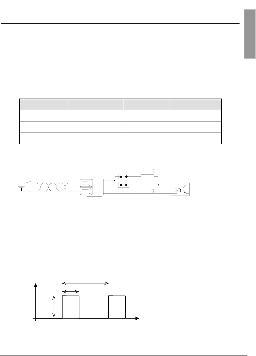
3.2.1 Antennenanschluss
Zum Anschluss der Antenne an den ID ISC.LRM1002 befindet sich auf der Leiterplatte die SMA-
Buchse "ANT1".
Eine externe LED kann zusätzlich über den Antennenanschluss mit 6,5 V versorgt werden.
Diese kann per Software-Konfiguration aktiviert werden. Die maximale Stromaufnahme darf dabei
20mA nicht überschreiten.
Es ist nicht möglich damit das Antennen Tuning Board ID ISC.DAT zu versorgen!
Siehe: Anschluss eines ID ISC.DAT (Dynamic Antenna Tuning Board)
Das maximale Anzugsdrehmoment der SMA-Buchse beträgt 0,45 Nm.
Achtung:
Höhere Anzugsdrehmomente führen zur Zerstörung der Buchse.
Klemme
Beschreibung
ANT1
Anschluss der externen Antenne
(Eingangsimpedanz 50)
Tabelle 2: Anschluss der externen Antenne
Hinweise:
Das Stehwellenverhältnis VSWR der Antenne sollte den Wert 1,3 nicht überschreiten.
Für das Erreichen optimaler Lesereichweiten müssen die Koaxialkabel zwischen
Reader und Antenne definierte Längen haben. Für alle Antennen von der Firma FEIG
ELECTRONIC GmbH und für alle Antennen welche mit den Abgleichplatinen (z.B. ID
ISC.DAT, ID ISC.MAT-B und ID ISC.MAT-S) von FEIG ELECTRONIC GmbH aufgebaut
sind ist die optimale Länge des Koaxialkabels 1,35 m (Artikel Nr. 1654.004.00.00, Be-
zeichnung ID ISC.ANT.C-B). Siehe auch Montageanleitung Power Splitter ID
ISC.ANT.PS-B und ID ISC.ANT.MUX.
Die optimale Betriebsgüte der Antenne sollte im Bereich QB = 10...30 liegen. Zur Er-
mittlung der Betriebsgüte muss die Antenne mit einer 50-Quelle, z.B. einem Net-
work Analyzer oder einem Frequenzgenerator, versorgt werden.
Zur Vermeidung extern eingekoppelter Störungen muss die Antennenzuleitung dem
beigefügten EMV-Ringkernferrit 28 mm x 20 mm versehen werden. Hierzu ist die
Antennenzuleitung mindestens vier mal, eng anliegend durch den EMV-
Ringkernferrit zu führen. Der Abstand zwischen Readeranschluss ANT1 und
Ringkern sollte dabei maximal 10 cm betragen (siehe Abbildung 3).
Beim Anschluss der Antenne ist darauf zu achten, dass diese die zulässigen Grenz-
werte der nationalen Vorschriften bezüglich Funkanlagen nicht überschreitet.
Abbildung 3 Antennenkabel mit EMV-Ringkernferrit
OBID i-scan® HF
Integration
ID ISC.LRM1002-E
FEIG ELECTRONIC GmbH
Seite 10 von 24
M21110-2d-ID-B.docx
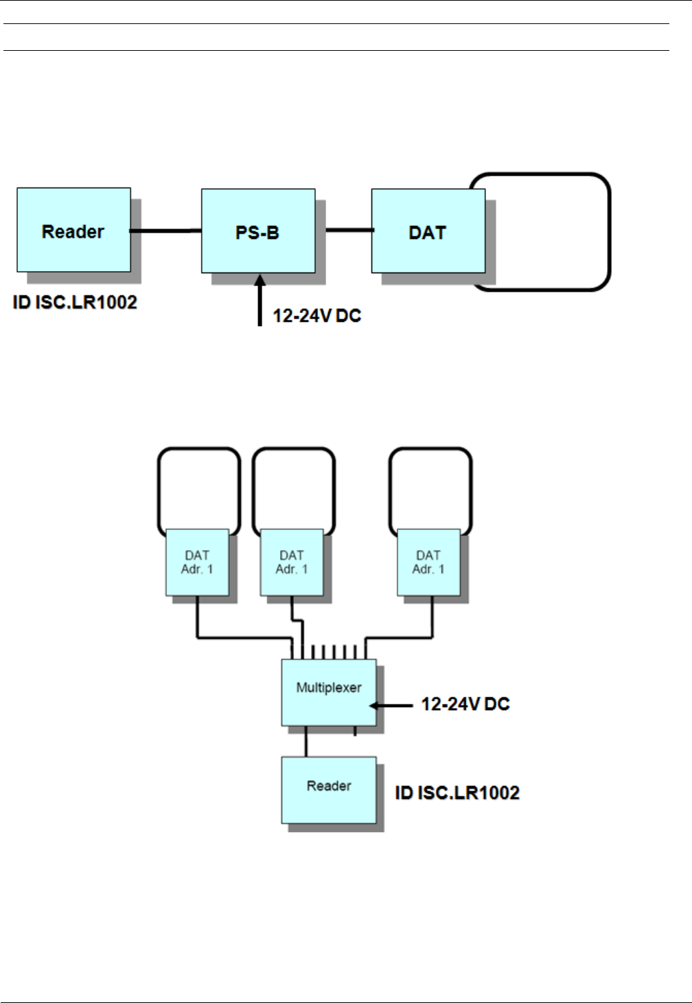
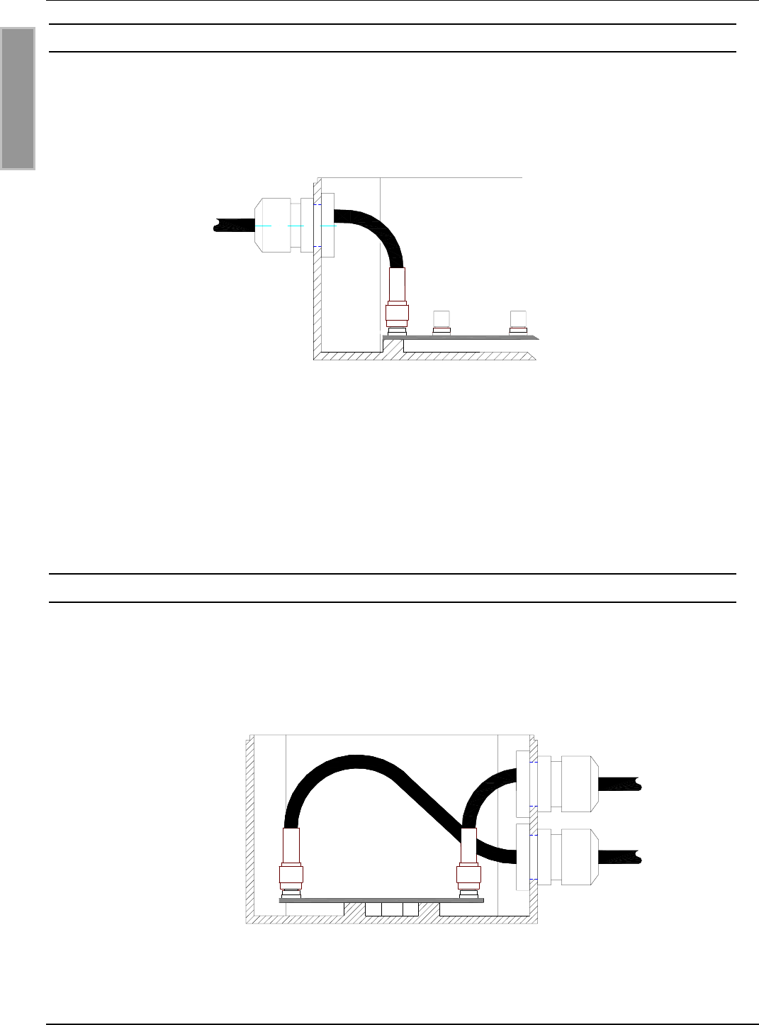
3.2.1.1 Anschluss eines ID ISC.DAT (Dynamic Antenna Tuning Board)
Um Antennen mit einem ID ISC.DAT Tuning Board zu betreiben wird zum tunen eine DC Span-
nung benötigt. Diese DC Spannung muss über einen Powersplitter (ID ISC.ANT.PS-B) oder einem
Antennen Multiplexer (ID ISC.ANT.MUX) zur Verfügung gestellt werden.
Abbildung 4 zeigt die DC Spannungsversorgung des ID ISC.DAT mit einem Powersplitter.
Abbildung 4: DC Spannungsversorgung des ID ISC.DAT mit einem ID ISC.ANT-PS-B
Abbildung 5 zeigt die DC Spannungsversorgung des ID ISC.DAT mit einem Antennen Multiplexer.
Abbildung 5: DC Spannungsversorgung des ID ISC.DAT mit einem ID ISC.ANT.MUX.
OBID i-scan® HF
Integration
ID ISC.LRM1002-E
FEIG ELECTRONIC GmbH
Seite 11 von 24
M21110-2d-ID-B.docx
3.2.2 Versorgungsspannung
Der Reader darf nur von einer Spannungsversorgung gemäß EN 60950-1 Kapitel 2.5 Stromquel-
len begrenzter Leistung (LPS) oder mit einen nach NEC Class 2/LPS zertifizierten Netzteil versorgt
werden.
Die Versorgungsspannung von 24 V ist an der Klemme X1 anzuschließen.
Klemme
Kurzzeichen
Beschreibung
X1
VIN
Vcc – Versorgungsspannung +24 V DC /
X1
GND
Ground – Versorgungsspannung
Tabelle 3: Pinbelegung Versorgungsspannung
GND
VIN
X1 X5
Abbildung 6: Position der Klemme X1 für die Versorgungsspannung
Hinweis:
Eine Verpolung der Versorgungsspannung kann zur Zerstörung des Gerätes führen.
Zur Reduzierung von Störungen (Noise) kann die Versorgungsspannungszuleitung
mit einem EMV-Ringkernferrit 28 mm x 20 mm versehen werden. Hierzu ist das
Kabel mindestens fünf mal, eng anliegend durch den EMV-Ringkernferrit zu schlei-
fen. Der Abstand zwischen Readeranschluss und Ringkern sollte dabei maximal 10
cm betragen.
OBID i-scan® HF
Integration
ID ISC.LRM1002-E
FEIG ELECTRONIC GmbH
Seite 12 von 24
M21110-2d-ID-B.docx
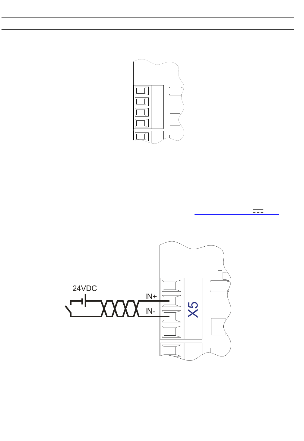
3.2.3 Optokoppler Eingang (X5 / IN1)
Der Optokoppler Eingang ist auf dem Klemmleiste X5 zugänglich.
GND
VIN
IN -
IN +
X5
Abbildung 7: Digitaler Eingang an der Klemmleiste X5
Der Optokoppler an der Klemmleiste X5 ist galvanisch von der Reader-Elektronik getrennt und
muss daher mit einer externen 24 VDC Spannung versorgt werden.
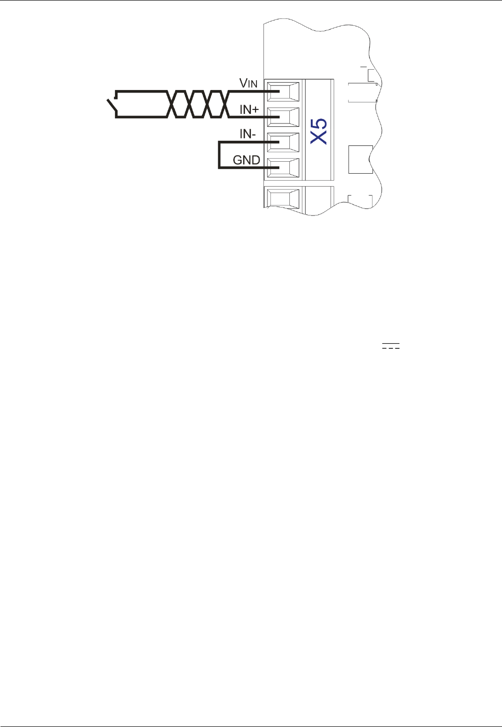
Die externe VCC Spannung kann jedoch auch über die Anschlüsse VIN (24VDC) und GND
(Ground) von dem Reader zur Verfügung gestellt werden. Siehe: 3.2.5 Ausgang 24V (X5 /
VIN, GND)
Abbildung 8: Mögliche externe Spannungsversorgung der Optokoppler am Anschluss X5
OBID i-scan® HF
Integration
ID ISC.LRM1002-E
FEIG ELECTRONIC GmbH
Seite 13 von 24
M21110-2d-ID-B.docx
Abbildung 9: Mögliche interne Spannungsversorgung der Optokoppler am Anschluss X5
Die Eingangs-LED des Optokopplers ist intern mit einem Serienwiderstand von 3,74 k beschaltet
um den Eingangsstrom auf max. 6 mA zu begrenzen.
Hinweise:
Der Eingang ist für eine maximale Eingangsspannung von 24 V und einem Ein-
gangsstrom von maximal 6 mA ausgelegt.
Verpolung oder Überlastung des Eingangs kann zu dessen Zerstörung führen.
Die gleichzeitige Verwendung der internen und einer externen Versorgungsspan-
nung kann zur Zerstörung des Gerätes führen.
OBID i-scan® HF
Integration
ID ISC.LRM1002-E
FEIG ELECTRONIC GmbH
Seite 14 von 24
M21110-2d-ID-B.docx
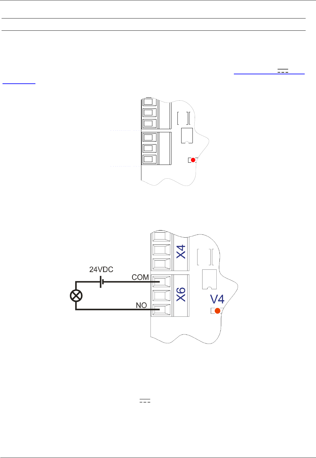
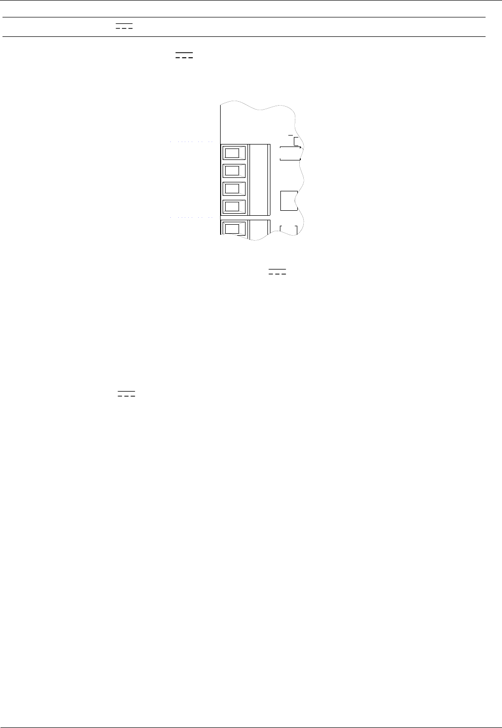
3.2.4 Relais (X6 / REL1)
Als Relaisausgang stehen ein Wechsler zur Verfügung. Die jeweiligen Kontakte stehen an den
Klemme X6 zur Verfügung. Die Ausgänge sind galvanisch von der Reader-Elektronik getrennt und
müssen daher mit einer externen Spannung versorgt werden. Die externe Spannung kann auch
von dem Anschluss X5 VIN und GND zur Verfügung gestellt werden. Siehe: Ausgang 24V (X5 /
VIN, GND)
V4
NO
NC
COM
X4
X6
Abbildung 10: Relais Ausgänge an der Klemmleiste X6
Abbildung 11: Mögliche externe Beschaltung der Relaisausgänge mit
externer Spannungsversorgung
Hinweise:
Der Relaisausgang ist für max. 24 V / 1 A ausgelegt.
Der Relaisausgang ist nur zum Schalten ohmscher Lasten vorgesehen. Im Falle einer
induktiven Last sind die Relaiskontakte durch eine externe Schutzbeschaltung zu
schützen.
Die gleichzeitige Verwendung der internen und einer externen Versorgungsspannung
kann zur Zerstörung des Gerätes führen.
OBID i-scan® HF
Integration
ID ISC.LRM1002-E
FEIG ELECTRONIC GmbH
Seite 15 von 24
M21110-2d-ID-B.docx
3.2.5 Ausgang 24V (X5 / VIN, GND)
Am Ausgang VIN/GND stehen 24V für die externe Spannungsversorgung des digitalen Ein-
gangs sowie des Relais zur Verfügung. Die maximale Stromentnahme darf 1A nicht überschreiten.
GND
VIN
IN -
IN +
X5
Abbildung 12: Mögliche externe 24V Spannungsversorgung
Hinweise:
Die an diesem Ausgang entnommene Leistung für die externe Beschaltung muss bei
der Dimensionierung des Netzteils zusätzlich zu der typischen Reader Leistung mit
berücksichtigt werden.
Die interne 24V Versorgungsspannung an X5 ist nicht über eine Sicherung abge-
sichert.
OBID i-scan® HF
Integration
ID ISC.LRM1002-E
FEIG ELECTRONIC GmbH
Seite 16 von 24
M21110-2d-ID-B.docx
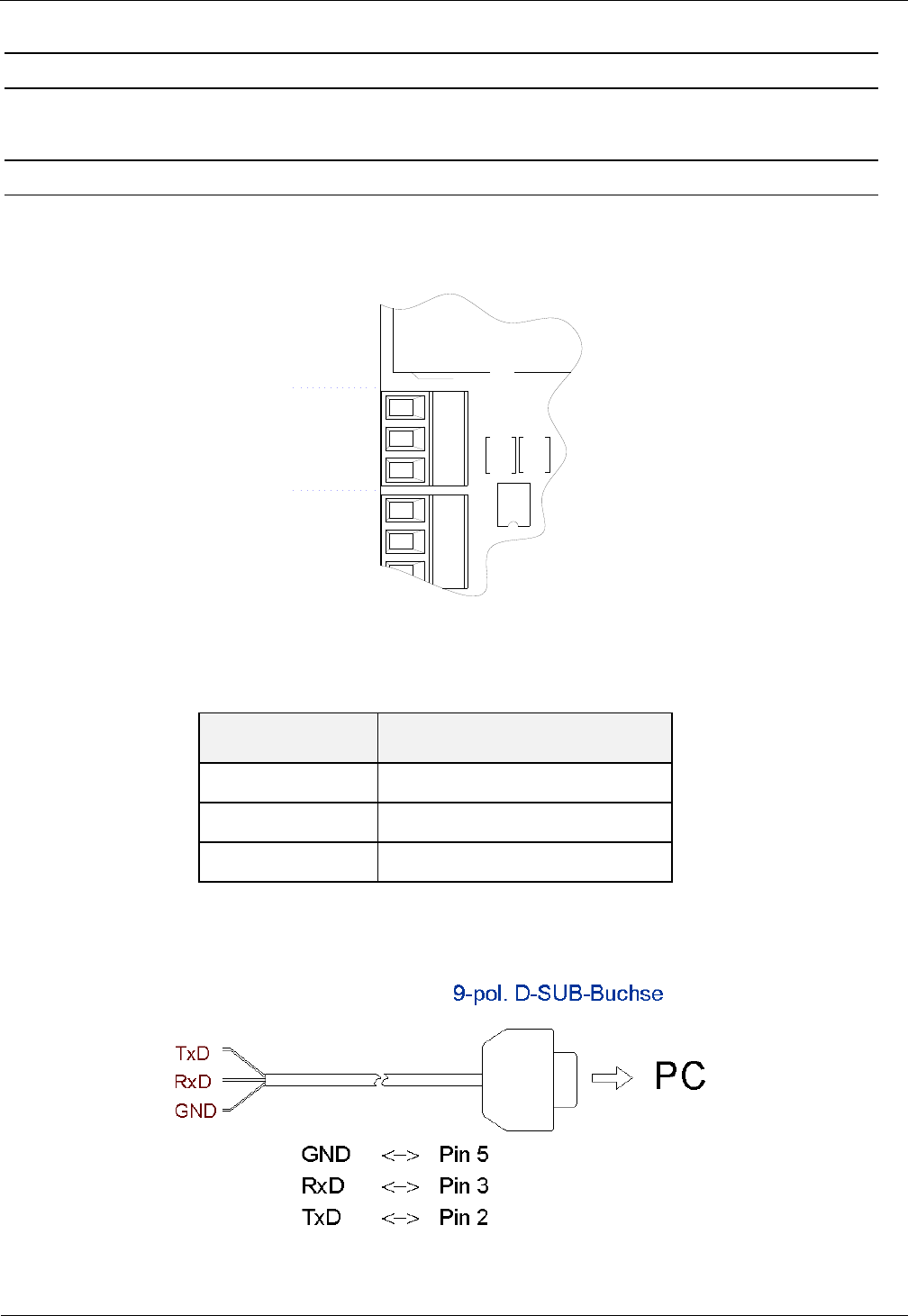
3.3 Schnittstellen
3.3.1 RS232-Schnittstelle X4
Der Anschluss der RS232-Schnittstelle erfolgt über X4. Die Übertragungsparameter können per
Softwareprotokoll konfiguriert werden.
TxD
RxD
GND
X4
X6
Abbildung 13: Anschlussbelegung X4 (RS232-Schnittstelle)
Kurzzeichen
Beschreibung
TxD
RS232 – (Transmit)
RxD
RS232 – (Receive)
GND
RS232 – (Ground)
Tabelle 4 Belegung RS232-Schnittstelle
Abbildung 14: Verdrahtungsbeispiel für den Anschluss der RS232-Schnittstelle
OBID i-scan® HF
Integration
ID ISC.LRM1002-E
FEIG ELECTRONIC GmbH
Seite 17 von 24
M21110-2d-ID-B.docx
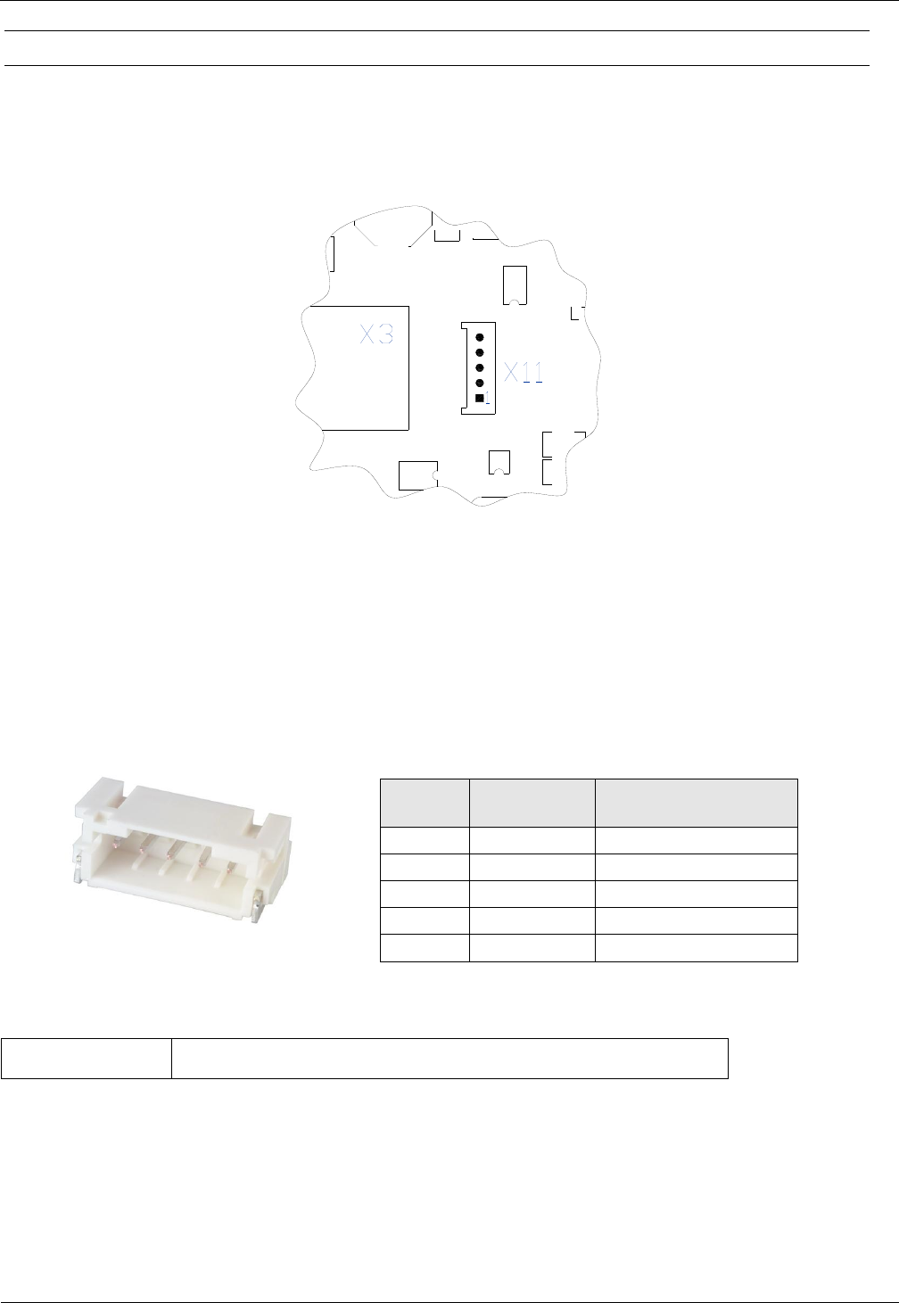
3.3.2 USB – Schnittstelle X11 (Host Kommunikation)
Der Anschluss der USB-Schnittstelle erfolgt über Buchse X11. Die Datenrate des Readers ist auf
12 Mbit beschränkt (USB Full Speed).
Nachfolgende Abbildung 16 und Tabelle zeigt die Belegung der Stecker X11 (5pol.) vom Typ “JST
PH” RM 2 mm (stehend).
X2
Pin-Nr.
1
Schirm
USB Kabel - Schirm
2
GND
3
USB-D PLUS
4
USB-D MINUS
5
VCC
+ 5 V DC 5 %
Optional kann folgendes USB-Anschlusskabel verwendet werden:
3541.000.00
ID CAB.USB-B Cable for Interface USB/JST PH
Hinweis:
Die maximale Länge des USB-Kabels darf 5 m betragen. Längere Kabel sind nicht erlaubt.
Abbildung 15: USB-Schnittstelle für Host Kommunikation an X11
Abbildung 16 Stecker „JST PH“
OBID i-scan® HF
Integration
ID ISC.LRM1002-E
FEIG ELECTRONIC GmbH
Seite 18 von 24
M21110-2d-ID-B.docx
3.3.3 Ethernet-Schnittstelle an X3 (10/100 Base-T)
Der Reader verfügt über eine integrierte 10/100 Base-T Netzwerkschnittstelle mit Standard RJ-45-
Anschluss. Der Anschluss erfolgt über X3 und hat eine automatische „Crossover Detection“ ent-
sprechend dem 1000 Base-T Standard.
Bei einer strukturierten Verkabelung sollten mindestens Kabel der Kategorie CAT5 verwendet wer-
den. Dies garantiert einen problemlosen Betrieb bei 10 Mbps oder 100 Mbps.
Voraussetzung für den Einsatz des TCP/IP-Protokolls ist, dass jedes Gerät am Netzwerk über eine
eigene IP-Adresse verfügt. Alle Reader verfügen über eine werksseitig voreingestellte IP-Adresse.
Netzwerk
Adresse
IP-Adresse
192.168.10.10
Subnet-Mask
255.255.255.0
Port
10001
DHCP
AUS
Tabelle 5: Werkskonfiguration der Ethernet-Schnittstelle
Hinweis:
Der Reader verfügt über eine DHCP-fähige TCP/IP Schnittstelle, die werkseitig aus-
geschaltet ist.
Es wird empfohlen ein abgeschirmtes STP (shielded twisted pair) CAT5 Kabel zu
verwenden.
X3
Abbildung 17: LAN Schnittstelle für Host Kommunikation

OBID i-scan® HF
Integration
ID ISC.LRM1002-E
FEIG ELECTRONIC GmbH
Seite 19 von 24
M21110-2d-ID-B.docx
4 Bedien- und Anzeigeelemente
4.1 LEDs
Tabelle 6 zeigt die Konfiguration der LEDs.
Kurzzeichen
Beschreibung
LED V1 (grün)
"RUN-LED 1"
- Signalisiert den ordnungsgemäßen Ablauf der
internen Reader-Software (DSP)
- Leuchtet während der Reader-Initialisierung nach dem Ein-
schalten bzw. nach einem Reset.
LED V2 (blau)
Diagnose 1: RF-Kommunikation / EEPROM-Status
- Signalisiert durch ein kurzes Blinken die fehlerfreie Kommuni-
kation mit einem Transponder auf der RF-Schnittstelle
- Blinkt abwechselnd mit V1 nach dem Reset im Anschluss an
ein Software-Update
- Blinkt abwechselnd mit V1 falls nach einem Reset ein Daten-
fehler beim Lesen der Parameter auftrat
LED V3 (gelb)
Diagnose 2: Host-Kommunikation
- Signalisiert durch ein kurzes Blinken das Senden eines Proto-
kolls an den Host auf der RS232/USB/LAN-Schnittstelle
LED V4 (rot)
Diagnose 4: RF-Warnung
- Leuchtet bei einem Fehler im RF-Teil des Readers. Der Feh-
lertyp kann per Software über die RS232/USB/LAN-
Schnittstelle ausgelesen werden
Tabelle 6: Konfiguration der LEDs

OBID i-scan® HF
Integration
ID ISC.LRM1002-E
FEIG ELECTRONIC GmbH
Seite 20 von 24
M21110-2d-ID-B.docx
5 Funkzulassungen
5.1 Europa (CE)
Die Funkanlage entspricht, bei bestimmungsgemäßer Verwendung den grundlegenden Anforde-
rungen des Artikels 3 und den übrigen einschlägigen Bestimmungen der R&TTE Richtlinie
1999/5/EG vom März 99.
Equipment Classicfication gemäß ETSI EN 301 489: Class 2 SRD

OBID i-scan® HF
Integration
ID ISC.LRM1002-E
FEIG ELECTRONIC GmbH
Seite 21 von 24
M21110-2d-ID-B.docx
5.2 USA (FCC) und Kanada (IC)
Product name:
ID ISC.LRM1002-E
Reader name:
ID ISC.LRM1002-E
FCC ID:
IC:
PJMLRM1002
6633A-LRM1002
Notice for USA and
Canada
This device complies with Part 15 of the FCC Rules and with
RSS-210 of Industry Canada.
Operation is subject to the following two conditions.
(1) this device may not cause harmful interference, and
(2) this device must accept any interference received,
including interference that may cause undesired operation.
Unauthorized modifications may void the authority granted under
Federal communications Commission Rules permitting the operation
of this device.
This equipment has been tested and found to comply with the limits for
a Class A digital device, pursuant to Part 15 of the FCC Rules. These
limits are designed to provide reasonable protection against harmful
interference when the equipment is operated in a commercial
environment. This equipment generates, uses, and can radiate radio
frequency energy and, if not installed and used in accordance with the
instruction manual, may cause harmful interference to radio
communications. Operation of this equipment in a residential area is
likely to cause harmful interference in which case the user will be
required to correct the interference at his own expense.
Le présent appareil est conforme aux CNR d'Industrie Canada appli-
cables aux appareils radio exempts de licence. L'exploitation est auto-
risée aux deux conditions suivantes :
(1) l'appareil ne doit pas produire de brouillage, et
(2) l'utilisateur de l'appareil doit accepter tout brouillage radioélectrique
subi, même si le brouillage est susceptible d'en compromettre le fonc-
tionnement.
Warning: Changes or modification made to this equipment not expressly approved by
FEIG ELECTRONIC GmbH may void the FCC authorization to operate this equipment.
Installation with FCC / IC Approval:
FCC-/IC-NOTICE: To comply with FCC Part 15 Rules in the United States / with IC Radio Stand-
ards in Canada, the system must be professionally installed to ensure compliance with the Part 15
certification / IC certification. It is the responsibility of the operator and professional installer to en-
sure that only certified systems are deployed in the United States / Canada.

OBID i-scan® HF
Integration
ID ISC.LRM1002-E
FEIG ELECTRONIC GmbH
Seite 22 von 24
M21110-2d-ID-B.docx
5.3 Label Information Reader ID ISC.LRM1002-E
Die folgende Information muss auf dem Gehäuse von außen sichtbar sein:
5.3.1 USA (FCC) and Canada (IC) approved antennas
This radio transmitter (identify the device by certification number, or model number if Category II)
has been approved by Industry Canada to operate with the antenna types listed below with maxi-
mum permission gain and required antenna impedance for each antenna type indicated. Antenna
types, not included in this list, having a gain greater than the maximum gain indicated for that type,
are strictly prohibited for use with this device
Le présent émetteur radio (identifier le dispositif par son numéro de certification ou son numéro de
modèle s’il fait partie du matériel de catégorie I) a été approuvé par Industrie Canada pour fonc-
tionner avec les types d’antenne ’énoncé ci-dessus et ayant un gain admissible maximal et
l’impédance requise pour chaque type d’antenne. Les types d’antenne non inclus dans cette liste,
ou dont le gain est supérieur au gain maximal indiqué, sont strictement interdits pour l’exploitation
de l’émetteur
Following antennas are approved by FCC according FCC Part 15 and IC Canada according
RS210
ID ISC.ANT310/310-A (magnetic antenna)
ID ISC.ANTS370/270-A (magnetic antenna)
ID ISC.ANT1300/680-A (magnetic antenna)

OBID i-scan® HF
Integration
ID ISC.LRM1002-E
FEIG ELECTRONIC GmbH
Seite 23 von 24
M21110-2d-ID-B.docx
6 Technische Daten
Mechanische Daten
Abmessungen ( B x H x T )
160 x 120 x 35 mm³
Gewicht
Approx. 0,35 kg
Elektrische Daten
Spannungsversorgung
24 V 15 %
Noise Ripple : max. 150 mV
Leistungsaufnahme
max. 16 VA
Betriebsfrequenz
13,56 MHz
Sendeleistung
1 W – 5 W
(per Software in 1 W Schritten einstellbar)
Modulationsgrad
14%
Antennenanschluss
SMA Buchse (50 , SWR ≤1.3)
Gleichspannung auf
der Antennenleitung
6,5 V (max. 20mA)
Diagnoseoptionen
Interne Impedanzüberwachung
interne Temperaturüberwachung
Ausgänge
– 1 Relais (NO)
24 V / 1A
Eingänge
– 1 Optokoppler
24 V / 6 mA
Schnittstellen
- RS232
- USB
- Ethernet (TCP/IP)
Protokoll Modi
- FEIG ISO HOST
- BRM (Datenfilterung und Datenpufferung)
- Scan Mode
- Notification Mode

OBID i-scan® HF
Integration
ID ISC.LRM1002-E
FEIG ELECTRONIC GmbH
Seite 24 von 24
M21110-2d-ID-B.docx
Unterstützte Transponder
ISO15693, ISO18000-3 MODE 1
(EM HF ISO Chips, Fujitsu HF ISO Chips,
KSW Sensor Chips, IDS Sensor Chips
Infineon my-d, NXP I-Code, STM ISO Chips,
TI Tag-it)
ISO18000-3M3 (Upgrade Code required)
Signalgeber, optisch
4 LEDs zur Diagnose des Betriebszustandes
Umgebungsbedingungen
Temperaturbereich
– Betrieb
– Lagerung
-20°C bis +55°C
-25°C bis +85°C
Luftfeuchtigkeit
5% - 80%, nicht kondensierend
Vibration
EN60068-2-6
10 Hz bis 150 Hz : 0,075 mm / 1 g
Schock
EN60068-2-27
Beschleunigung : 30 g
Zulassung
Zulassung Funk
– Europa
– USA
EN 300 330
FCC 47 CFR Part 15
EMV
EN 301 489
Sicherheit
– Elektrische Sicherheit
– Human Exposure
EN 60950
EN 50364
MONTAGE
INSTALLATION
final
public (B)
2003-10-28
M30201-1de-ID-B.doc
OBID i-scan
®
ID ISC.ANT.MUX
Antenna Multiplexer
(deutsch / english)


OBID i-scanMontage ID ISC.ANT.MUX
FEIG ELECTRONIC GmbH Seite 3 von 37 M30201-1de-ID-B.doc
D E U T S C H
Hinweis
Copyright 2003 by
FEIG ELECTRONIC GmbH
Lange Straße 4
D-35781 Weilburg-Waldhausen
Tel.: +49 6471 3109-0
http://www.feig.de
Alle früheren Ausgaben verlieren mit dieser Ausgabe ihre Gültigkeit.
Die Angaben in diesem Dokument können ohne vorherige Ankündigung geändert werden.
Weitergabe sowie Vervielfältigung dieses Dokuments, Verwertung und Mitteilung ihres Inhalts sind nicht
gestattet, soweit nicht ausdrücklich zugestanden. Zuwiderhandlung verpflichtet zu Schadenersatz. Alle
Rechte für den Fall der Patenterteilung oder Gebrauchsmuster-Eintragung vorbehalten.
Die Zusammenstellung der Informationen in diesem Dokument erfolgt nach bestem Wissen und Gewissen.
FEIG ELECTRONIC GmbH übernimmt keine Gewährleistung für die Richtigkeit und Vollständigkeit der An-
gaben in diesem Dokument. Insbesondere kann FEIG ELECTRONIC GmbH nicht für Folgeschäden auf
Grund fehlerhafter oder unvollständiger Angaben haftbar gemacht werden. Da sich Fehler, trotz aller Bemü-
hungen nie vollständig vermeiden lassen, sind wir für Hinweise jederzeit dankbar.
Die in diesem Dokument gemachten Installationsempfehlungen gehen von günstigsten Rahmenbedingun-
gen aus. FEIG ELECTRONIC GmbH übernimmt keine Gewähr für die einwandfreie Funktion in systemfrem-
den Umgebungen.
FEIG ELECTRONIC GmbH übernimmt keine Gewährleistung dafür, dass die in diesem Dokument enthal-
tenden Informationen frei von fremden Schutzrechten sind. FEIG ELECTRONIC GmbH erteilt mit diesem
Dokument keine Lizenzen auf eigene oder fremde Patente oder andere Schutzrechte.
OBID i-scan ist ein eingetragenes Warenzeichen der FEIG ELECTRONIC GmbH
Das Zeichen „)“ weist auf Erweiterungen bzw. Änderungen gegenüber der Vorgängerversion hin.

OBID i-scanMontage ID ISC.ANT.MUX
FEIG ELECTRONIC GmbH Seite 4 von 37 M30201-1de-ID-B.doc
D E U T S C H
Inhalt
1. Sicherheits- und Warnhinweise - vor Inbetriebnahme unbedingt lesen 5
2. Leistungsmerkmale des 8fach Antennenmultiplexers ID ISC.ANT.MUX 6
2.1. Leistungsmerkmale.......................................................................................................... 6
2.2. Lieferumfang..................................................................................................................... 6
3. Anschluss und Montage 7
3.1. Montage des Gehäuses.................................................................................................... 7
3.2. Anschlussklemmen und Anschlussbuchsen ................................................................. 8
3.3. X1: Spannungsversorgung.............................................................................................. 8
3.4. X2: Eingang (Optokoppler) .............................................................................................. 9
3.5. IN1-2: Readeranschluss ................................................................................................. 10
3.6. OUT1-8: Antennenanschluss......................................................................................... 10
4. Bedien- und Anzeigeelemente 11
4.1. LEDs................................................................................................................................ 11
4.2. DIP-Schalter S1............................................................................................................... 12
4.2.1. Einstellen der Modi.................................................................................................... 12
4.2.2. Adresseinstellung im HF-Communikation Control Mode ........................................... 12
4.2.3. Einstellung Single- oder Dual-Mode im Extern-Trigger Mode .................................... 13
4.2.4. Einstellung Anzahl Ausgänge im Extern-Trigger Mode.............................................. 13
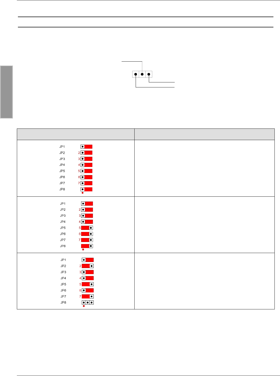
4.3. Jumper JP1- 8................................................................................................................. 14
4.4. Jumper JP11 – JP18....................................................................................................... 15
4.5. Jumper JP19 und JP20 ................................................................................................. 15
5. Inbetriebnahme 16
5.1. HF-Communikation Control Mode................................................................................. 16
5.2. Extern-Trigger Mode ...................................................................................................... 17
ANHANG A: Technische Daten 18

OBID i-scanMontage ID ISC.ANT.MUX
FEIG ELECTRONIC GmbH Seite 5 von 37 M30201-1de-ID-B.doc
D E U T S C H
1. Sicherheits- und Warnhinweise - vor Inbetriebnahme unbedingt lesen
• Das Gerät darf nur für den vom Hersteller vorgesehenen Zweck verwendet werden.
• Die Bedienungsanleitung ist zugriffsfähig aufzubewahren und jedem Benutzer auszuhändigen.
• Unzulässige Veränderungen und die Verwendung von Ersatzteilen und Zusatzeinrichtungen,
die nicht vom Hersteller des Gerätes verkauft oder empfohlen werden, können Brände, elektri-
sche Schläge und Verletzungen verursachen. Solche Maßnahmen führen daher zu einem
Ausschluss der Haftung und der Hersteller übernimmt keine Gewährleistung.
• Für das Gerät gelten die Gewährleistungsbestimmungen des Herstellers in der zum Zeitpunkt
des Kaufs gültigen Fassung. Für eine ungeeignete, falsche manuelle oder automatische Ein-
stellung von Parametern für ein Gerät bzw. ungeeignete Verwendung eines Gerätes wird kei-
ne Haftung übernommen.
• Reparaturen dürfen nur vom Hersteller durchgeführt werden.
• Anschluss-, Inbetriebnahme-, Wartungs-, und sonstige Arbeiten am Gerät dürfen nur von E-
lektrofachkräften mit einschlägiger Ausbildung erfolgen.
• Vor dem Öffnen des Gerätes ist stets die Versorgungsspannung abzuschalten und durch
Nachmessen sicherzustellen, daß das Gerät spannungslos ist. Das Verlöschen einer Be-
triebsanzeige ist kein Indikator dafür, daß das Gerät vom Netz getrennt und spannungslos ist.
• Alle Arbeiten am Gerät und dessen Aufstellung müssen in Übereinstimmung mit den nationa-
len elektrischen Bestimmungen und den örtlichen Vorschriften durchgeführt werden.

OBID i-scanMontage ID ISC.ANT.MUX
FEIG ELECTRONIC GmbH Seite 6 von 37 M30201-1de-ID-B.doc
D E U T S C H
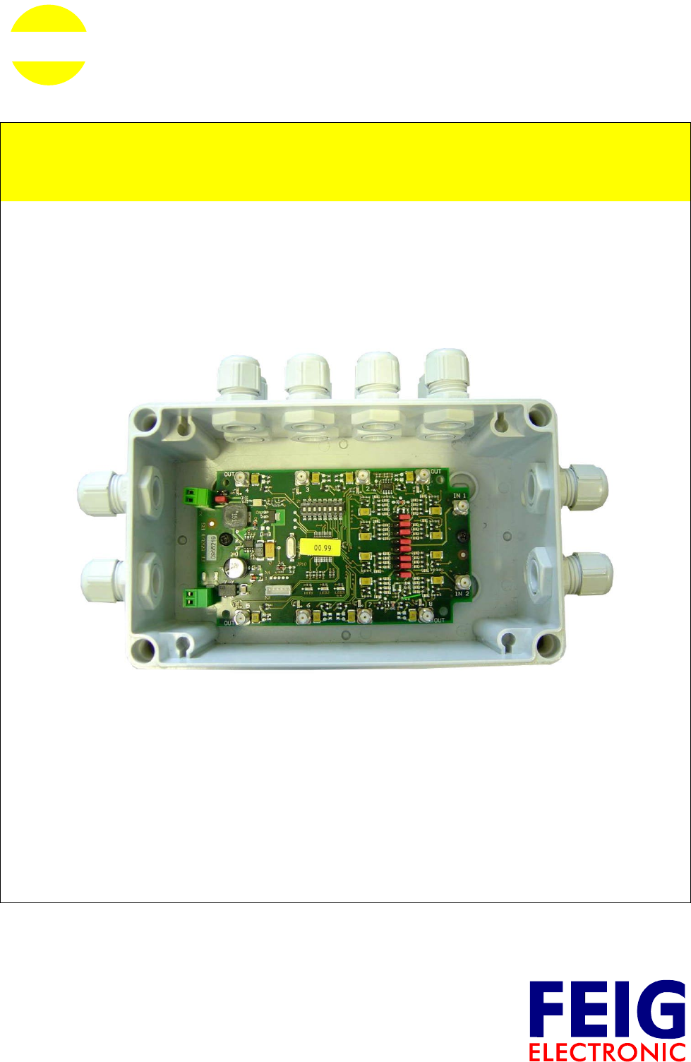
2. Leistungsmerkmale des 8fach Antennenmultiplexers ID ISC.ANT.MUX
2.1. Leistungsmerkmale
Der 8-fach Antennenmultiplexer ID ISC.ANT.MUX eignet sich zum Schalten von RFID Antennen
mit einer Betriebsfrequenz von 13,56 MHz. Mit einem ID ISC.ANT.MUX können mehrere
Einzelantennen (Basisantennen) oder Gateantennen (Basis- und Ergänzungsantennen) mit nur
einem Reader betrieben werden. Alle acht Ausgänge des Antennenmultiplexers können über
Jumpereinstellungen jedem der beiden Eingänge zugeordnet werden.
Es ist möglich, mehrere ID ISC.ANT.MUX zu kaskadieren und so die Anzahl der möglichen
Antennenanschlüsse zu erhöhen. Dazu können die Antennenmultiplexer über DIP-
Schalterstellungen adressiert werden.
2.2. Lieferumfang
Folgende Komponenten sind im Lieferumfang enthalten:
y 8-fach Antennenmultiplexer ID ISC.ANT.MUX
y 8 x Dichtverschluss für M16 Kabelverschraubung
y Montageanleitung
OBID i-scanMontage ID ISC.ANT.MUX
FEIG ELECTRONIC GmbH Seite 7 von 37 M30201-1de-ID-B.doc
D E U T S C H
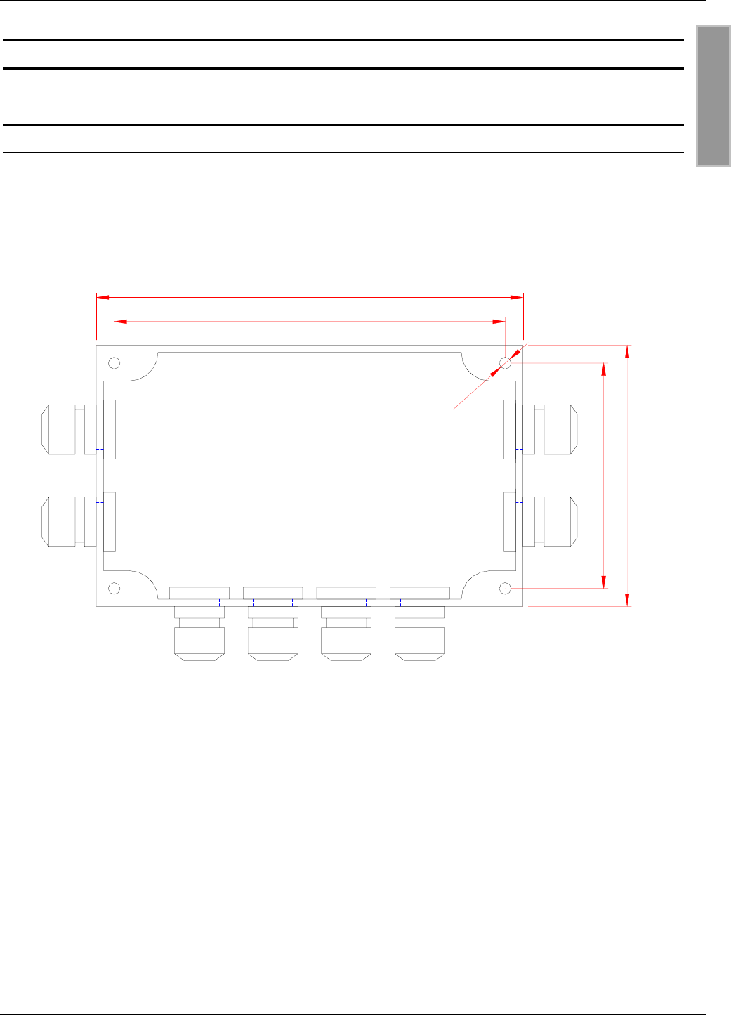
3. Anschluss und Montage
3.1. Montage des Gehäuses
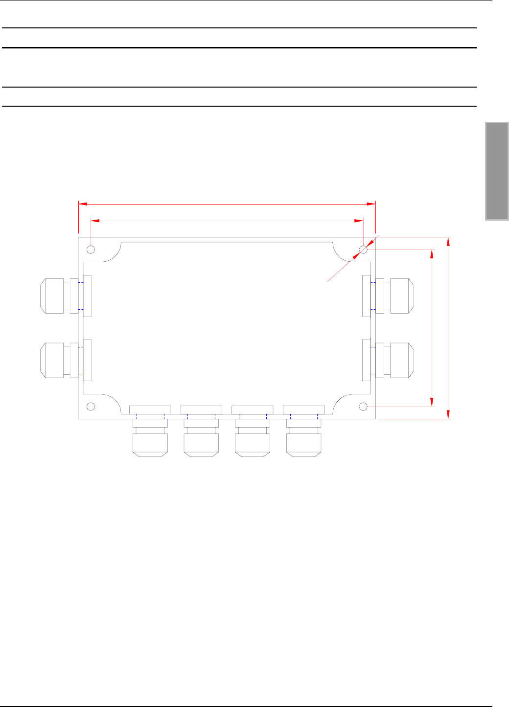
Der Antennenmultiplexer ist für die Montage auf Wänden, auch im Freien, konzipiert. Zur Wand-
befestigung befinden sich in den Ecken des Gehäuses entsprechende Durchbrüche (siehe Bild 1).
Bild 1: Masse und Befestigungsbohrungen
Die Kabeldurchführungen sind M16 x 1,5 Kabelverschraubungen für einen Klemmbereich von
4,5 mm bis 10 mm.
180
165
95
110
4 x ø5
OBID i-scanMontage ID ISC.ANT.MUX
FEIG ELECTRONIC GmbH Seite 8 von 37 M30201-1de-ID-B.doc
D E U T S C H
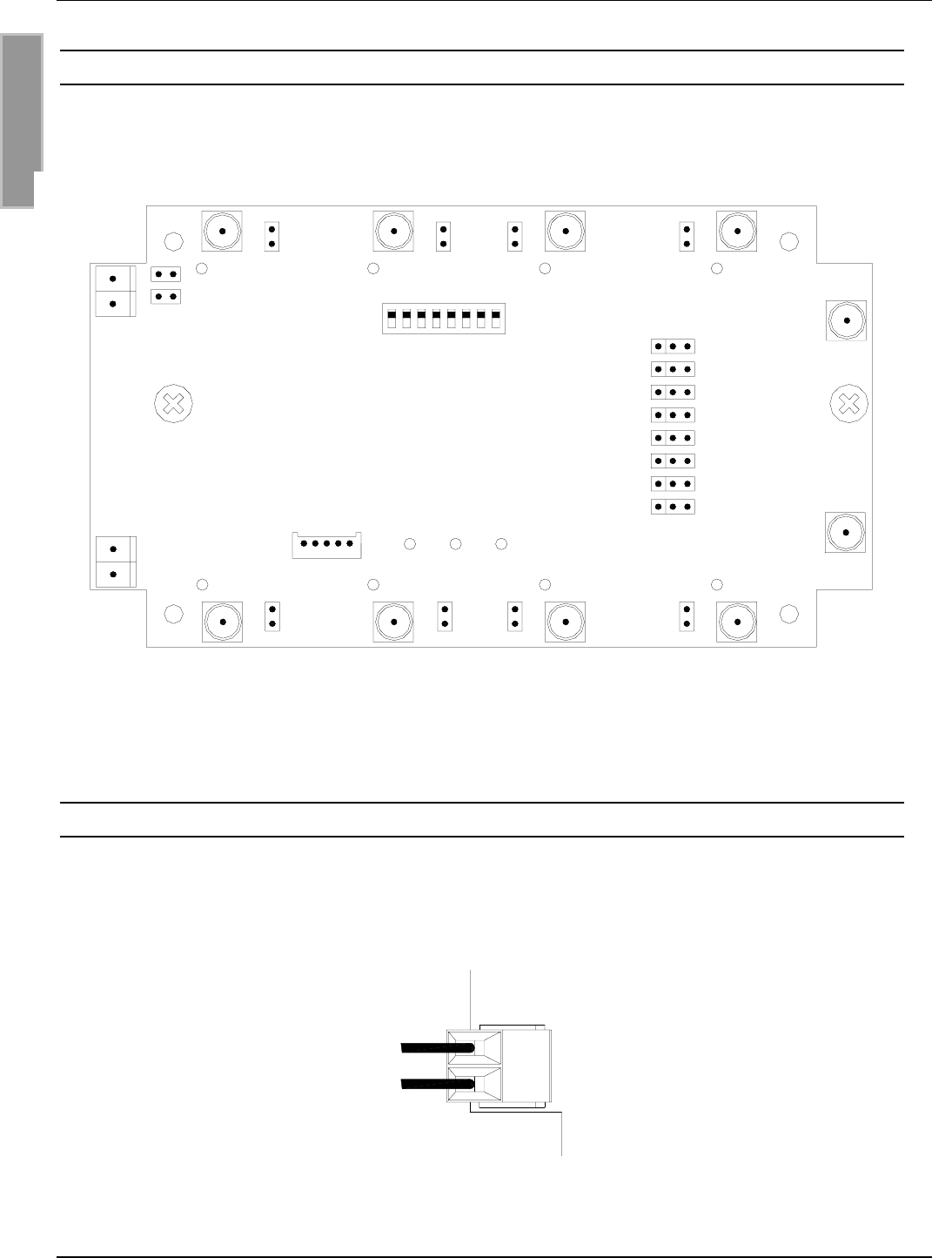
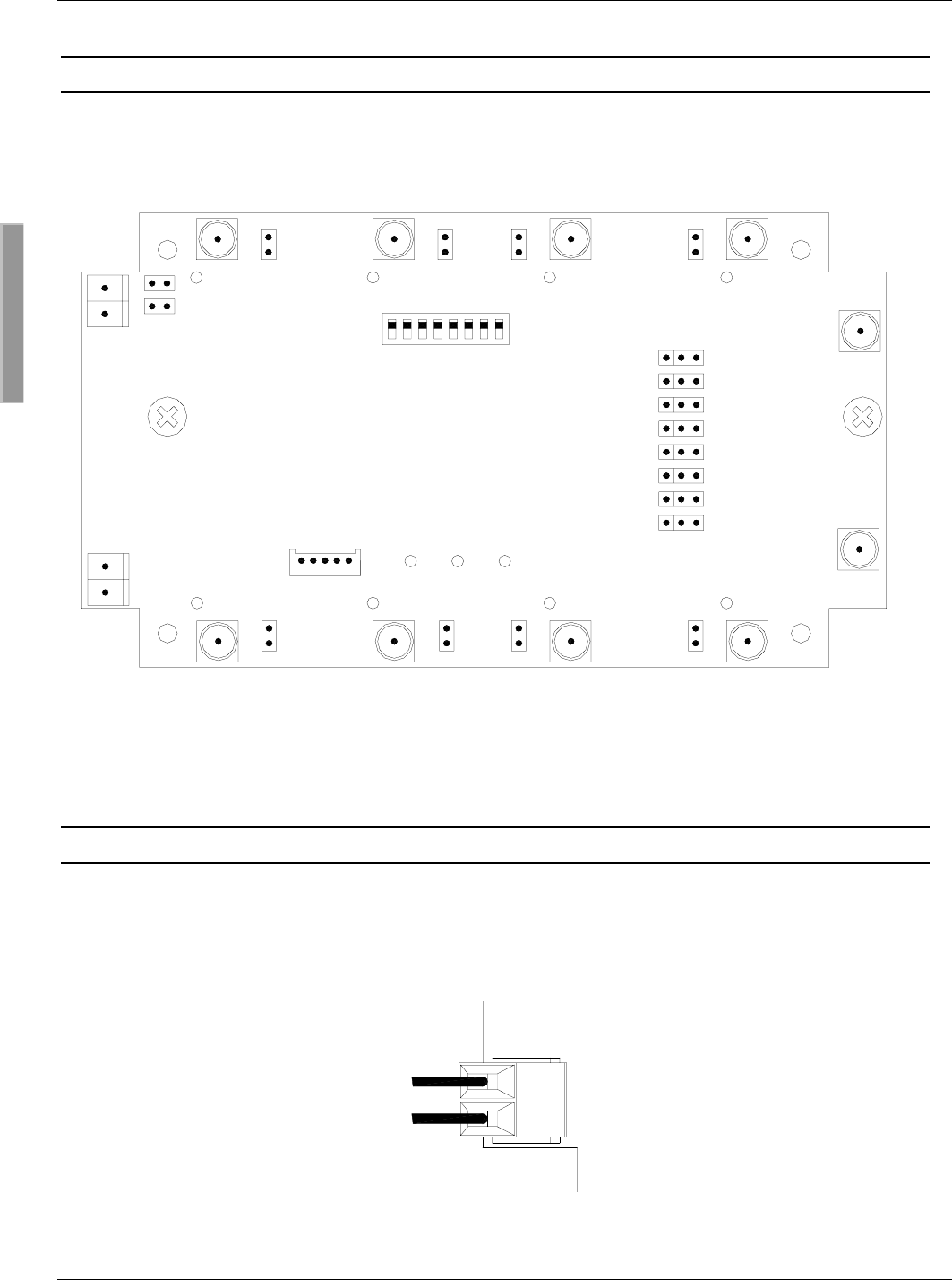
3.2. Anschlussklemmen und Anschlussbuchsen
In Bild 2 sind alle Anschlussklemmen, Buchsen, Bedienteile und Anzeigeteile dargestellt.
Bild 2: Anschlussklemmen, Buchsen und Bedienelemente
3.3. X1: Spannungsversorgung
Die Spannungsversorgung wird über X1 angeschlossen. Dabei ist die Polung gemäß Bild 3 anzu-
klemmen. Der Antennenmultiplexer arbeitet bei einer Gleichspannung von 12V bis 24V.
Bild 3: Anschluss Versorgungsspannung
X1
12-24V DC
GND
JP15 JP16 JP17 JP18
JP14 JP13 JP12 JP11
12345678
ON
OFF IN 1
IN 2
OUT 1OUT 2OUT 3OUT 4
OUT 8OUT 7OUT 6OUT 5
S1
JP1
JP2
JP3
JP4
JP5
JP6
JP7
JP8
JP20
JP19
X1
X2
X3
LED1 LED2 LED3
LEDout5 LEDout6 LEDout7 LEDout8
LEDout1LEDout2LEDout3LEDout4
OBID i-scanMontage ID ISC.ANT.MUX
FEIG ELECTRONIC GmbH Seite 9 von 37 M30201-1de-ID-B.doc
D E U T S C H
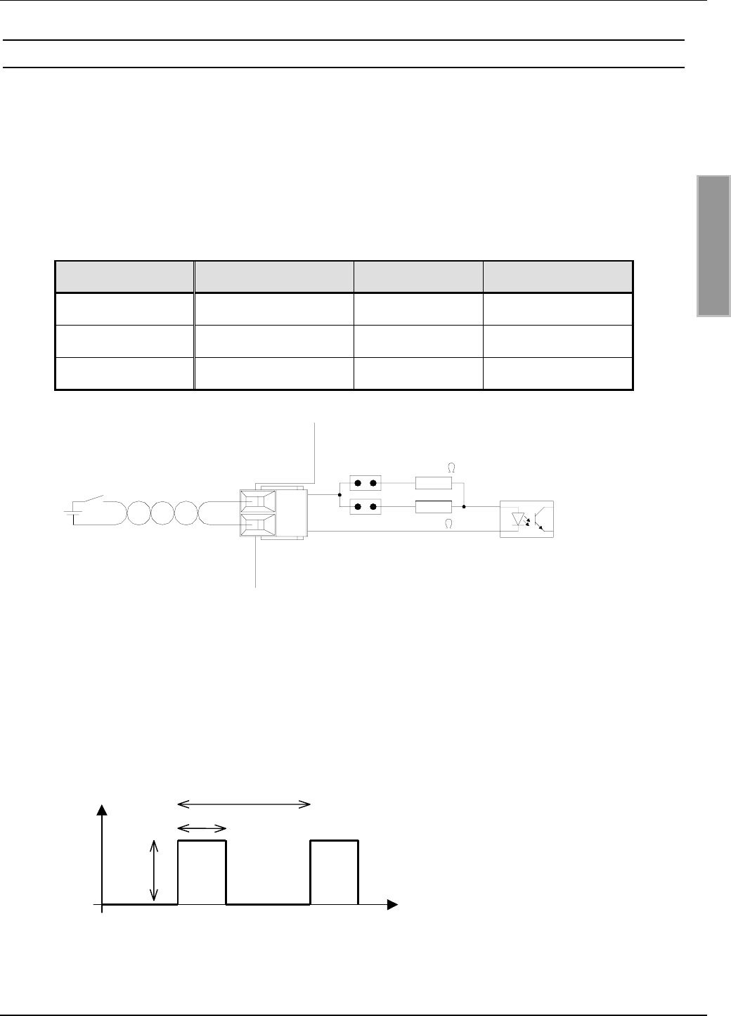
3.4. X2: Eingang (Optokoppler)
Der digitale Eingang an Klemmleiste X2 dient zum triggern des Multiplexers im Extern-Trigger
Mode. Der Optokopplereingang ist galvanisch vom Antennenmultiplexer getrennt und muss daher
mit einer externen Gleichspannung versorgt werden. Die Eingangs-LED des Optokopplers ist in-
tern mit einem Serienwiderstand beschaltet, dessen Größe über die Jumper JP11 und JP12 ein-
stellbar ist (s. Bild 4). Der Eingangsstrom sollte zwischen 10 mA und 20 mA liegen. Je nach Ein-
gangsspannung sind Jumpereinstellungen gemäß Tab. 1 vorzunehmen.
Tab. 1: Jumpereinstellung für Optokopplereingang
ext. Spannung Uext Rint JP19 JP20
5 V – 8 V 350 Ωgesetzt gesetzt
8 V – 12 V 500 Ωgesetzt offen
12 V – 24 V 1,2 kΩoffen gesetzt
Bild 4: Eingang
Das Triggersignals an Eingang X2 muss innerhalb der in Bild 5 angegebenen Grenzwerte liegen.
Bei hohen Schaltfrequenzen ist es sinnvoll, das Triggersignal und die Transponderprotokolle zu
synchronisieren, um nicht während des Auslesens eines Transponders die Verbindung zwischen
Reader und Transponder zu unterbrechen.
Bild 5: Signal für externen Trigger
X2
1,2 k
500
JP20
JP19
tb
Up
U
t
tb: 1 – 100 ms
tp: > ( tb + 1 ms )
Up: 5 – 24 VDC
tp
OBID i-scanMontage ID ISC.ANT.MUX
FEIG ELECTRONIC GmbH Seite 10 von 37 M30201-1de-ID-B.doc
D E U T S C H
3.5. IN1-2: Readeranschluss
Der Anschluss an einen Reader erfolgt über das Antennenkabel an die SMA-Buchsen IN1
und/oder IN2. Das maximale Anzugsdrehmoment der SMA-Buchsen beträgt 0,45 Nm. Die Koaxi-
alkabel zum Readeranschluss sind jeweils durch die seitlichen Kabelverschraubungen zu führen
(s. Bild 6).
Bild 6: Readeranschluss
Hinweis:
Für das Erreichen optimaler Lesereichweiten sollte das Koaxialkabel entweder kleiner
50 cm oder 7,20 m lang sein.
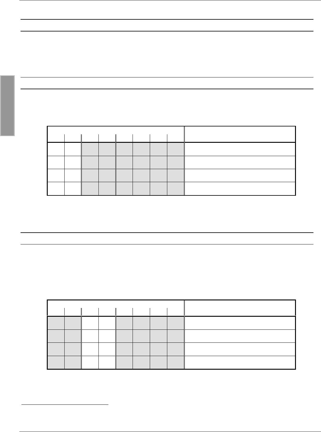
3.6. OUT1-8: Antennenanschluss
Die Antennen sind mit Koaxialkabel über die SMA-Buchsen OUT1-8 anzuschließen. Das maximale
Anzugsdrehmoment der SMA-Buchsen beträgt 0,45 Nm. Die Anschlüsse an die SMA-Buchsen
OUT1-4 sind durch die oberen Kabelverschraubungen und die Anschlüsse an OUT5-8 durch die
unteren Kabelverschraubungen zu führen (s. Bild 7)
Bild 7: Antennenanschlüsse

OBID i-scanMontage ID ISC.ANT.MUX
FEIG ELECTRONIC GmbH Seite 11 von 37 M30201-1de-ID-B.doc
D E U T S C H
4. Bedien- und Anzeigeelemente
4.1. LEDs
Die LEDs, die sich an den SMA-Buchsen OUT1-8 befinden (LEDout1-8), signalisieren, ob der ent-
sprechende Kanal durchgeschaltet oder gesperrt ist. Im durchgeschalteten Zustand des Kanals
leuchtet die jeweilige LED.
In Tab. 2 sind die Funktionen der LEDs LED1-3 aufgelistet:
Tab. 2: Funktion LED1-3
Kurzzeichen Farbe Beschreibung
LED1 rot Diagnose 1: „Kommunikations-LED“
HF-Communikation Control Mode:
- Blinkt auf, wenn der Multiplexer ein
Signal vom Reader über die SMA-
Buchse IN1 erhalten hat.
- Leuchtet, wenn Multiplexer Fehler am
Ausgang detektiert hat.
Extern-Trigger Mode:
- Blinkt auf, wenn der Multiplexer einen
gültigen Impuls über X2 erhalten hat.
LED2 grün Diagnose 2: „HF-LED“
Leuchtet, wenn ein HF-Signal an der SMA-
Buchse IN1 anliegt.
LED3 grün „RUN-LED“:
Signalisiert durch Blinken (ca. 1 Hz) den
ordnungsgemäßen Ablauf der internen Soft-
ware.
OBID i-scanMontage ID ISC.ANT.MUX
FEIG ELECTRONIC GmbH Seite 12 von 37 M30201-1de-ID-B.doc
D E U T S C H
4.2. DIP-Schalter S1
Über die DIP-Schalter S1 können die verschiedenen Multiplexermodi und Adressierungen einge-
stellt werden. Nach einem Umstellen der DIP-Schalter muss ein Power-Up-Reset durchgeführt
werden, indem die Versorgungsspannung kurz unterbrochen wird.
4.2.1. Einstellen der Modi
Die Einstellung der Modi erfolgt über die DIP-Schalter 1 und 2. In Tab. 3 sind die Einstellungen
zusammengefasst.
Tab. 3: Einstellung der Modi
DIP-Schalter S1 Adresse
12345678
-- reserviert
-ON Extern-Trigger Mode1
ON - HF-Communikation Control Mode2
ON ON reserviert
4.2.2. Adresseinstellung im HF-Communikation Control Mode
Mit den DIP-Schaltern kann für den HF-Communikation Control Mode eine Adresseinstellung vor-
genommen werden. Dabei wird über die DIP-Schalter 3 und 4 die Ebene3 eingestellt. In Tab. 4
sind die Einstellungen der Ebenen zusammengefasst:
Tab. 4: Adressierung im HF-Communikation Control Mode
DIP-Schalter S1 Adresse / Ebene
12345678
ON --- nicht genutzt
ON --ON Ebene 1
ON -ON - Ebene 2
ON -ONON Ebene 3
1 siehe 5.2. Extern-Trigger Mode
2 siehe 5.1. HF-Communikation Control Mode
3 siehe auch Handbuch H30701-#d-ID-B.doc
OBID i-scanMontage ID ISC.ANT.MUX
FEIG ELECTRONIC GmbH Seite 13 von 37 M30201-1de-ID-B.doc
D E U T S C H
4.2.3. Einstellung Single- oder Dual-Mode im Extern-Trigger Mode
Im Extern-Trigger Mode kann der Multiplexer im Single- oder im Dual-Mode betrieben werden. Im
Single-Mode ist immer nur ein Ausgang durchgeschaltet, im Dual-Mode zwei, je ein Ausgang für
IN1 und IN2.
Der Dual-Mode wird durch Zuschalten der DIP-Schalter 3 und 4 aktiviert. Ansonsten ist der Single-
Mode eingestellt (s. Tab. 5).
4.2.4. Einstellung Anzahl Ausgänge im Extern-Trigger Mode
Über die DIP-Schalter 5-8 wird die Anzahl der verwendeten Ausgänge im Single- bzw. Dual-Mode
eingestellt:
Tab. 5: Einstellung Anzahl der Ausgänge im Single- und Dual-Mode
DIP-Schalter S1 Kanäle
12345678
Single-Mode
-ON -----ONKanal 1
-ON - - - - ON - Kanal 1-2
-ON - - - - ON ON Kanal 1-3
-ON - - - ON - - Kanal 1-4
-ON - - - ON - ON Kanal 1-5
-ON - - - ON ON - Kanal 1-6
-ON - - - ON ON ON Kanal 1-7
-ON - - ON - - - Kanal 1-8
Dual-Mode
-ON ON ON - - - ON Kanal 1+8
-ON ON ON - - ON - Kanal 1+8, 2+7
-ON ON ON - - ON ON Kanal 1+8, 2+7, 3+6
-ON ON ON - ON - - Kanal 1+8, 2+7, 3+6, 4+5
OBID i-scanMontage ID ISC.ANT.MUX
FEIG ELECTRONIC GmbH Seite 14 von 37 M30201-1de-ID-B.doc
D E U T S C H
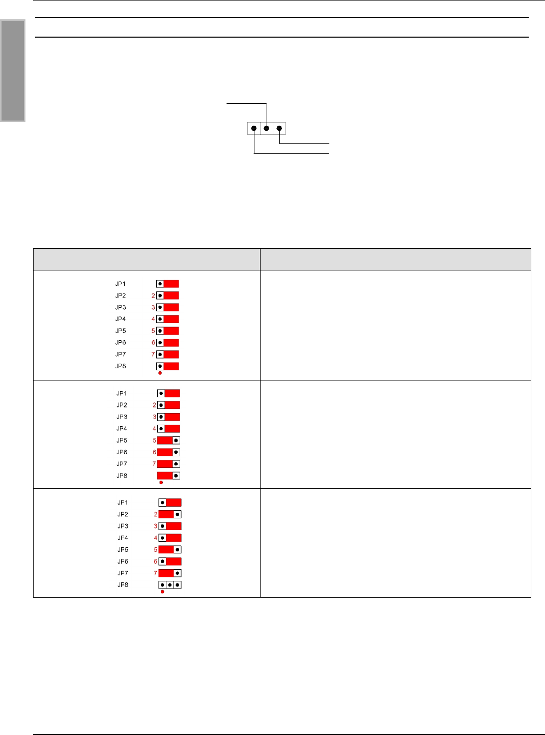
4.3. Jumper JP1- 8
Über die Jumper 1-8 können den Eingängen IN1 und IN2 die entsprechenden Ausgänge OUT1-8
zugewiesen werden (s. Bild 8).
Bild 8: Zuweisung des Ausgangs OUTx
Bei nicht verwendeten Ausgängen ist die Stellung des entsprechenden Jumpers nicht von Bedeu-
tung. In Tab. 6 sind 3 Beispiel aufgeführt:
Tab. 6 Beispiel Jumperstellung JP1-8
Jumperstellung Zuordnung
Die Jumper JP1-8 stehen alle auf Position 2-3.
Alle Ausgänge (OUT1-8) sind damit dem Eingang
IN1 zugeordnet.
Die Jumper JP1-4 stehen auf Position 2-3, die Jum-
per JP5-8 auf Position 1-2.
Damit sind die Ausgänge OUT1-4 dem Eingang IN1
und die Ausgänge OUT4-8 dem Eingang IN2 zuge-
ordnet.
JP1, JP3, JP4 und JP6 stehen auf Position 2-3; JP2,
JP5 und JP7 auf Position 1-2
Damit sind die Ausgänge OUT1, 3, 4, 6 dem
Eingang IN1 und die Ausgänge OUT2, 5, 7 dem
Eingang IN2 zugeordnet. Der Ausgang OUT8 ist
keinem Eingang zugeordnet.
JPx
OUTx
IN1
IN2
1

OBID i-scanMontage ID ISC.ANT.MUX
FEIG ELECTRONIC GmbH Seite 15 von 37 M30201-1de-ID-B.doc
D E U T S C H
4.4. Jumper JP11 – JP18
Durch setzen der Jumper JP11 - JP18 wird dem entsprechenden Ausgang OUT1 – OUT8 eine
DC-Offset von + 7V zugeschaltet. Der maximale Gleichstrom, der über die Ausgänge fließen darf,
beträgt 100mA.
4.5. Jumper JP19 und JP20
Mit den Jumpern JP19 und JP20 wird der Eingangswiderstand des Optokopplereingangs an X2
eingestellt. In Tab. 1 (Kapitel 3.4. X2: Eingang (Optokoppler)) sind die möglichen Einstellungen
aufgelistet.
OBID i-scanMontage ID ISC.ANT.MUX
FEIG ELECTRONIC GmbH Seite 16 von 37 M30201-1de-ID-B.doc
D E U T S C H
5. Inbetriebnahme
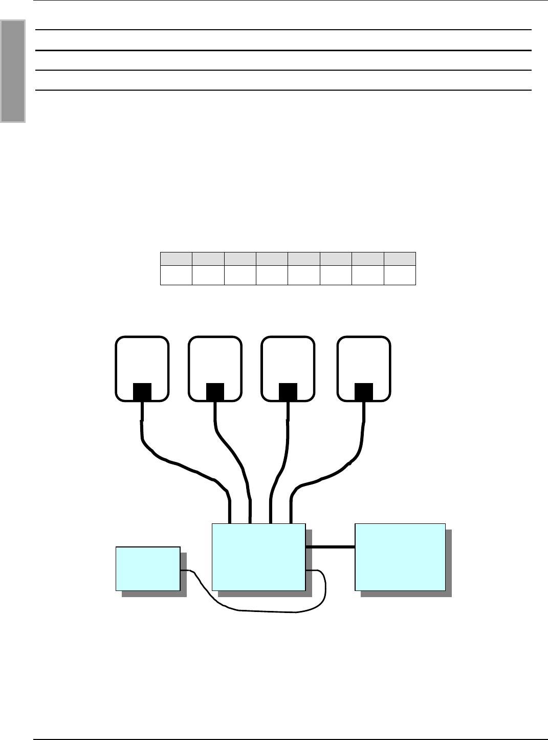
5.1. HF-Communikation Control Mode
Im HF-Communikation Control Mode wird der Multiplexer über Protokolle vom Reader gesteuert.
Es ist kein zusätzliches Kabel zwischen Reader und Multiplexer notwendig. Die Protokolle sind im
Handbuch H30701-#d-ID-B aufgeführt.
Durch die Kommunikation zwischen Reader und Multiplexer ist ein gezieltes Schalten bestimmter
Ausgänge möglich.
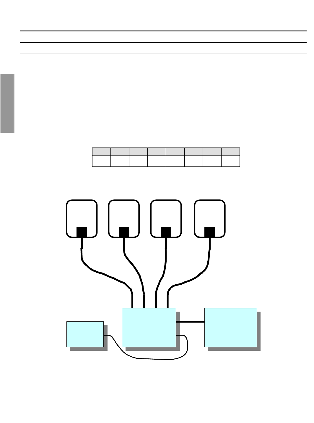
Bild 9 zeigt ein einfaches Anwendungsbeispiel mit einem Multiplexer und vier Antennen. Folgende
DIP-Schalterstellung ist dabei vorzunehmen (s. 4.2. DIP-Schalter S1):
Tab. 7: DIP-Schalterstellung
12345678
ON--ON----
Bild 9: Anwendungsbeispiel mit vier Antennen im HF-Communikation Control Mode
Reader
OUT1-4
IN1
MUX
X1
50cm
Antennen
12-24VDC
OBID i-scanMontage ID ISC.ANT.MUX
FEIG ELECTRONIC GmbH Seite 17 von 37 M30201-1de-ID-B.doc
D E U T S C H
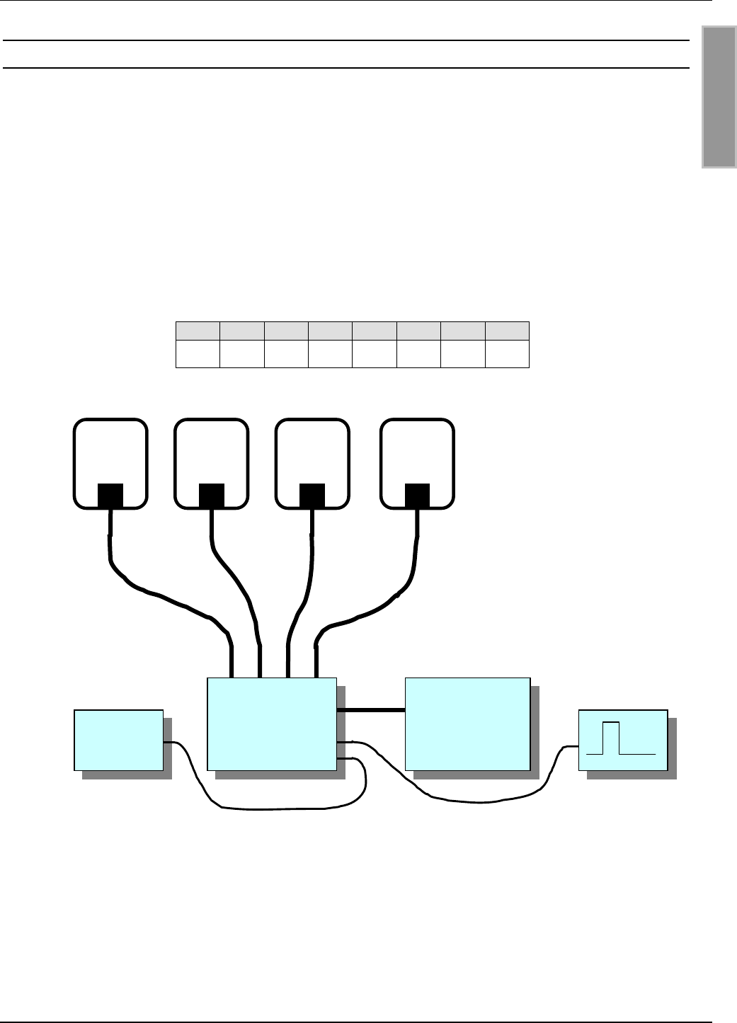
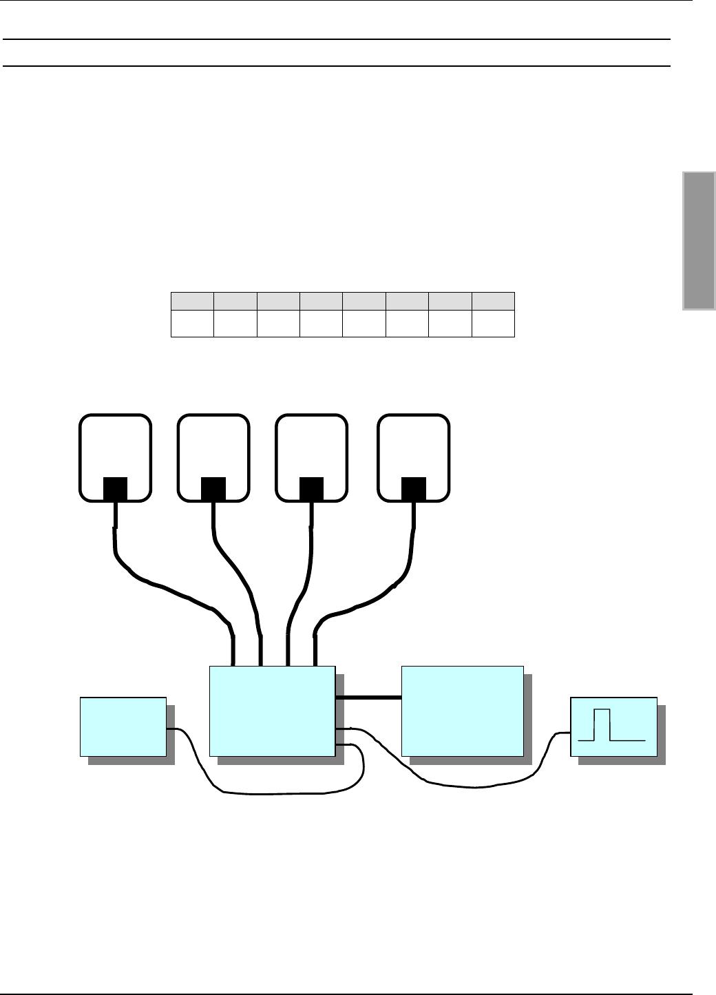
5.2. Extern-Trigger Mode
Im Extern-Trigger Mode wird der Multiplexer über den Eingang X2 gesteuert (s. 3.4. X2: Eingang
(Optokoppler)). Dabei werden die eingestellten Ausgänge nacheinander in numerischer Reihenfol-
ge durchgeschaltet.
Die Jumperstellungen der Jumper JP19 und JP20 sowie die Pulsbreite des externen Triggersignal
ist in Kap. 3.4. X2: Eingang (Optokoppler) beschrieben.
Bild 10 zeigt ein einfaches Anwendungsbeispiel mit einem Multiplexer und vier Antennen. Folgen-
de DIP-Schalterstellung ist dabei vorzunehmen (s. 4.2. DIP-Schalter S1):
Tab. 8: DIP-Schalterstellung
12345678
-ON---ON--
Bild 10: Beispielanwendung mit vier Antennen im Extern-Trigger Mode
Reader
OUT1-4
IN1
MUX
X2
X1
50cm
Antennen
12-24VDC

OBID i-scanMontage ID ISC.ANT.MUX
FEIG ELECTRONIC GmbH Seite 18 von 37 M30201-1de-ID-B.doc
D E U T S C H
ANHANG A: Technische Daten
Mechanische Daten
• Abmessungen ( B x H x T ) 182 mm x 110 mm x 90 mm
• Gewicht ca. 550 g
• Schutzart IP65
• Kabeldurchführung 12 x Kabelverschraubung M16 x 1,5
Elektrische Daten
• Spannungsversorgung 12 - 24 V DC
• Leistungsaufnahme max. 4 W
• Betriebsfrequenz 13,56 MHz
• Dämpfung pro Kanal max. 0,5 dB
• max. zul. Schaltleistung 10 W
• RF-Anschlüsse
- 2 x Eingang
- 8 x Ausgang
SMA Buchse (50 Ω) *
SMA Buchse (50 Ω) *
• RF Schalter
– Schaltgeschwindigkeit
elektronische Schalter (verschleißfrei)
< 1 ms
• Ansteuerung
– Reader
– externer Pulsgeber
Kommunikation über RF Eingang 1
externer Trigger
• Eingänge
- 1 x Optokoppler (externer Trigger) 5 – 24 V DC/ 20 mA (Pulsbreite 1ms – 100ms)
• Signalgeber 1 x LED pro Kanal
3 x LED ( Run / HF / Kommunikation )
* Maximales Anzugsdehmoment: 0,45Nm

OBID i-scanMontage ID ISC.ANT.MUX
FEIG ELECTRONIC GmbH Seite 19 von 37 M30201-1de-ID-B.doc
D E U T S C H
Umgebungsbedingungen
• Temperaturbereich
– Betrieb
– Lagerung
-25°C bis +65°C
-40°C bis +80°C
• EMV EN61000-6-3
EN61000-6-2
• Vibration EN60068-2-6
10 Hz bis 150 Hz : 0,075 mm / 1 g
• Schock EN60068-2-27
Beschleunigung : 30 g

OBID i-scanMontage ID ISC.ANT.MUX
FEIG ELECTRONIC GmbH Seite 20 von 37 M30201-1de-ID-B.doc
D E U T S C H

OBID i-scanInstallation ID ISC.ANT.MUX
FEIG ELECTRONIC GmbH Page 21 of 37 M30201-1de-ID-B.doc
E N G L I S H
Note
Copyright 2003 by
FEIG ELECTRONIC GmbH
Lange Strasse 4
D-35781 Weilburg-Waldhausen
Tel.: +49 6471 3109-0
http://www.feig.de
With the edition of this document, all previous editions become void. Indications made in this manual may be
changed without previous notice.
Copying of this document, and giving it to others and the use or communication of the contents thereof are
forbidden without express authority. Offenders are liable to the payment of damages. All rights are reserved
in the event of the grant of a patent or the registration of a utility model or design.
Composition of the information in this manual has been done to the best of our knowledge.
FEIG ELECTRONIC GmbH does not guarantee the correctness and completeness of the details given in this
manual and may not be held liable for damages ensuing from incorrect or incomplete information. Since,
despite all our efforts, errors may not be completely avoided, we are always grateful for your useful tips.
The installation instructions given in this manual are based on advantageous boundary conditions.
FEIG ELECTRONIC GmbH does not give any guarantee promise for perfect function in cross environments.
FEIG ELECTRONIC GmbH assumes no responsibility for the use of any information contained in this
manual and makes no representation that they free of patent infringement. FEIG ELECTRONIC GmbH does
not convey any license under its patent rights nor the rights of others.
OBID i-scan is registered trademark of FEIG ELECTRONIC GmbH.

OBID i-scanInstallation ID ISC.ANT.MUX
FEIG ELECTRONIC GmbH Page 22 of 37 M30201-1de-ID-B.doc
E N G L I S H
Content
6. Safety Instructions / Warning - Read before Start-Up ! 23
7. Performance Features of the ID ISC.ANT.MUX 8x Antenna Multiplexer 24
7.1. Performance Features.................................................................................................... 24
7.2. Scope of Delivery ........................................................................................................... 24
8. Wiring and Installation 25
8.1. Installing the Enclosure ................................................................................................. 25
8.2. Terminals and Jacks ...................................................................................................... 26
8.3. X1: Supply Voltage ......................................................................................................... 26
8.4. X2: Input (Opto-Coupler)................................................................................................ 27
8.5. IN1-2: Reader Connection.............................................................................................. 28
8.6. OUT1-8: Antenna Connection........................................................................................ 28
9. Operating and Display Elements 29
9.1. LEDs................................................................................................................................ 29
9.2. DIP Switch S1 ................................................................................................................. 30
9.2.1. Setting the Modes ..................................................................................................... 30
9.2.2. Address Setting in HF Communication Control Mode................................................ 30
9.2.3. Setting Single or Dual Mode in External Trigger Mode .............................................. 31
9.2.4. Setting Number of Outputs in External Trigger Mode ................................................ 31
9.3. Jumpers JP1- 8............................................................................................................... 32
9.4. Jumpers JP11 - JP18...................................................................................................... 33
9.5. Jumpers JP19 and JP20................................................................................................ 33
10. Start-Up 34
10.1. HF Communication Control Mode............................................................................... 34
10.2. External Trigger Mode.................................................................................................. 35
APPENDIX A: Technical Data 36

OBID i-scanInstallation ID ISC.ANT.MUX
FEIG ELECTRONIC GmbH Page 23 of 37 M30201-1de-ID-B.doc
E N G L I S H
6. Safety Instructions / Warning - Read before Start-Up !
• The device may only be used for the intended purpose designed by for the manufacturer.
• The operation manual should be conveniently kept available at all times for each user.
• Unauthorized changes and the use of spare parts and additional devices which have not been
sold or recommended by the manufacturer may cause fire, electric shocks or injuries. Such
unauthorized measures shall exclude any liability by the manufacturer.
• The liability-prescriptions of the manufacturer in the issue valid at the time of purchase are valid
for the device. The manufacturer shall not be held legally responsible for inaccuracies, errors,
or omissions in the manual or automatically set parameters for a device or for an incorrect
application of a device.
• Repairs may only be executed by the manufacturer.
• Installation, operation, and maintenance procedures should only be carried out by qualified
personnel.
• Before opening the device, the power supply must always be disconnected . Make sure that
the device is without voltage by measuring with a test instrument. CAUTION! The fading
illumination of an operational control (LED) should not be used as a sufficient indicator for an
interrupted power supply or the device being without voltage!
• Use of t the device and its installation must be in accordance with national legal
requirements and local electrical codes .

OBID i-scanInstallation ID ISC.ANT.MUX
FEIG ELECTRONIC GmbH Page 24 of 37 M30201-1de-ID-B.doc
E N G L I S H
7. Performance Features of the ID ISC.ANT.MUX 8x Antenna Multiplexer
7.1. Performance Features
The ID ISC.ANT.MUX 8x antenna multiplexer is designed for switching RFID antennas having an
operating frequency of 13.56 MHz. An ID ISC.ANT.MUX allows multiple individual antennas (base
antennas) or gate antennas (base + complementary antennas) to be operated with just a single
reader. All eight outputs on the antenna multiplexer can be assigned to each of the two inputs by
means of jumper settings.
It is possible to cascade several ID ISC.ANT.MUX to increase the number of possible antenna
connections. Here the antenna multiplexers are addressed using DIP switch settings.
7.2. Scope of Delivery
The following components are included:
y 8x antenna multiplexer ID ISC.ANT.MUX
y 8 x protection caps for M16 cable fitting
y Installation Guide
OBID i-scanInstallation ID ISC.ANT.MUX
FEIG ELECTRONIC GmbH Page 25 of 37 M30201-1de-ID-B.doc
E N G L I S H
8. Wiring and Installation
8.1. Installing the Enclosure
The antenna multiplexer is designed for a wall mounted installation,and is suitable for outdoor. For
wall attachment, break-outs are located in the corners of the enclosure (see Figure 1).
Figure 1: Dimensions and mounting holes
The cable fittings are M16 x 1.5 for a clamping range of 4.5mm to 10mm.
180
165
95
110
4 x ø5
OBID i-scanInstallation ID ISC.ANT.MUX
FEIG ELECTRONIC GmbH Page 26 of 37 M30201-1de-ID-B.doc
E N G L I S H
8.2. Terminals and Jacks
Figure 2 shows the terminals, jacks, DIP switches, jumpers and LED indicators.
Figure 2: Terminals, jacks and operating elements
8.3. X1: Supply Voltage
The supply voltage is connected to X1. Configure the polarity as shown in Figure 3. The antenna
multiplexer operates with a DC voltage of 12V to 24V.
Figure 3: Supply voltage connection
X1
12-24V DC
GND
JP15 JP16 JP17 JP18
JP14 JP13 JP12 JP11
12345678
ON
OFF IN
1
IN
2
OUT 1OUT 2OUT 3OUT 4
OUT 8OUT 7OUT 6OUT 5
S1
JP1
JP2
JP3
JP4
JP5
JP6
JP7
JP8
JP20
JP19
X1
X2
X3
LED1 LED2 LED3
LEDout5 LEDout6 LEDout7 LEDout8
LEDout1LEDout2LEDout3LEDout4
OBID i-scanInstallation ID ISC.ANT.MUX
FEIG ELECTRONIC GmbH Page 27 of 37 M30201-1de-ID-B.doc
E N G L I S H
8.4. X2: Input (Opto-Coupler)
The digital input on terminal X2 is used to trigger the multiplexer in the External-Trigger mode. The
opto-coupler input is galvanically isolated from the antenna multiplexer and must therefore be
externally supplied with DC voltage. The input LED on the opto-coupler is internally connected to a
series resistor whose value is adjustable using jumpers JP11 and JP12 (s. Figure 4). The input-
current should be between 10mA and 20mA. Set the jumpers according to Table 1 depending on
the input voltage.
Table 1: Jumper settings for opto-coupler input
ext. voltage Uext Rint JP19 JP20
5V – 8V 350 ΩIn In
8V – 12V 500 ΩIn Out
12V – 24V 1,2 kΩOut In
Figure 4: Input
The trigger signal on input X2 must lie within the limits shown in Figure 5. With higher frequencies
it is recommended that the trigger signal and the transponder protocols be synchronized to prevent
the connection between the reader and data carrier from being interrupted while a transponder is
being read.
Figure 5: Pulse for external trigger
X2
1,2 k
500
JP20
JP19
tb
Up
U
t
tb: 1 – 100ms
tp: > ( tb + 1ms )
Up: 5 – 24VDC
tp
OBID i-scanInstallation ID ISC.ANT.MUX
FEIG ELECTRONIC GmbH Page 28 of 37 M30201-1de-ID-B.doc
E N G L I S H
8.5. IN1-2: Reader Connection
The connection to a reader is made using coaxial cable to the SMA jacks IN1 and/or IN2. The
maximum tightening torque of the SMA jacks is 0.45 Nm. The coax cables to the reader terminal
should be routed through the sidewise cable fittings (see Figure 6).
Figure 6: Reader connection
Note:
For optimum read distance, the coax cable should be either less than 50cm or 7.20m in length.
8.6. OUT1-8: Antenna Connection
The antennas are connected using coaxial cable to the SMA jacks OUT1-8. The maximum
tightening torque of the SMA jacks is 0.45 Nm. The connections to the SMA jacks OUT1-4 are
made through the upper cable fittings, and the connections to OUT5-8 through the lower cable
fittings (see Figure 7).
Figure 7: Antenna connections

OBID i-scanInstallation ID ISC.ANT.MUX
FEIG ELECTRONIC GmbH Page 29 of 37 M30201-1de-ID-B.doc
E N G L I S H
9. Operating and Display Elements
9.1. LEDs
The LEDs, located on the SMA jacks OUT1-8 (LEDout1-8), indicate whether the corresponding
channel is switched or open. When a channel is switched, the corresponding LED will be on.
Table 2 shows the functions of LEDs LED1-3:
Table 2: LED1-3 function
Abbreviation Color Description
LED1 red Diagnostic 1: „Communication-LED“
HF-Communication Control Mode:
- Flashes on when the multiplexer has
received a signal from the reader through
SMA jack IN1.
- Comes on when multiplexer has detected
an error at an output.
External Trigger Mode:
- Flashes on when the multiplexer has
received a valid pulse through X2.
LED2 green Diagnostic 2: „HF-LED“
Comes on when an HF-signal is present on
SMA jack IN1.
LED3 green „RUN-LED“:
Flashes (approx. 1Hz) when the internal
software is running properly.
OBID i-scanInstallation ID ISC.ANT.MUX
FEIG ELECTRONIC GmbH Page 30 of 37 M30201-1de-ID-B.doc
E N G L I S H
9.2. DIP Switch S1
DIP switch S1 can be used to set the various multiplexer modes and addresses. After changing the
DIP switch setting, you must perform a Power-Up Reset by briefly interrupting the supply voltage.
9.2.1. Setting the Modes
The modes are set using DIP switches 1 and 1. Table 3 shows a summary of the settings.
Table 3: Setting modes
DIP switch S1 Address
12345678
-- Reserved
-ON External Trigger Mode4
ON - HF Communication Control Mode5
ON ON Reserved
9.2.2. Address Setting in HF Communication Control Mode
The DIP switches can be used to set addresses for HF Communication Control Mode. DIP
switches 3 and 4 are used for setting the corresponding level6. Table 4 summarizes the settings for
the levels.
Table 4: Address setting in HF Communication Control Mode
DIP switch S1 Address / Level
12345678
ON --- not used
ON --ON Level 1
ON -ON- Level 2
ON -ONON Level 3
4 see 10.2. External Trigger Mode
5 see 10.1. HF Communication Control Mode
6 Reference Manual H30701-#e-ID-B.doc
OBID i-scanInstallation ID ISC.ANT.MUX
FEIG ELECTRONIC GmbH Page 31 of 37 M30201-1de-ID-B.doc
E N G L I S H
9.2.3. Setting Single or Dual Mode in External Trigger Mode
In the external trigger mode the multiplexer can be used in single or dual mode. In single mode you
can only switch on one output. In dual mode you can switch on two outputs, one for IN1 and one
for IN2.
The dual mode is activated by turning on DIP switches 3 and 4. Otherwise the single mode is acti-
vated (see Table 5).
9.2.4. Setting Number of Outputs in External Trigger Mode
DIP switches 5-8 are used to set the number of outputs used in Single or Dual Mode:
Table 5: Setting number of outputs in Single and Dual Mode
DIP switch S1 Channels
12345678
Single-Mode
-ON-----ONChannel 1
-ON - - - - ON - Channel 1-2
-ON - - - - ON ON Channel 1-3
-ON - - - ON - - Channel 1-4
-ON - - - ON - ON Channel 1-5
-ON - - - ON ON - Channel 1-6
-ON - - - ON ON ON Channel 1-7
-ON - - ON - - - Channel 1-8
Dual-Mode
-ON ON ON - - - ON Channel 1+8
-ON ON ON - - ON - Channel 1+8, 2+7
-ON ON ON - - ON ON Channel 1+8, 2+7, 3+6
-ON ON ON - ON - - Channel 1+8, 2+7, 3+6, 4+5
OBID i-scanInstallation ID ISC.ANT.MUX
FEIG ELECTRONIC GmbH Page 32 of 37 M30201-1de-ID-B.doc
E N G L I S H
9.3. Jumpers JP1- 8
Jumpers 1-8 can be used to assign the corresponding outputs OUT1-8 to the inputs IN1 and IN2
(see Figure 8).
Figure 8: Assigning of output OUTx
The jumper position has no meaning for outputs which are not used. Table 6 shows two examples:
Table 6: Examples for jumper settings JP1-8
Jumper setting Assignment
Jumpers JP1-8 are all at position 2-3.
All outputs (OUT1-8) are then assigned to input IN1.
Jumpers JP1-4 are at position 2-3, jumpers JP5-8 at
position 1-2.
This assigns outputs OUT1-4 to input IN1 and
outputs OUT4-8 to input IN2.
JP1, JP3, JP4 and JP6 are at position 2-3; JP2, JP5
and JP7 at position 1-2
This assigns outputs OUT1, 3, 4, 6 to input IN1 and
outputs OUT2, 5, 7 to input IN2. Output OUT8 is not
assigned to an input.
JPx
OUTx
IN1
IN2
1

OBID i-scanInstallation ID ISC.ANT.MUX
FEIG ELECTRONIC GmbH Page 33 of 37 M30201-1de-ID-B.doc
E N G L I S H
9.4. Jumpers JP11 - JP18
With the Jumpers JP11 – JP18 a DC-Offset of + 7V is switched on to the according output OUT1 –
OUT8. The maximum DC-current for one output is 100mA.
9.5. Jumpers JP19 and JP20
Jumpers JP19 and JP20 are used to set the input resistance for the opto-coupler input on X2.
Table 1 (Section 8.4. X2: Input (Opto-Coupler)) lists the possible settings.
OBID i-scanInstallation ID ISC.ANT.MUX
FEIG ELECTRONIC GmbH Page 34 of 37 M30201-1de-ID-B.doc
E N G L I S H
10. Start-Up
10.1. HF Communication Control Mode
In HF Communication Control Mode the multiplexer is controlled by protocols from the reader. No
additional cable between the reader and multiplexer is necessary. The protocols are described in
the system manual for the H30701-#e-ID-B.
The communication between the reader and multiplexer allows specific switching to a particular
outputs.
Figure 9 shows a simple application example with a multiplexer and four antennas. Use the
following DIP switch setting (see 9.2. DIP Switch S1):
Table 7: DIP switch setting
12345678
ON--ON----
Figure 9: Application example with four antennas in HF Communication Control Mode
Reader
OUT1-4
IN1
MUX
X1
50cm
Antennas
12-24VDC
OBID i-scanInstallation ID ISC.ANT.MUX
FEIG ELECTRONIC GmbH Page 35 of 37 M30201-1de-ID-B.doc
E N G L I S H
10.2. External Trigger Mode
In External Trigger Mode the multiplexer is controlled through input X2 (see 3.4. X2: Eingang
(Optokoppler)). The set outputs are switched on one after the other in numerical order.
Jumper settings for jumpers JP19 and JP20 as well the pulse width of the external trigger signal is
described in section 3.4. X2: Eingang (Optokoppler).
Figure 10 shows a simple application example with one multiplexer and four antennas. Use the
following DIP switch settings (see 9.2. DIP Switch S1):
Table 8: DIP switch setting
12345678
-ON---ON--
Figure 10: Application example with four antennas in External Trigger Mode
Reader
OUT1-4
IN1
MUX
X2
X1
50cm
Antennas
12-24VDC

OBID i-scanInstallation ID ISC.ANT.MUX
FEIG ELECTRONIC GmbH Page 36 of 37 M30201-1de-ID-B.doc
E N G L I S H
APPENDIX A: Technical Data
Mechanical Data
• Dimensions ( W x H x D ) 182mm x 110mm x 90mm
• Weight approx. 550 g
• Enclosure rating IP65
• Cable fittings 12 x cable fitting M16 x 1.5
Electrical Data
• Supply voltage 12 - 24 V DC
• Power consumption max. 4 W
• Operating frequency 13.56 MHz
• Attenuation per channel max. 0.5dB
• max. Permissible switching power 10 W
• RF connections
- 2 x input
- 8 x output
SMA jack (50Ω) *
SMA jack (50Ω) *
• RF switches
– Switching speed
Electronic switches (non-wearing)
< 1ms
• Triggering
– Reader
– external pulse generator
Communication via RF input 1
External trigger
• Inputs
- 1 x Opto-coupler (external trigger) 5 - 24 V DC/ 20 mA (pulse width 1ms – 100ms)
• Signal indicator 1 x LED per channel
3 x LED ( Run / HF / Communication )
* Maximum tightening torque: 0.45Nm

OBID i-scanInstallation ID ISC.ANT.MUX
FEIG ELECTRONIC GmbH Page 37 of 37 M30201-1de-ID-B.doc
E N G L I S H
Ambient Conditions
• Temperature range
– Operating
– Storage
-25°C to +65°C
-40°C to +80°C
• EMC EN61000-6-3
EN61000-6-2
• Vibration EN60068-2-6
10 Hz to 150 Hz :0.075 mm / 1 g
• Shock EN60068-2-27
Acceleration : 30 g
INSTALLATION
final
public (B)
2017-10-24
M50101-2de-ID-B.doc
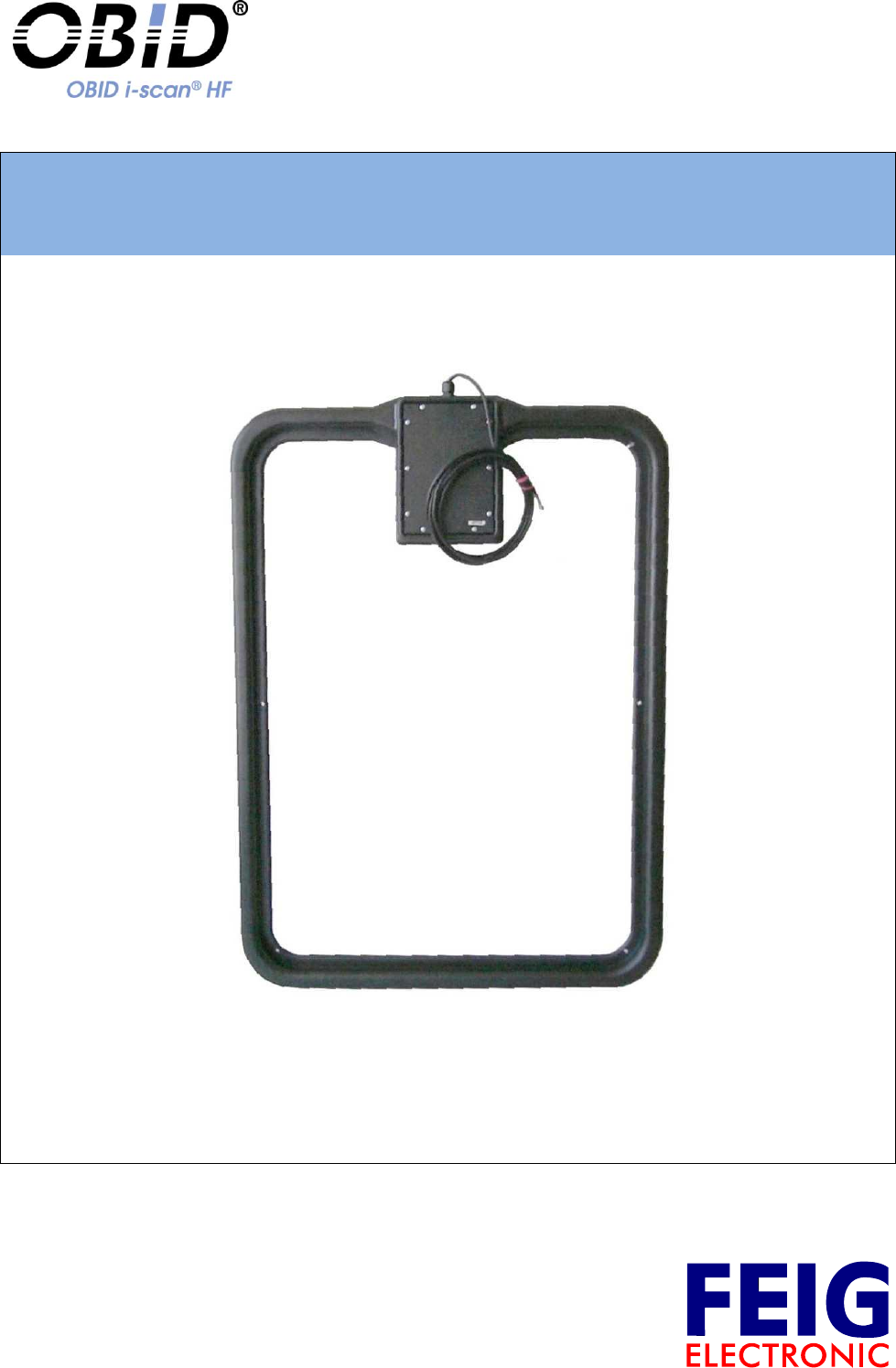
ID ISC.ANT800/600-DA
Antenna with dynamic Tuner and Reader ID ISC.LR2500
(deutsch / english)


OBID i-scan®
Montage
ID ISC.ANT800/600-DA
FEIG ELECTRONIC GmbH
Seite 3 von 42
M50101-2de-ID-B.doc
D E U T S C H
Hinweis
Copyright 2005-2012 by
FEIG ELECTRONIC GmbH
Lange Straße 4
D-35781 Weilburg
Tel.: +49 6471 3109-0
http://www.feig.de
Alle früheren Ausgaben verlieren mit dieser Ausgabe ihre Gültigkeit.
Die Angaben in diesem Dokument können ohne vorherige Ankündigung geändert werden.
Weitergabe sowie Vervielfältigung dieses Dokuments, Verwertung und Mitteilung ihres Inhalts sind nicht
gestattet, soweit nicht ausdrücklich zugestanden. Zuwiderhandlung verpflichtet zu Schadenersatz. Alle
Rechte für den Fall der Patenterteilung oder Gebrauchsmuster-Eintragung vorbehalten.
Die Zusammenstellung der Informationen in diesem Dokument erfolgt nach bestem Wissen und Gewissen.
FEIG ELECTRONIC GmbH übernimmt keine Gewährleistung für die Richtigkeit und Vollständigkeit der An-
gaben in diesem Dokument. Insbesondere kann FEIG ELECTRONIC GmbH nicht für Folgeschäden auf
Grund fehlerhafter oder unvollständiger Angaben haftbar gemacht werden. Da sich Fehler, trotz aller Bemü-
hungen nie vollständig vermeiden lassen, sind wir für Hinweise jederzeit dankbar.
Die in diesem Dokument gemachten Installationsempfehlungen gehen von günstigsten Rahmenbedingun-
gen aus. FEIG ELECTRONIC GmbH übernimmt keine Gewähr für die einwandfreie Funktion in systemfrem-
den Umgebungen.
FEIG ELECTRONIC GmbH übernimmt keine Gewährleistung dafür, dass die in diesem Dokument enthal-
tenden Informationen frei von fremden Schutzrechten sind. FEIG ELECTRONIC GmbH erteilt mit diesem
Dokument keine Lizenzen auf eigene oder fremde Patente oder andere Schutzrechte.
OBID® und OBID i-scan® ist ein eingetragenes Warenzeichen der FEIG ELECTRONIC GmbH
Microsoft® und Windows® sind eingetragene Warenzeichen der Microsoft Corporation

OBID i-scan®
Montage
ID ISC.ANT800/600-DA
FEIG ELECTRONIC GmbH
Seite 4 von 42
M50101-2de-ID-B.doc
D E U T S C H
Inhalt
1 Sicherheits- und Warnhinweise - vor Inbetriebnahme unbedingt lesen 5
2 Leistungsmerkmale der Antenne ID ISC.ANT800/600-DA 6
3 Montage und Anschluss 7
3.1 Montage des Gehäuses .............................................................................................. 7
3.2 Hinweise zur Kabelführung der Antennenzuleitung ................................................. 8
4 Inbetriebnahme 9
4.1 Benötigte Komponenten ............................................................................................ 9
4.2 Aufbau der Antenne.................................................................................................. 10
4.3 Einstellung des Antennentuners ............................................................................. 10
4.4 Abgleich der Antenne ............................................................................................... 11
5 Geräteanordnungen mit der Antenne ID ISC.ANT800/600-DA 14
5.1 Standard-Applikationen ........................................................................................... 14
5.2 Funk-Regularien im EU-Raum und den USA .......................................................... 15
5.2.1 Zugelassenen Readereinstellung ................................................................................ 16
5.2.2 Spezieller Antennenaufbau ......................................................................................... 17
Technische Daten 19
5.3 Zulassung .................................................................................................................. 21
5.3.1 Europa (CE) ................................................................................................................ 21
5.3.2 USA (FCC) und Kanada (IC)....................................................................................... 22
6 Lieferumfang: 22

OBID i-scan®
Montage
ID ISC.ANT800/600-DA
FEIG ELECTRONIC GmbH
Seite 5 von 42
M50101-2de-ID-B.doc
D E U T S C H
1 Sicherheits- und Warnhinweise - vor Inbetriebnahme unbedingt lesen
Das Gerät darf nur für den vom Hersteller vorgesehenen Zweck verwendet werden.
Die Bedienungsanleitung ist zugriffsfähig aufzubewahren und jedem Benutzer auszuhändigen.
Unzulässige Veränderungen und die Verwendung von Ersatzteilen und Zusatzeinrichtungen,
die nicht vom Hersteller des Gerätes verkauft oder empfohlen werden, können Brände, elektri-
sche Schläge und Verletzungen verursachen. Solche Maßnahmen führen daher zu einem
Ausschluss der Haftung, und der Hersteller übernimmt keine Gewährleistung.
Für das Gerät gelten die Gewährleistungsbestimmungen des Herstellers in der zum Zeitpunkt
des Kaufs gültigen Fassung. Für eine ungeeignete, falsche manuelle oder automatische Ein-
stellung von Parametern für ein Gerät bzw. ungeeignete Verwendung eines Gerätes wird kei-
ne Haftung übernommen.
Reparaturen dürfen nur vom Hersteller durchgeführt werden.
Anschluss-, Inbetriebnahme-, Wartungs- und sonstige Arbeiten am Gerät dürfen nur von
Elektrofachkräften mit einschlägiger Ausbildung erfolgen.
Vor dem Öffnen des Gerätes ist stets die Versorgungsspannung abzuschalten und durch
Nachmessen sicherzustellen, dass das Gerät spannungslos ist. Das Verlöschen einer Be-
triebsanzeige ist kein Indikator dafür, dass das Gerät vom Netz getrennt und spannungslos ist.
Alle Arbeiten am Gerät und dessen Aufstellung müssen in Übereinstimmung mit den nationa-
len elektrischen Bestimmungen und den örtlichen Vorschriften durchgeführt werden.
Beim Arbeiten an den Geräten müssen die jeweils gültigen Sicherheitsvorschriften beachtet
werden.
Beim Arbeiten am geöffneten Gerät ist zu beachten, dass Spannungen bis zu 1000V an den
Bauteilen anliegen können.
Beim Arbeiten am geöffneten Gerät ist zu beachten, dass einige Bauteile sich stark erwärmen
können. Verbrennungsgefahr !
Besonderer Hinweis für Träger von Herzschrittmachern:
Obwohl dieses Gerät die zulässigen Grenzwerte für elektromagnetische Felder nicht überschreitet,
sollten Sie einen Mindestabstand von 25 cm zwischen dem Gerät und Ihrem Herzschrittmacher
einhalten und sich nicht für längere Zeit in unmittelbarer Nähe des Geräts bzw. der Antenne auf-
halten.

OBID i-scan®
Montage
ID ISC.ANT800/600-DA
FEIG ELECTRONIC GmbH
Seite 6 von 42
M50101-2de-ID-B.doc
D E U T S C H
2 Leistungsmerkmale der Antenne ID ISC.ANT800/600-DA
Die Antenne ID ISC.ANT800/600-DA ist eine Single Loop Antenne mit Abgleichelektronik und wur-
de als eine Sende- und Empfangsantenne für den Reader ID ISC.LR2500 optimiert. Bei einer ein-
gestellten Sendeleistung von 4 W ist eine Lesereichweite von bis zu 100 cm möglich. Ebenfalls ist
ein Betrieb an anderen Readern mit einer Sendefrequenz von 13,56 MHz und der Ausgangsimpe-
danz von 50 möglich.
Die Antenne besteht aus dem elektrischen Antennenleiter, Gehäuse und der Abgleichelektronik
ID ISC.DAT (Tuner).
Die Antenne wurde im Werk an einer Holzplatte auf die Impedanz von 50 abgestimmt. Nach der
Montage in anderen Umgebungsbedingungen kann die Antenne mit Hilfe der entsprechenden Be-
fehle (s. Manual Communication FU, H30701-xe-ID-B) abgestimmt werden.
Die Antenne kann sowohl für die Güter- als auch in der Personenerkennung verwendet werden.
Sie ist für die Montage im Innen- wie auch den Außenbereich geeignet
Die Vorzugsrichtung eines Smart Label ist parallel zur Antennenfläche. Die maximale Reichweite
wird über der Mitte der Antennenfläche erreicht.
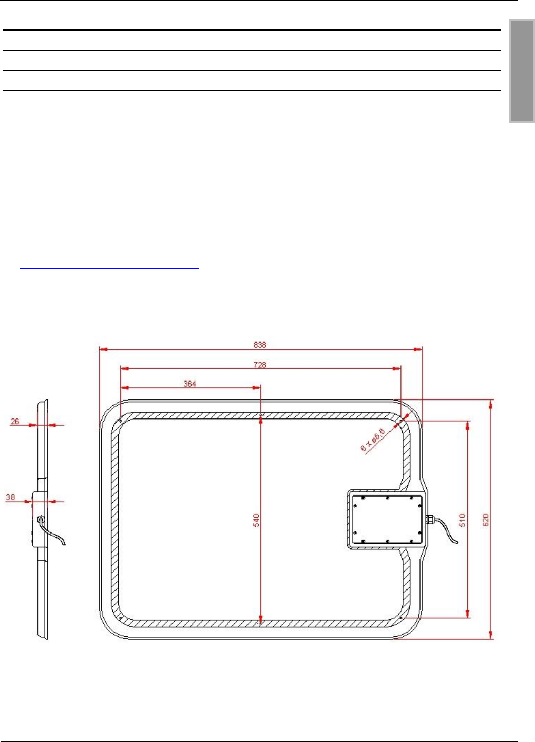
OBID i-scan®
Montage
ID ISC.ANT800/600-DA
FEIG ELECTRONIC GmbH
Seite 7 von 42
M50101-2de-ID-B.doc
D E U T S C H
3 Montage und Anschluss
3.1 Montage des Gehäuses
Die Antenne ID ISC.ANT800/600-DA ist für die Montage an Halterungen aus nicht leitenden Mate-
rialien (z.B. Kunststoff oder Holz) sowohl für den Innen- wie auch den Außenbereich konzipiert. Zur
Befestigung der Antenne befinden sich im Innenbereich der Antenne 6 Bohrungen (d=5,4 mm, s.
Bild 1). Zur Montage empfehlen wir eine 5 mm Holzschraube (DIN 96) oder eine Maschinen-
schraube (DIN 7985) mit einem Kopfdurchmesser von mindestens 10 mm bis maximal 12 mm.
Das maximale Anzugsmoment für freidrehende Schrauben beträgt 2,0 Nm.
Reichen die vorhandenen Bohrungen nicht aus, können innerhalb des schraffierten Bereichs, wei-
tere Löcher (d=5,4 mm) gebohrt werden.
Nur wenn Veränderungen der Voreinstellung am Antennen Tuner ID ISC.DAT notwendig sind
(s. 4.3 Einstellung des Antennentuners), muss der Gehäusedeckel entfernt werden. Das Anzugs-
moment der Deckelschrauben beim Verschließen der Antenne beträgt 0,25 Nm.
Bild 1: Montagezeichnung ID ISC.ANT800/600-DA (alle Maße in mm)
Hinweis: Die Antenne muss einen Mindestabstand von 10 cm von Metallteilen haben! Schon
ab 50 cm Abstand zu Metallteilen muss mit Einbußen in der Lesereichweite ge-
rechnet werden.
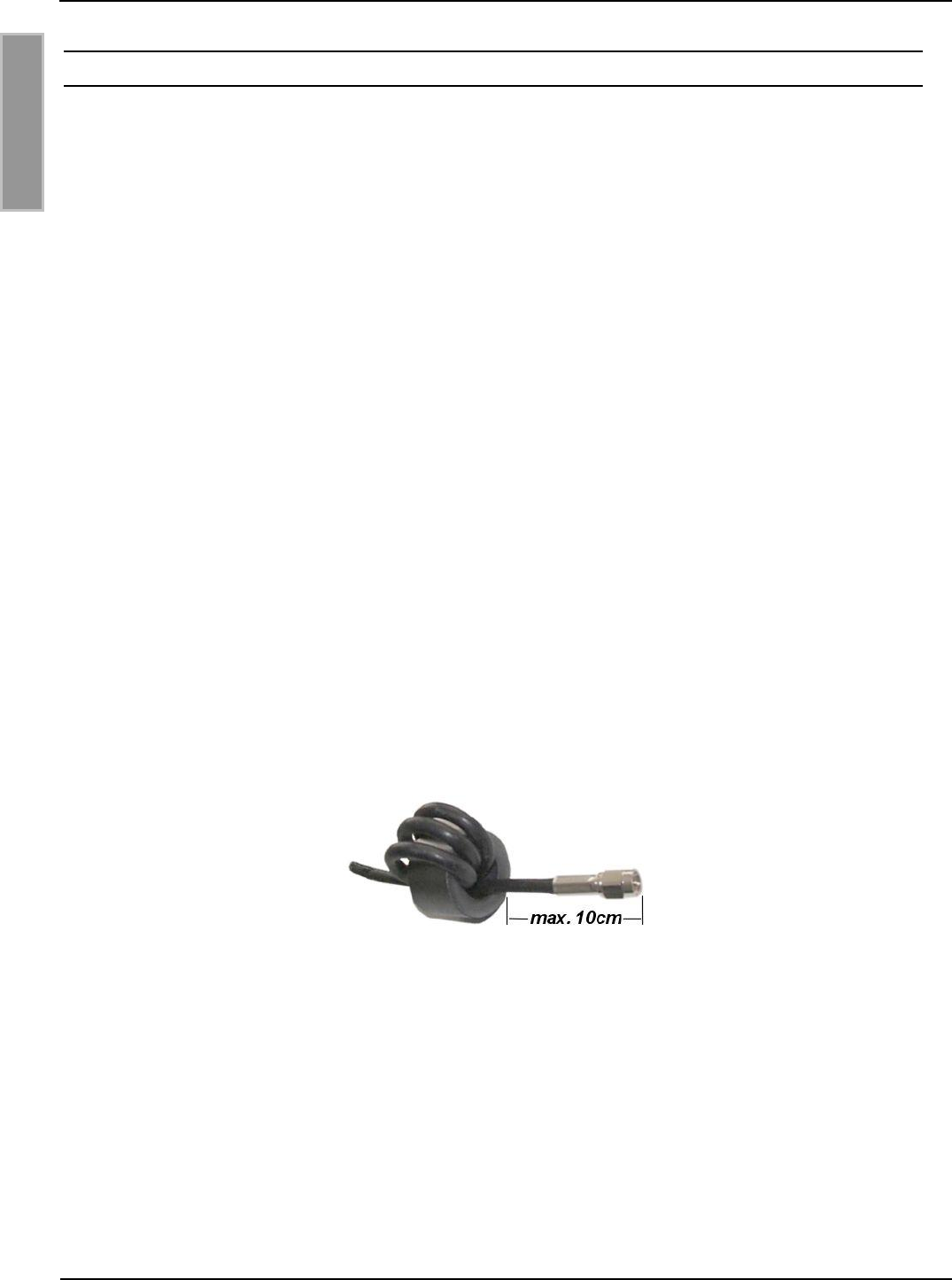
OBID i-scan®
Montage
ID ISC.ANT800/600-DA
FEIG ELECTRONIC GmbH
Seite 8 von 42
M50101-2de-ID-B.doc
D E U T S C H
3.2 Hinweise zur Kabelführung der Antennenzuleitung
Bei der Kabelführung bzw. beim Aufbau von Einzelantennen oder Antennen Gates ist auf folgen-
des zu achten:
Das Antennenkabel ist immer vor dem Abgleichen fest zu verlegen.
Bis zu einem Abstand von 50 cm sollte das Antennenkabel immer senkrecht von der Antenne
weg geführt werden.
Muss das Antennenkabel näher an der Antenne entlang verlegt werden, so sind mindestens
20 cm Abstand einzuhalten.
Ein Verlegen des Antennenkabel durch die Antenne ist immer ungünstig.
Um optimale Lesereichweiten zu erzielen sollte das Antennenanschlusskabel nicht verkürzt
oder verlängert werden. Ist eine Verlängerung zwingend erforderlich, so kann dies mit einem
50 Kabel in der Länge /2 (ID ISC.ANT.EC Extension Cable, halbe Wellenlänge bei 13,56
MHz, RG58=7,20 m) durchgeführt werden. Dabei ist mit geringen Empfindlichkeitsverlusten zu
rechnen.
Das Antennenkabel muss einen Abstand von wenigstens 30 cm zu parallel geführten stromfüh-
renden Leitungen haben.
Um mögliche Störungen zu unterdrücken, sollten in alle Anschlusskabel der Antennen und des
Power Splitters je ein EMV-Ringkern da=28 mm eingebaut werden. Dafür ist das Koaxialkabel
mindestens vier mal, eng anliegend durch den EMV-Ringkern zu schleifen. Der Abstand zwischen
Readeranschluss und Ringkern sollte dabei maximal 10 cm betragen.
Bild 2: Montage EMV-Ringkern auf Anschlusskabel

OBID i-scan®
Montage
ID ISC.ANT800/600-DA
FEIG ELECTRONIC GmbH
Seite 9 von 42
M50101-2de-ID-B.doc
D E U T S C H
4 Inbetriebnahme
Die Inbetriebnahme der Antenne ID ISC.ANT800/600-DA wird an Hand einer einfachen Konfigura-
tion aus einem Reader und einer Antenne erläutert. Zum Abgleichen der Antenne wird eine DC-
Spannungsversorgung für den Antennentuner benötigt.
Die Spannungsversorgung als auch die HF Signale werden über das Koaxialkabel eingespeist.
Der im Beispiel verwendete Reader ID ISC.LR2500 verfügt über die Möglichkeit, eine Antenne mit
DC - Spannung zu versorgen.
Weitere Möglichkeiten zur Spannungsversorgung eines Antennentuners ID ISC.DAT können der
entsprechenden Montageanleitung (M40401-xde-ID-B) entnommen werden.
4.1 Benötigte Komponenten
Folgende Komponenten werden für den oben beschriebenen Aufbau benötigt:
- Reader ID ISC.LR2500-A Long Range Reader
- Antenne ID ISC.ANT800/600-DA Base Antenna
Die Kabel an der Antenne ID ISC.ANT800/600-DA ist ca. 3,60m lang. Um eine optimale
Lesereichweite, bei Aufbauten mit einer Antenne und einem Leser ID ISC.LR2500, zu erzielen
sollte das Kabel gegen ein 1,35m Kabel ausgetauscht werden. In diesem Fall wird zusätzlich
benötigt:
- ID ISC. ANTC135 Antenna cable 1,35m
Bei größeren Abständen zwischen Reader und Antennen kann mit der Verlängerung
ID ISC.ANT.EC das Antennenkabel um 7,20m Kabel verlängert werden.
Dies führt allerdings zu geringen Leistungseinbusen.
Zur Kabelverlängerung wird benötigt:
- ID ISC.ANT.EC Extension Cable
Zur Inbetriebnahme wird die Servicesoftware
- ISOStart ab Version 9.01
auf einem Personal Computer mit Microsoft® Windows® Betriebssystem benötigt. Die
Servicesoftware ist auf dem Download Bereich der Firma FEIG ELECTRONIC GmbH unter
www.feig.de zu finden.
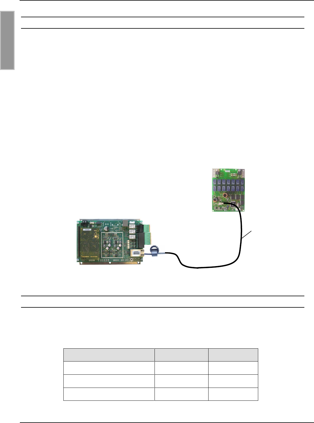
OBID i-scan®
Montage
ID ISC.ANT800/600-DA
FEIG ELECTRONIC GmbH
Seite 10 von 42
M50101-2de-ID-B.doc
D E U T S C H
4.2 Aufbau der Antenne
Die einzelnen Komponenten sind wie in
Bild 3 aufzubauen.
Bild 3 Aufbau der Konfiguration
4.3 Einstellung des Antennentuners
Die Antennen ID ISC.ANT800/600-DA werden ab Werk mit folgender Einstellung der Jumper aus-
geliefert. Die Einstellung sind für die Antenne zu überprüfen.
Tabelle 1: Jumperstellung Abgleichplatinen
Funktion
Jumper
Position
1 Gütewiderstand
JP1
geschlossen
2 Gütewiderstand
JP2
offen
Antennenschalter
JP3
geschlossen
X6
ANT1
X3
1,35m
Abgleichplatine der
Antenne ID ISC.ANT800/600-DA
Ringkern
Long Range Reader
ID ISC.LR2500
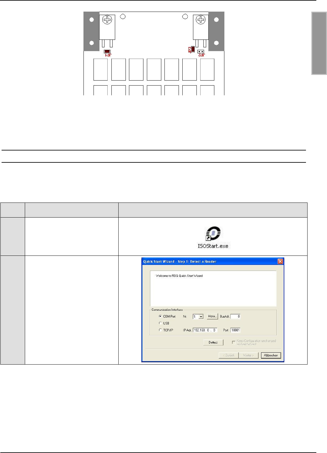
OBID i-scan®
Montage
ID ISC.ANT800/600-DA
FEIG ELECTRONIC GmbH
Seite 11 von 42
M50101-2de-ID-B.doc
D E U T S C H
Hinweis: Siehe hierzu auch die Montageanleitung des dynamischen Antennentuners
ID ISC.DAT (M40401-xde-ID-B).
4.4 Abgleich der Antenne
Zum Abgleichen der Antenne ist die Software ISOStart zu öffnen und zunächst die aktuelle Konfi-
guration des Reader auszulesen:
Step
Vorgang
Hinweis
1
ISOStart Software starten
2
„Detect“ ausführen...
OBID i-scan®
Montage
ID ISC.ANT800/600-DA
FEIG ELECTRONIC GmbH
Seite 12 von 42
M50101-2de-ID-B.doc
D E U T S C H
Step
Vorgang
Hinweis
3
„Run without change“
anwählen
Dies bei jedem erneuten
Öffnen des ISO-Start
auswählen , da ansonsten
die ursprüngliche
Konfiguration überschrieben
wird.
4
Options => Program
auswählen
5
Expert Mode auswählen und
mit OK bestätigen.
OBID i-scan®
Montage
ID ISC.ANT800/600-DA
FEIG ELECTRONIC GmbH
Seite 13 von 42
M50101-2de-ID-B.doc
D E U T S C H
Step
Vorgang
Hinweis
6
Logical View anwählen.
Die gewünschte Sendeleistung ist einzustellen und die Antenne abzugleichen.
Step
Vorgang
Hinweis
7
Menü „Configuration“ aus-
wählen
8
Air Interface:
“Output - Power” = 4W
„Mulitplexer enable“
abwählen
„Transponder-Driver“
wählen (hier ISO 15693)
„EnableDCPower“
anwählen
9
mit „Apply“ programmieren
OBID i-scan®
Montage
ID ISC.ANT800/600-DA
FEIG ELECTRONIC GmbH
Seite 14 von 42
M50101-2de-ID-B.doc
D E U T S C H
Step
Vorgang
Hinweis
10
Transponder:
Konfigurieren Sie die
Parameter wie folgt:
„Driver“ – hier ISO 15693
„Anticollision“ – enable
„PersistenceResetTime“
20 x 5 ms
„No of Timeslots“ – 1
timeslot
„Data Coding“ – 1 of 4
„AFI“ – Disabled
11
mit „Apply“ programmieren
12
Operating Mode:
Vor dem Abgleichen der
Antenne ist der „Host
Mode“ zu aktivieren
13
mit „Apply“ programmieren
14
Menü „Commands“
auswählen
15
„Start Tuning“ auf Tuner-
Address 1 durchführen.
Die Abgleichprozedur kann
bis zu 30s andauern.
16
Abgleichergebnis mit „Get
Antenna Values“ kontrollie-
ren.
17
Wenn Tuning Status nicht „OK“ Schritt 15 & 16 wiederholen.
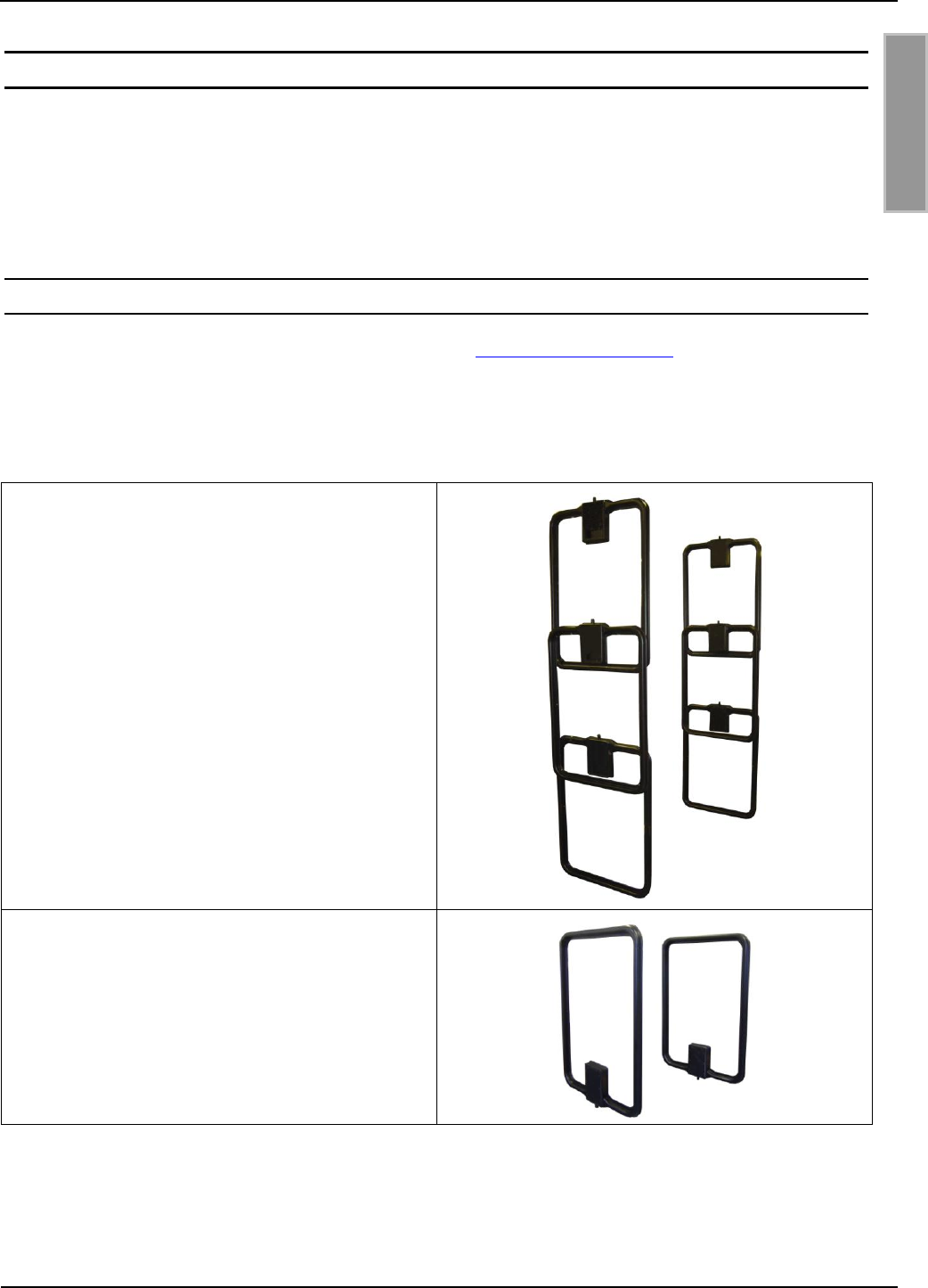
OBID i-scan®
Montage
ID ISC.ANT800/600-DA
FEIG ELECTRONIC GmbH
Seite 15 von 42
M50101-2de-ID-B.doc
D E U T S C H
5 Geräteanordnungen mit der Antenne ID ISC.ANT800/600-DA
Abhängig von der Applikation und den national geltenden Funkvorschriften sind verschiedene An-
tennenaufbauten möglich. Dabei können mehrere Antennen ID ISC.ANT800/600-DA zusammen
mit einem oder mehreren Power Splittern ID ISC.ANT.PS-B und/oder mit einem Multiplexer
ID ISC.ANT.MUX kombiniert werden.
5.1 Standard-Applikationen
Zu den Standard-Applikationen gehören neben der in Kap. 4 Inbetriebnahme beschriebenen Ein-
zelantenne auch die Antennenaufbauten, bei denen mehrere Antennen als Gate kombiniert sind.
Für die grundlegenden Kombinationen existieren Application-Notes, aus denen wieder weitere
Antennenaufbauten abgeleitet werden können. Folgende Application-Notes erhältlich:
Application-Note:
Configuring and Tuning an
Antenna Gate from four or six
ID ISC.ANT800/600-DA Antennas
(N70301-xD-ID-B)
Application-Note:
Configuring and Tuning
an Antenna Gate from
from ID ISC.ANT800/600-DA Antennas
(N70302-xD-ID-B)

OBID i-scan®
Montage
ID ISC.ANT800/600-DA
FEIG ELECTRONIC GmbH
Seite 16 von 42
M50101-2de-ID-B.doc
D E U T S C H
5.2 Funk-Regularien im EU-Raum und den USA
Die Konfiguration der RFID Leser und die maximale Sendeleistung der Antennen werden im we-
sentlichen durch die länderspezifischen Funk-Vorschriften beeinflusst. Für den gesamten EU gel-
ten einheitliche Grenzwerte nach der R&TTE Richtlinie und EN 300 330. In Nord Amerika wird dies
durch die FCC Part 15 (USA) bzw. RSS210 (Kanada) geregelt.
Die Antenne ID ISC.ANT800/600 mit dem Leser ID ISC.LRM2500-B entspricht, bei bestimmungs-
gemäßer Verwendung den grundlegenden Anforderungen des Artikels 3 und den übrigen ein-
schlägigen Bestimmungen der R&TTE Richtlinie 1999/5/EG vom März 1999. Daher ist der Betrieb
in den 27 EU-Staaten und den EFTA Staaten (EU-Staaten und Schweiz, Norwegen und Island) mit
einer maximalen Feldstärke von 42 dBµA/m in 10 m Entfernung möglich.
Eine Funkzulassung (bei einer maximalen Feldstärke von 84 dBµV/m in 30 m Entfernung) für die
Antenne ID ISC.ANT800/600 mit dem Leser ID ISC.LRM2500-B nach FCC Part 15 für die USA
und RSS 210 für Kanada wurde erteilt.
Weiterhin ist eine Funkzulassung nach der Norm EN 300 330 in allen 46 CEPT Staaten möglich.
Die CEPT Staaten sind:
Albania (ALB), Andorra (AND), Austria (AUT), Azerbaijan (AZE), Belarus (BLR), Belgium (BEL),
Bulgaria (BUL), Bosnia and Herzegovina (BIH), Croatia (HRV), Cyprus (CYP), Czech Republic
(CZE), Denmark (DNK), Estonia (EST), Finland (FIN), France (F), Germany (D), Greece (GRC),
Hungary (HNG), Iceland (ISL), Ireland (IRL), Italy (I), Latvia (LVA), Liechtenstein (LIE), Lithuania
(LTU), Luxembourg (LUX), Malta (MLT), Former Yugoslav Republic of Macedonia (MKD), Moldova
(MDA), Monaco (MCO), Netherlands (HOL), Norway (NOR), Poland (POL), Portugal (POR), Ro-
mania (ROU), Russian Federation (RUS), San Marino (SMR), Slovak Republic (SVK), Slovenia
(SVN), Spain (E), Sweden (S), Switzerland (SUI), Turkey (TUR), Ukraine (UKR), United Kingdom
(G), Vatican City (CVA) and Yugoslavia.
Es gelten folgende Einschränkungen (Stand: August 2011):
1. Außerhalb der EFTA Staaten muss in jedem Fall eine Funkzulassung beantragt werden. Die
vorhandenen Messprotokolle nach EN 300 330 sind in der Regel ausreichend.
Bei der Inbetriebnahme der Antennen ist vom Systemintegrator darauf zu achten, dass die vorge-
schriebenen Montagehinweise beachtet, die notwendigen Reader Einstellungen durchgeführt und
zulässigen Grenzwerte der nationalen Funk Vorschriften nicht überschritten werden.

OBID i-scan®
Montage
ID ISC.ANT800/600-DA
FEIG ELECTRONIC GmbH
Seite 17 von 42
M50101-2de-ID-B.doc
D E U T S C H
5.2.1 Zugelassenen Readereinstellung
Parameter
Europa
USA / Kanada
Allgemein
RF-Power – CFG 3
4 W
2 W
ISO15693 Label
RF Modulation – CFG 20
10 %
10%
Downlink RF Data coding –
CFG 4 / ISO-MODE / FAST
Normal (1/256)
Normal (1/256)
No of Timeslots - CFG 4
1 or 16 Timeslots
1 or 16 Timeslots
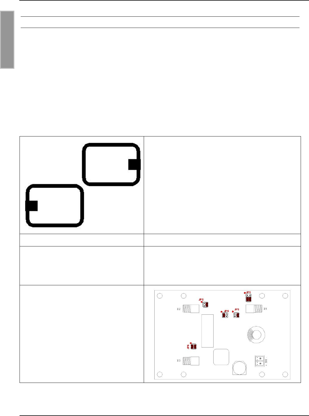
OBID i-scan®
Montage
ID ISC.ANT800/600-DA
FEIG ELECTRONIC GmbH
Seite 18 von 42
M50101-2de-ID-B.doc
D E U T S C H
5.2.2 Spezieller Antennenaufbau
Neben der Möglichkeit des Abschirmens von Antennen zum Einhalten der Regularien kann durch
spezielle Antennenaufbauten eine Kompensation des magnetischen Feldes durch entgegenge-
setzte Feldrichtungen erreicht werden. Dies wurde von FEIG ELECTRONIC GmbH für verschiede-
ne Antennenaufbauten getestet und in einem Messlabor überprüft.
Voraussetzung dafür ist, dass die Antennen exakt wie beschrieben aufgebaut werden. Die Anten-
nen müssen dabei mit einem Power Splitter ID ISC.ANT.PS verbunden werden. Um sicher zustel-
len, dass der komplette Aufbau die nationalen Funk und EMV Grenzwerte einhält, muss dies vom
Systemintegrator überprüft werden.
Der Antennenaufbau ist wie folgt durchzuführen:
Tabelle 2: Aufbau mit zwei Antennen ID ISC.ANT800/600-DA
- Die beiden Antennen müssen in einer Ebene di-
rekt nebeneinander montiert werden.
- Die beiden Tuner (Öffnungen) der Antennen müs-
sen nach außen (rechts und links) montiert werden
und in eine Richtung zeigen.
- Abstand der Antennen (Ecken) 1cm.
Readereinstellung
Maximale Sendeleistung 4W
Antennentuner
Jumperstellung am Antennentuner ID ISC.DAT
- JP1: offen
- JP2: offen
- JP3: geschlossen
Power-Splitter
mit 180° Phasendrehung
Hinweise: Abgleichen dieser Antennenkonfiguration gemäß Application-Note:
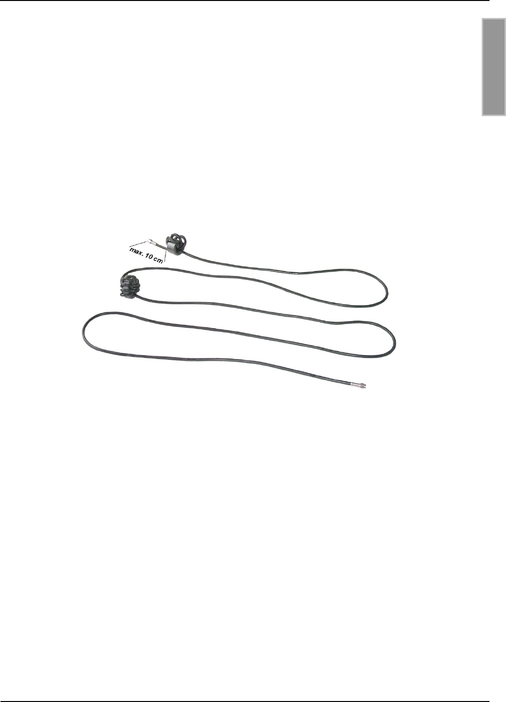
OBID i-scan®
Montage
ID ISC.ANT800/600-DA
FEIG ELECTRONIC GmbH
Seite 19 von 42
M50101-2de-ID-B.doc
D E U T S C H
Configuring and Tuning an Antenna Gate from two ID ISC.ANT800/600-DA An-
tennas (N50101-xe-ID-B).
Um die EMV Vorschriften in der USA nach FCC Part 15 einzuhalten, müssen in die Anschlusska-
bel der Antennen ID ISC.ANT800/600-DA zwei Ringkerne wie in Bild 4 skizziert eingebaut werden.
Der dem Reader beigelegte EMV-Ringkern 28 mm x 20 mm ist am Anfang des Kabels einzu-
bauen. Dafür ist die Antennenzuleitung mindestens vier mal, eng anliegend durch den Ringkern zu
schleifen. Der Abstand zwischen Readeranschluss und Ringkern sollte dabei maximal 10 cm be-
tragen.
Der EMV-Ringkern 41 mm x 15 mm ist genau in der Mitte des Antennenkabels zu montieren.
Dafür ist das Koaxialkabel mindestens zehn mal, eng anliegend durch den Ringkern zu schleifen.
Dieser Ringkerne sind dem Reader beigelegt.
Bild 4: Montage zweier Ringkerne auf Koaxialkabel

OBID i-scan®
Montage
ID ISC.ANT800/600-DA
FEIG ELECTRONIC GmbH
Seite 20 von 42
M50101-2de-ID-B.doc
D E U T S C H
Technische Daten
Mechanische Daten
Gehäuse
Kunststoff ABS
Abmessungen ( B x H x T )
852 x 620 x 40 mm 1 mm
Gewicht
ca. 2,5 kg
Schutzart
IP 65
Farbe
Schwarz
Elektrische Daten
Maximale Sendeleistung
8 W
Zulässige Sendeleistung
– EU-Raum (EN 300 330)
– USA (FCC Part 15)
- Kanada (RSS-210)
4,0 W
2,0 W
2,0 W
Betriebsfrequenz
13,56 MHz
Reichweite
Maximal 100 cm*
Antennenanschluss
1 x SMA Stecker (50 )
Antennenanschlusskabel
RG58, 50 , ca. 3,60 m lang
Umgebungsbedingungen
Temperaturbereich
– Betrieb
– Lagerung
–25°C bis +55°C
–25°C bis +60°C
Vibration
EN60068-2-6
10 Hz bis 150 Hz : 0,075 mm / 1 g
Schock
EN60068-2-27
Beschleunigung : 30 g

OBID i-scan®
Montage
ID ISC.ANT800/600-DA
FEIG ELECTRONIC GmbH
Seite 21 von 42
M50101-2de-ID-B.doc
D E U T S C H
Angewendete Normen
EMV
EN 300 683
Sicherheit
– Europa
– USA
EN 60950
UL 60950 (Auf Anfrage)
*Label 46 x 75 mm2, über der Antennen Mitte, Empfindlichkeit / Minimale Feldstärke Hmin=60 mA/m
rms, parallele Ausrichtung des Labels zur Antenne. Sendeleistung 4 W.
OBID i-scan®
Montage
ID ISC.ANT800/600-DA
FEIG ELECTRONIC GmbH
Seite 22 von 42
M50101-2de-ID-B.doc
D E U T S C H
5.3 Zulassung
5.3.1 Europa (CE)
Die Funkanlage entspricht, bei bestimmungsgemäßer Verwendung den grundlegenden Anforde-
rungen des Artikels 3 und den übrigen einschlägigen Bestimmungen der R&TTE Richtlinie
1999/5/EG vom März 1999.
Equipment Classification gemäß ETSI EN 300 330 und ETSI EN 301 489: Class 2
Die technischen Daten des Readers ID ISC.LRM2500 finden Sie in der Montageanleitung.

OBID i-scan®
Montage
ID ISC.ANT800/600-DA
FEIG ELECTRONIC GmbH
Seite 23 von 42
M50101-2de-ID-B.doc
D E U T S C H
5.3.2 USA (FCC) und Kanada (IC)
Produkt Name:
ID ISC.ANT800/600-DA
Antennen Name:
ID ISC.ANT800/600-DA
Reader Name:
ID ISC.LRM2500
FCC ID:
IC:
PJMLRM2500
6633A-LRM2500
Notice for USA and
Canada
This device complies with Part 15 of the FCC Rules and with
RSS-210 of Industry Canada.
Operation is subject to the following two conditions.
(1) this device may not cause harmful interference, and
(2) this device must accept any interference received,
including interference that may cause undesired operation.
Unauthorized modifications may void the authority granted under
Federal communications Commission Rules permitting the operation
of this device.
This equipment has been tested and found to comply with the limits for
a Class A digital device, pursuant to Part 15 of the FCC Rules. These
limits are designed to provide reasonable protection against harmful
interference when the equipment is operated in a commercial
environment. This equipment generates, uses, and can radiate radio
frequency energy and, if not installed and used in accordance with the
instruction manual, may cause harmful interference to radio
communications. Operation of this equipment in a residential area is
likely to cause harmful interference in which case the user will be
required to correct the interference at his own expense.
Le présent appareil est conforme aux CNR d'Industrie Canada appli-
cables aux appareils radio exempts de licence. L'exploitation est auto-
risée aux deux conditions suivantes :
(1) l'appareil ne doit pas produire de brouillage, et
(2) l'utilisateur de l'appareil doit accepter tout brouillage radioélectrique
subi, même si le brouillage est susceptible d'en compromettre le fonc-
tionnement.
Die technischen Daten des Readers ID ISC.LRM2500 finden Sie in der Montageanleitung.
6 Lieferumfang:
Folgende Komponenten sind im Lieferumfang enthalten:
- Antenne ID ISC.ANT800/600-DA

OBID i-scan®
Installation
ID ISC.ANT800/600-DA
FEIG ELECTRONIC GmbH
Page 24 of 42
M50101-2de-ID-B.doc
E N G L I S H
Note
Copyright 2005-2012 by
FEIG ELECTRONIC GmbH
Lange Strasse 4
D-35781 Weilburg-Waldhausen
Tel.: +49 6471 3109-0
http://www.feig.de
With the edition of this document, all previous editions become void. Indications made in this manual may be
changed without previous notice.
Copying of this document, and giving it to others and the use or communication of the contents thereof are
forbidden without express authority. Offenders are liable to the payment of damages. All rights are reserved
in the event of the grant of a patent or the registration of a utility model or design.
Composition of the information in this manual has been done to the best of our knowledge. FEIG
ELECTRONIC GmbH does not guarantee the correctness and completeness of the details given in this
manual and may not be held liable for damages ensuing from incorrect or incomplete information. Since,
despite all our efforts, errors may not be completely avoided, we are always grateful for your useful tips.
The installation instructions given in this manual are based on advantageous boundary conditions. FEIG
ELECTRONIC GmbH does not give any guarantee promise for perfect function in cross environments.
FEIG ELECTRONIC GmbH assumes no responsibility for the use of any information contained in this
manual and makes no representation that they free of patent infringement. FEIG ELECTRONIC GmbH does
not convey any license under its patent rights nor the rights of others.
OBID® and OBID i-scan® are registered trademarks of FEIG ELECTRONIC GmbH.
Microsoft® und Windows® is a registered trademark of Microsoft Corporation

OBID i-scan®
Installation
ID ISC.ANT800/600-DA
FEIG ELECTRONIC GmbH
Page 25 of 42
M50101-2de-ID-B.doc
E N G L I S H
Contents
7 Safety and warning notes – READ BEFORE STARTUP 26
8 Performance features of the ID ISC.ANT800/600-DA Antenna 27
9 Installation and wiring 28
9.1 Installing the housing ............................................................................................... 28
9.2 Notes on routing the antenna cable ........................................................................ 29
10 Startup 30
10.1 Required components .............................................................................................. 30
10.2 Constructing the antenna......................................................................................... 31
10.3 Setting the antenna tuner ......................................................................................... 31
10.4 Tuning the antenna ................................................................................................... 32
11 Device arrangements with the ID ISC.ANT800/600-DA antenna 35
11.1 Standard applications .............................................................................................. 35
11.2 RF regulations in EU countries and the USA .......................................................... 36
11.2.1 Permissible Reader settings ................................................................................... 37
11.2.2 Special antenna construction ................................................................................. 38
Technical Data 40
11.3 Approval .................................................................................................................... 41
11.3.1 Europe (CE) ........................................................................................................... 41
11.3.2 USA (FCC) and Canada (IC) .................................................................................. 42
12 Scope of delivery: 42

OBID i-scan®
Installation
ID ISC.ANT800/600-DA
FEIG ELECTRONIC GmbH
Page 26 of 42
M50101-2de-ID-B.doc
E N G L I S H
7 Safety and warning notes – READ BEFORE STARTUP
The device may be used only for the purpose intended by the manufacturer.
This manual should be kept in an accessible location and distributed to each user.
Unauthorized modifications and the use of replacement parts and ancillary equipment not
purchased from or recommended by the manufacturer may result in fire, electric shock and
injury. Such actions will void the warranty and the manufacturer will not be held liable for any
consequences.
The device is covered under the warranty terms of the manufacturer in their iteration at the time
of purchase. No liability is assumed for unsuitable, incorrect manual or automatic setting of
parameters for a device or for inappropriate use of a device.
Repairs are to be performed solely by the manufacturer.
Wiring, startup, maintenance or other work on the device are to be performed only by electricial
technicians having the relevant training and education.
Before opening the device, always turn off power and use a meter to ensure that the device is
in fact not receiving power. The extinguishing of a power LED is not a reliable indicator that the
device is separated from the mains and is safe to work on.
All work on the device including its installation must conform with national electrical regulations
and local code.
When working on the devices, always refer to the relevant safety regulations.
When performing work on a device which has been opened, note that voltages of up to 1000V
may be present on the components.
When performing work on a device which has been opened, note that some components may
become extremely hot. Risk of burn injury !
Special note for persons wearing heart pacemakers:
Although this device does not exceed the permissible limits for electromagnetic fields, you should
keep a minimum distance of 25 cm between the device and your pacemaker, and not remain in the
direct vicinity of the device or antenna for longer periods of time.

OBID i-scan®
Installation
ID ISC.ANT800/600-DA
FEIG ELECTRONIC GmbH
Page 27 of 42
M50101-2de-ID-B.doc
E N G L I S H
8 Performance features of the ID ISC.ANT800/600-DA Antenna
The ID ISC.ANT800/600-DA antenna is a single loop antenna with tuning circuitry and has been
optimized as a sending and receiving antenna for the ID ISC.LR2500 Reader. With a set
transmitting power of 4 W a read range of up to 100 cm is possible. Operation with other Readers
having a transmitting frequency of 13.56 MHz and an output impedance of 50 is likewise
possible.
The antenna consists of the electrical antenna conductor, housing and the tuning circuitry
ID.ISC.DAT (Tuner).
The antenna was factory tuned on a wood base to an impedance of 50 . After installing in other
ambient conditions, the antenna can be tuned using the corresponding commands (see Manual
Communication FU, H30701-xe-ID-B).
The antenna can be used for detecting either goods or persons. It is suitable for indoor or outdoor
installation.
The preferred orientation of a Smart Label is parallel to the antenna area. The maximum range is
achieved over the center of the antenna area.
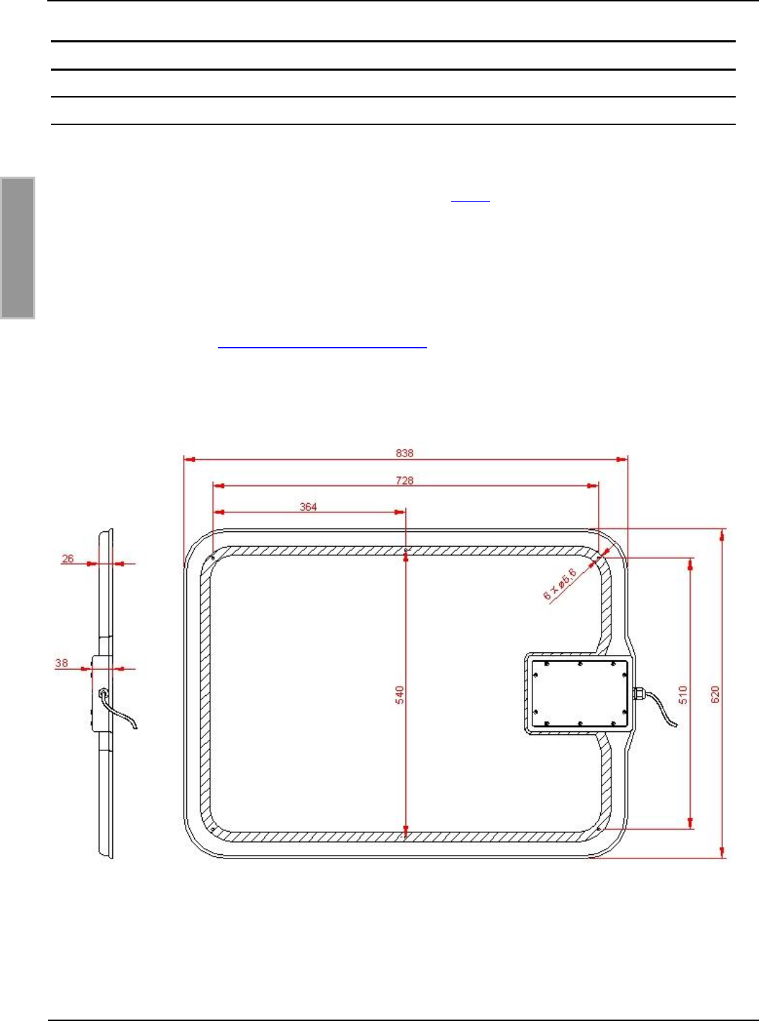
OBID i-scan®
Installation
ID ISC.ANT800/600-DA
FEIG ELECTRONIC GmbH
Page 28 of 42
M50101-2de-ID-B.doc
E N G L I S H
9 Installation and wiring
9.1 Installing the housing
The ID ISC.ANT800/600-DA antenna is designed for installation on holders made of non-
conducting materials (e.g. plastic or wood) either indoors or outdoors. 6 mounting holes are
provided inside the antenna for attaching (d=5.4 mm, see Fig. 5). We recommend use of a 5 mm
wood screw (DIN 96) or a machine screw (DIN 7985) having a head diameter of at least 10 mm up
to a maximum of 12 mm. The maximum tightening torque for free-turning screws is 2.0 Nm.
If the existing holes are not sufficient, additional holes (d=5.4 mm) can be drilled inside the hatched
area.
The housing cover only needs to be removed when making changes to the factory setting on the
ID ISC.DAT Tuner (see 10.3 Setting the antenna tuner), the tightening torque for the cover screws
when closing up the antenna is 0.2 Nm – 0.25 Nm.
Fig. 5: Installation drawing for ID ISC.ANT800/600-DA (all dimensions in mm)
Note: The antenna must be kept a minimum of 10 cm away from metal parts! Even at
distances of 50 cm or closer a sacrifice in reading range must be anticipated.
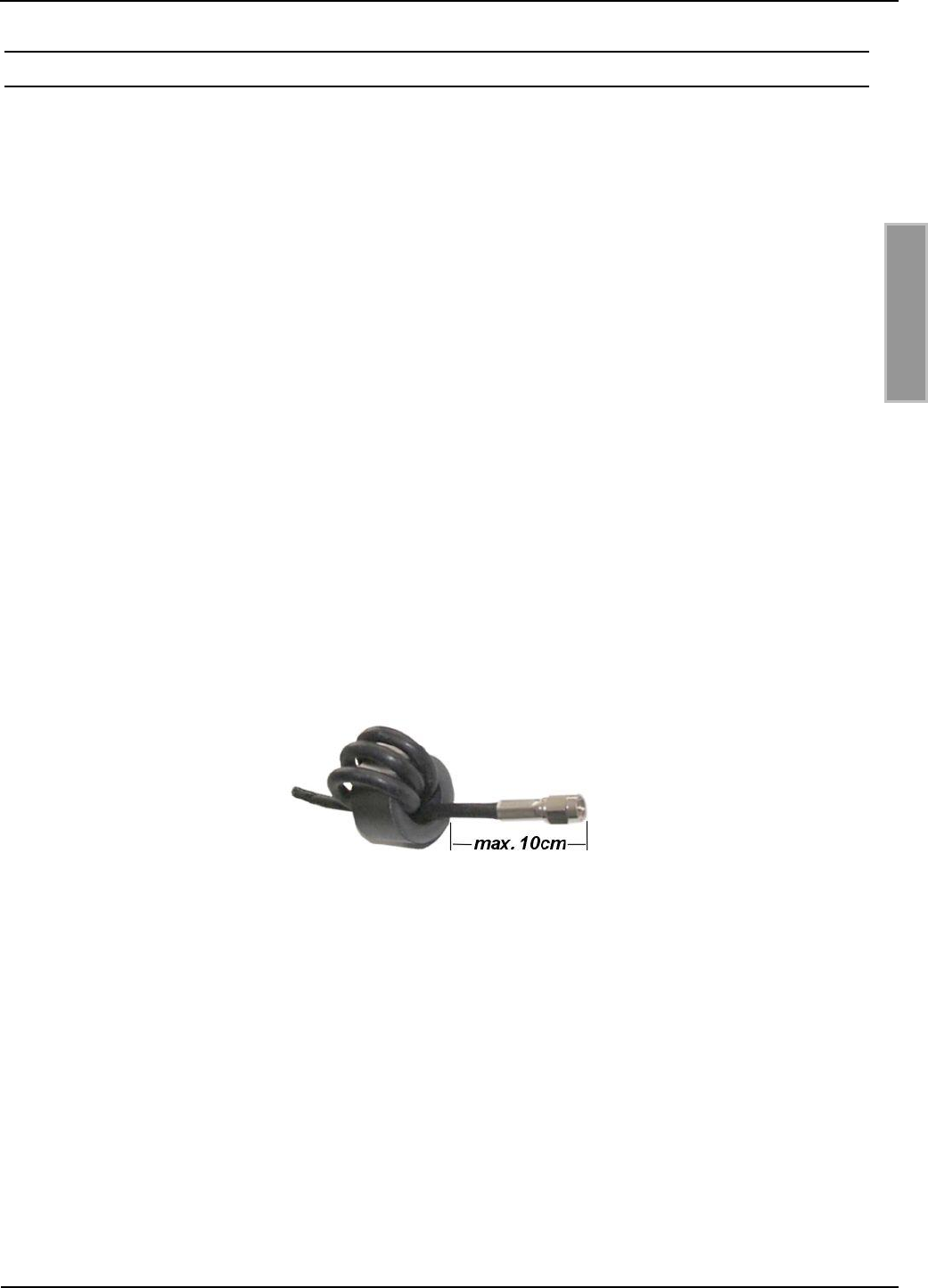
OBID i-scan®
Installation
ID ISC.ANT800/600-DA
FEIG ELECTRONIC GmbH
Page 29 of 42
M50101-2de-ID-B.doc
E N G L I S H
9.2 Notes on routing the antenna cable
Note the following when routing the cable and constructing individual antennas or antenna gates:
The antenna cable must always be routed in place before tuning.
Up to a distance of 50 cm the antenna cable should always be routed vertically away from the
antenna.
If the cable needs to be routed closer along the antenna, keep a distance of at least 20 cm.
Routing the antenna cable through the antenna itself is always detrimental.
To achieve optimum read ranges, the antenna cable should not be shortened or extended. If an
extension is absolutely necessary, this can be done using a 50 cable of length /2 (ID
ISC.ANT.EC Extension Cable, half-wavelength at 13.56 MHz, RG58=7.20 m). A slight loss of
sensitivity must then be taken into account.
The antenna cable must be kept a distance of at least 30 cm from parallel routed current-
carrying cables.
To suppress possible interference, an EMC ring core with an O.D. of 28 mm should be installed in
all antenna cables and the power splitter. Wind the coax cable at least four times tightly through
the EMC ring core as shown in the illustration. The distance between the Reader connection and
the ring core should be a maximum of 10 cm.
Fig. 6: EMC ring core installed on an antenna cable

OBID i-scan®
Installation
ID ISC.ANT800/600-DA
FEIG ELECTRONIC GmbH
Page 30 of 42
M50101-2de-ID-B.doc
E N G L I S H
10 Startup
The ID ISC.ANT800/600-DA is placed in service using a simple configuration consisting of a
Reader and an antenna. To tune the antenna a DC voltage supply is needed for the antenna tuner.
The supply voltage as well as the HF signals are carried on the coax cable.
The ID ISC.LR2500 Reader used in the example is able to provide an antenna with DC voltage.
Other ways of powering an ID ISC.DAT antenna tuner can be found in the corresponding
installation guide (M40401-xde-ID-B).
10.1 Required components
The following components are needed for the configuration described above:
- Reader ID ISC.LR2500 Type -A or -B
- Antenna ID ISC.ANT800/600-DA
The cables on the ID ISC.ANT800/600-DA antenna are each approx. 3,60m long.
To get the optimal performance at the setup with one antenna and one Reader ID ISC.LR2500 the
antenna cable should be changed to a 1,35m cable. So you need:
- ID ISC. ANTC135 Antenna cable 1,35m
For longer distances between Reader and antennas the ID ISC.ANT.EC extension can be used to
extend the antenna cable by 7.20m. This will result in slight loss of sensitivity.
For extending the cable you will need:
- ID ISC.ANT.EC
For startup the service software
- ISOStart Version 9.01 or higher
on a personal computer running under Microsoft® Windows® is required. The service can be
downloaded at the Download Area of the Homepage www.feig.de.
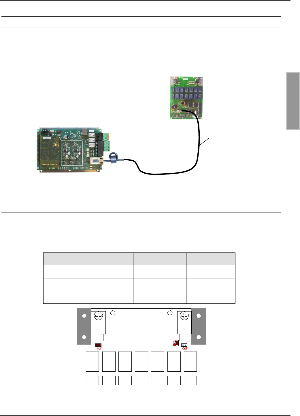
OBID i-scan®
Installation
ID ISC.ANT800/600-DA
FEIG ELECTRONIC GmbH
Page 31 of 42
M50101-2de-ID-B.doc
E N G L I S H
10.2 Constructing the antenna
The individual components are constructed as shown in Fig. 7: Antenna configuration
Fig. 7: Antenna configuration
10.3 Setting the antenna tuner
The jumpers on the ID ISC.ANT800/600-DA antennas are factory set as shown below. The
settings should be verified for each antenna.
Table 3: Jumper settings on the tuner boards
Function
Jumper
Position
1 Q-resistance
JP1
closed
2 Q-resistance
JP2
open
Antenna switch
JP3
closed
Note: See also the installation guide for the ID ISC.DAT (M40401-xde-ID-B)
X6
ANT1
X3
1,35m
Tunning board of the
antenna ID ISC.ANT800/600-DA
torrid
Long Range Reader
ID ISC.LR2500
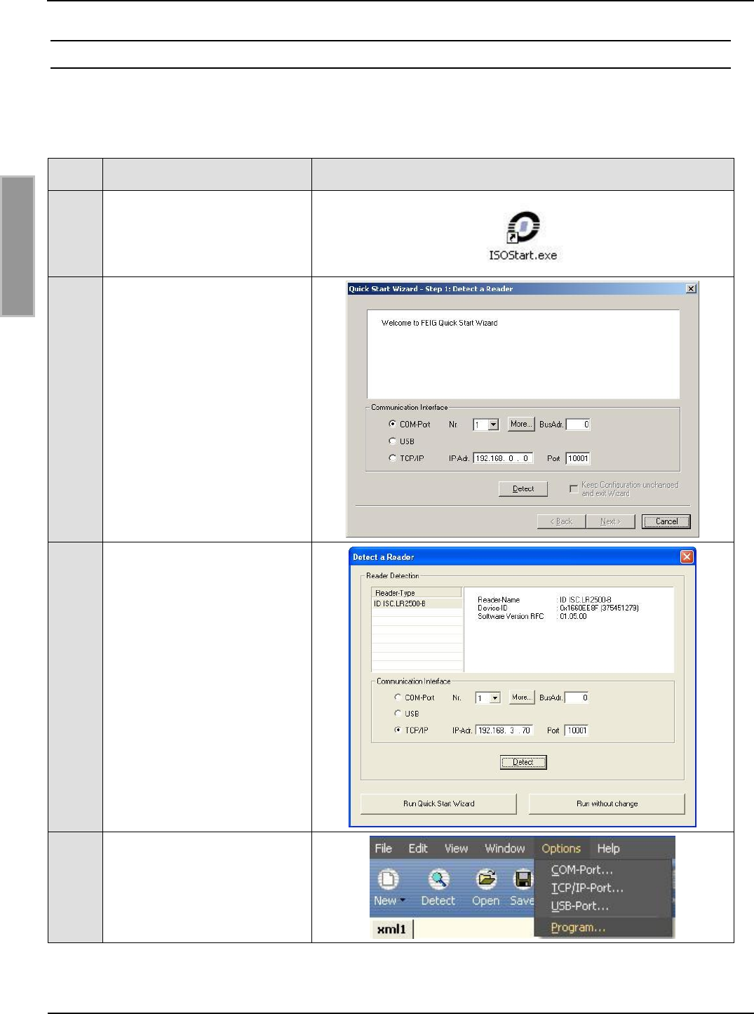
OBID i-scan®
Installation
ID ISC.ANT800/600-DA
FEIG ELECTRONIC GmbH
Page 32 of 42
M50101-2de-ID-B.doc
E N G L I S H
10.4 Tuning the antenna
To tune the antenna, open the ISOStart software and first read out the current Reader
configuration:
Step
Action
Note
1
Start ISO Start Software
2
Select „Detect“
3
Select „Run without change“
Note:
This has to be done at each
start of ISO-Start program
otherwise the configuration
of the reader will be changed
by the wizard.
4
Select „Options => Program“
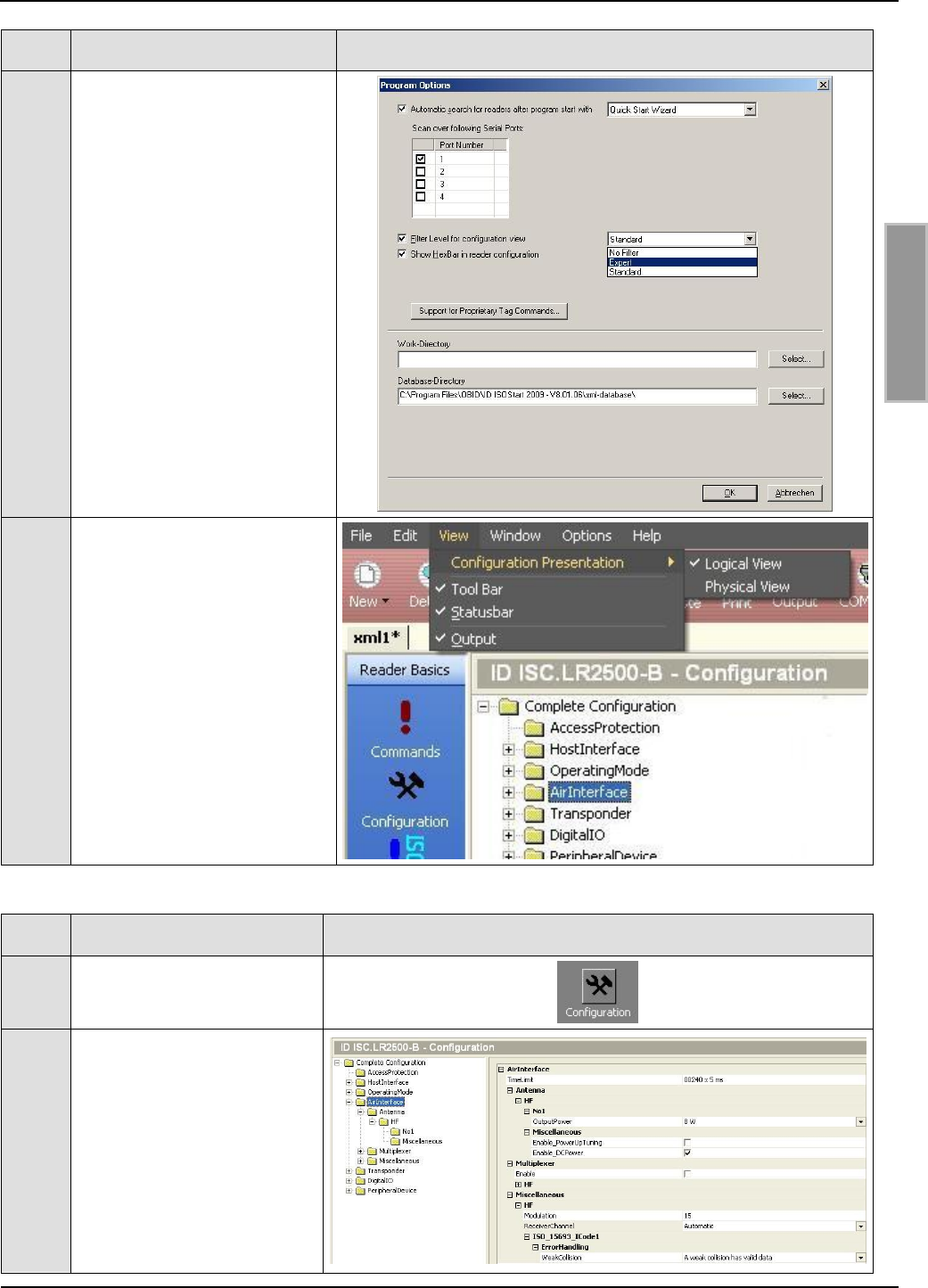
OBID i-scan®
Installation
ID ISC.ANT800/600-DA
FEIG ELECTRONIC GmbH
Page 33 of 42
M50101-2de-ID-B.doc
E N G L I S H
Step
Action
Note
5
Select „Expert Mode“ and
confirm with OK.
6
Select “Logical View”
Now set the desired RF power and tune the antenna.
Step
Procedure
Note
7
Select „Configuration“
8
Air Interface:
“Output - Power” = 4W
Deselect: „Mulitplexer
enable“
Select: „Transponder-
Driver“ (here ISO 15693)
Select: „EnableDCPower“
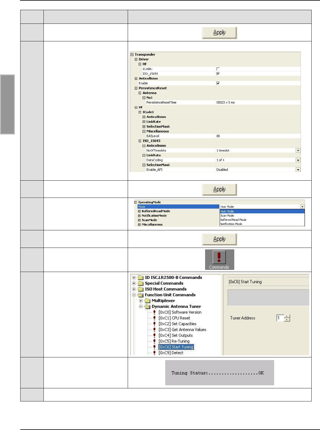
OBID i-scan®
Installation
ID ISC.ANT800/600-DA
FEIG ELECTRONIC GmbH
Page 34 of 42
M50101-2de-ID-B.doc
E N G L I S H
Step
Procedure
Note
9
Set by clicking on „Apply“.
10
Transponder:
Configure the parameter as
following:
„Driver“ Select: ISO 15693
Enable: „Anticollision“
„PersistenceResetTime“
20 x 5 ms
„No of Timeslots“ –
1 timeslot
„Data Coding“ – 1 of 4
„AFI“ – Disabled
11
Set by clicking on „Apply“.
12
Operating Mode:
To tune, activate „ISO-Host
Mode“
13
Set by clicking on „Apply“.
14
Select „Commands“ menu
15
Select „Start Tuning“ for
Tuner Address 1.
The tuning procedure may
take up to 30s.
16
Check tuning results by
using „Get Antenna
Values“.
17
If Tuning Status is not „OK“ repeat Step 15 & 16.
OBID i-scan®
Installation
ID ISC.ANT800/600-DA
FEIG ELECTRONIC GmbH
Page 35 of 42
M50101-2de-ID-B.doc
E N G L I S H
11 Device arrangements with the ID ISC.ANT800/600-DA antenna
Depending on the application and the RF regulations applicable in your country, various antenna
configurations are possible. Multiple ID ISC.ANT800/600-DA antennas can be combined together
with one or more ID ISC.ANT.PS-B power splitters and/or an ID ISC.ANT.MUX multiplexer.
11.1 Standard applications
Standard applications include, in addition to the individual antenna described in Section
10. Startup, antenna configurations in which multiple antennas are combined into a gate. There are
Application Notes for the basic combinations, which in turn can be used to derive additional
antenna configurations. The following Application Notes are available:
Application-Note:
Configuring and Tuning an
Antenna Gate from four or six
ID ISC.ANT800/600-DA Antennas
(N70301-xe-ID-B)
Application-Note:
Configuring and Tuning
an Antenna Gate from
from ID ISC.ANT800/600-DA Antennas
(N70302-xe-ID-B)

OBID i-scan®
Installation
ID ISC.ANT800/600-DA
FEIG ELECTRONIC GmbH
Page 36 of 42
M50101-2de-ID-B.doc
E N G L I S H
11.2 RF regulations in EU countries and the USA
Configuration of the RFID readers and the maximum transmitting power of the antennas are
affected mainly by the country-specific RF regulations. For the entire EU the limits are set forth in
the R&TTE Directive and EN 300 330. In North America this is regulated by FCC Part 15 (USA)
and by the RSS-210 (Canada).
The ID ISC.ANT800/600 antenna with the ID ISC.LRM2500 Reader, when used as intended,
complies with the basic requirements of Article 3 and the other relevant clauses of the R&TTE
Directive 1999/5/EG of March 1999. This means that operation in the 27 EU countries and the
EFTA countries (EU countries plus Switzerland, Norway and Iceland) is possible with a maximum
field strength of 42 dBµA/m at 10 m distance.
RF approval (at a maximum field strength of 84 dBµV/m at 30 m) for the ID ISC.ANT800/600
antenna with ID ISC.LRM2500 Reader has been granted in accordance with FCC Part 15 for the
USA and the RSS-210 for Canada
RF approval in accordance with EN 300 330 is still possible in all 46 CEPT countries.
The CEPT countries are:
Albania (ALB), Andorra (AND), Austria (AUT), Azerbaijan (AZE), Belarus (BLR), Belgium (BEL),
Bulgaria (BUL), Bosnia and Herzegovina (BIH), Croatia (HRV), Cyprus (CYP), Czech Republic
(CZE), Denmark (DNK), Estonia (EST), Finland (FIN), France (F), Germany (D), Greece (GRC),
Hungary (HNG), Iceland (ISL), Ireland (IRL), Italy (I), Latvia (LVA), Liechtenstein (LIE), Lithuania
(LTU), Luxembourg (LUX), Malta (MLT), Former Yugoslav Republic of Macedonia (MKD), Moldova
(MDA), Monaco (MCO), Netherlands (HOL), Norway (NOR), Poland (POL), Portugal (POR),
Romania (ROU), Russian Federation (RUS), San Marino (SMR), Slovak Republic (SVK), Slovenia
(SVN), Spain (E), Sweden (S), Switzerland (SUI), Turkey (TUR), Ukraine (UKR), United Kingdom
(G), Vatican City (CVA) and Yugoslavia.
The following restrictions are in effect (as of: August 2011):
Outside the EU and EFTA countries RF approval must in all cases be applied for. The existing
measuring protocols in accordance with EN 300 330 are generally sufficient.
When starting up, the system integrator should ensure that the prescribed installation instructions
are followed, the necessary Reader settings are performed and the allowed limits of the national
RF regulations are not exceeded.

OBID i-scan®
Installation
ID ISC.ANT800/600-DA
FEIG ELECTRONIC GmbH
Page 37 of 42
M50101-2de-ID-B.doc
E N G L I S H
11.2.1 Permissible Reader settings
Parameter
Europe
USA / Canada
General
RF-Power – CFG 3
4 W
2 W
ISO15693 Label
RF Modulation – CFG 20
10 %
10%
Downlink RF Data coding –
CFG 4 / ISO-MODE / FAST
Normal (1/256)
Normal (1/256)
No of Timeslots - CFG 4
1 or 16 Timeslots
1 or 16 Timeslots
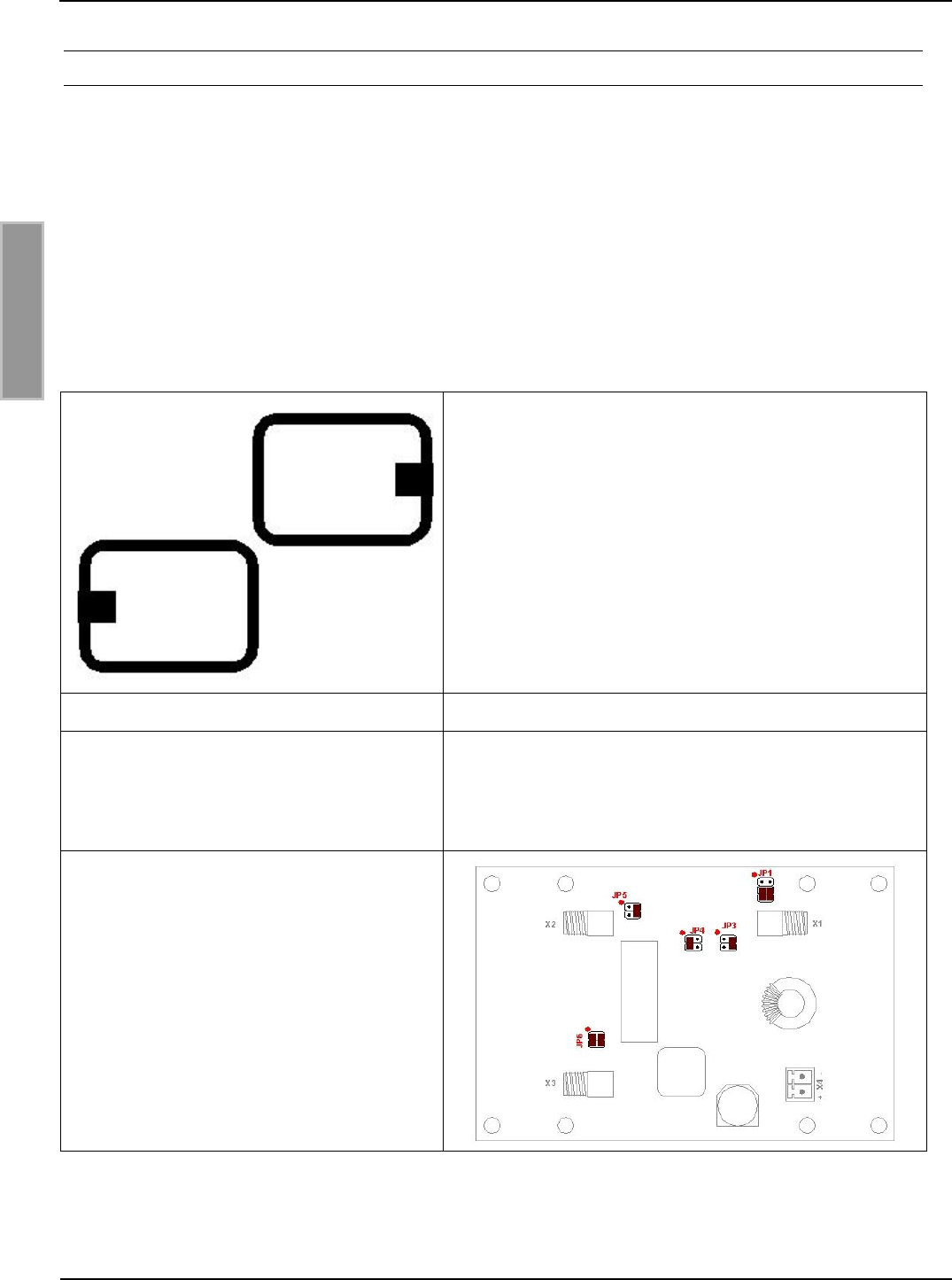
OBID i-scan®
Installation
ID ISC.ANT800/600-DA
FEIG ELECTRONIC GmbH
Page 38 of 42
M50101-2de-ID-B.doc
E N G L I S H
11.2.2 Special antenna construction
In addition to shielding the antennas to conform with national regulations, special antenna
constructions can be used to achieve compensation of the magnetic field by means of opposing
field directions. This has been tested by FEIG ELECTRONIC GmbH for various antenna
constructions and verified in a testing laboratory.
The prerequisite for this is that the antennas be constructed exactly as described. The antennas
must be connected to an ID ISC.ANT.PS Power Splitter. To ensure that the complete system stays
within the national RF and EMC limits, this must be verified by the system integrator.
Construct the antennas as follows:
Table 4: Construction with two ID ISC.ANT800/600-DA antennas
- The two antennas must be mounted directly next
to each other and in the same plane
- The two tuners (openings) of the antennas must
face out (right and left) and point in one direction.
- Antenna separation (corners) 1cm.
Reader setting
Maximum RF power 4W
Antenna tuner
Jumper settings on ID ISC.DAT antenna tuner
- JP1: open
- JP2: open
- JP3: closed
Power Splitter
with 180° phase rotation
Notes: Tuning this antenna configuration according to the Application Note:
Configuring and Tuning an Antenna Gate from two ID ISC.ANT800/600-DA
Antennas (N50101-xe-ID-B).
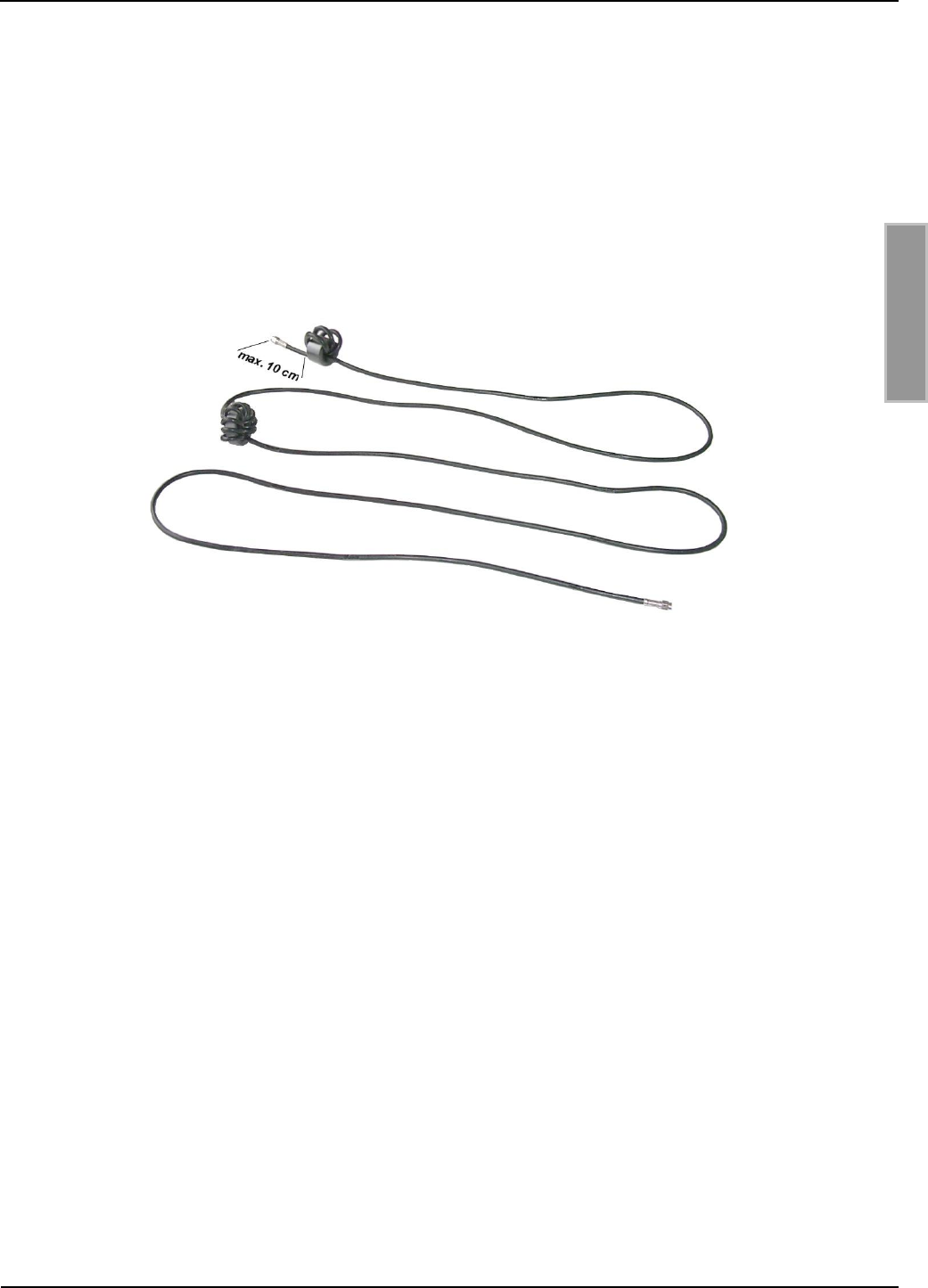
OBID i-scan®
Installation
ID ISC.ANT800/600-DA
FEIG ELECTRONIC GmbH
Page 39 of 42
M50101-2de-ID-B.doc
E N G L I S H
To maintain the EMC requirements in the USA as per FCC Part 15, two ring cores must be
installed in the cables for the ID ISC.ANT800/600-DA antennas as shown in Fig. 8.
The EMC ring core supplied with the Reader, 28 mm x 20 mm, is installed at the front end of the
cable. Wind the antenna cable at least four times tightly around the ring core. The distance
between the Reader connection and the ring core should be at least 10 cm.
The 41 mm x 15 mm EMC ring core is installed exactly in the middle of the antenna cable. Wind
the coax cable at least 10 times tightly around the ring core. These ring cores are included with the
Reader.
Fig. 8: Installing two ring cores on coaxial cable

OBID i-scan®
Installation
ID ISC.ANT800/600-DA
FEIG ELECTRONIC GmbH
Page 40 of 42
M50101-2de-ID-B.doc
E N G L I S H
Technical Data
Mechanical Data
Housing
ABS plastic
Dimensions ( W x H x D )
852 x 620 x 40 mm 1 mm
Weight
approx. 2.5 kg
Degrees of Protection
IP 65
Color
black
Electrical Dat4a
Maximum RF power
8 W
Permissible RF power
– EU countries (EN 300 330)
– USA (FCC Part 15)
- Canada (RSS-210)
4.0 W
2 W
2 W
Operating frequency
13.56 MHz
Range
max. 100 cm*
Antenna connection
1 x SMA male (50 )
Antenna cable
RG58, 50 , approx. 3.60 m long
Ambient Conditions
Temperature range
– Operating
– Storage
–25°C to +55°C
–25°C to +60°C
Vibration
EN60068-2-6
10 Hz to 150 Hz : 0.075 mm / 1 g
Shock
EN60068-2-27
Acceleration : 30 g
OBID i-scan®
Installation
ID ISC.ANT800/600-DA
FEIG ELECTRONIC GmbH
Page 41 of 42
M50101-2de-ID-B.doc
E N G L I S H
Applicable Standards
EMC
EN 300 683
Safety
– Europe
– USA
EN 60950
UL 60950 (on request)
*Label 46 x 75 mm2, centered of the antenna, sensitivity Hmin=60mA/m rms, label aligned parallel to
antenna. RF power 4 W.
11.3 Approval
11.3.1 Europe (CE)
When properly used, the RF equipment conforms with the basic requirements of Article 3 and the
other relevant requirements of R&TTE Directive 1999/5/EC of March 99.
Equipment Classification according to ETSI EN 300 330 and ETSI EN 301 489: Class 2

OBID i-scan®
Installation
ID ISC.ANT800/600-DA
FEIG ELECTRONIC GmbH
Page 42 of 42
M50101-2de-ID-B.doc
E N G L I S H
11.3.2 USA (FCC) and Canada (IC)
Product name:
ID ISC.ANT800/600-DA
Antenna name:
ID ISC.ANT800/600-DA
Reader name:
ID ISC.LRM2500
FCC ID:
IC:
PJMLRM2500
6633A-LRM2500
Notice for USA and
Canada
This device complies with Part 15 of the FCC Rules and with
RSS-210 of Industry Canada.
Operation is subject to the following two conditions.
(1) this device may not cause harmful interference, and
(2) this device must accept any interference received,
including interference that may cause undesired operation.
Unauthorized modifications may void the authority granted under
Federal communications Commission Rules permitting the operation
of this device.
This equipment has been tested and found to comply with the limits for
a Class A digital device, pursuant to Part 15 of the FCC Rules. These
limits are designed to provide reasonable protection against harmful
interference when the equipment is operated in a commercial
environment. This equipment generates, uses, and can radiate radio
frequency energy and, if not installed and used in accordance with the
instruction manual, may cause harmful interference to radio
communications. Operation of this equipment in a residential area is
likely to cause harmful interference in which case the user will be
required to correct the interference at his own expense.
Le présent appareil est conforme aux CNR d'Industrie Canada appli-
cables aux appareils radio exempts de licence. L'exploitation est auto-
risée aux deux conditions suivantes :
(1) l'appareil ne doit pas produire de brouillage, et
(2) l'utilisateur de l'appareil doit accepter tout brouillage radioélectrique
subi, même si le brouillage est susceptible d'en compromettre le fonc-
tionnement.
Further information and technical data of the ID ISC.LRM2500-B Reader can be found in the
Installation Manual of the reader.
12 Scope of delivery:
The following components are included in the scope of delivery:
- Antenne ID ISC.ANT800/600-DA