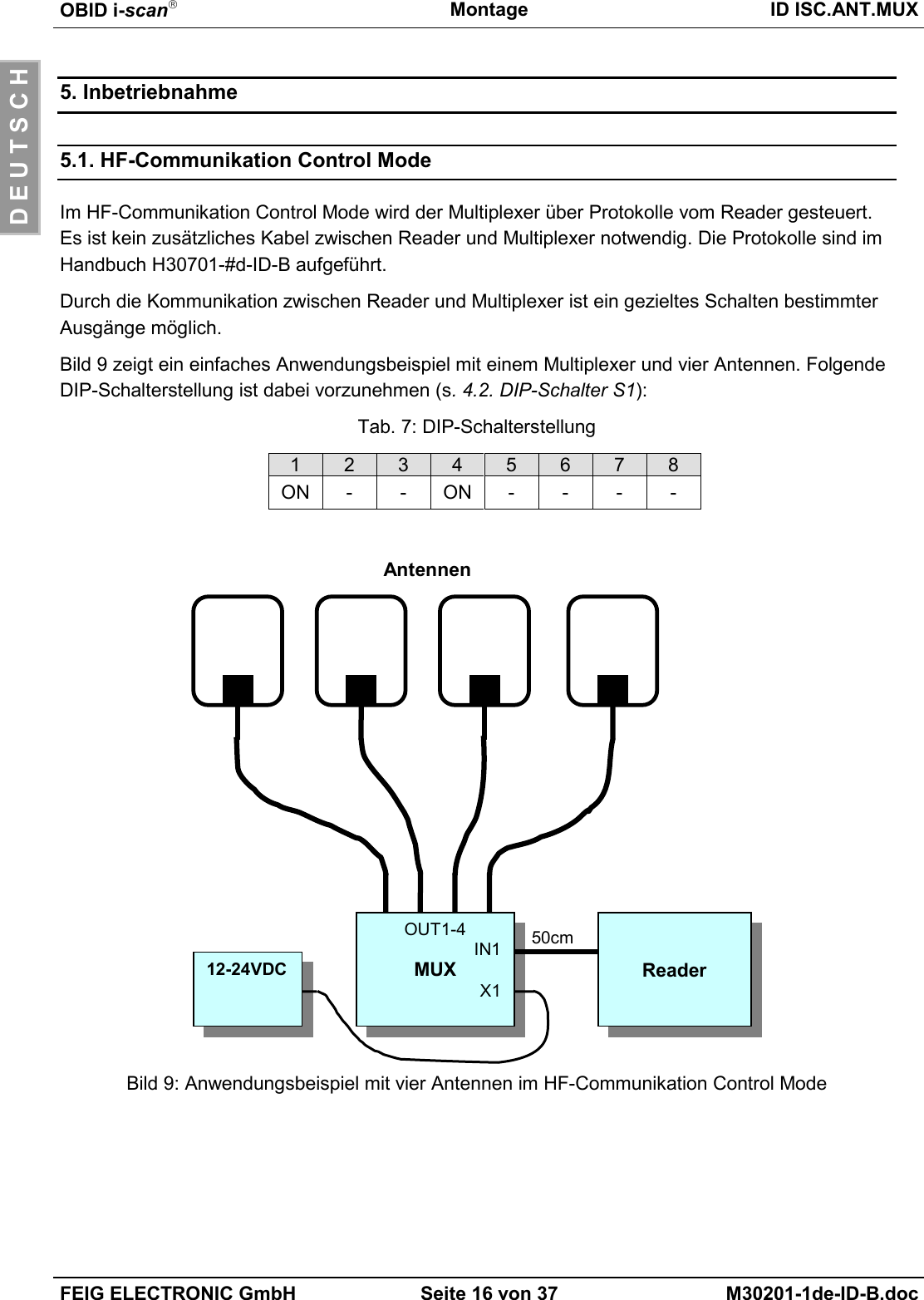
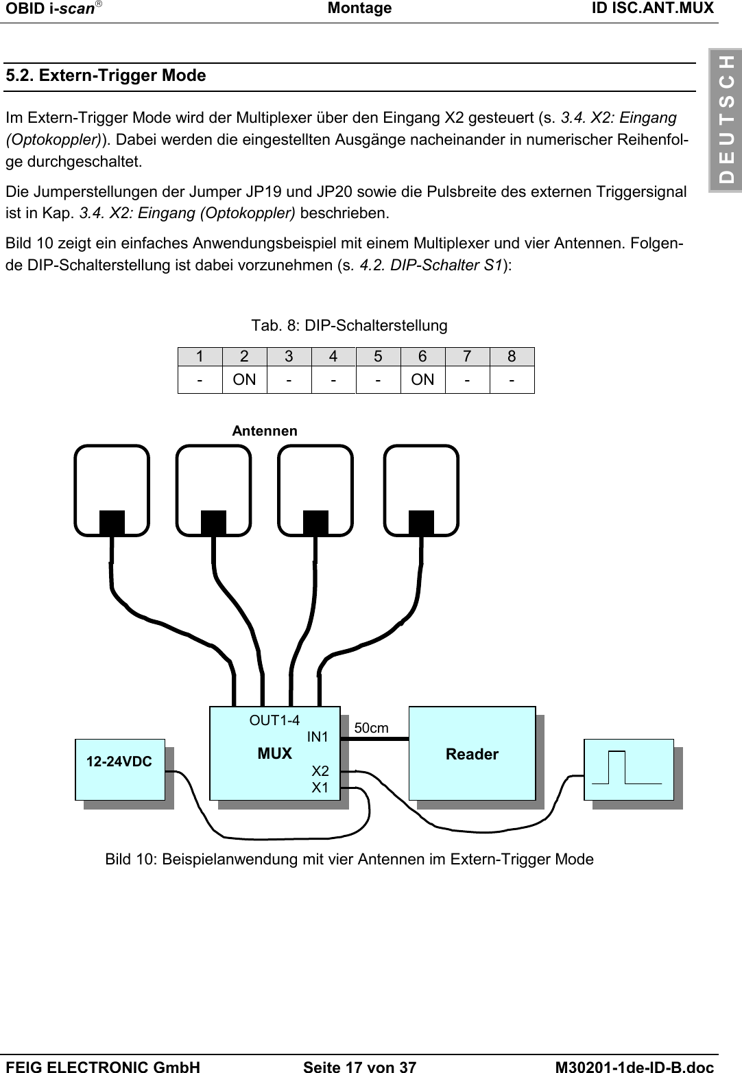
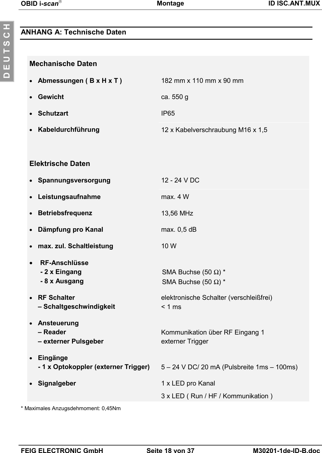
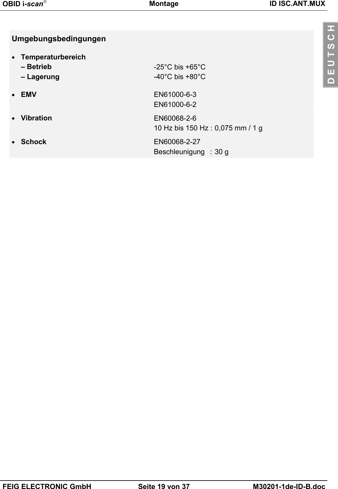
Feig Electronic LRM1002 ID ISC.LRM1002 wth ID ISC.ANT.Mux and ID ISC.ANT800/600-DA User Manual Testreport ETS 300 335
Feig Electronic GmbH ID ISC.LRM1002 wth ID ISC.ANT.Mux and ID ISC.ANT800/600-DA Testreport ETS 300 335
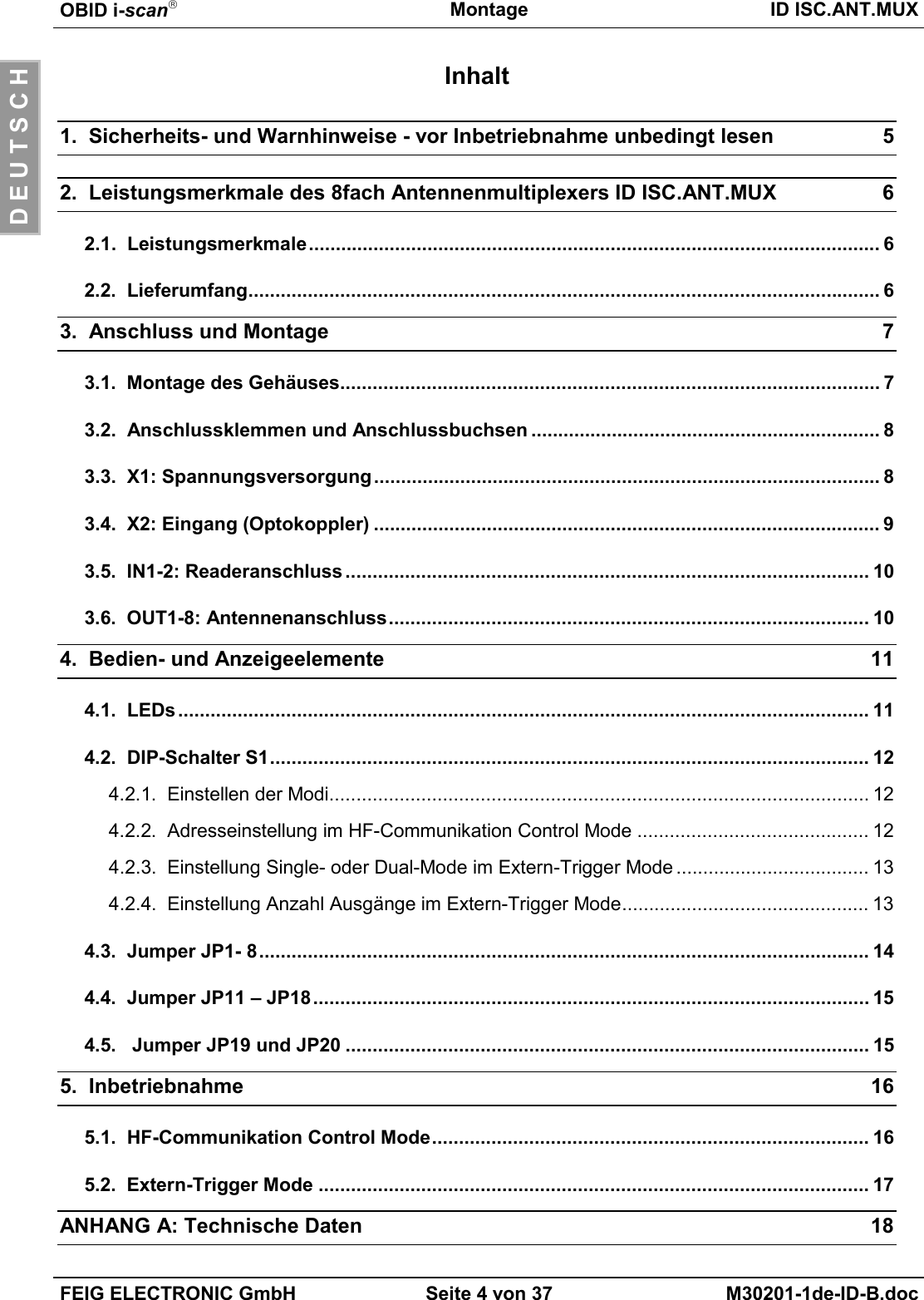
Contents
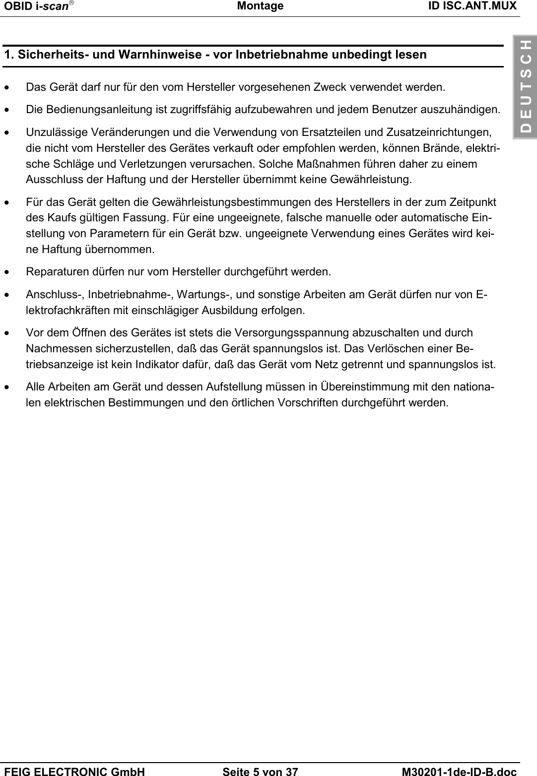
- 1. user manual
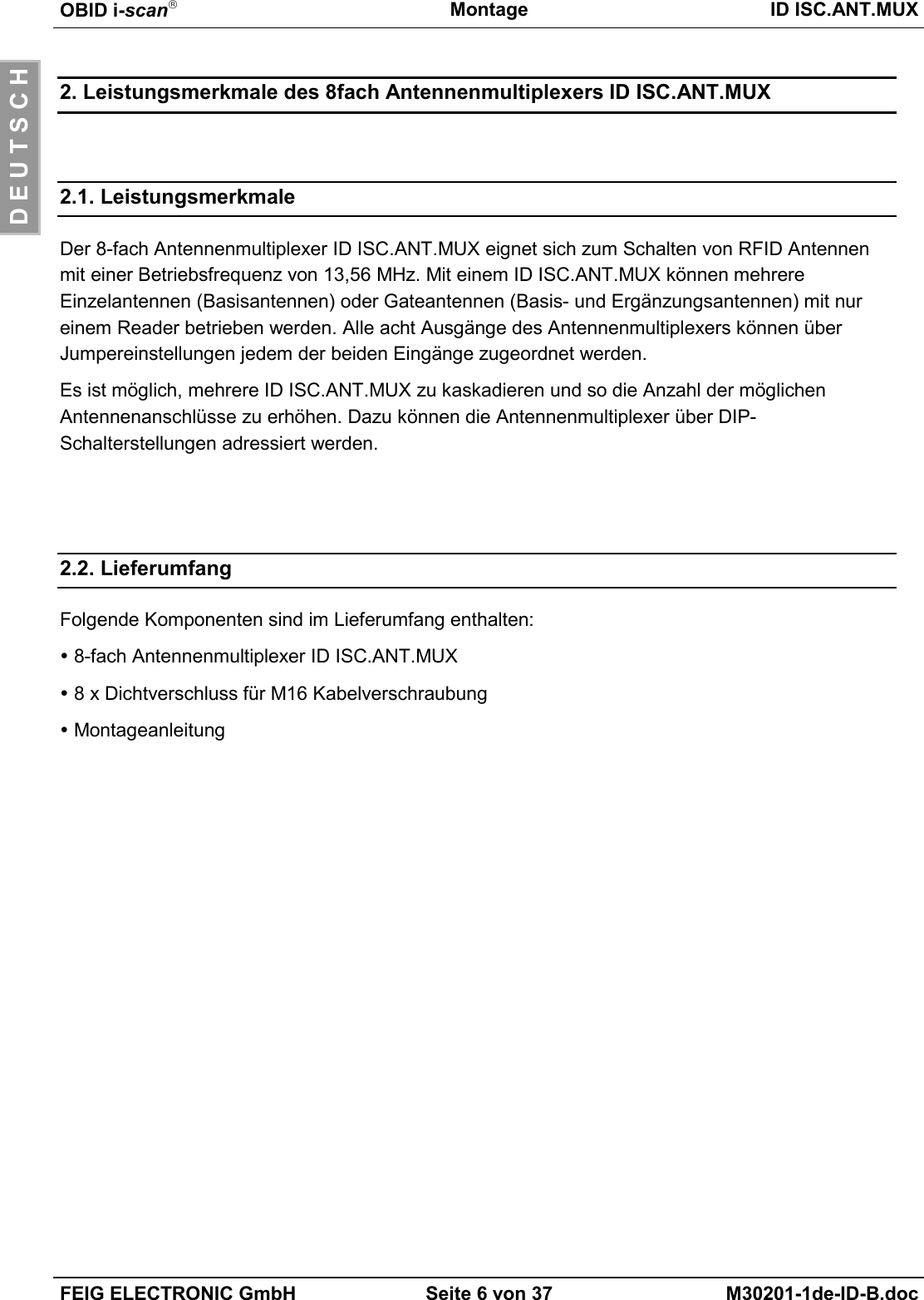
- 2. User manual
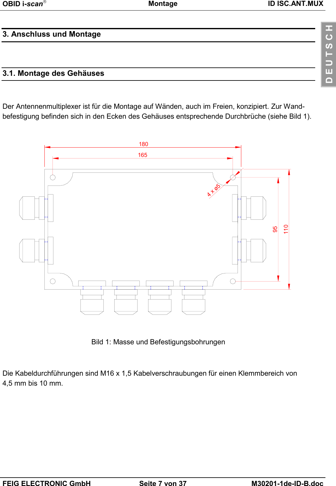
- 3. Users Manual
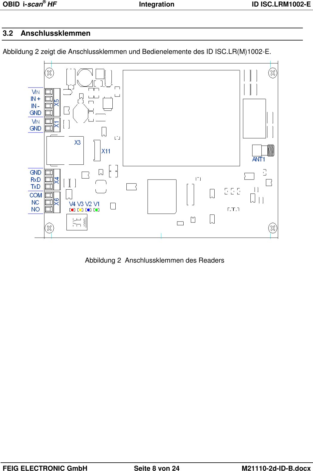
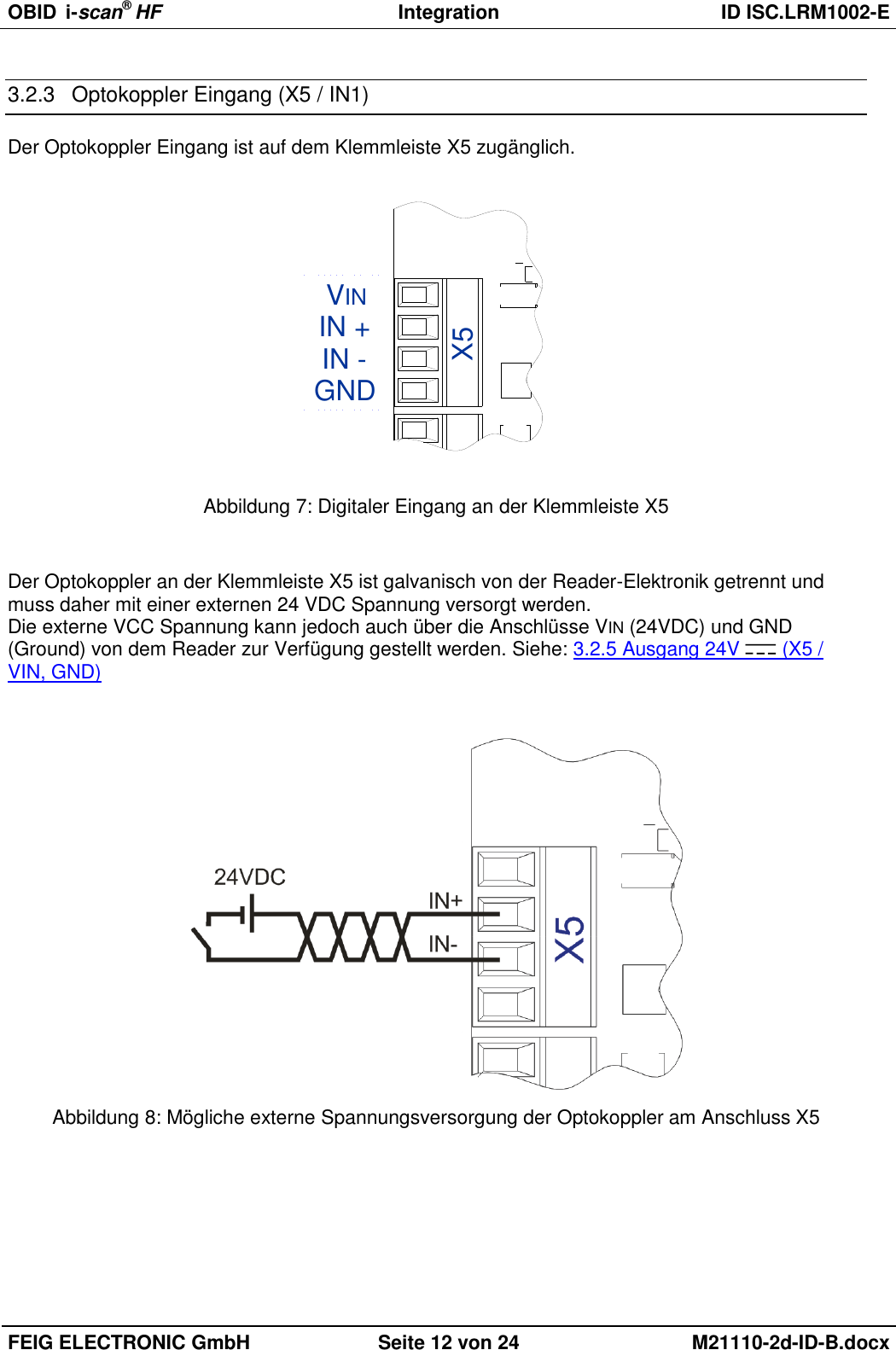
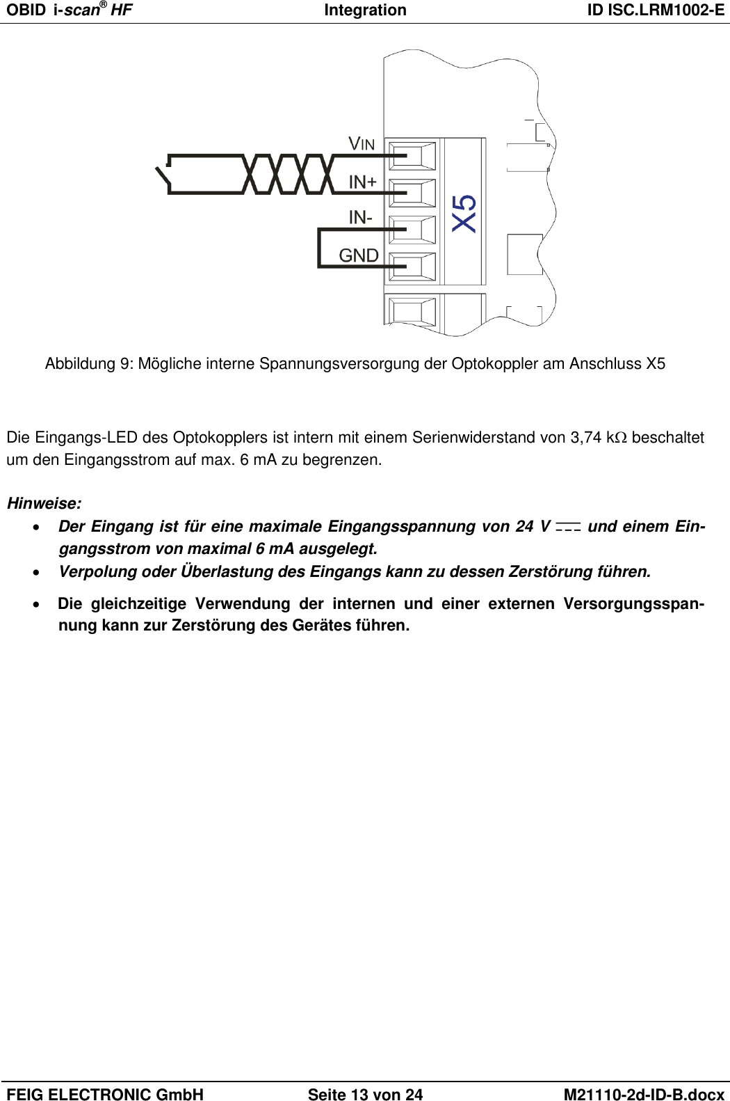
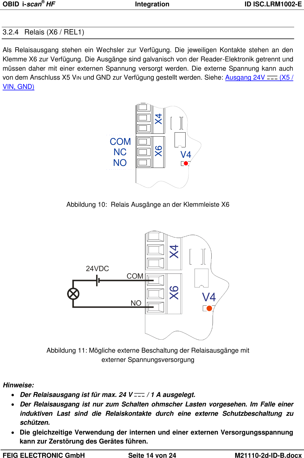
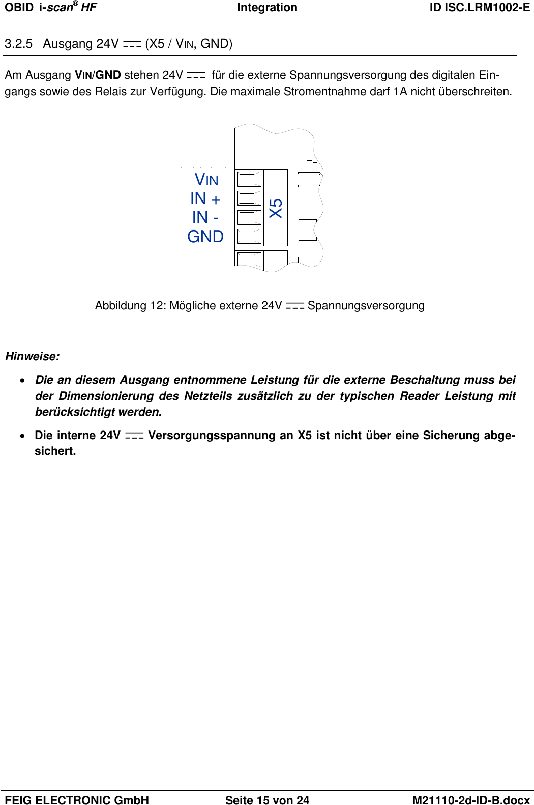
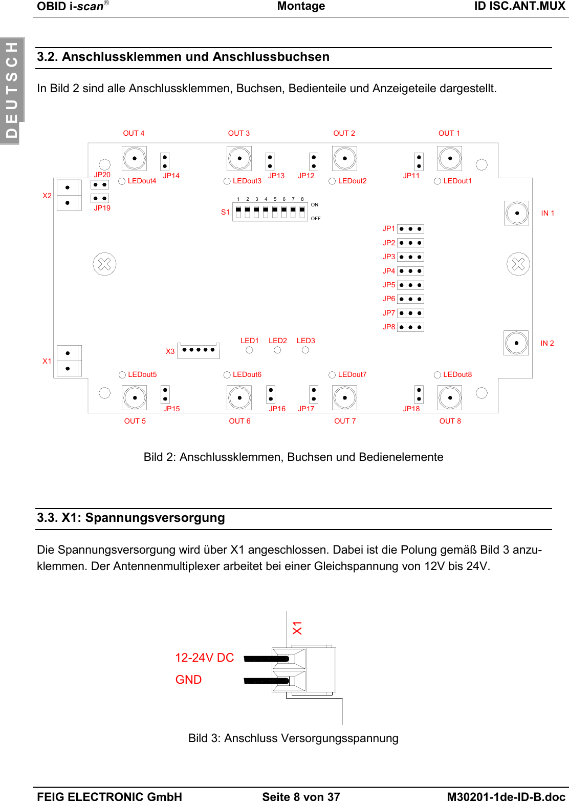
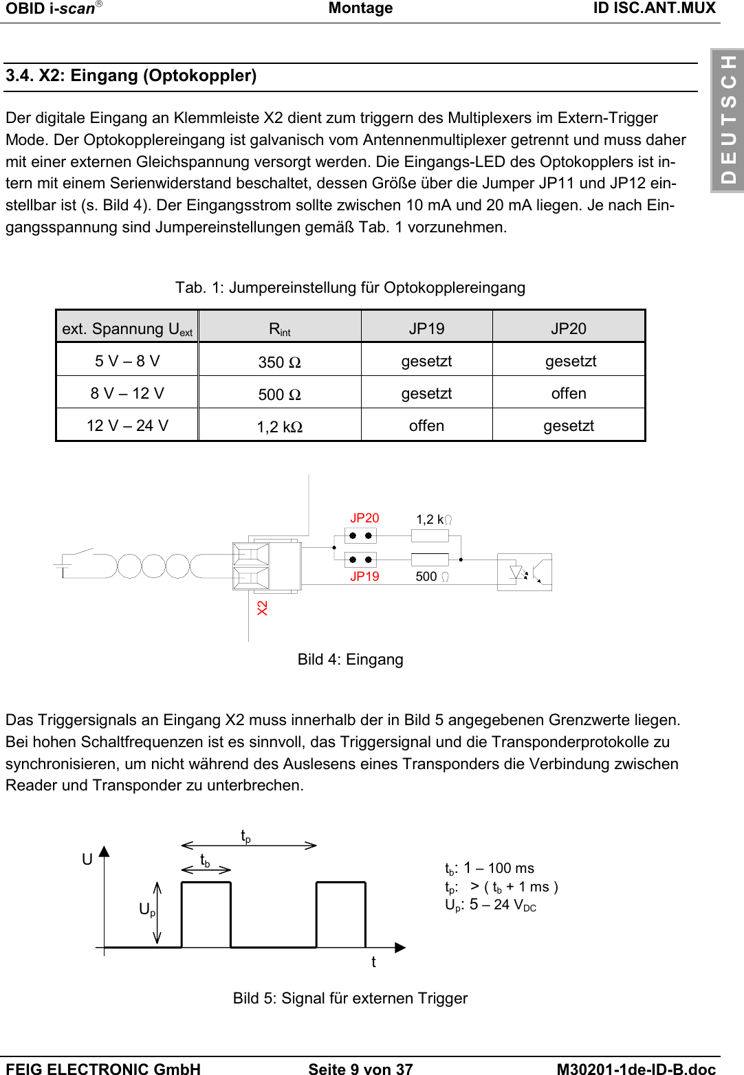
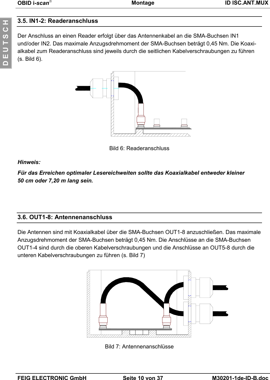
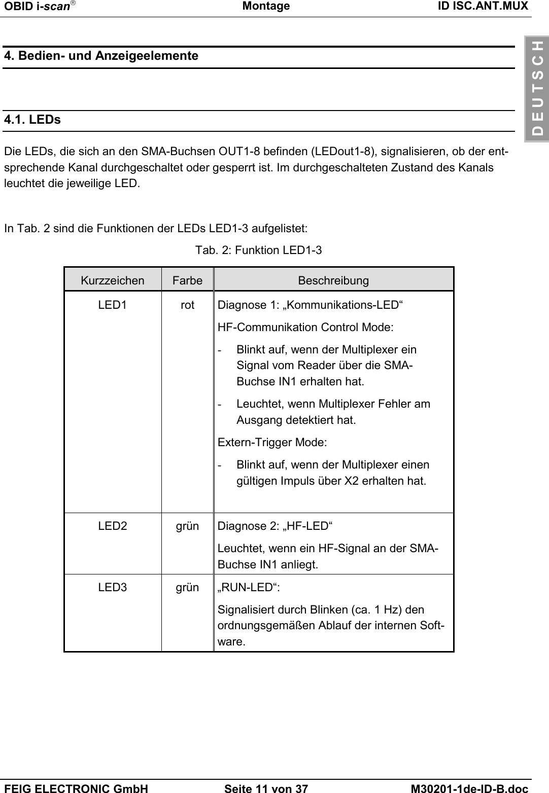
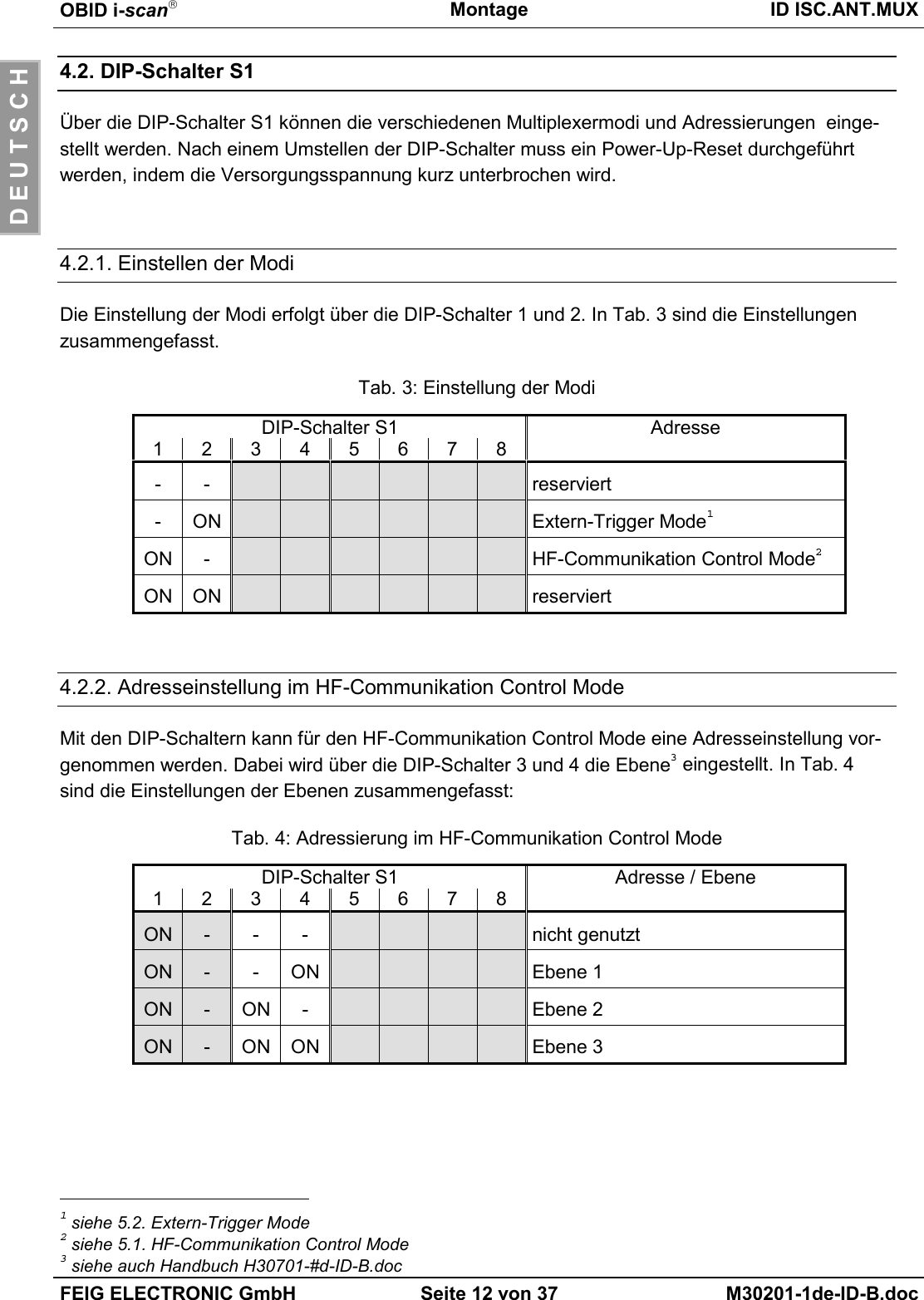
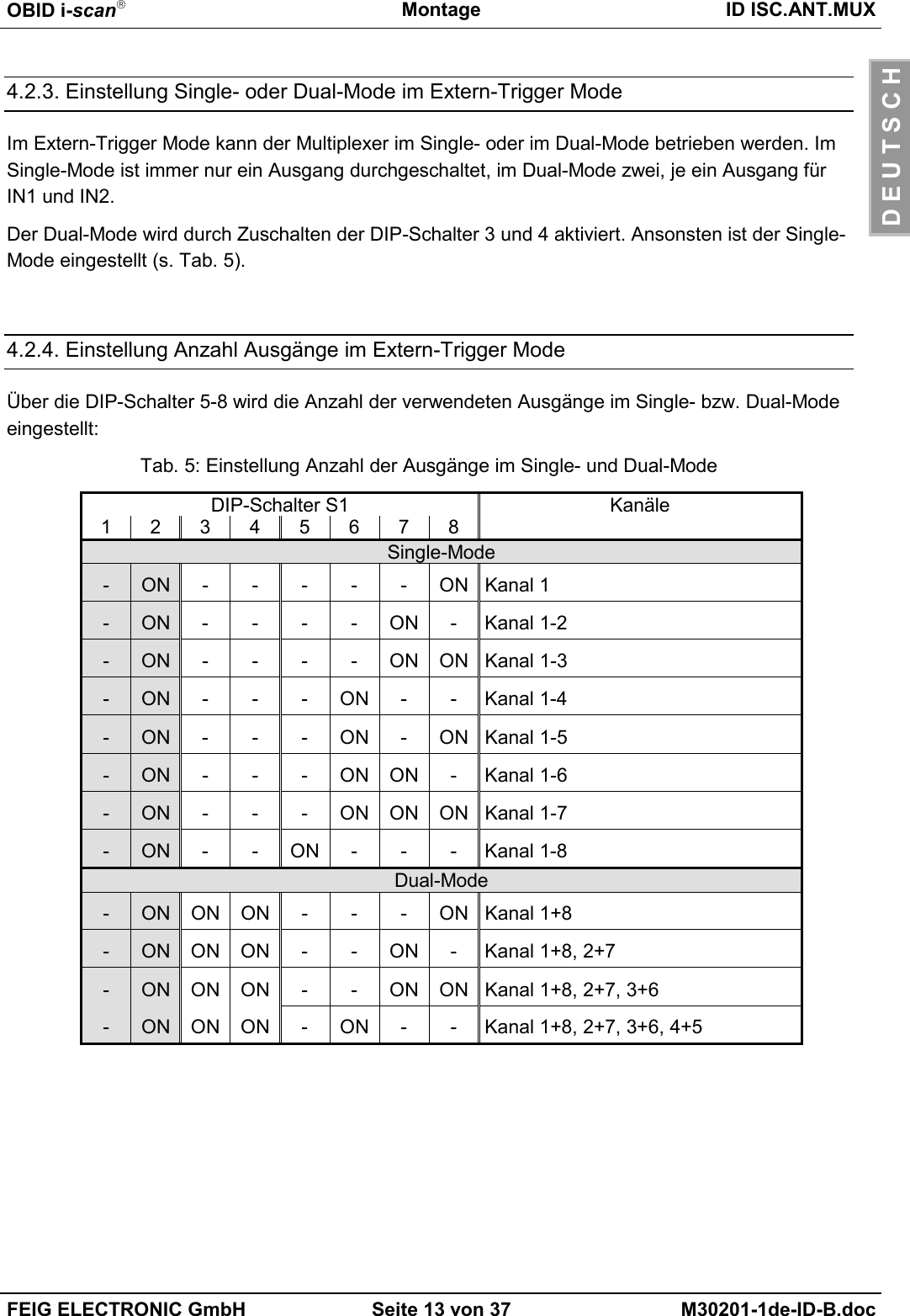
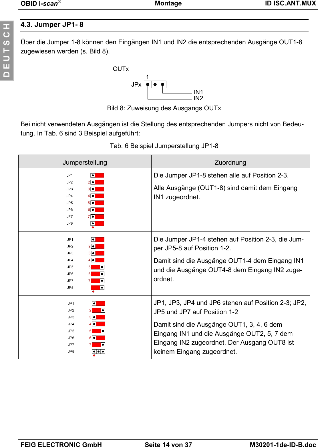
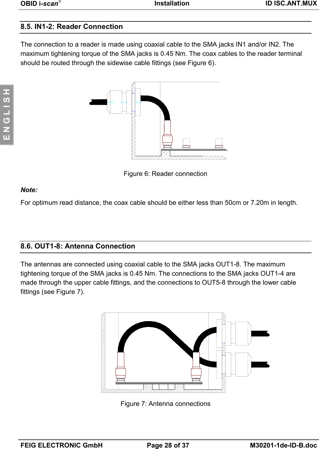
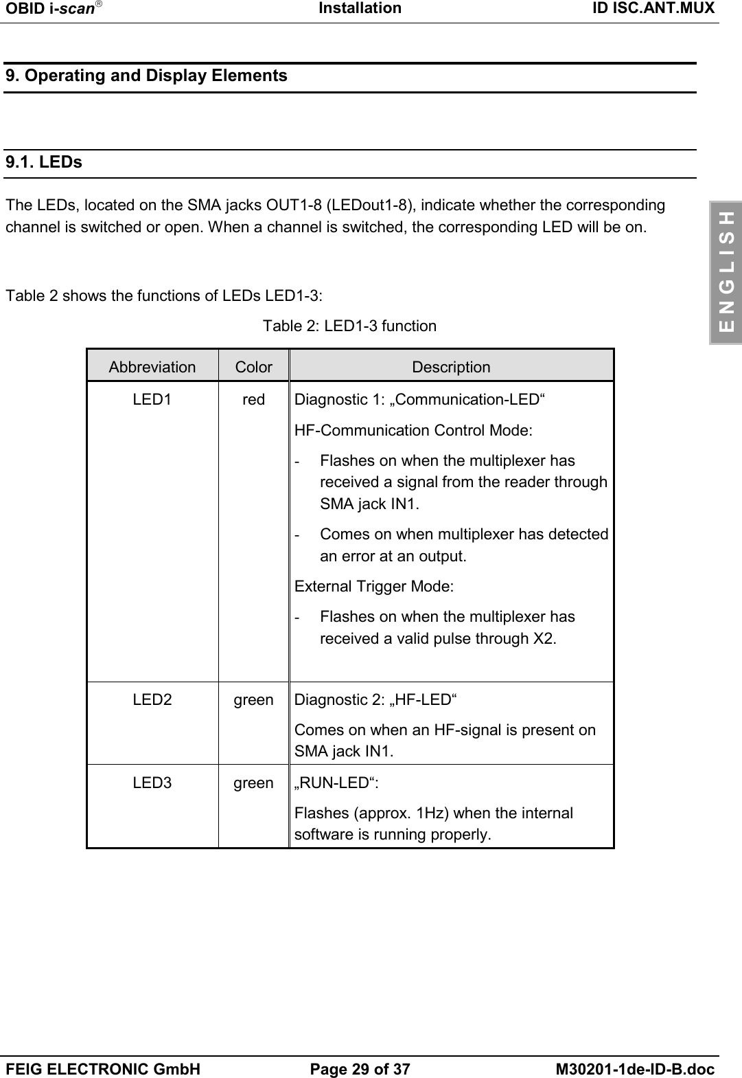
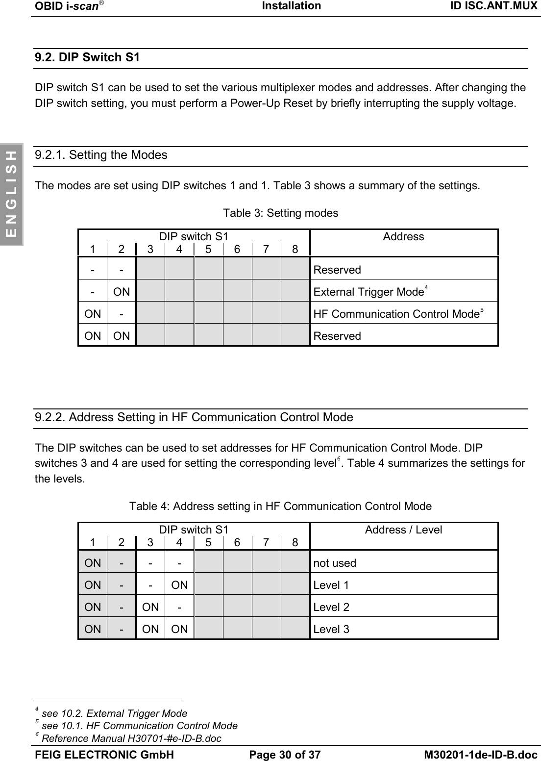
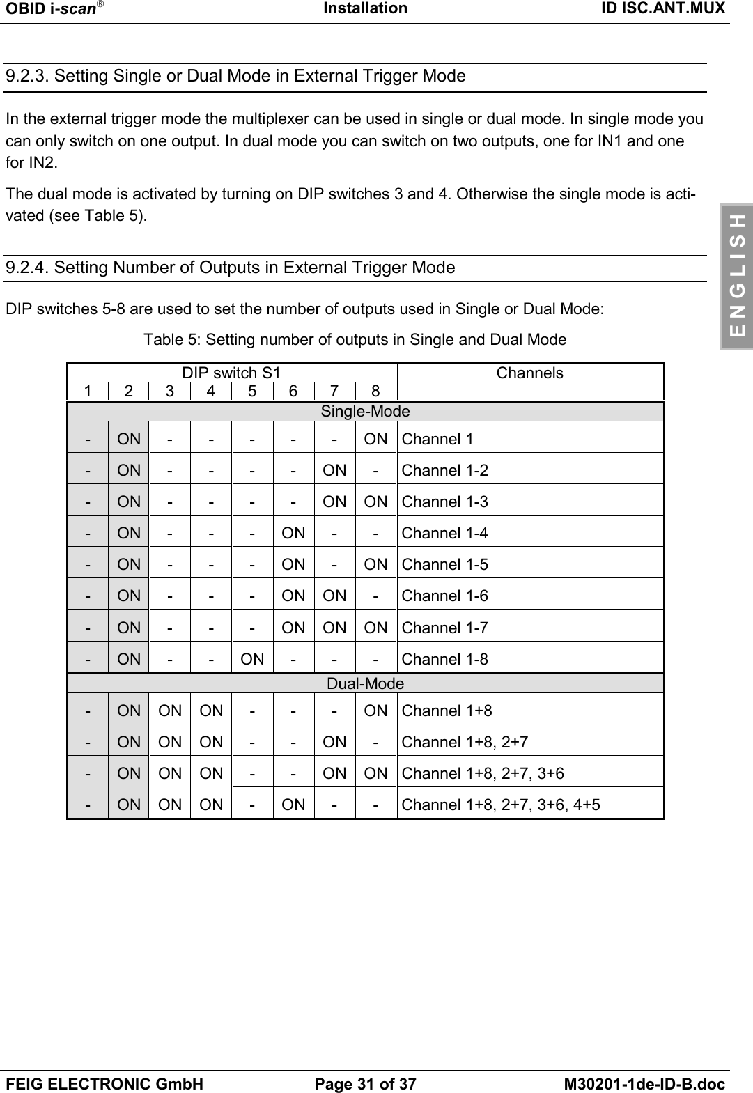
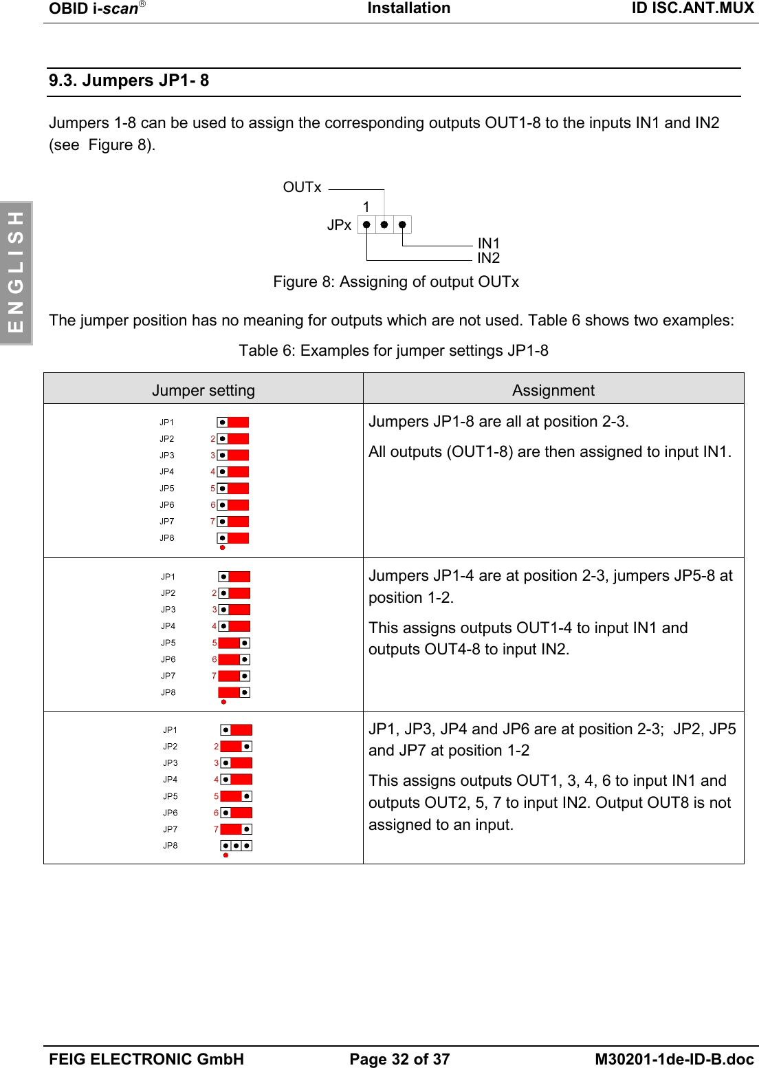
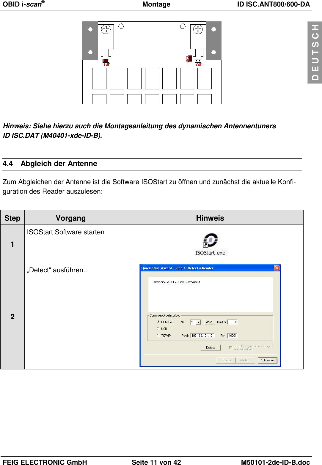
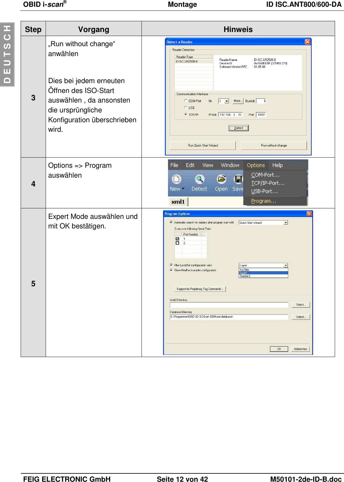
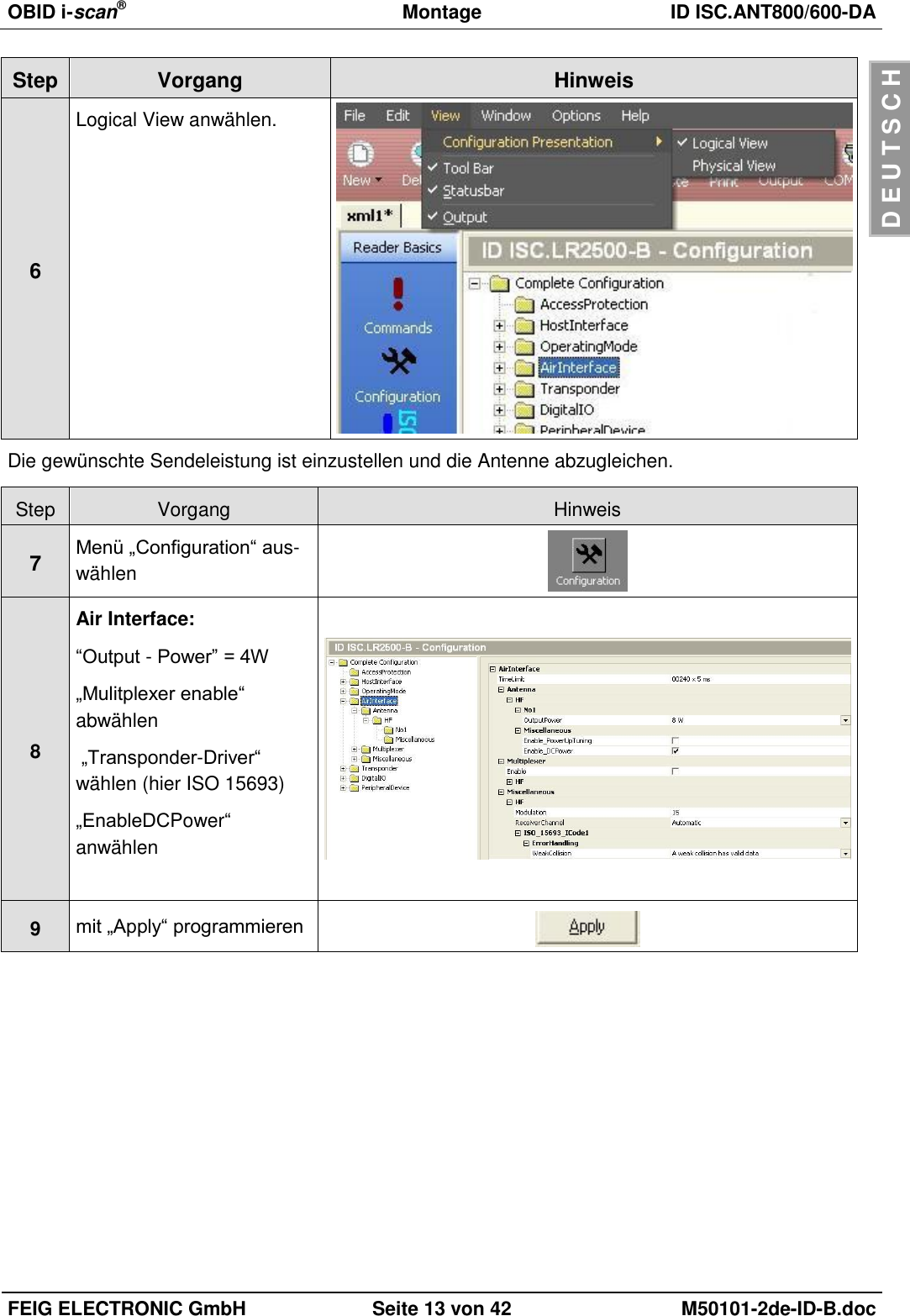
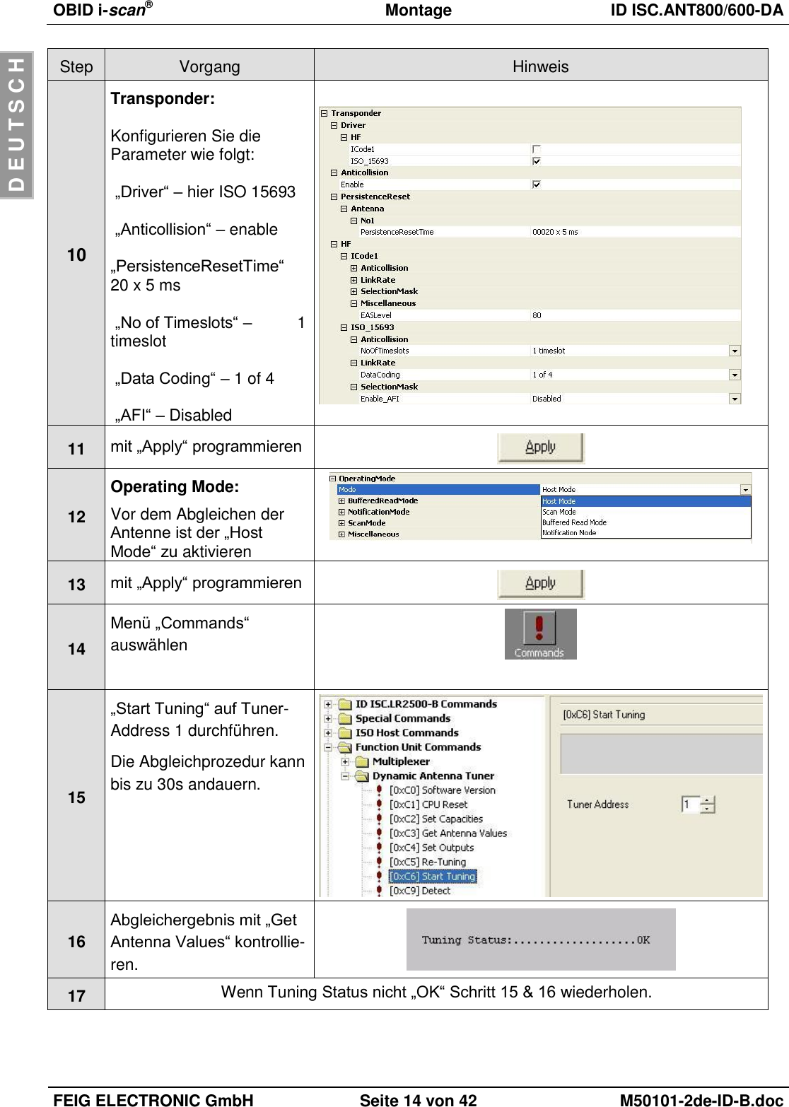
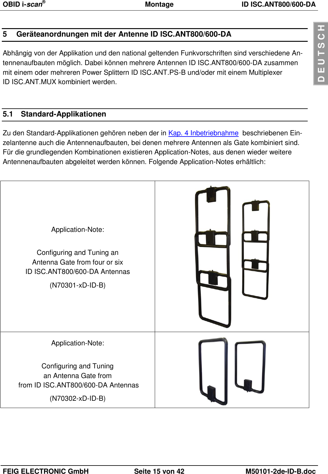
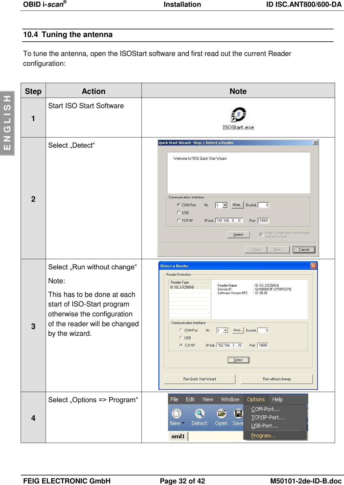
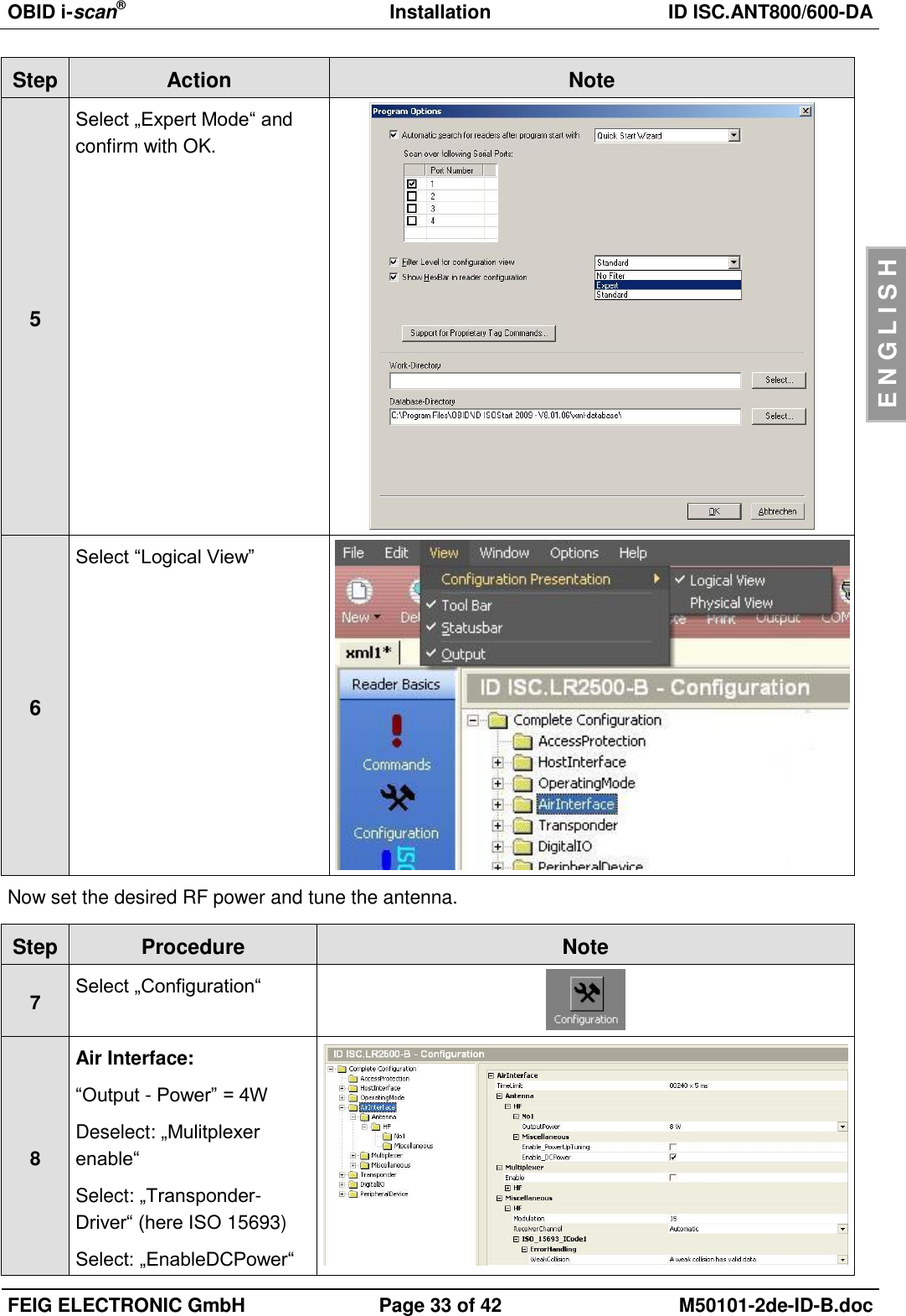
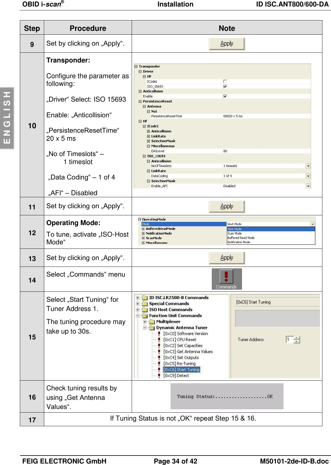
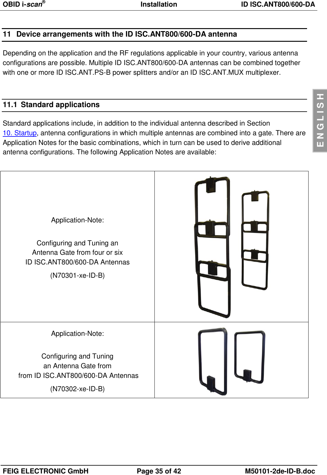
User manual