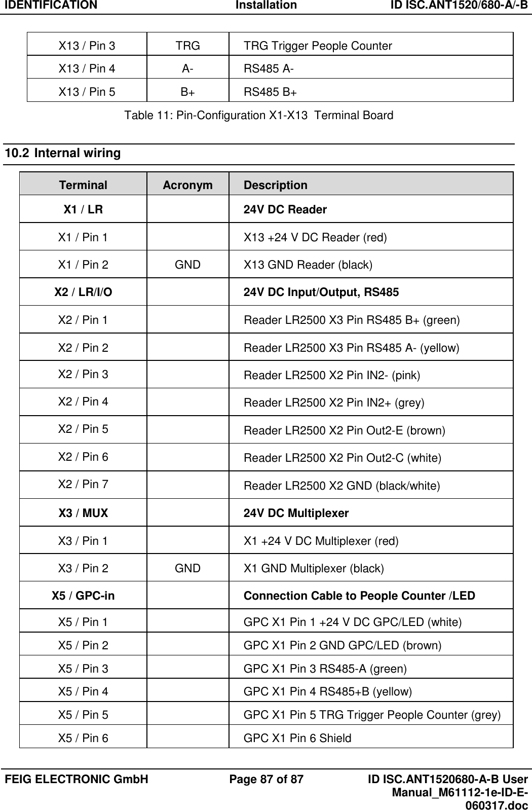
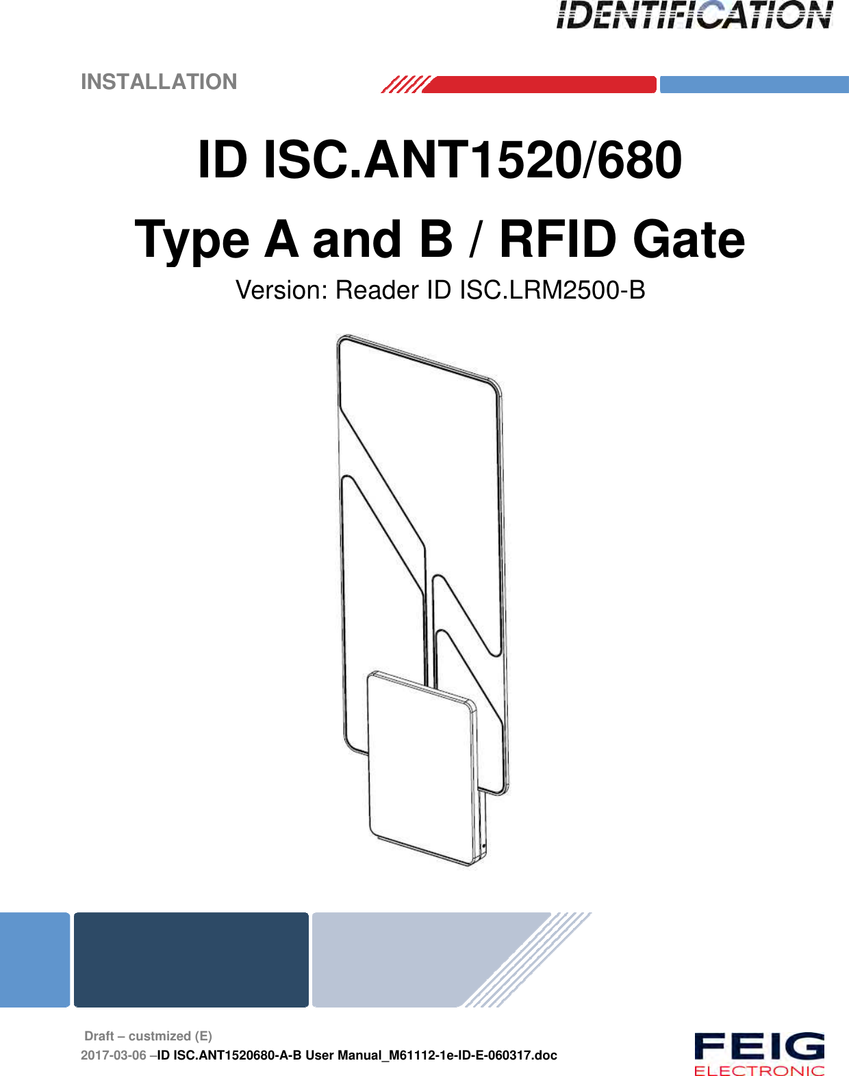
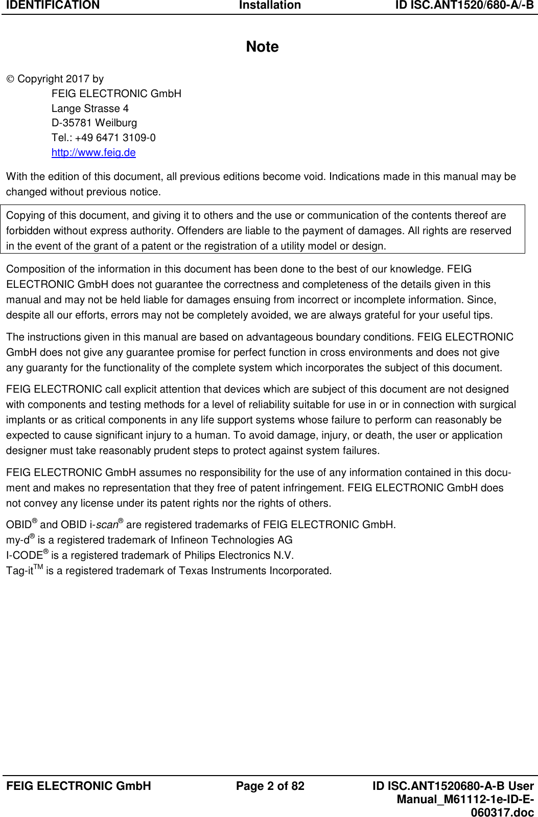
Feig Electronic LRM2500 ID ISC.ANT1520/680 (RFID gate) User Manual Testreport ETS 300 335
Feig Electronic GmbH ID ISC.ANT1520/680 (RFID gate) Testreport ETS 300 335
UserManual.wiki
>
Feig Electronic
>
LRM2500 User Manual
>
Users Manual
Contents
1.
User Manual
2.
User Manual II
3.
Users Manual
Users Manual
Navigation menu
Upload a User Manual
Namespaces
Wiki Guide
HTML
PDF
Info
Views
User Manual
Discussion / Help
Navigation
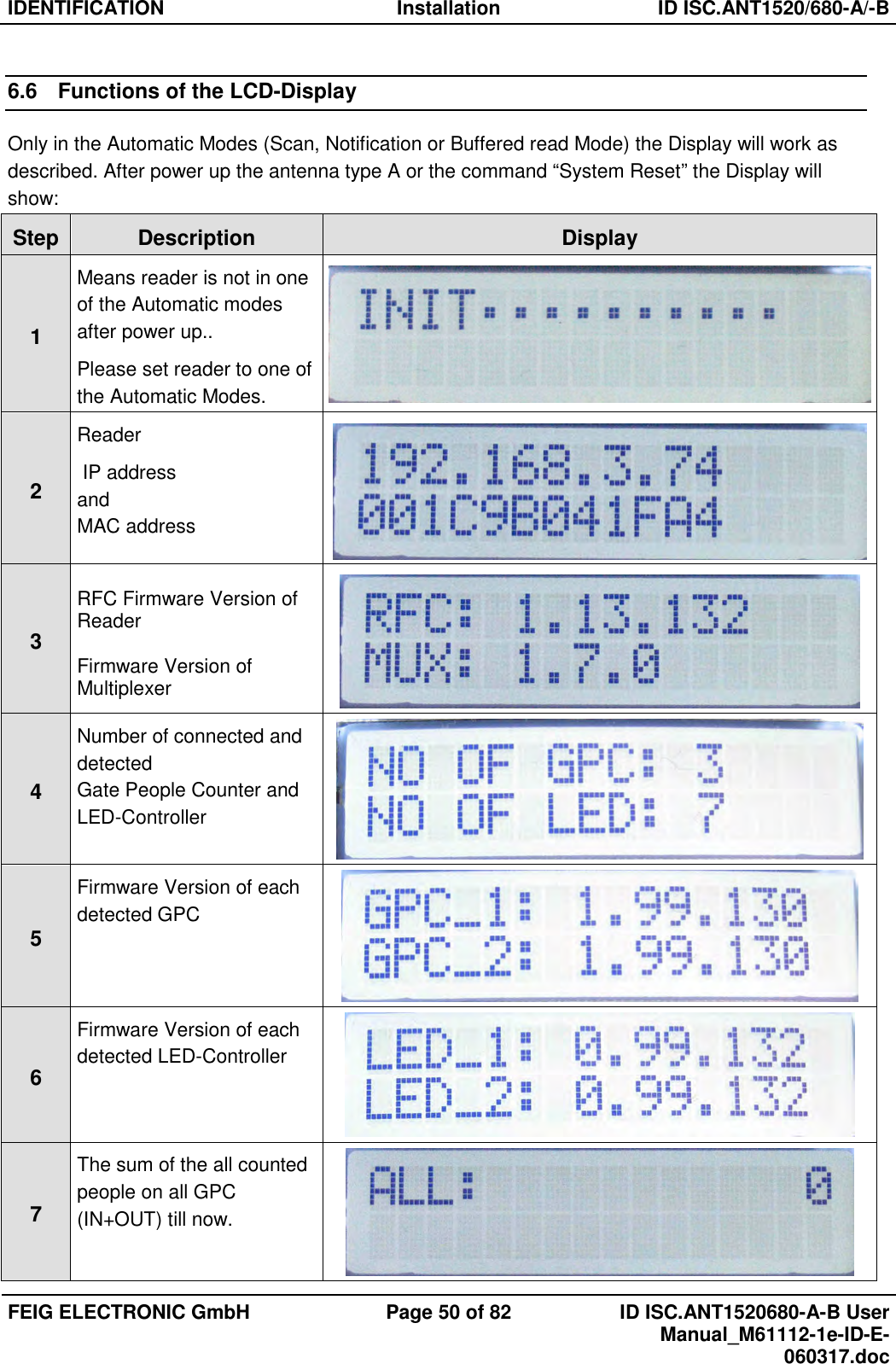
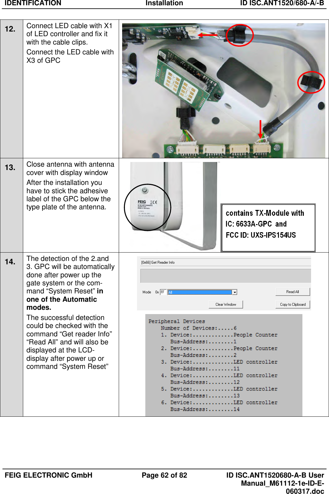
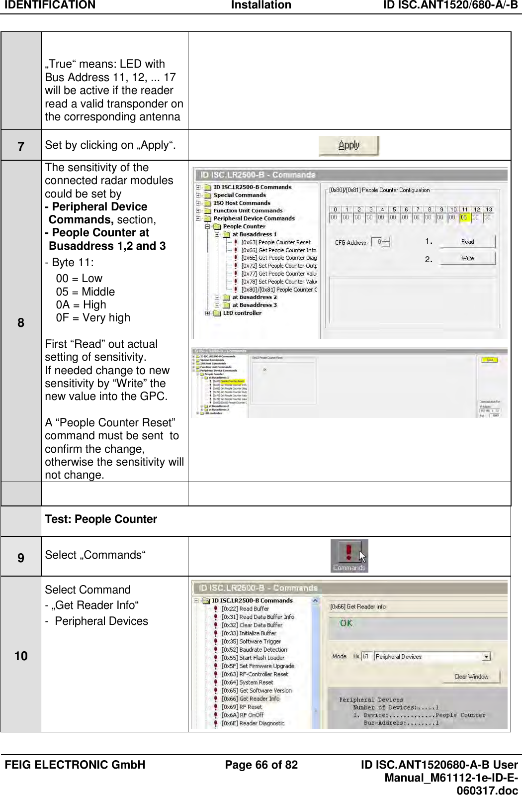
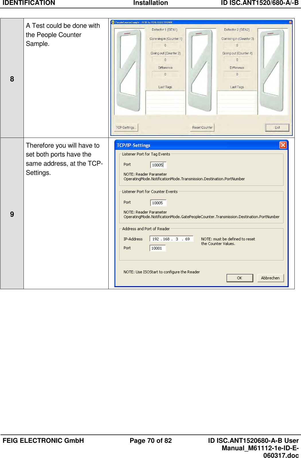
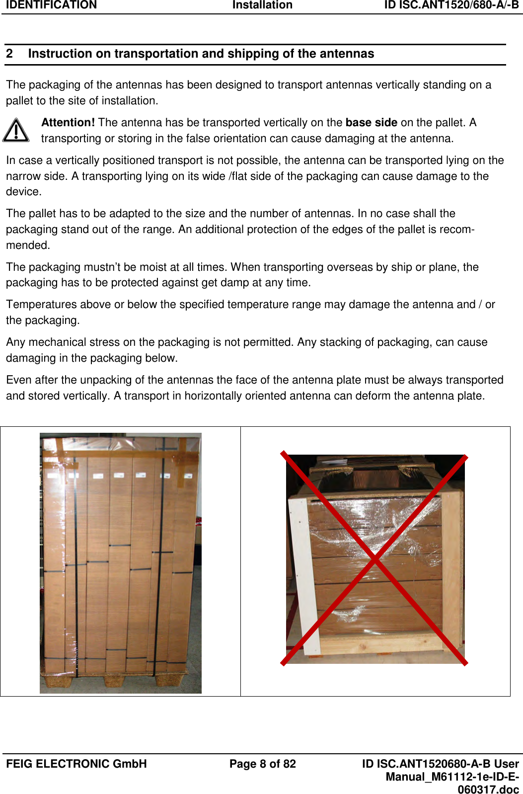
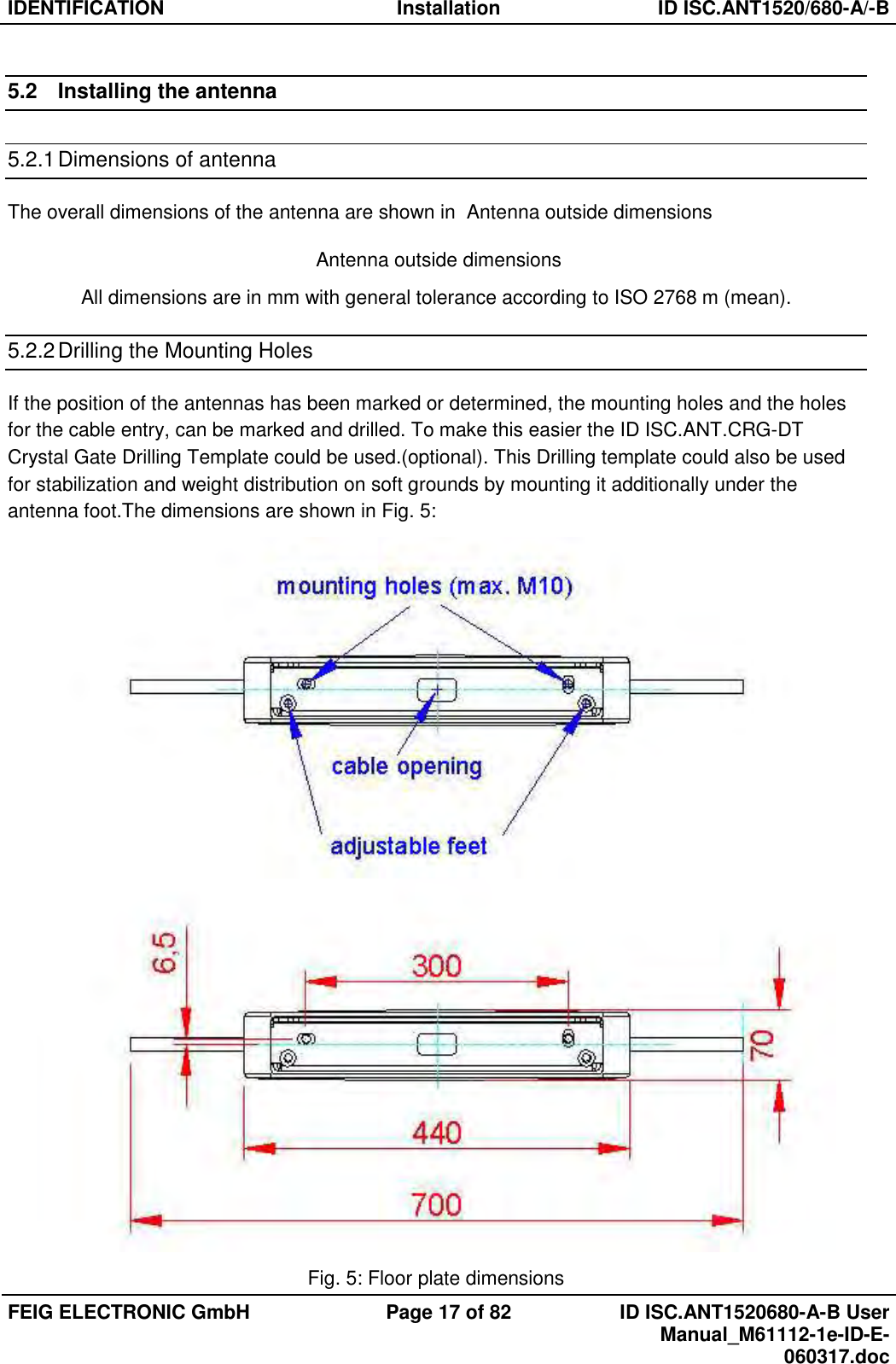
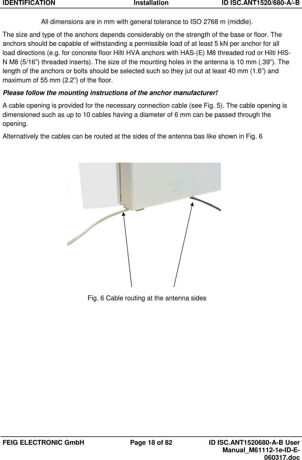
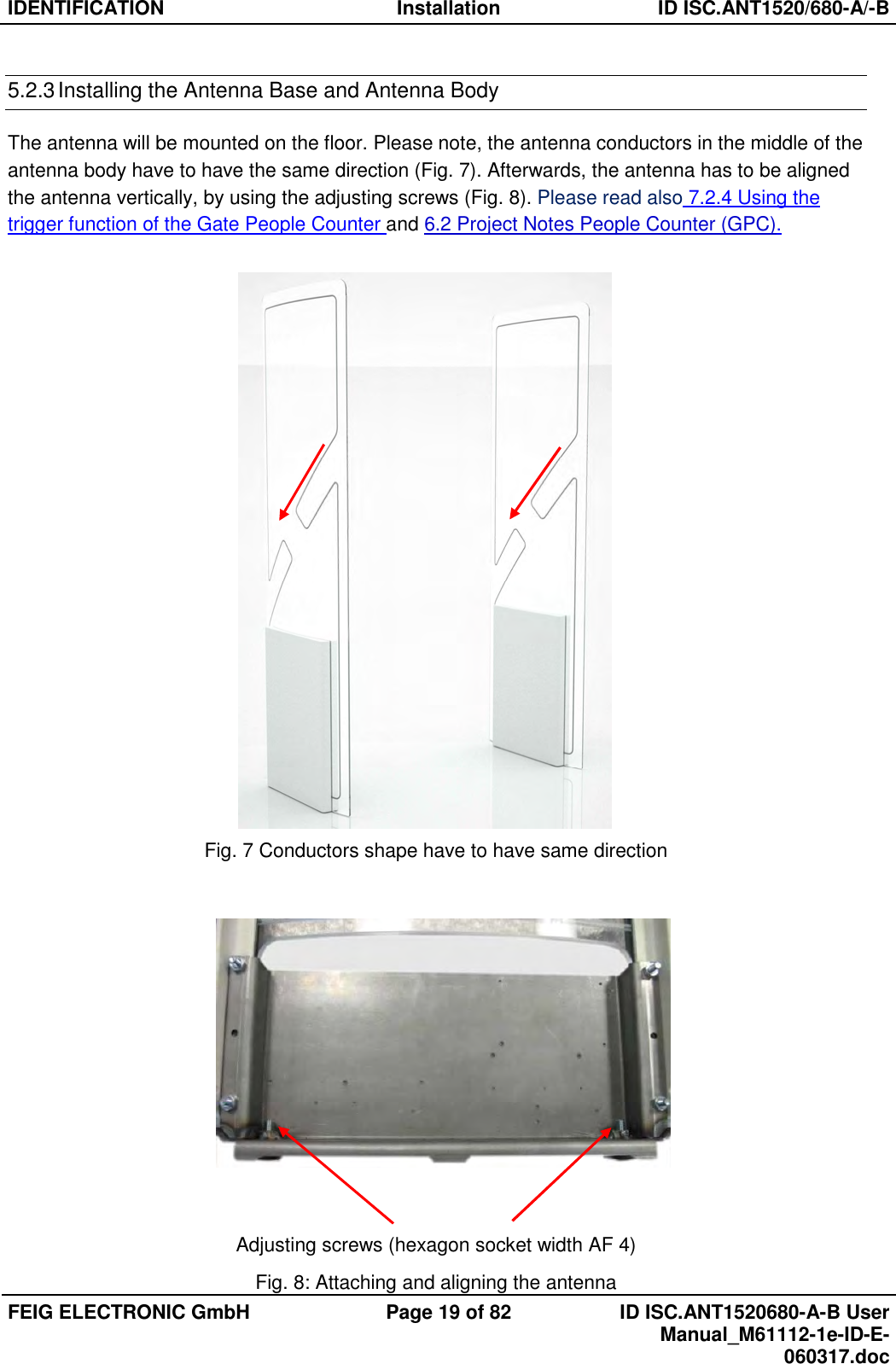
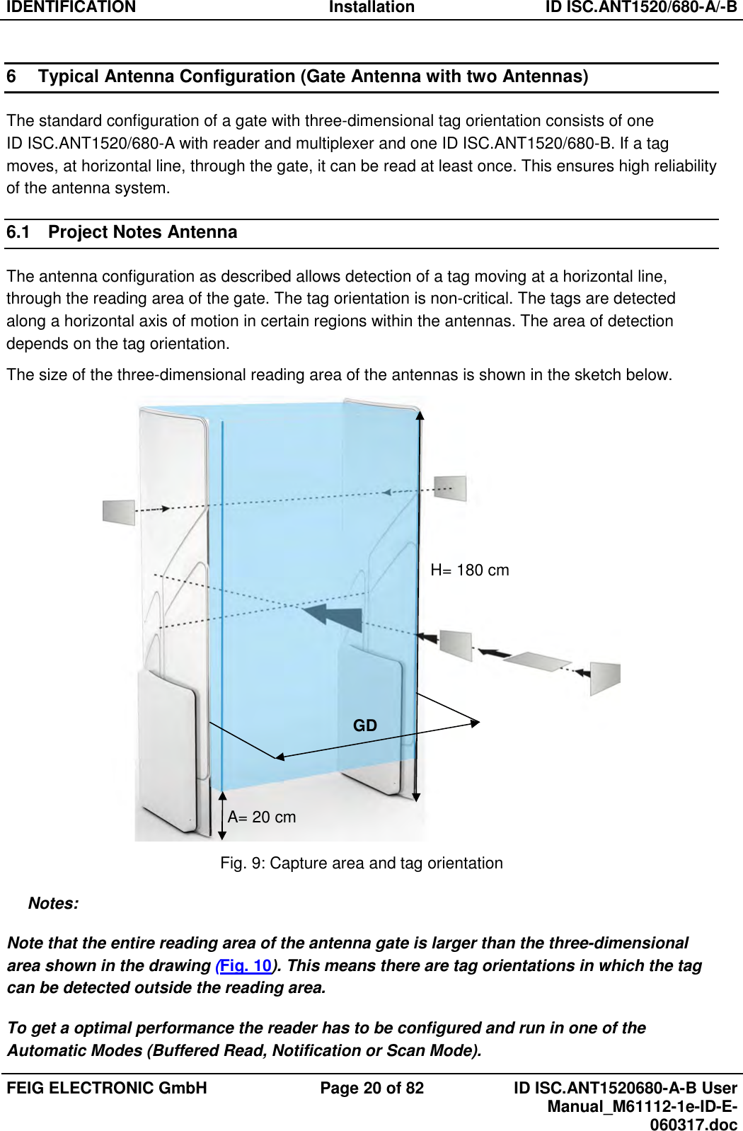
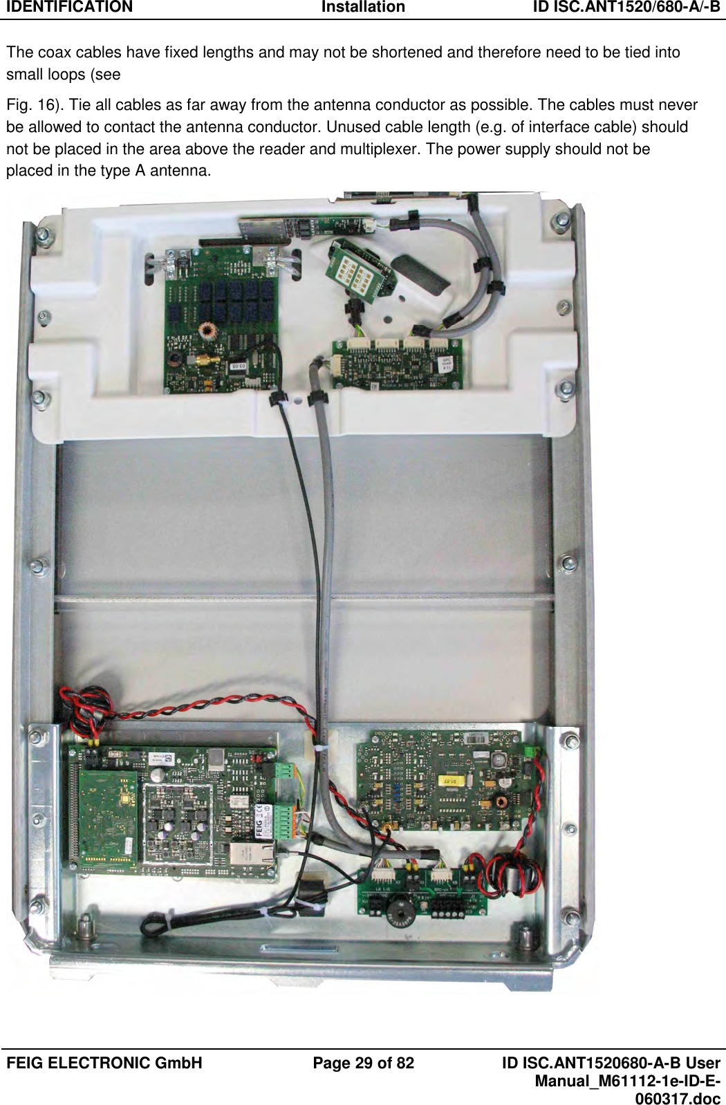
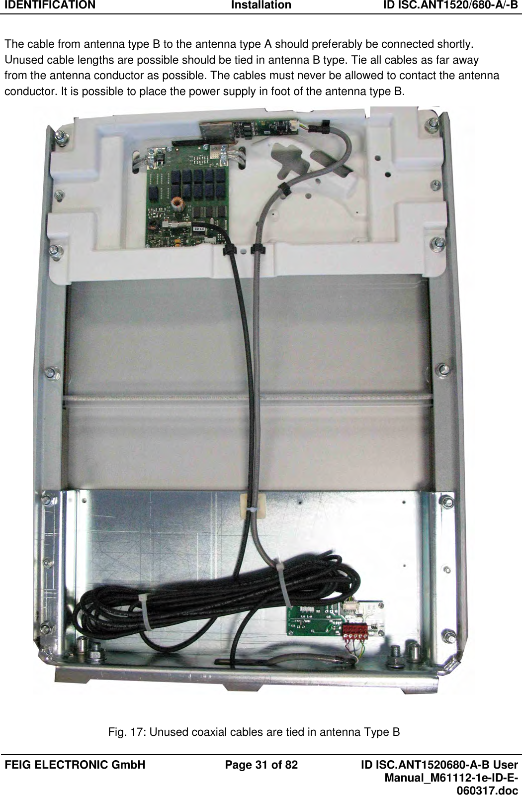
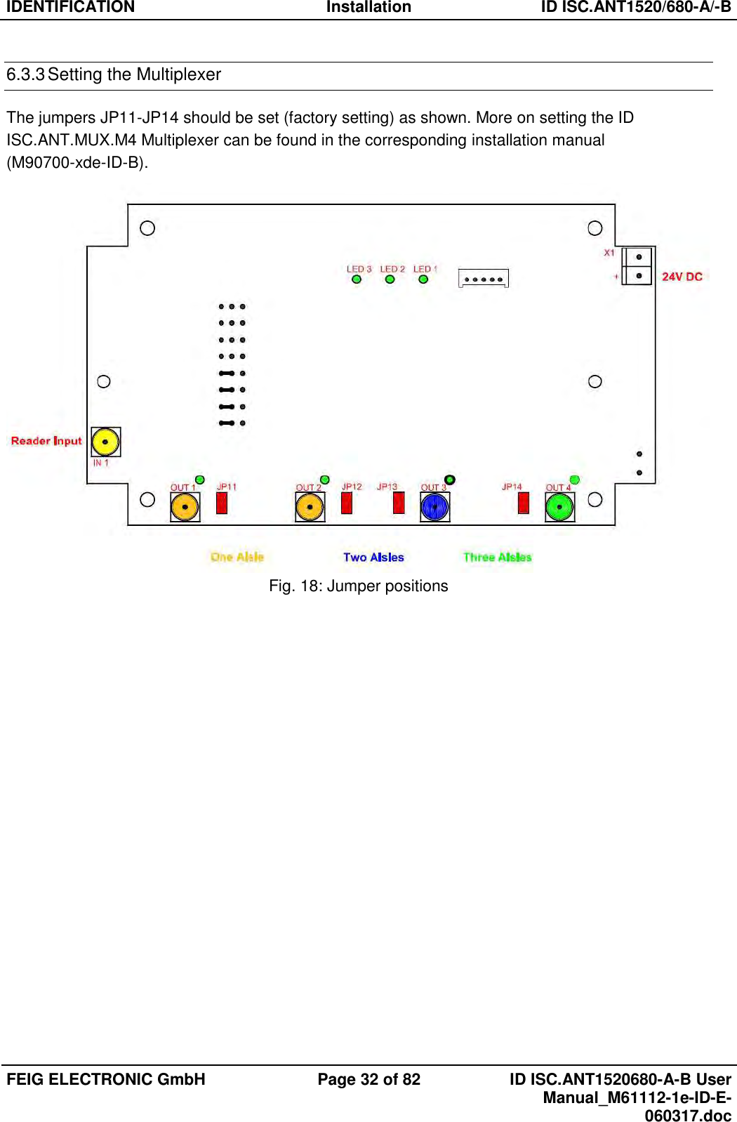
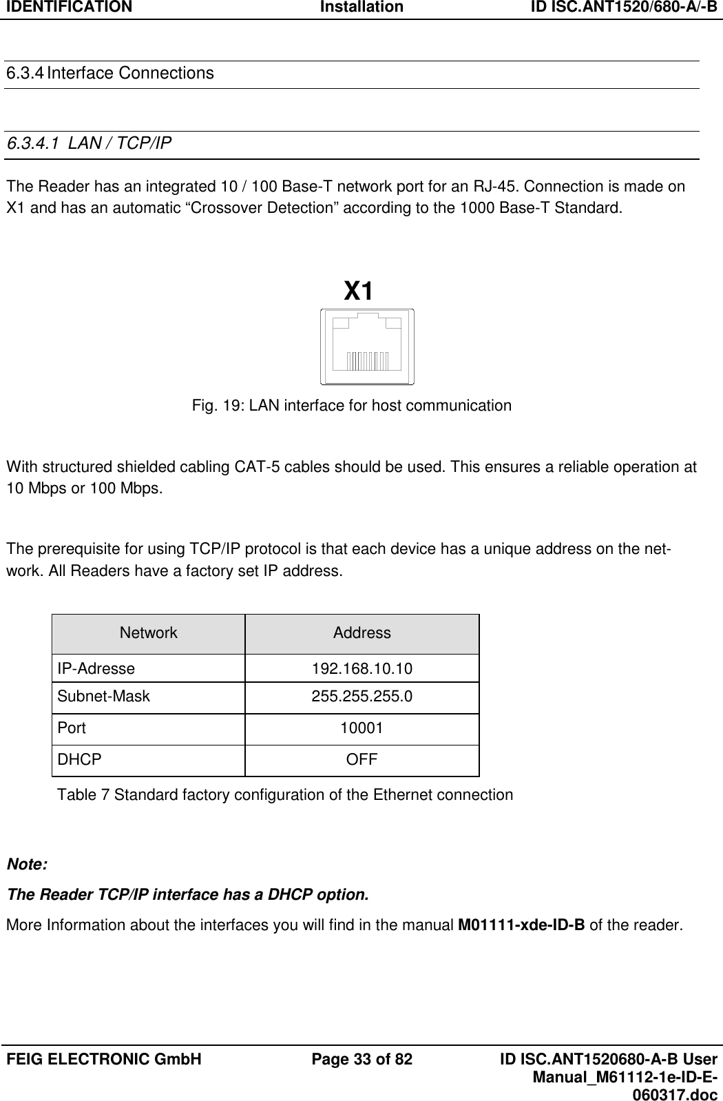
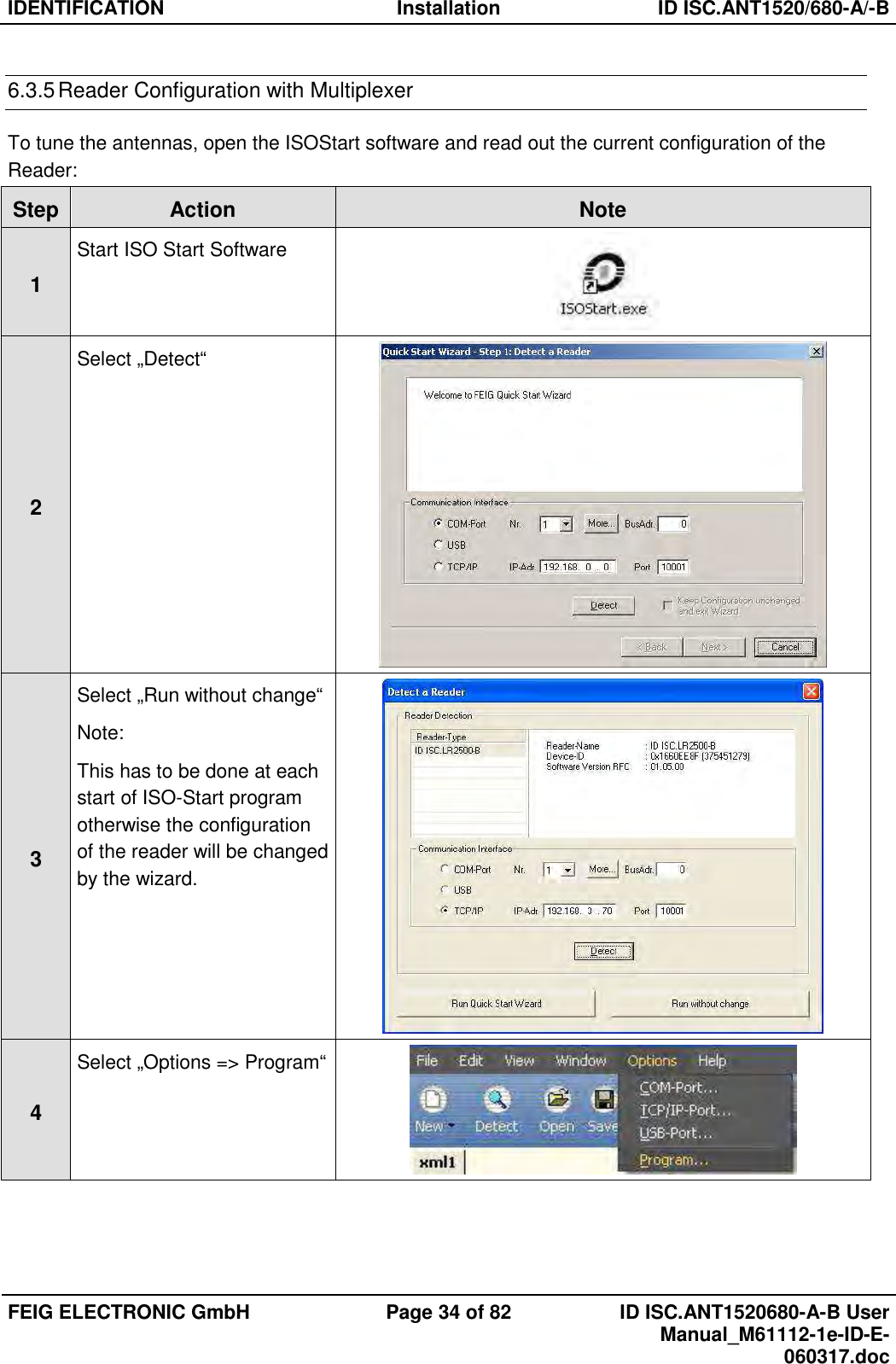
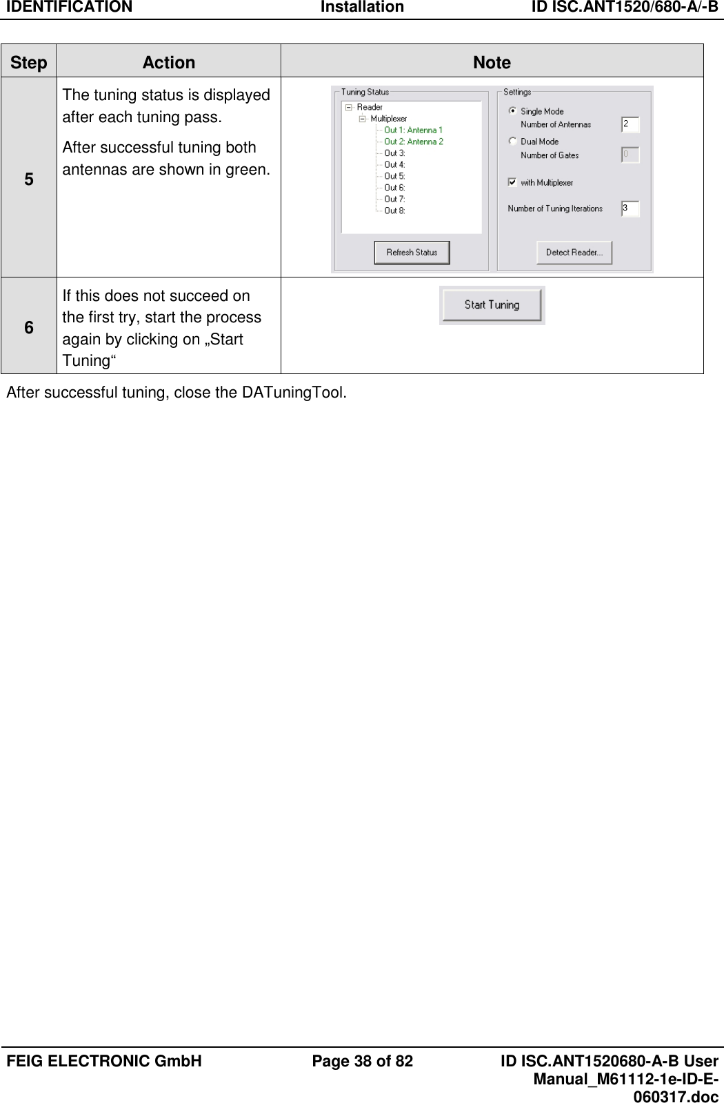
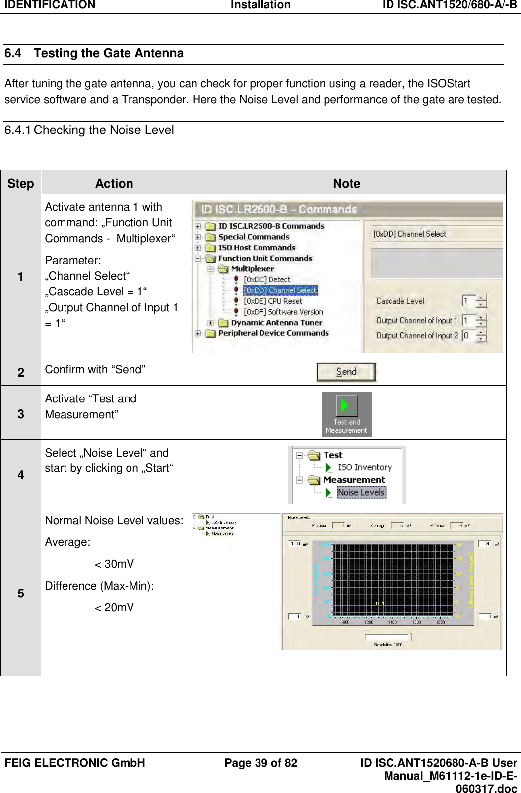
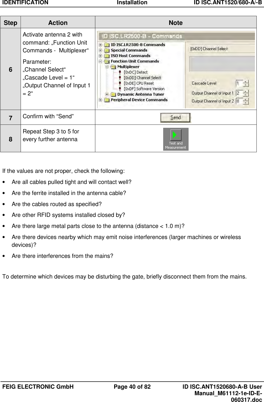
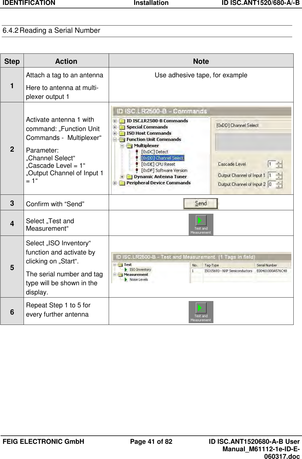
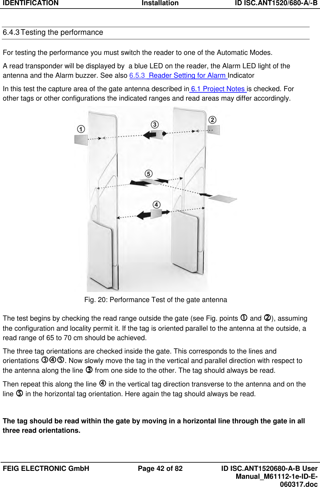
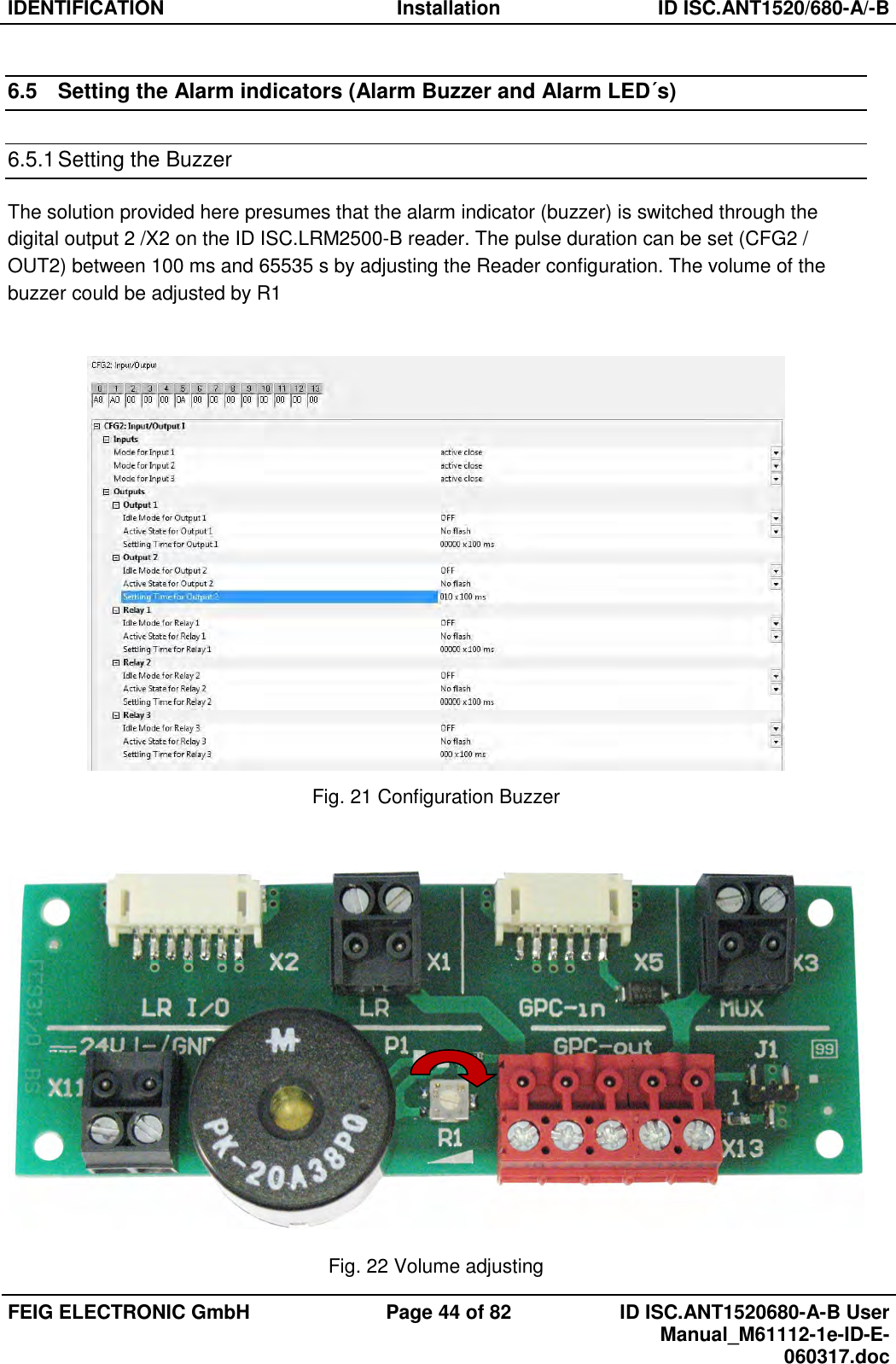
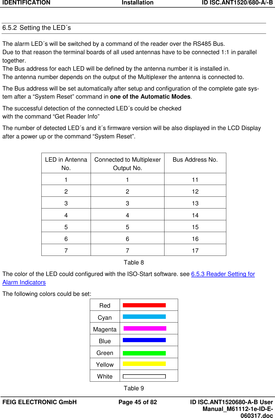
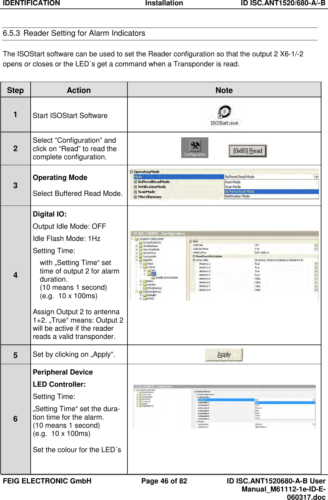
![IDENTIFICATION Installation ID ISC.ANT1520/680-A/-B FEIG ELECTRONIC GmbH Page 3 of 82 ID ISC.ANT1520680-A-B User Manual_M61112-1e-ID-E-060317.doc General information's regarding this document • The sign "" indicates extensions or changes of this manual compared with the former issue. • If bits within one byte are filled with "-", these bit spaces are reserved for future extensions or for internal testing- and manufacturing-functions. These bit spaces must not be changed, as this may cause faulty operation of the reader. • The following figure formats are used: 0...9: for decimal figures 0x00...0xFF: for hexadecimal figures, b0...1 for binary figures. • The hexadecimal value in brackets "[ ]" marks a control byte (command).](https://usermanual.wiki/Feig-Electronic/LRM2500.Users-Manual/User-Guide-3314321-Page-4.png)

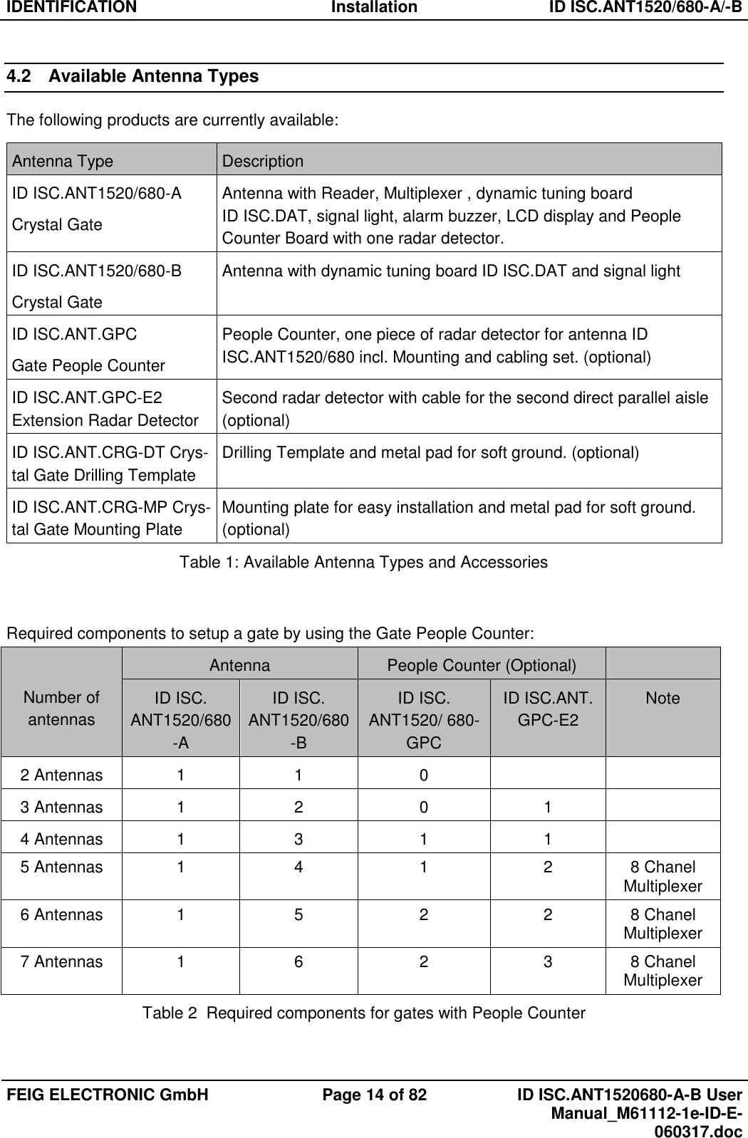

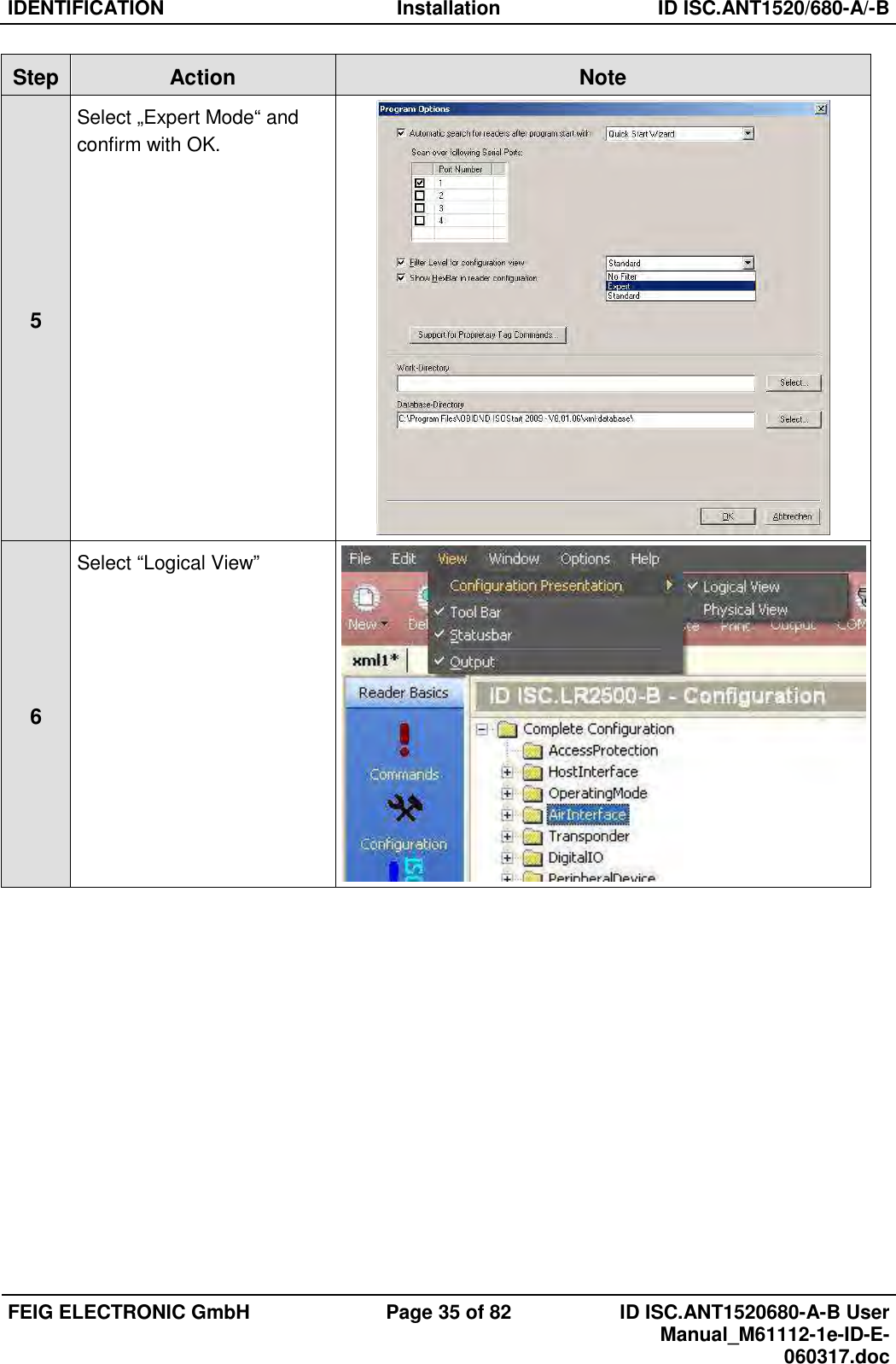
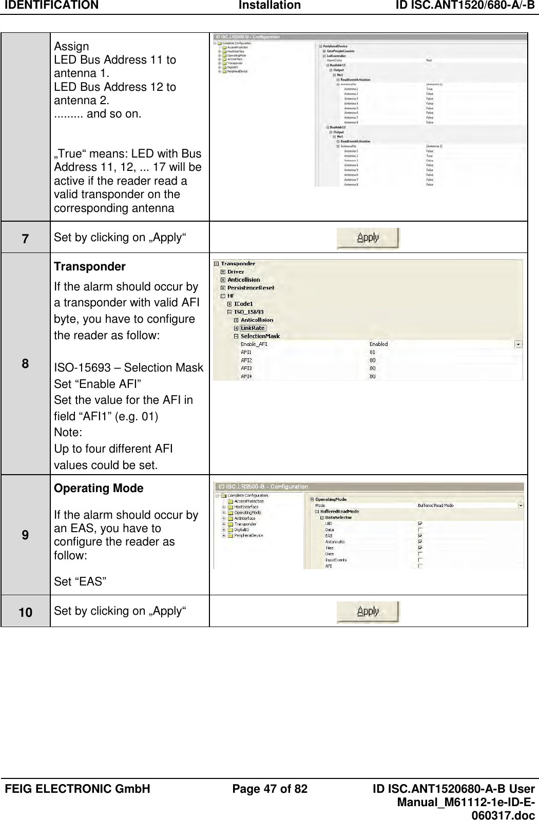
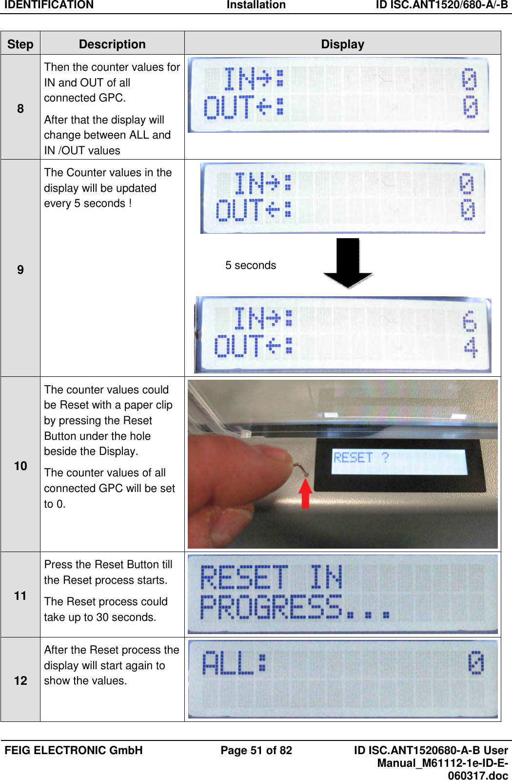
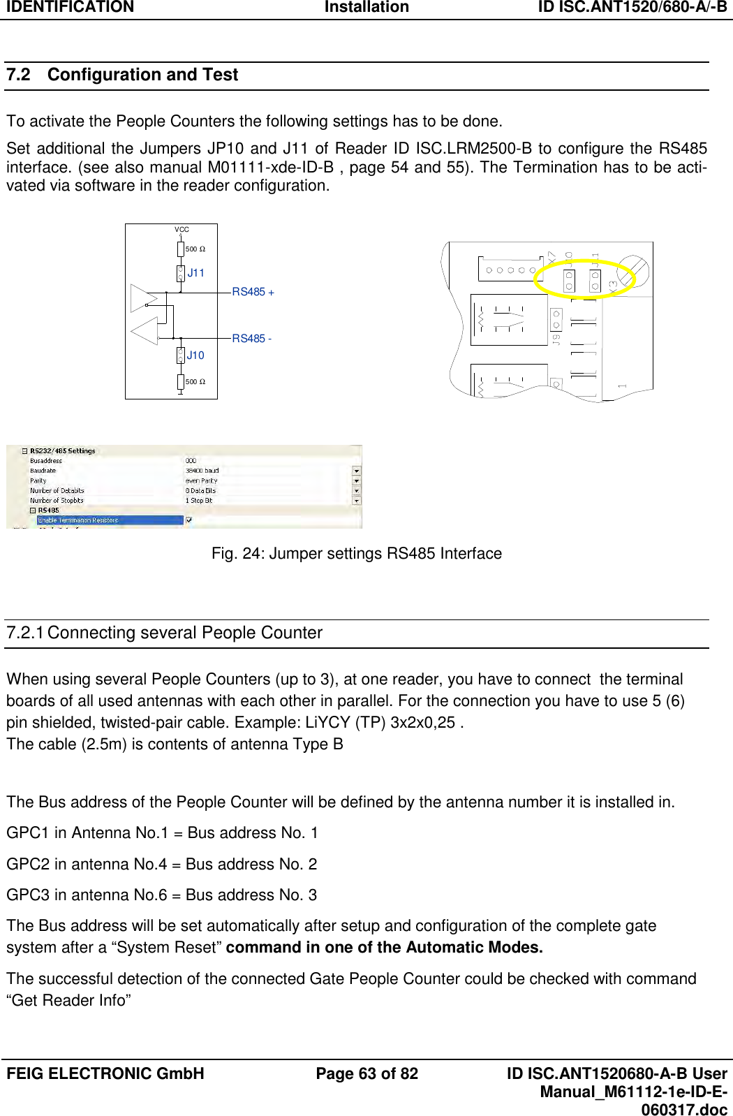
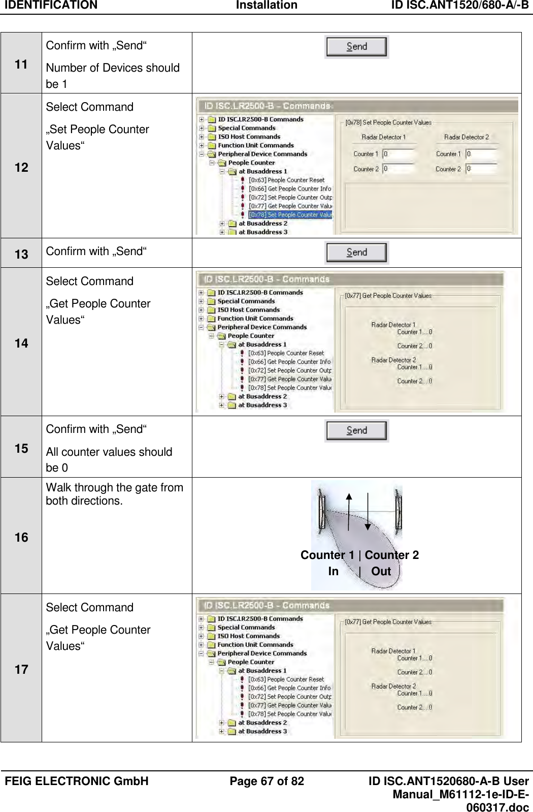
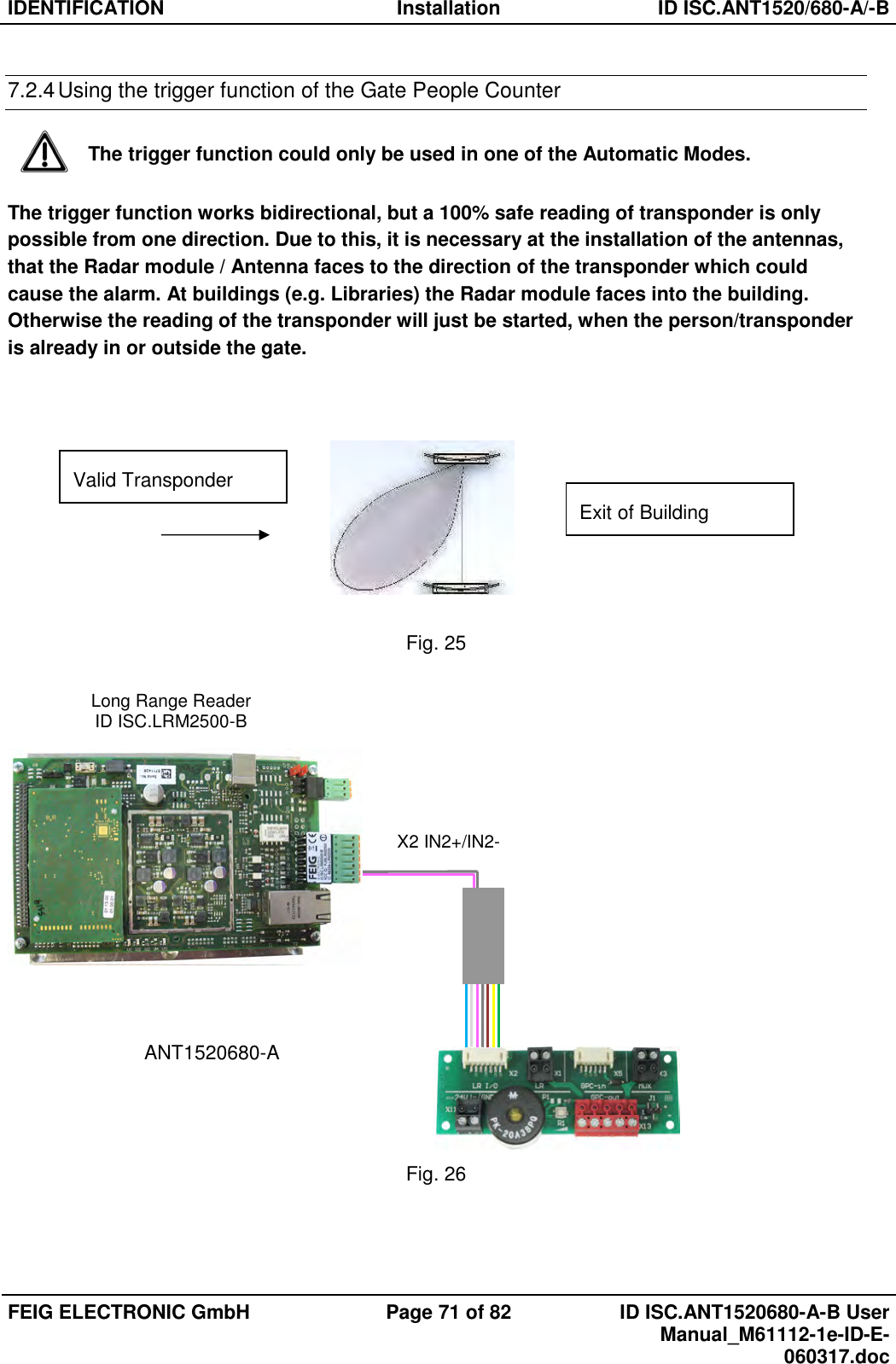
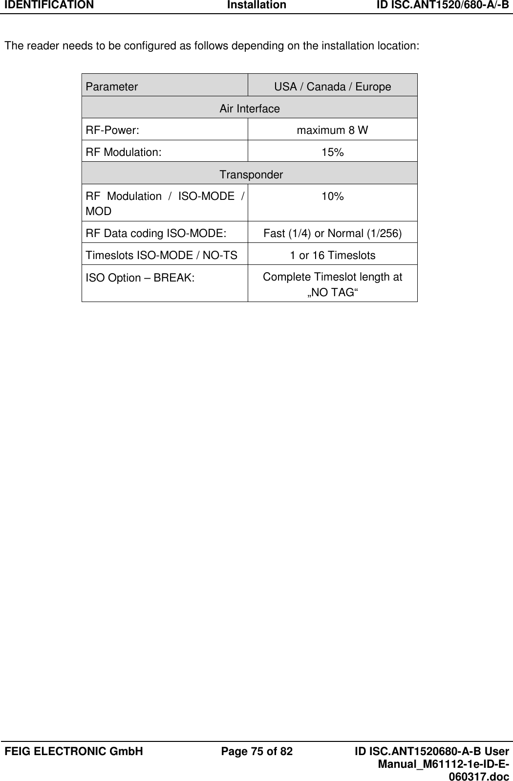
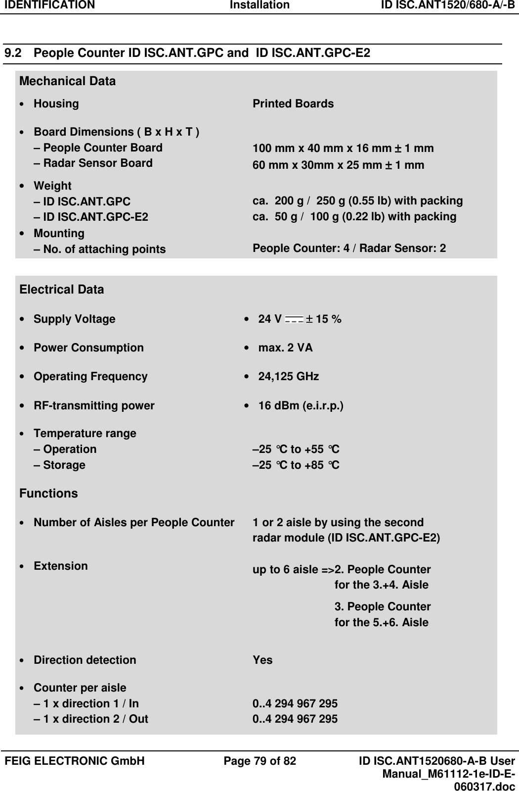
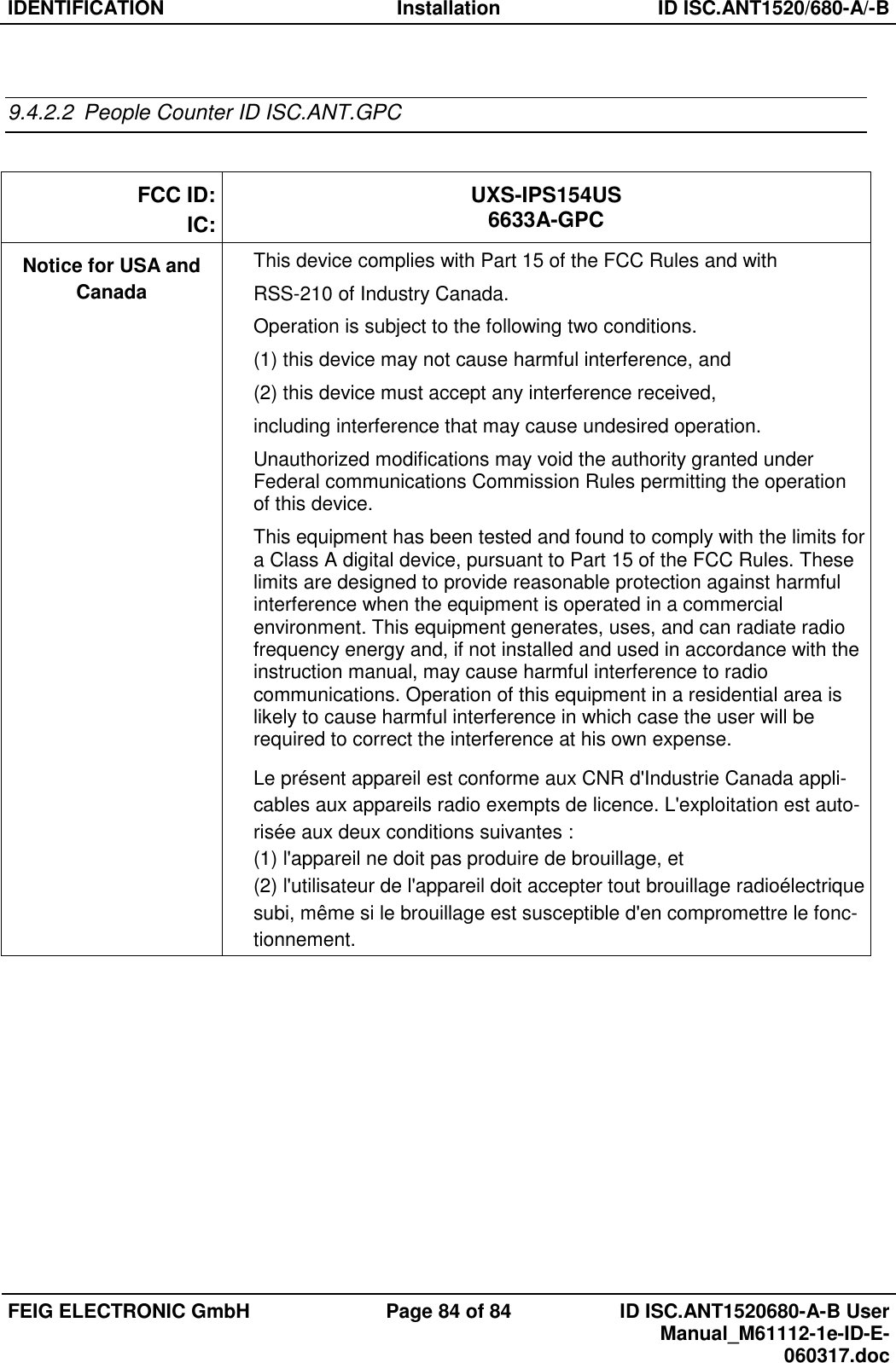
![IDENTIFICATION Installation ID ISC.ANT1520/680-A/-B FEIG ELECTRONIC GmbH Page 48 of 82 ID ISC.ANT1520680-A-B User Manual_M61112-1e-ID-E-060317.doc 6.5.4 Programming a Transponder with the AFI Byte If the Transponders will remain on the object when leaving the storage location, they must first be disabled. This is generally done by writing to a particular area of the Transponder. The AFI byte (Application Family Identifier) is useful for this purpose, since it is contained in nearly all Transponder models in the ISO15693 family. To disable, simply write a different code to the Transponder than for valid Transponders which trigger an alarm. Step Action: Note: 1 Select „Commands“ 2 Place the Transponder in the antenna field (Antenna 1) Select [0x01] Inventory Mode: “New Inventory Requested “ 3 Read UID by clicking on „Send“ 4 The serial number, DSFID and Transponder type are displayed in a window. Write down the serial number of the Transponder 5 Select „[0x27] Write AFI“ ADR: 1: addressed Serial Number: Select Transponder UID AFI: Desired AFI Number (not equal to 00) 6 Write AFI byte on to the transponder by click on „Send“](https://usermanual.wiki/Feig-Electronic/LRM2500.Users-Manual/User-Guide-3314321-Page-49.png)
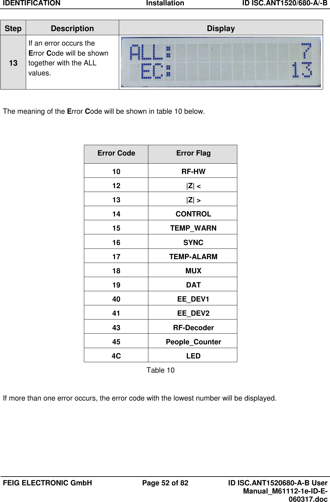
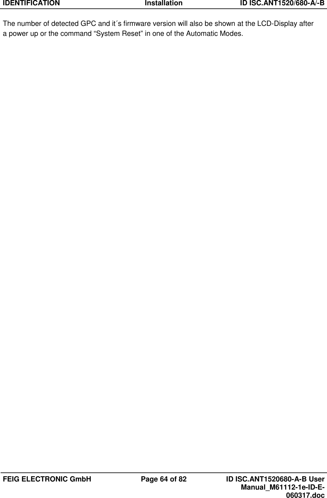
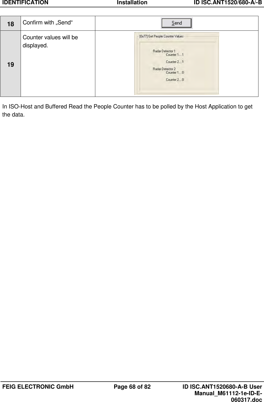
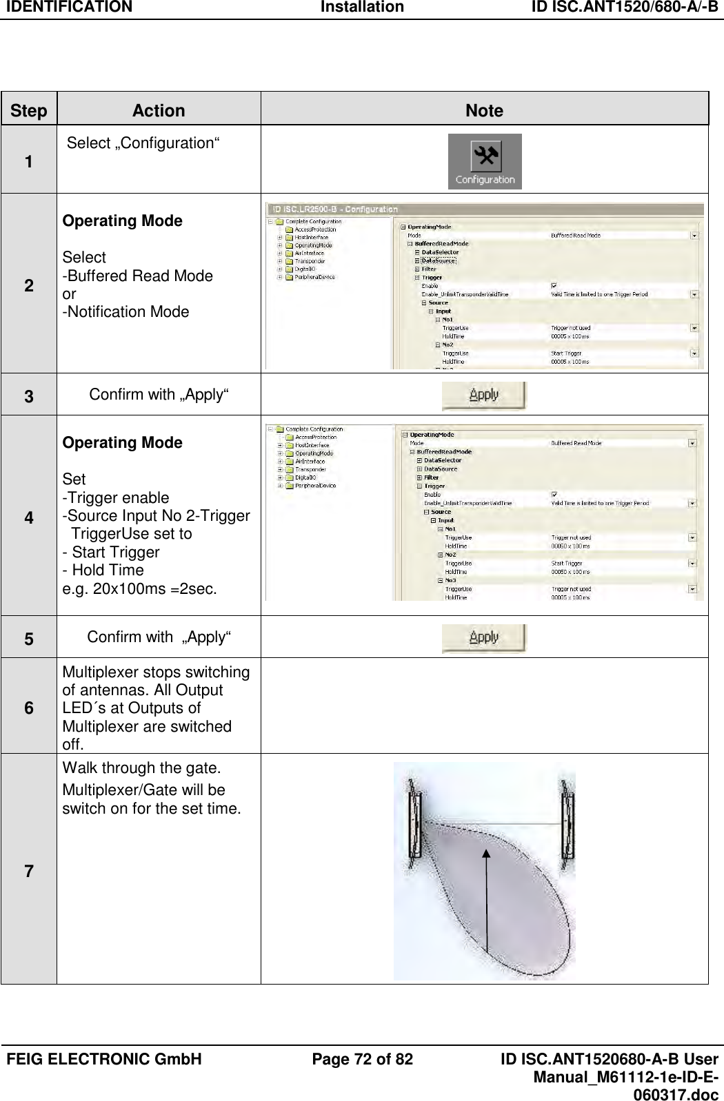
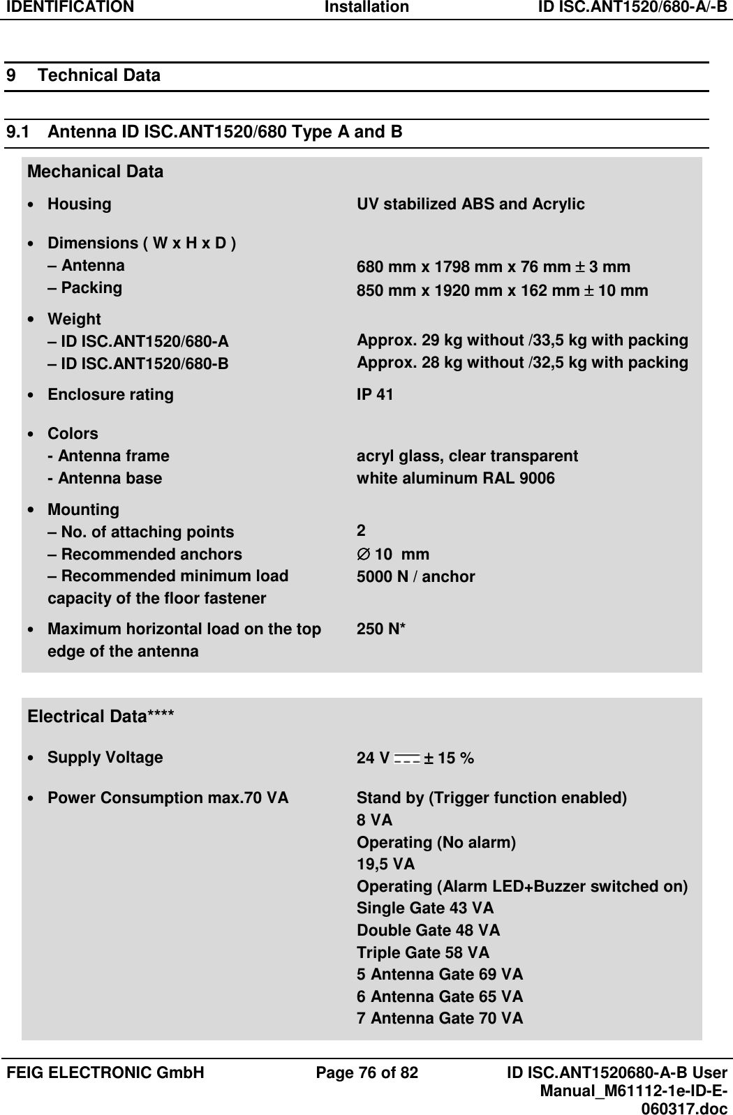
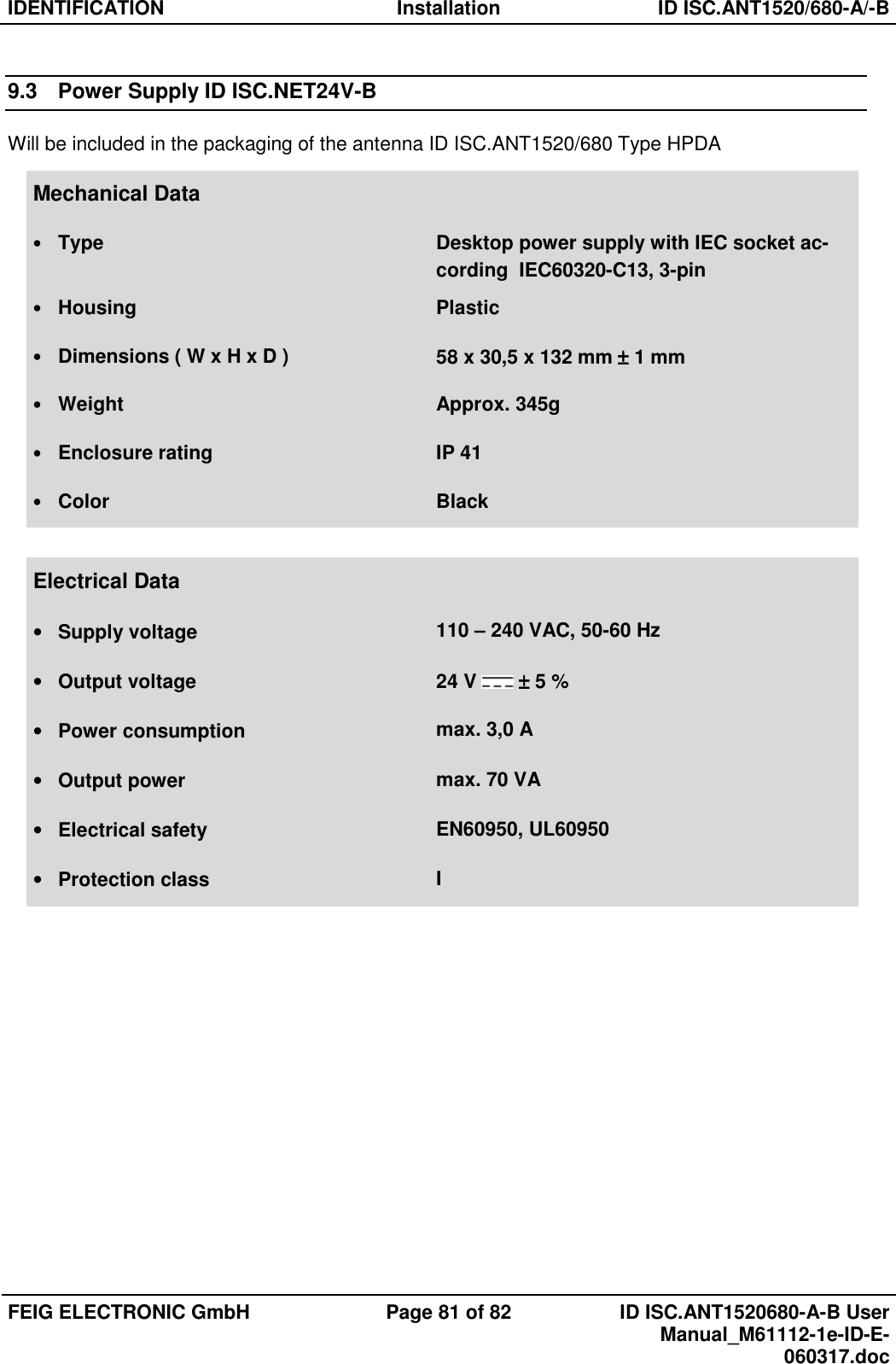
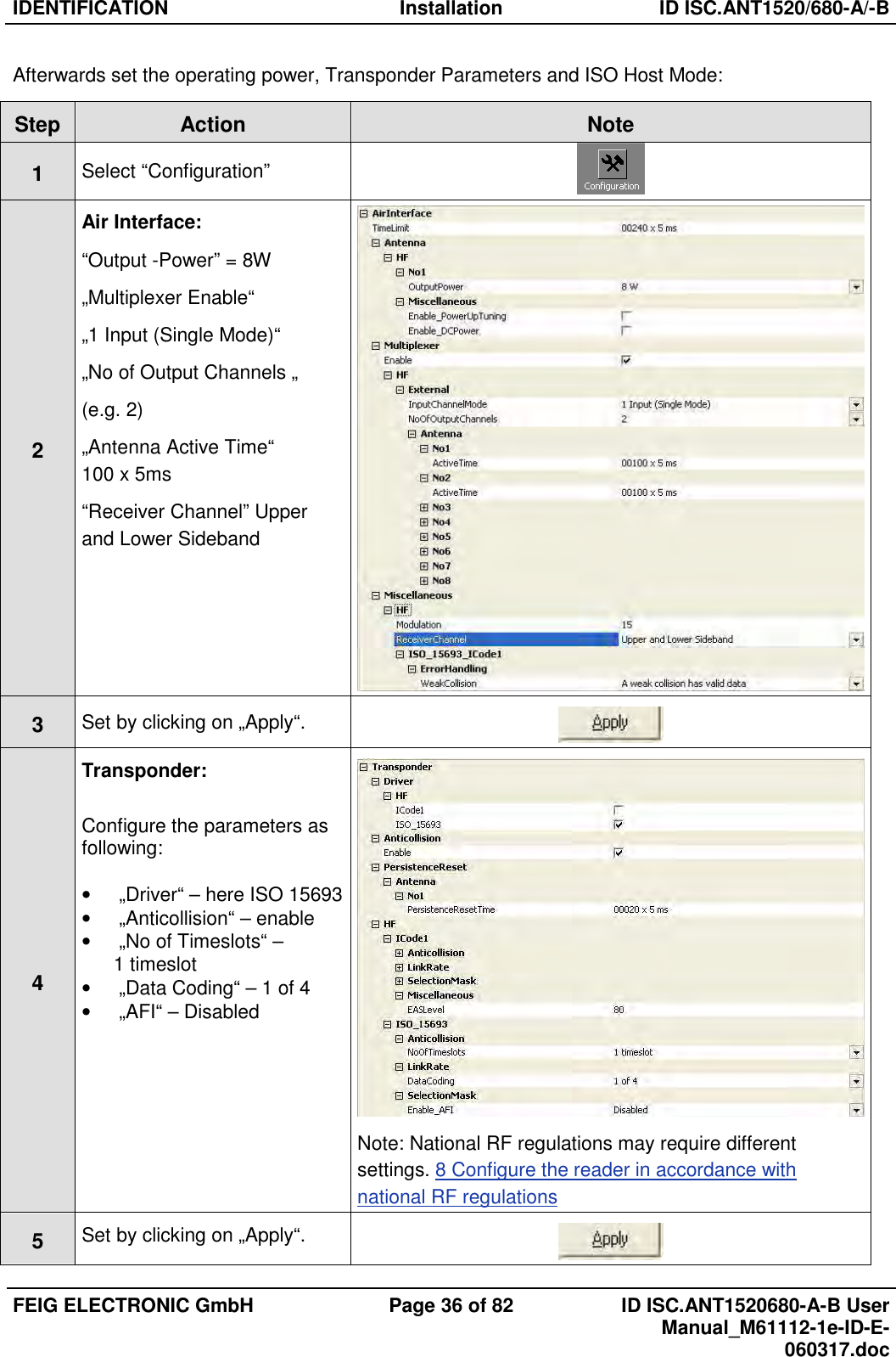
![IDENTIFICATION Installation ID ISC.ANT1520/680-A/-B FEIG ELECTRONIC GmbH Page 49 of 82 ID ISC.ANT1520680-A-B User Manual_M61112-1e-ID-E-060317.doc 7 To verify, read AFI byte by using the command [0x2B] Get System Information](https://usermanual.wiki/Feig-Electronic/LRM2500.Users-Manual/User-Guide-3314321-Page-50.png)