Feig Electronic LRM2500 ID ISC.ANT1520/680 (RFID gate) User Manual Testreport ETS 300 335
Feig Electronic GmbH ID ISC.ANT1520/680 (RFID gate) Testreport ETS 300 335
Contents
- 1. User Manual
- 2. User Manual II
- 3. Users Manual
Users Manual

Test report no. 17010729 Page 1 of 1
EUT: ID ISC.ANT1520/680 (RFID gate)
FCC ID:
PJMLRM2500
FCC Title 47 CFR Part 15
Date of issue: 2017-03-03
Date: 2016-08-19
Created: P9 Controlled: P4 Released: P1
Vers. no. 2.16
m. dudde hochfrequenz-technik
Rottland 5a
D-51429 Bergisch Gladbach/ Germany
Tel: +49 2207-96890
Fax +49 2207-968920
Annex acc. to FCC Title 47 CFR Part 15
relating to
Feig Electronic GmbH
ID ISC.ANT1520/680 (RFID gate)
Annex no. 5
User Manual
Functional Description
Title 47 - Telecommunication
Part 15 - Radio Frequency Devices
Subpart C – Intentional Radiators
ANSI C63.4-2014
ANSI C63.10-2013
INSTALLATION
Draft – custmized (E)
2017-03-06 –ID ISC.ANT1520680-A-B User Manual_M61112-1e-ID-E-060317.doc
ID ISC.ANT1520/680
Type A and B
/ RFID Gate
Version: Reader ID ISC.LRM2500-B

IDENTIFICATION Installation ID ISC.ANT1520/680-A/-B
FEIG ELECTRONIC GmbH Page 2 of 82 ID ISC.ANT1520680-A-B User
Manual_M61112-1e-ID-E-
060317.doc
Note
Copyright 2017 by
FEIG ELECTRONIC GmbH
Lange Strasse 4
D-35781 Weilburg
Tel.: +49 6471 3109-0
http://www.feig.de
With the edition of this document, all previous editions become void. Indications made in this manual may be
changed without previous notice.
Copying of this document, and giving it to others and the use or communication of the contents thereof are
forbidden without express authority. Offenders are liable to the payment of damages. All rights are reserved
in the event of the grant of a patent or the registration of a utility model or design.
Composition of the information in this document has been done to the best of our knowledge. FEIG
ELECTRONIC GmbH does not guarantee the correctness and completeness of the details given in this
manual and may not be held liable for damages ensuing from incorrect or incomplete information. Since,
despite all our efforts, errors may not be completely avoided, we are always grateful for your useful tips.
The instructions given in this manual are based on advantageous boundary conditions. FEIG ELECTRONIC
GmbH does not give any guarantee promise for perfect function in cross environments and does not give
any guaranty for the functionality of the complete system which incorporates the subject of this document.
FEIG ELECTRONIC call explicit attention that devices which are subject of this document are not designed
with components and testing methods for a level of reliability suitable for use in or in connection with surgical
implants or as critical components in any life support systems whose failure to perform can reasonably be
expected to cause significant injury to a human. To avoid damage, injury, or death, the user or application
designer must take reasonably prudent steps to protect against system failures.
FEIG ELECTRONIC GmbH assumes no responsibility for the use of any information contained in this docu-
ment and makes no representation that they free of patent infringement. FEIG ELECTRONIC GmbH does
not convey any license under its patent rights nor the rights of others.
OBID® and OBID i-scan® are registered trademarks of FEIG ELECTRONIC GmbH.
my-d® is a registered trademark of Infineon Technologies AG
I-CODE® is a registered trademark of Philips Electronics N.V.
Tag-itTM is a registered trademark of Texas Instruments Incorporated.

IDENTIFICATION Installation ID ISC.ANT1520/680-A/-B
FEIG ELECTRONIC GmbH Page 3 of 82 ID ISC.ANT1520680-A-B User
Manual_M61112-1e-ID-E-
060317.doc
General information's regarding this document
• The sign "" indicates extensions or changes of this manual compared with the former issue.
• If bits within one byte are filled with "-", these bit spaces are reserved for future extensions or
for internal testing- and manufacturing-functions. These bit spaces must not be changed, as this
may cause faulty operation of the reader.
• The following figure formats are used:
0...9: for decimal figures
0x00...0xFF: for hexadecimal figures,
b0...1 for binary figures.
• The hexadecimal value in brackets "[ ]" marks a control byte (command).

IDENTIFICATION Installation ID ISC.ANT1520/680-A/-B
FEIG ELECTRONIC GmbH Page 4 of 82 ID ISC.ANT1520680-A-B User
Manual_M61112-1e-ID-E-
060317.doc
Contents
1 Safety Instructions / Warning - Read before Start-Up ! 6
2 Instruction on transportation and shipping of the antennas 7
3 Maintenance 8
4 Performance Features of the ID ISC.ANT15200/680 Antennas 9
4.1 Performance Features of the People Counter ID ISC.ANT.GPC ............................ 10
4.2 Available Antenna Types ......................................................................................... 13
5 Installation and Wiring 14
5.1 Mounting Preparation .............................................................................................. 15
5.2 Installing the antenna ............................................................................................... 16
5.2.1 Dimensions of antenna ........................................................................................... 16
5.2.2 Drilling the Mounting Holes .................................................................................... 16
5.2.3 Installing the Antenna Base and Antenna Body ...................................................... 18
6 Typical Antenna Configuration (Gate Antenna with two Antennas) 19
6.1 Project Notes Antenna ............................................................................................. 19
6.2 Project Notes People Counter (GPC) ...................................................................... 22
6.3 Gate Configuration and Setup using Antennas ...................................................... 24
6.3.1 Required Components ........................................................................................... 24
6.3.2 Configuration of a Gate Antenna with Multiplexer ................................................... 25
6.3.3 Setting the Multiplexer ............................................................................................ 30
6.3.4 Interface Connections ............................................................................................ 31
6.3.4.1 LAN / TCP/IP ................................................................................................ 31
6.3.5 Reader Configuration with Multiplexer .................................................................... 32
6.3.6 Tuning the Gate Antenna ....................................................................................... 35
6.4 Testing the Gate Antenna......................................................................................... 37
6.4.1 Checking the Noise Level ....................................................................................... 37
6.4.2 Reading a Serial Number ....................................................................................... 39
6.4.3 Testing the performance ........................................................................................ 40
6.5 Setting the Alarm indicators (Alarm Buzzer and Alarm LED´s) ............................. 42
6.5.1 Setting the Buzzer .................................................................................................. 42

IDENTIFICATION Installation ID ISC.ANT1520/680-A/-B
FEIG ELECTRONIC GmbH Page 5 of 82 ID ISC.ANT1520680-A-B User
Manual_M61112-1e-ID-E-
060317.doc
6.5.2 Setting the LED´s ................................................................................................... 43
6.5.3 Reader Setting for Alarm Indicators ........................................................................ 44
6.5.4 Programming a Transponder with the AFI Byte ...................................................... 46
6.6 Functions of the LCD-Display .................................................................................. 48
6.7 Activating the Automatic Mode................................................................................ 51
6.8 Installation ID ISC.ANT.GPC-E2 ............................................................................... 52
7 Installation of the Gate People Counter ID ISC.ANT.GPC in antenna Type B 54
7.1 Installation and Connections ................................................................................... 54
7.2 Configuration and Test ............................................................................................. 60
7.2.1 Connecting several People Counter ....................................................................... 60
7.2.2 Configuration and Test in ISO-Host or Buffered Read ............................................ 61
7.2.3 Configuration and Test in Notification Mode ........................................................... 65
7.2.4 Using the trigger function of the Gate People Counter............................................ 67
7.2.5 Using the direction detection of transponder with the People Counter .................... 69
8 Configure the reader in accordance with national RF regulations 70
9 Technical Data 72
9.1 Antenna ID ISC.ANT1520/680 Type A and B ........................................................... 72
9.2 People Counter ID ISC.ANT.GPC and ID ISC.ANT.GPC-E2 ................................... 75
9.3 Power Supply ID ISC.NET24V-B............................................................................... 76
9.4 Approvals .................................................................................................................. 77
9.4.1 Europe (CE) ........................................................................................................... 77
9.4.1.1 Antenne ID ISC.ANT1520/680 ...................................................................... 77
9.4.1.2 People Counter ID ISC.ANT.GPC ............................................................... 77
9.4.2 USA (FCC) and Canada (IC) .................................................................................. 78
9.4.2.1 Antenna ID ISC.ANT1520/680 ...................................................................... 78
9.4.2.2 People Counter ID ISC.ANT.GPC ................................................................ 79
9.4.3 USA and Canada (UL) ........................................................................................... 80
10 Annex A 81
10.1 Terminal assignment “Terminal Board” .................................................................. 81
10.2 Internal wiring ........................................................................................................... 82

IDENTIFICATION Installation ID ISC.ANT1520/680-A/-B
FEIG ELECTRONIC GmbH Page 6 of 82 ID ISC.ANT1520680-A-B User
Manual_M61112-1e-ID-E-
060317.doc
1 Safety Instructions / Warning - Read before Start-Up !
• The device may only be used for the intended purpose designed by for the manufacturer.
• The operation manual should be conveniently kept available at all times for each user.
• Unauthorized changes and the use of spare parts and additional devices which have not been
sold or recommended by the manufacturer may cause fire, electric shocks or injuries. Such
unauthorized measures shall exclude any liability by the manufacturer.
• The liability-prescriptions of the manufacturer in the issue valid at the time of purchase are valid
for the device. The manufacturer shall not be held legally responsible for inaccuracies, errors,
or omissions in the manual or automatically set parameters for a device or for an incorrect
application of a device.
• Repairs may only be executed by the manufacturer.
• Installation, operation, and maintenance procedures should only be carried out by qualified
personnel.
• Use of the device and its installation must be in accordance with national legal requirements
and local electrical codes .
• When working on devices the valid safety regulations must be observed.
• Please observe that some parts of the device may heat severely.
• Before touching the device, the power supply must always be interrupted. Make sure that the
device is without voltage by measuring. The fading of an operation control (LED) is no indicator
for an interrupted power supply or the device being out of voltage!
• For installation and dismantling you should wear suitable safety gloves, because parts of an-
tenna housing could be sharp-edged.
CAUTION! The Antenna-Tuner and the Antenna conductor carry voltages up to
1000V.
The Antenna is not water proof and should not be exposed to rain or humidity.
Under extreme circumstances water could seep into the antenna and damage the electronic
circuits.
Special advice for wearers of cardiac pacemakers:
• Although this device doesn't exceed the valid limits for electromagnetic fields you should
keep a minimum distance of 25 cm between the device and your cardiac pacemaker and
not stay in an immediate proximity of the reader’s antennas for any length of time.
• CAUTION! Do not look directly into the Alarm LED light. There is a danger of
injury of the eyes!

IDENTIFICATION Installation ID ISC.ANT1520/680-A/-B
FEIG ELECTRONIC GmbH Page 7 of 82 ID ISC.ANT1520680-A-B User
Manual_M61112-1e-ID-E-
060317.doc
IDENTIFICATION Installation ID ISC.ANT1520/680-A/-B
FEIG ELECTRONIC GmbH Page 8 of 82 ID ISC.ANT1520680-A-B User
Manual_M61112-1e-ID-E-
060317.doc
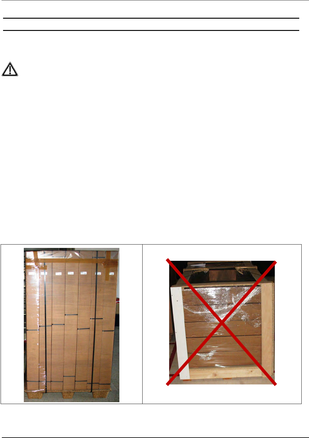
2 Instruction on transportation and shipping of the antennas
The packaging of the antennas has been designed to transport antennas vertically standing on a
pallet to the site of installation.
Attention! The antenna has be transported vertically on the base side on the pallet. A
transporting or storing in the false orientation can cause damaging at the antenna.
In case a vertically positioned transport is not possible, the antenna can be transported lying on the
narrow side. A transporting lying on its wide /flat side of the packaging can cause damage to the
device.
The pallet has to be adapted to the size and the number of antennas. In no case shall the
packaging stand out of the range. An additional protection of the edges of the pallet is recom-
mended.
The packaging mustn’t be moist at all times. When transporting overseas by ship or plane, the
packaging has to be protected against get damp at any time.
Temperatures above or below the specified temperature range may damage the antenna and / or
the packaging.
Any mechanical stress on the packaging is not permitted. Any stacking of packaging, can cause
damaging in the packaging below.
Even after the unpacking of the antennas the face of the antenna plate must be always transported
and stored vertically. A transport in horizontally oriented antenna can deform the antenna plate.

IDENTIFICATION Installation ID ISC.ANT1520/680-A/-B
FEIG ELECTRONIC GmbH Page 9 of 82 ID ISC.ANT1520680-A-B User
Manual_M61112-1e-ID-E-
060317.doc
3 Maintenance
The antenna ID ISC.ANT1520/680 is a design product with high quality surfaces, and should al-
ways be handled with caution. The antenna was designed to work reliably and flawlessly for years
without special maintenance.
Attention! The surfaces should be cleaned with a clean, soft cloth dampened in a
dishwashing liquid – water solution. The use of alcohol, spirit, thinners, glass clean-
ers or other harsh cleaning liquids is prohibited and will damage the acrylic plate.
To improve the durability and the appearance, please follow the instructions below:
• Keep the antenna clean and take care the antenna is not scratched. Also regularly apply spe-
cific antistatic products for acrylic surfaces.
• Regularly remove dust and other impurities with a soft cloth and a solution of water with a little
dishwashing liquid.
• Keep the antenna dry. All kinds of moisture should be avoided during operation and storage.
Precipitation, humidity and liquids contain minerals that will corrode electronic circuits and
damaging transparent plastic parts.
• Protect the antenna from high temperatures. Mount the antenna away from heaters and other
heat sources. Operation under direct sunlight can cause extreme high temperatures and a fad-
ing cause of the surface.
• Avoid storing or operating the antenna at dirty or wet locations. The surfaces or electronic
components may be-damaging.
• Handle the device with care. Shocks may break internal circuit boards.
• Do not try to open the antenna during operation or outside maintenance periods. Non-
professional management can result in damage to the device.
If any device not working properly, please contact the appropriate representative.

IDENTIFICATION Installation ID ISC.ANT1520/680-A/-B
FEIG ELECTRONIC GmbH Page 10 of 82 ID ISC.ANT1520680-A-B User
Manual_M61112-1e-ID-E-
060317.doc
4 Performance Features of the ID ISC.ANT15200/680 Antennas
The ID ISC.ANT1520/680-A antenna is a version with integrated Dynamic Antenna Tuning Board
ID ISC.DAT , Long Range Reader ID ISC.LRM2500-B, 4-times Multiplexer Module
ID ISC.ANT.MUX M4, additional Alarm LED light, Alarm buzzer and LCD Display.
Additionally, one People Counter and one radar Detector are already integrated in the antenna
ID ISC.ANT1520/680-A.
The ID ISC.ANT1520/680 Type B antenna is a version with integrated Dynamic Antenna Tuning
Board ID ISC.DAT and Alarm LED light mounted, only.
Up to
- two antennas with reader and multiplexer as a single gate,
- three to four antennas with reader and multiplexer as a double gate or triple gate
- up to 7 antennas as multiple gate with up to 6 aisle at the use of the 8-times Multiplexer
ID ISC.ANT-MUX M8.
can be operated.
Depending on the antenna configuration, one, two or all three read orientations of the Smart Tags
and various aisle widths (gate widths) are possible.
The ID ISC.ANT1520/680-A/B is a „figure-of-eight“ antenna with tuner and has been optimized as
transmitting and receiving antennas for the ID ISC.LRM2500 Reader. It is however also possible to
operate them with other readers at a transmission frequency of 13.56 MHz and an output
impedance of 50 Ω. The read ranges indicated in this document and the tuning procedures may
vary.
The antennas comprise the electrical antenna conductor, the housing, the ID ISC.DAT Dynamic
Antenna Tuner and the connection cables. The antennas are tuned to the factory default to an
impedance of 50 Ω in a magnetically neutral environment at a distance of 95 cm. When installing in
different ambient conditions the antenna can be retuned using the “DATuningTool“ PC software.
After tuning, the antennas will retain their settings as long as the ambient conditions remain
unchanged.
The antennas can be used for detecting both product and persons. It is for indoors use, only.
IDENTIFICATION Installation ID ISC.ANT1520/680-A/-B
FEIG ELECTRONIC GmbH Page 11 of 82 ID ISC.ANT1520680-A-B User
Manual_M61112-1e-ID-E-
060317.doc
4.1 Performance Features of the People Counter ID ISC.ANT.GPC
The product ID ISC.ANT.GPC, short form “Gate People Counter” or “GPC”, are made for mount-
ing in the gate antennas ID ISC.ANT1520/680.
A Gate People Counter consist of a People Counter board (PC) and one Radar Detector! The
product ID ISC.ANT.GPC-E2 Extension Radar Detector is used to extend the People Counter to a
second gate aisles.
The People Counter has two counters per aisle. The values of the incoming and outgoing persons
will be separately captured.
Fig. 1: Gate People Counter Structure (2-3 antennas, 1-2 gate aisles)
A change of the counter values will be stored in the EEPROM of the People Counter board. By
sending the command “0x78 Set People Counter” the values could be set/reset to the needed
value.
The counter values will be sent every 5 seconds to the LCD Display.
People
Counter 1
Radar
Detector 1
Out / LED 1
ID ISC.ANT.GPC
-
E
2
Extension Radar Detector
(e.g. 2’cd aisle of the gate)
Radar
Detector 2
Gate antenna
ID ISC.ANT1520/680.GPC
Reader
LCD Display
IDENTIFICATION Installation ID ISC.ANT1520/680-A/-B
FEIG ELECTRONIC GmbH Page 12 of 82 ID ISC.ANT1520680-A-B User
Manual_M61112-1e-ID-E-
060317.doc
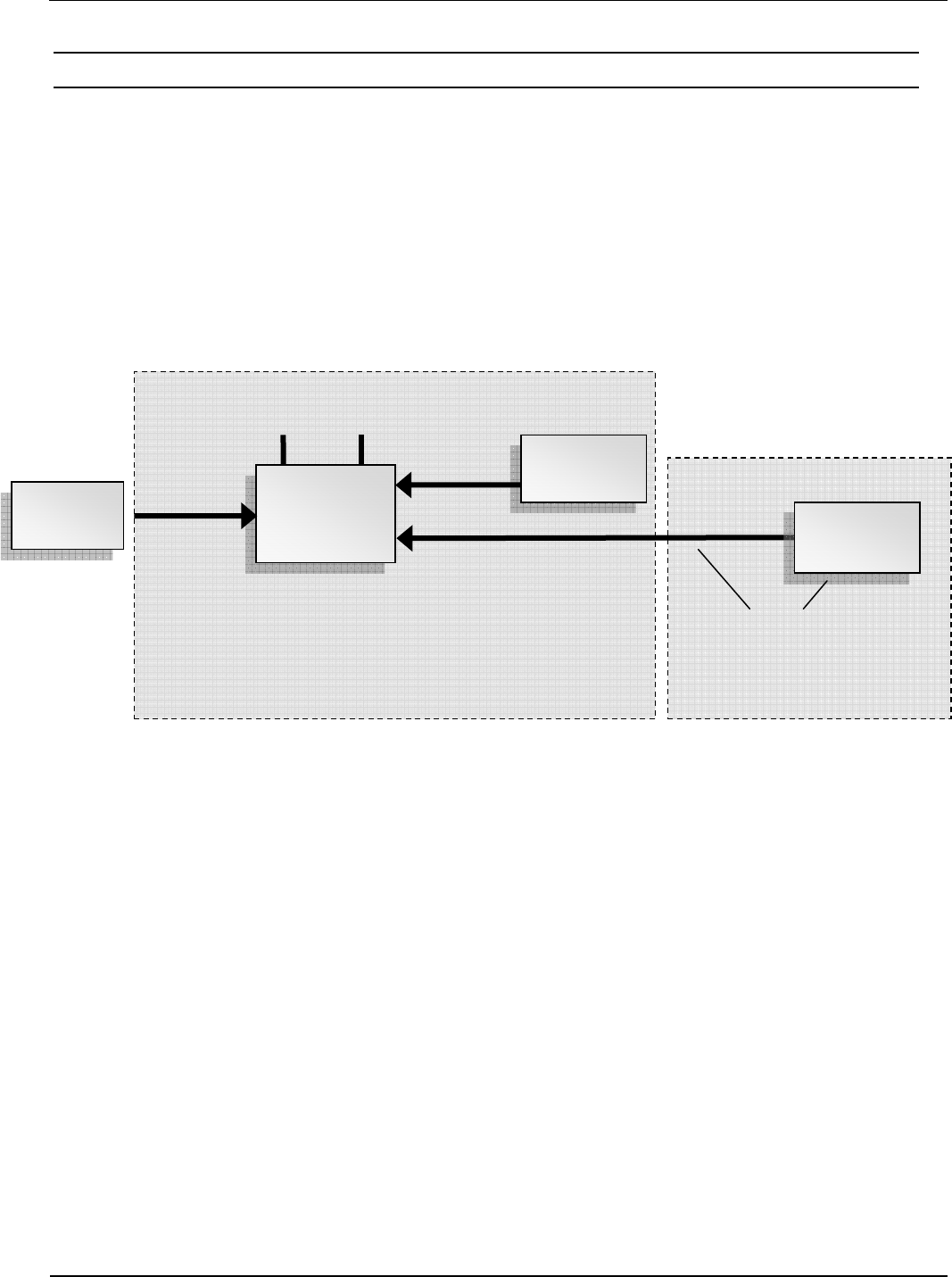
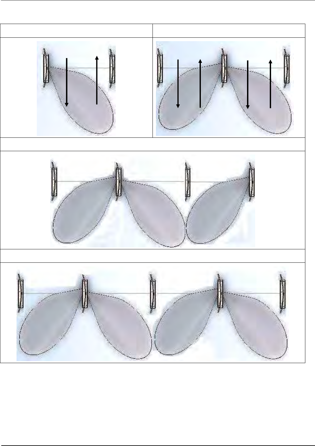
Radar detection zone of a single gate Radar detection zone with two aisles
Radar detection zone with three aisles
Radar detection zone with four aisles
Fig. 2: Top view of the detection areas (2-5 antennas, 1-4 gate aisles)
The People Counter board and the Radar detectors are mounted in the base of the antennas. Due
to the radar beam can pervade the plastic housing of the antenna, no openings a necessary.
The Connection between reader and people counter takes place through the RS485 Interface of
the reader, inside the antenna.
Counter 1 | Counter 2
In | Out
Cnt. 1 | Cnt. 2
In | Out
Cnt. 3 | Cnt. 4
In | Out

IDENTIFICATION Installation ID ISC.ANT1520/680-A/-B
FEIG ELECTRONIC GmbH Page 13 of 82 ID ISC.ANT1520680-A-B User
Manual_M61112-1e-ID-E-
060317.doc
There is no need of a direct connection from the GPC to the Host. All commands from the Host to
the People Counters are embedded in the Pickyback command (see H01011-2e-ID-B.pdf).
Generally, there are two possibilities to get the actual people counter values. Either the Host poll
the People Counter periodically or in the Notification Mode of the reader, the reader send a notifi-
cation protocol at every change.
In ISO Host or Buffered Read Mode, the host poll the GPC by sending protocols. Only, in the Noti-
fication Mode, the reader poll the counter values, automatically, and send data according the read-
er configuration to the host.
See also System Manual People Counter H01011-2e-ID-B.PDF
IDENTIFICATION Installation ID ISC.ANT1520/680-A/-B
FEIG ELECTRONIC GmbH Page 14 of 82 ID ISC.ANT1520680-A-B User
Manual_M61112-1e-ID-E-
060317.doc
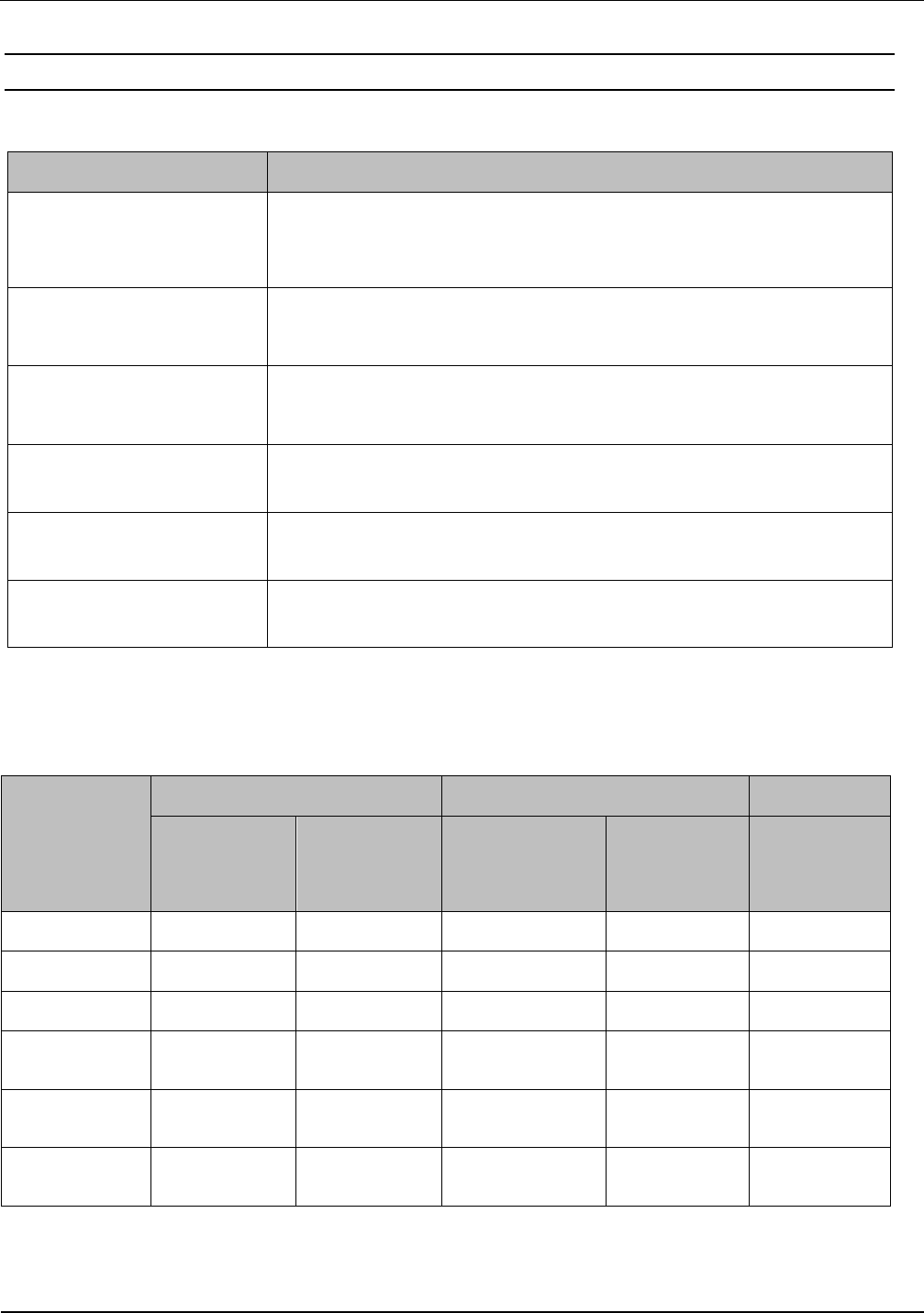
4.2 Available Antenna Types
The following products are currently available:
Antenna Type Description
ID ISC.ANT1520/680-A
Crystal Gate
Antenna with Reader, Multiplexer , dynamic tuning board
ID ISC.DAT, signal light, alarm buzzer, LCD display and People
Counter Board with one radar detector.
ID ISC.ANT1520/680-B
Crystal Gate
Antenna with dynamic tuning board ID ISC.DAT and signal light
ID ISC.ANT.GPC
Gate People Counter
People Counter, one piece of radar detector for antenna ID
ISC.ANT1520/680 incl. Mounting and cabling set. (optional)
ID ISC.ANT.GPC-E2
Extension Radar Detector
Second radar detector with cable for the second direct parallel aisle
(optional)
ID ISC.ANT.CRG-DT Crys-
tal Gate Drilling Template
Drilling Template and metal pad for soft ground. (optional)
ID ISC.ANT.CRG-MP Crys-
tal Gate Mounting Plate
Mounting plate for easy installation and metal pad for soft ground.
(optional)
Table 1: Available Antenna Types and Accessories
Required components to setup a gate by using the Gate People Counter:
Number of
antennas
Antenna People Counter (Optional)
ID ISC.
ANT1520/68
0
-A
ID ISC.
ANT1520/68
0
-B
ID ISC.
ANT1520/ 680-
GPC
ID ISC.ANT.
GPC-E2
Note
2 Antennas 1 1 0
3 Antennas 1 2 0 1
4 Antennas 1 3 1 1
5 Antennas 1 4 1 2 8 Chanel
Multiplexer
6 Antennas 1 5 2 2 8 Chanel
Multiplexer
7 Antennas 1 6 2 3 8 Chanel
Multiplexer
Table 2 Required components for gates with People Counter

IDENTIFICATION Installation ID ISC.ANT1520/680-A/-B
FEIG ELECTRONIC GmbH Page 15 of 82 ID ISC.ANT1520680-A-B User
Manual_M61112-1e-ID-E-
060317.doc
5 Installation and Wiring
Notes:
Before installing the antennas please read 6.1 Project Notes Antenna. The spacing of the
antennas in a gate depends on the antenna configuration.
If multiple antennas or gates are connected to different readers, a minimum clearance of
8 m must be kept between the antennas or gates. For shorter distances (1 m – 8 m) the
readers must be synchronized. The synchronization of the readers (see application note
N10311-xe-ID-B.doc) is only possible in one of the Automatic Modes (Buffered Read,
Notification or Scan Mode). Below a distance of 1.5 m the antennas must also be shielded
from each other. Otherwise the read range will be significantly reduced. The antennas must
have a minimum distance of 20 cm to all larger metal parts! At a distance of less than 50 cm
between the antenna and metal parts the read range will be significantly reduced.
IDENTIFICATION Installation ID ISC.ANT1520/680-A/-B
FEIG ELECTRONIC GmbH Page 16 of 82 ID ISC.ANT1520680-A-B User
Manual_M61112-1e-ID-E-
060317.doc
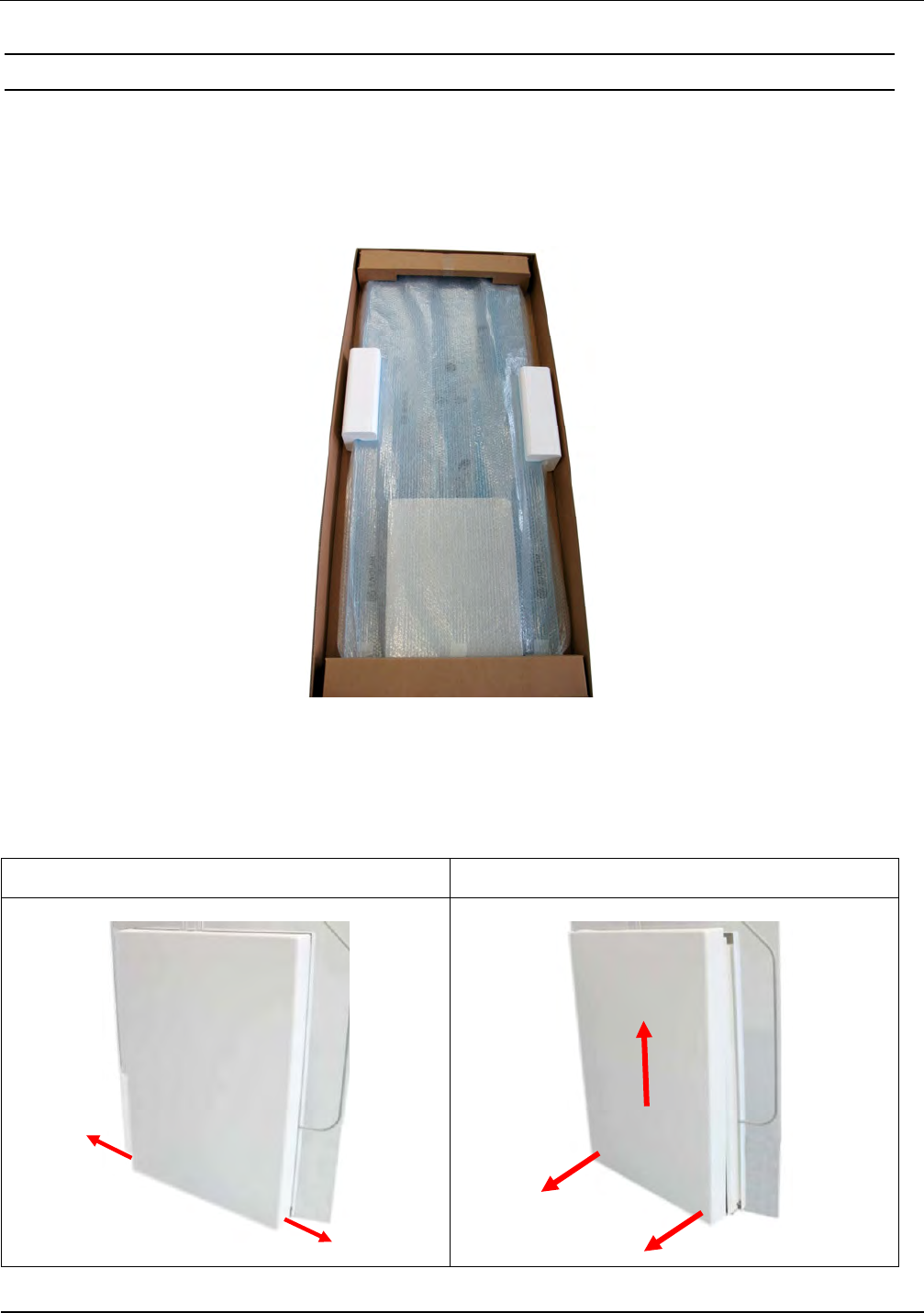
5.1 Mounting Preparation
For the assembly of the antenna it has to be carefully unpacked and the antenna base to be
opened. This is done as described in the following steps:
1. Place the packed antenna on the floor with the top side facing up. Carefully open the box and
then remove the antenna.
Fig. 3: Packed Antenna
2. Afterwards, the antenna has to be placed carefully on the floor again. Now, the two fastening
screws (hexagon socket width AF 2,5) have to remove of the antenna base cover. By moving
the cover upwards, carefully, remove the cover from the antenna base. Fig. 4
Step 1 Step 2
Fig. 4: Opening the antenna base
IDENTIFICATION Installation ID ISC.ANT1520/680-A/-B
FEIG ELECTRONIC GmbH Page 17 of 82 ID ISC.ANT1520680-A-B User
Manual_M61112-1e-ID-E-
060317.doc
5.2 Installing the antenna
5.2.1 Dimensions of antenna
The overall dimensions of the antenna are shown in Antenna outside dimensions
Antenna outside dimensions
All dimensions are in mm with general tolerance according to ISO 2768 m (mean).
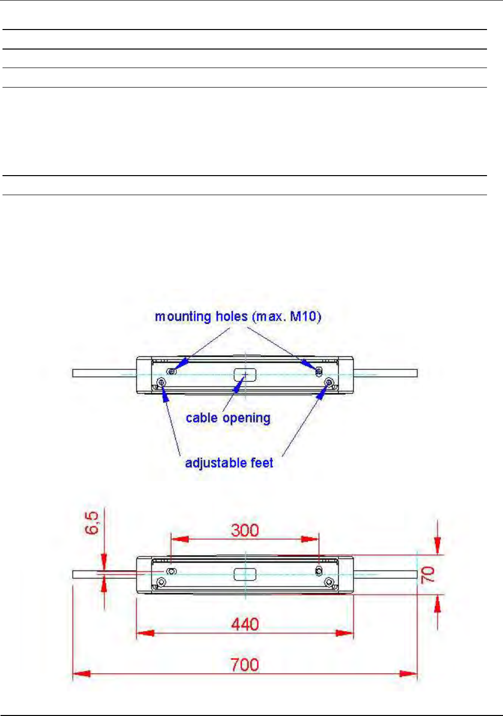
5.2.2 Drilling the Mounting Holes
If the position of the antennas has been marked or determined, the mounting holes and the holes
for the cable entry, can be marked and drilled. To make this easier the ID ISC.ANT.CRG-DT
Crystal Gate Drilling Template could be used.(optional). This Drilling template could also be used
for stabilization and weight distribution on soft grounds by mounting it additionally under the
antenna foot.The dimensions are shown in Fig. 5:
Fig. 5: Floor plate dimensions
IDENTIFICATION Installation ID ISC.ANT1520/680-A/-B
FEIG ELECTRONIC GmbH Page 18 of 82 ID ISC.ANT1520680-A-B User
Manual_M61112-1e-ID-E-
060317.doc
All dimensions are in mm with general tolerance to ISO 2768 m (middle).
The size and type of the anchors depends considerably on the strength of the base or floor. The
anchors should be capable of withstanding a permissible load of at least 5 kN per anchor for all
load directions (e.g. for concrete floor Hilti HVA anchors with HAS-(E) M8 threaded rod or Hilti HIS-
N M8 (5/16”) threaded inserts). The size of the mounting holes in the antenna is 10 mm (.39”). The
length of the anchors or bolts should be selected such so they jut out at least 40 mm (1.6”) and
maximum of 55 mm (2.2”) of the floor.
Please follow the mounting instructions of the anchor manufacturer!
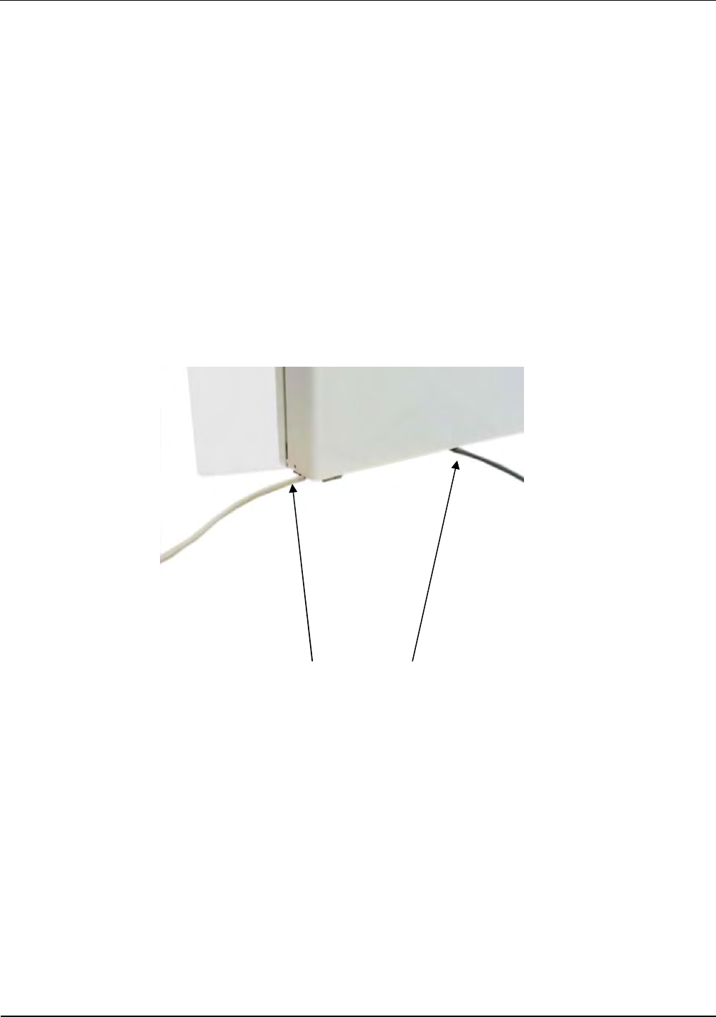
A cable opening is provided for the necessary connection cable (see Fig. 5). The cable opening is
dimensioned such as up to 10 cables having a diameter of 6 mm can be passed through the
opening.
Alternatively the cables can be routed at the sides of the antenna bas like shown in Fig. 6
Fig. 6 Cable routing at the antenna sides
IDENTIFICATION Installation ID ISC.ANT1520/680-A/-B
FEIG ELECTRONIC GmbH Page 19 of 82 ID ISC.ANT1520680-A-B User
Manual_M61112-1e-ID-E-
060317.doc
5.2.3 Installing the Antenna Base and Antenna Body
The antenna will be mounted on the floor. Please note, the antenna conductors in the middle of the
antenna body have to have the same direction (Fig. 7). Afterwards, the antenna has to be aligned
the antenna vertically, by using the adjusting screws (Fig. 8). Please read also 7.2.4 Using the
trigger function of the Gate People Counter and 6.2 Project Notes People Counter (GPC).
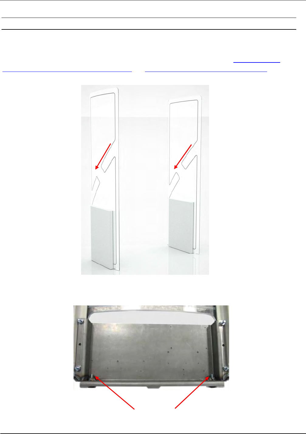
Fig. 7 Conductors shape have to have same direction
Adjusting screws (hexagon socket width AF 4)
Fig. 8: Attaching and aligning the antenna
IDENTIFICATION Installation ID ISC.ANT1520/680-A/-B
FEIG ELECTRONIC GmbH Page 20 of 82 ID ISC.ANT1520680-A-B User
Manual_M61112-1e-ID-E-
060317.doc
6 Typical Antenna Configuration (Gate Antenna with two Antennas)
The standard configuration of a gate with three-dimensional tag orientation consists of one
ID ISC.ANT1520/680-A with reader and multiplexer and one ID ISC.ANT1520/680-B. If a tag
moves, at horizontal line, through the gate, it can be read at least once. This ensures high reliability
of the antenna system.
6.1 Project Notes Antenna
The antenna configuration as described allows detection of a tag moving at a horizontal line,
through the reading area of the gate. The tag orientation is non-critical. The tags are detected
along a horizontal axis of motion in certain regions within the antennas. The area of detection
depends on the tag orientation.
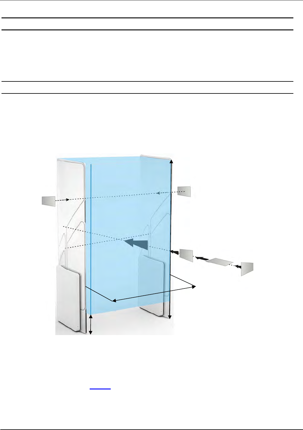
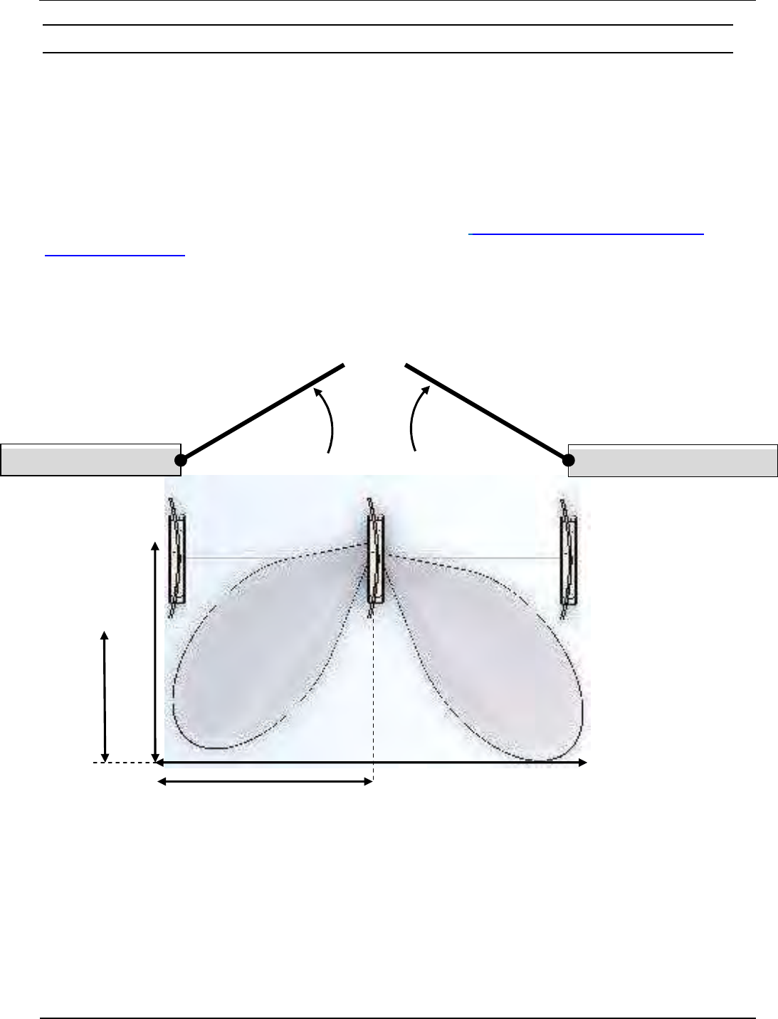
The size of the three-dimensional reading area of the antennas is shown in the sketch below.
Fig. 9: Capture area and tag orientation
Notes:
Note that the entire reading area of the antenna gate is larger than the three-dimensional
area shown in the drawing (Fig. 10). This means there are tag orientations in which the tag
can be detected outside the reading area.
To get a optimal performance the reader has to be configured and run in one of the
Automatic Modes (Buffered Read, Notification or Scan Mode).
GD
A= 20 cm
H= 180 cm
IDENTIFICATION Installation ID ISC.ANT1520/680-A/-B
FEIG ELECTRONIC GmbH Page 21 of 82 ID ISC.ANT1520680-A-B User
Manual_M61112-1e-ID-E-
060317.doc
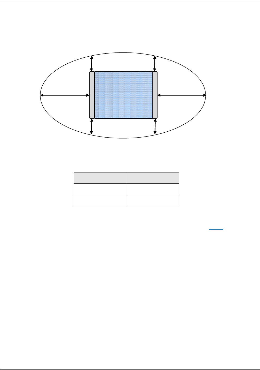
If multiple gates are arranged with short distances (1-8m) between each other, these will
mutually interfere with each other. In this case, the readers for the individual gates have to
be synchronized and run in one of the automatic modes.
Fig. 10: Top view, capture area outside of the antenna gate
Direction Minimum Distance
right, left (X=) 80 cm
front, behind (Y=) 40 cm
Table 3: Capture area, unintentional detection
To achieve three-dimensional reading of the tag in the reading area drawn above (Fig. 9), the
following conditions must be fulfilled:
- The gate distance (GD) depends on the antenna configuration (see Table 5: ).
- The tags should be at least ISO card size (46 mm x 75 mm).
- The activation field strength of the tags should be less than or equal to 60 mA/m.
- The distance from tag to tag should be greater than 10 cm. If the tag to tag distance is reduced,
the gate distance GD must be reduced correspondingly. This applies in particular to distances
under 5 cm.
- The maximum number of tags (serial number or data) depends on the traverse speed with
which the tags are brought through the capture area of the gate (see Table 5: ). The number of
tags may be increased in the gate distance GD is correspondingly reduced and the maximum
speed adjusted accordingly.
- The antenna should be at least 50 cm away from metal parts.
- The minimum distance between the antennas of a gate and other antennas of RFID work
station or terminals (transmitting frequency 13,56 MHz) should be:
X X
Y
Y
IDENTIFICATION Installation ID ISC.ANT1520/680-A/-B
FEIG ELECTRONIC GmbH Page 22 of 82 ID ISC.ANT1520680-A-B User
Manual_M61112-1e-ID-E-
060317.doc
Transmitted
output power
Minimum Distance
< 0.5 W 1 m
0.5 W-1.0 W 2 m
1.1 W – 2.0 W 3 m
> 2 W 4 m
>= 4 W 8 m
Table 4: Minimum Distances
- There should be no interference of the Reader from other electrical devices in the environment.
The Noise Level difference should be less than 20 mV.
- The ID ISC.LRM2500 reader should be set to an RF power of 8 watts.
- When using ISO 15693 transponders, the Readers should be set as described in 6.3.5 Reader
Configuration.
- If multiple gates are operated at the same time at a distance of less than 8 m, the Readers
must by synchronized. See Application Note Synchronizing RFID Long Range Readers using
the digital in-/outputs (N10311-xe-ID-B.pdf).
Gate with antenna
Type A and Type B
Gate distance GD ≤ 100 cm
Number of tags at a speed of
1 m/s
- Read serial number
- Read data
16
8
Table 5: Gate distance
Supplementary equipment (e.g. light barrier, lighting, etc.), mounted directly on the antenna or in
the immediate vicinity of the antenna can interference with the functioning of the system.
A minimum distance of 20 cm is required.
Electrical cable, directly at the antenna or in the immediate vicinity of the antenna, can be cause
interference. A minimum distance of 20 cm is required.
A minimum distance of 65cm between the two gate antennas is required.
IDENTIFICATION Installation ID ISC.ANT1520/680-A/-B
FEIG ELECTRONIC GmbH Page 23 of 82 ID ISC.ANT1520680-A-B User
Manual_M61112-1e-ID-E-
060317.doc
6.2 Project Notes People Counter (GPC)
The radar sensor of the People Counter detect moving objects within the detection area / beam
(A1, A2, see Fig. 11) of the radar antenna. The size of the detection area, and hence the sensitivity
of the devices can be adjusted with jumpers JP1 and JP2
A door (including glass doors), a curtain and in particular automatic doors or other moving objects
can influence the counting of the People Counter much.
If a People Counter is installed in the antenna, the antenna conductors in the middle of the antenna
body must be aligned, that the red arrows show, according to Fig. 7 (Conductors shape have to
have same direction) in the direction of free space.
That means, the antennas are installed close to the entrance and exit, the detection area of the
radar sensors must show away from the door. Otherwise, a minimum distance of 1.0 m between
moving objects and detection areas must be guaranteed.
Fig. 11: Top: Detection area A1 und A2 (Foot print) of the radar sensor
Antenna
Type -A
wall / masonry
wa
ll / masonry .
door
C
A
B
A1 A2
D
Typ -B Typ -B

IDENTIFICATION Installation ID ISC.ANT1520/680-A/-B
FEIG ELECTRONIC GmbH Page 24 of 82 ID ISC.ANT1520680-A-B User
Manual_M61112-1e-ID-E-
060317.doc
Sensitivity Low:
JP1+2 open
Medium:
JP1 closed
** High:
JP2 closed
Very high:
JP1+2 closed
Distance A 180 cm 200 cm 200 – 220 cm 240 - 260 cm
Distance B 60–70 cm 80-90 cm 100-110 cm 120 – 130 cm
Distance C 20-30 cm 40-50 cm 60-70 cm 80-90 cm
Distance D 90 cm 100 cm 100 – 110 cm 120 - 130 cm
Table 6: Detection area radar sensor, antenna distance 1m
** Standard configuration
All values are approximate, depending on the size of the objects, the behavioral reflection of the
floor and the material of the moving object.
If two people (or moving objects) move, simultaneously, in the detection area of one radar sensor,
usually, is counted one person, only.
The minimum distance between two people, so that these people are detected separately, as a
function of the adjusted sensitivity and position in the passage is 60 cm to 130 cm.
Cross traffic in the detection area, i.e. people who cross in front of the antennas, go from left to
right (or contrariwise), can also be counted or recorded.
To avoid interference, the detection area of radar motion detector, mounted above or at automatic
doors (Operating frequency 24.125 GHz), must not overlap with the detection area People
Counter.
The People Counter was designed to obtain statistical values on visitor flows. By people
with small distances, due to interferences, and by cross traffic, can vary the determined
values of the actual values.
If greater deviations are found, at first, the sensitivity of the radar sensors should be reduced
stepwise.

IDENTIFICATION Installation ID ISC.ANT1520/680-A/-B
FEIG ELECTRONIC GmbH Page 25 of 82 ID ISC.ANT1520680-A-B User
Manual_M61112-1e-ID-E-
060317.doc
6.3 Gate Configuration and Setup using Antennas
6.3.1 Required Components
To set up the gate you need the following components:
- Qty. 1 ID ISC.ANT1520/680-A Crystal Gate (Base)
(incl. Qty. 1 ID ISC.NET24V-B Power Supply Unit)
- Qty. 1 ID ISC. ANT1520/680-B Crystal Gate
- Power cable, interface cable and connection cable for the DC power supplies (2-wire,
twisted)
- Mounting materials (screws, anchors)
To calibrate the Reader you will need the software
- ISOStart 2017 Bibliotheca Version 09.09.09 or higher
and for tuning the antennas the service software
- DATuningTool Version 1.02.02 or higher
on a personal computer running under Microsoft® Windows®. The service can be downloaded at
the Download Area of the Homepage www.feig.de.
IDENTIFICATION Installation ID ISC.ANT1520/680-A/-B
FEIG ELECTRONIC GmbH Page 26 of 82 ID ISC.ANT1520680-A-B User
Manual_M61112-1e-ID-E-
060317.doc
6.3.2 Configuration of a Gate Antenna with Multiplexer
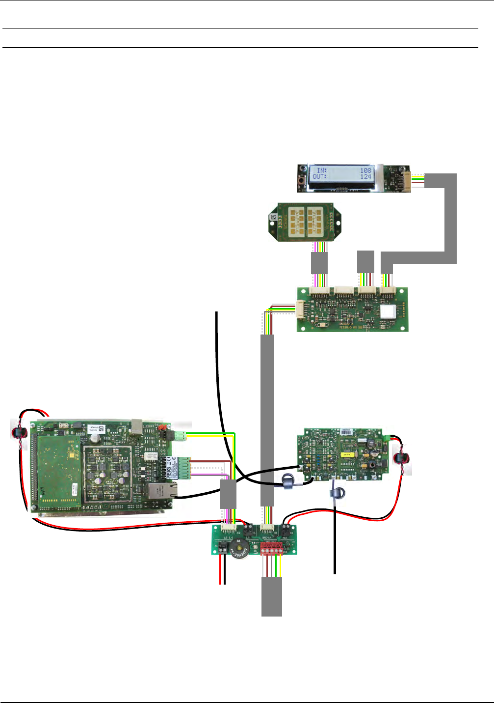
Connect the components as shown in Fig. 12 . Almost, all cable should be mounted already.
Normally, the antenna cable from antenna Type B has to be connected to OUT2 at the multiplexer
and the 24V DC power supply to X11 of the terminal board. Also a connection between
X13 GPC-out of the terminal board in Antenna Type A and X13 GPC-out of the terminal board in
Antenna Type B must be installed to supply the LED with power and RS485 Bus.
Fig. 12: Connecting the components for a gate consisting of two antennas, reader and multiplexer
LED1
1. Antenna
ID ISC.ANT.GPC
Gate People Counter
Radar Module 1
LCD-Display
X6
HF- Antenna A
135 cm
X1
8,55 m
IN
OUT 2
OUT 1
LED2
2. Antenna
DC Power
Supply24 V
X3
X2
Multiplexer
ID ISC.ANT.MUXM4
Long Range Reader
ID ISC.LRM2500-B
2. Antenna
ANT1
IDENTIFICATION Installation ID ISC.ANT1520/680-A/-B
FEIG ELECTRONIC GmbH Page 27 of 82 ID ISC.ANT1520680-A-B User
Manual_M61112-1e-ID-E-
060317.doc
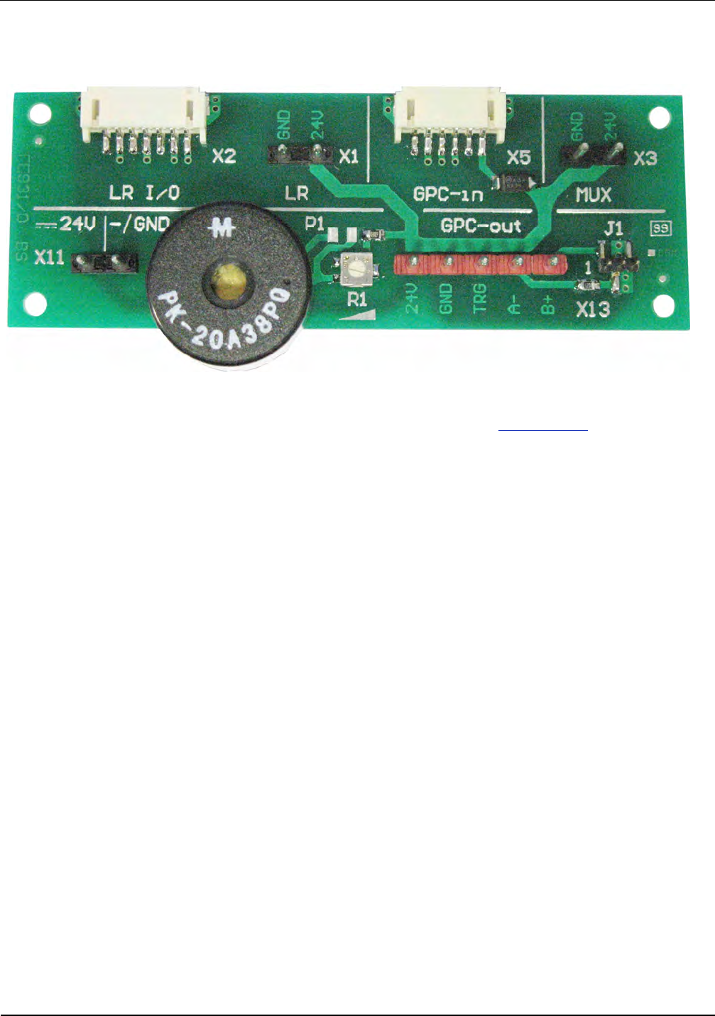
Fig. 13: Terminal board
An overview of the terminal board assignment is given in 10. Annex A
Note:
• A reverse polarity could damage the device or the In-/Outputs.
IDENTIFICATION Installation ID ISC.ANT1520/680-A/-B
FEIG ELECTRONIC GmbH Page 28 of 82 ID ISC.ANT1520680-A-B User
Manual_M61112-1e-ID-E-
060317.doc
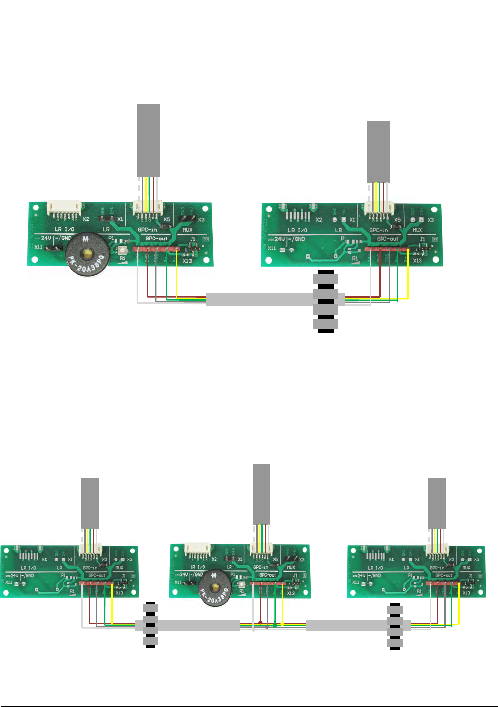
Find here the wire connection between antenna Type A and B
At a single gate with 2 antennas a connection between X13 GPC-out of the terminal board in
Antenna Type A and X13 GPC-out of the terminal board in Antenna Type B must be installed.
The side with the ferrite core must be placed in the antenna Type B.
Fig. 14 Connection between the antennas at a single gate
At a double gate with 3 antennas a connection between
X13 GPC-out of the terminal board in Antenna Type A and X13 GPC-out at the 1. Antenna Type B
and X13 GPC-out of the terminal board in Antenna Type A und X13 GPC-out at the 2. Antenna
Type B must be installed. The sides with the ferrite core must be placed in the antenna Type B.
Fig. 15 Connection between the antennas at a double gate
Basically X13 GPC-out of the terminal boards of all used antennas must be connected from
antenna to antenna 1:1 in parallel.
ANT1520680-B
ANT1520680-A
LED-light
1. People Counter
Antenna No.1
ANT1520680-A
LED
-
light
1. People Counter
LED
-
light
Antenna No.2
ANT1520680-B
Antenna No.3
ANT1520680-B
IDENTIFICATION Installation ID ISC.ANT1520/680-A/-B
FEIG ELECTRONIC GmbH Page 29 of 82 ID ISC.ANT1520680-A-B User
Manual_M61112-1e-ID-E-
060317.doc
The coax cables have fixed lengths and may not be shortened and therefore need to be tied into
small loops (see
Fig. 16). Tie all cables as far away from the antenna conductor as possible. The cables must never
be allowed to contact the antenna conductor. Unused cable length (e.g. of interface cable) should
not be placed in the area above the reader and multiplexer. The power supply should not be
placed in the type A antenna.

IDENTIFICATION Installation ID ISC.ANT1520/680-A/-B
FEIG ELECTRONIC GmbH Page 30 of 82 ID ISC.ANT1520680-A-B User
Manual_M61112-1e-ID-E-
060317.doc
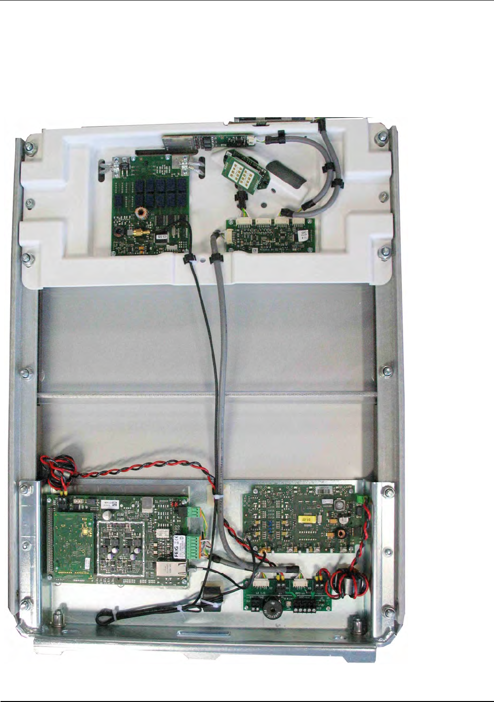
Fig. 16:Connection of the components in an antenna Type A
IDENTIFICATION Installation ID ISC.ANT1520/680-A/-B
FEIG ELECTRONIC GmbH Page 31 of 82 ID ISC.ANT1520680-A-B User
Manual_M61112-1e-ID-E-
060317.doc
The cable from antenna type B to the antenna type A should preferably be connected shortly.
Unused cable lengths are possible should be tied in antenna B type. Tie all cables as far away
from the antenna conductor as possible. The cables must never be allowed to contact the antenna
conductor. It is possible to place the power supply in foot of the antenna type B.
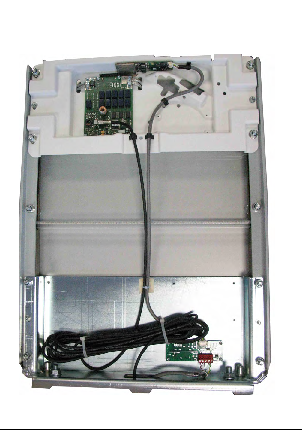
Fig. 17: Unused coaxial cables are tied in antenna Type B
IDENTIFICATION Installation ID ISC.ANT1520/680-A/-B
FEIG ELECTRONIC GmbH Page 32 of 82 ID ISC.ANT1520680-A-B User
Manual_M61112-1e-ID-E-
060317.doc
6.3.3 Setting the Multiplexer
The jumpers JP11-JP14 should be set (factory setting) as shown. More on setting the ID
ISC.ANT.MUX.M4 Multiplexer can be found in the corresponding installation manual
(M90700-xde-ID-B).
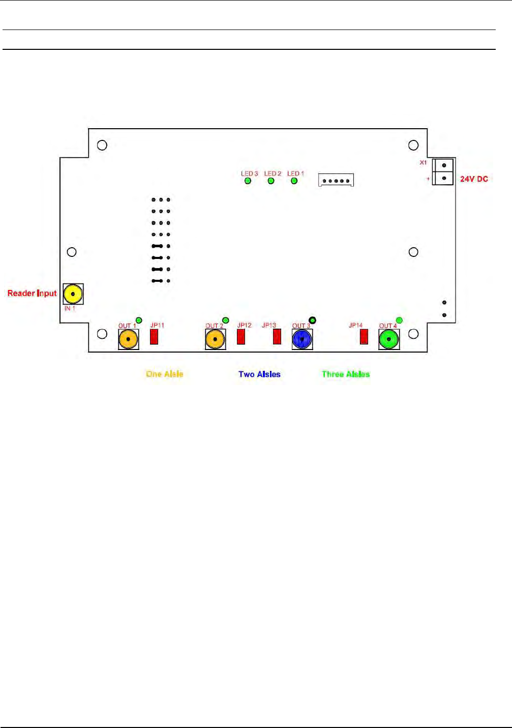
Fig. 18: Jumper positions
IDENTIFICATION Installation ID ISC.ANT1520/680-A/-B
FEIG ELECTRONIC GmbH Page 33 of 82 ID ISC.ANT1520680-A-B User
Manual_M61112-1e-ID-E-
060317.doc
6.3.4 Interface Connections
6.3.4.1 LAN / TCP/IP
The Reader has an integrated 10 / 100 Base-T network port for an RJ-45. Connection is made on
X1 and has an automatic “Crossover Detection” according to the 1000 Base-T Standard.
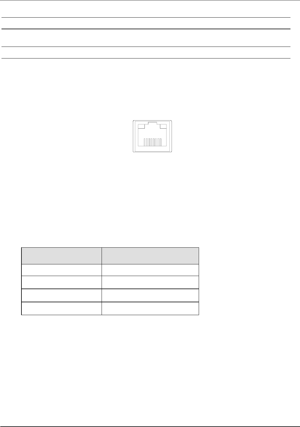
Fig. 19: LAN interface for host communication
With structured shielded cabling CAT-5 cables should be used. This ensures a reliable operation at
10 Mbps or 100 Mbps.
The prerequisite for using TCP/IP protocol is that each device has a unique address on the net-
work. All Readers have a factory set IP address.
Network Address
IP-Adresse 192.168.10.10
Subnet-Mask 255.255.255.0
Port 10001
DHCP OFF
Table 7 Standard factory configuration of the Ethernet connection
Note:
The Reader TCP/IP interface has a DHCP option.
More Information about the interfaces you will find in the manual M01111-xde-ID-B of the reader.
X1
IDENTIFICATION Installation ID ISC.ANT1520/680-A/-B
FEIG ELECTRONIC GmbH Page 34 of 82 ID ISC.ANT1520680-A-B User
Manual_M61112-1e-ID-E-
060317.doc
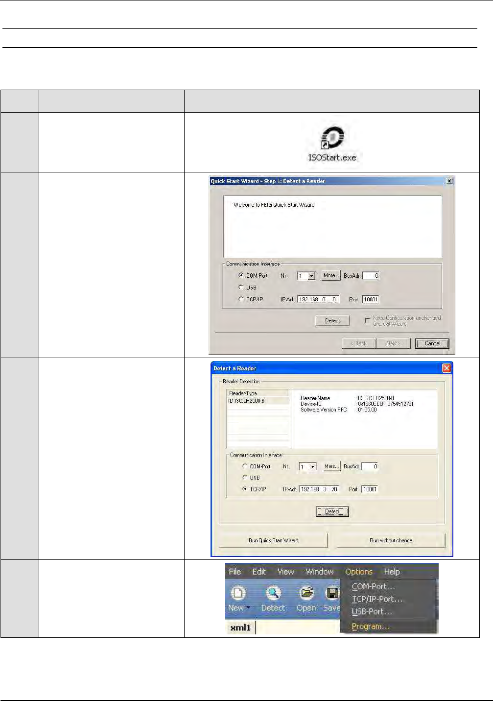
6.3.5 Reader Configuration with Multiplexer
To tune the antennas, open the ISOStart software and read out the current configuration of the
Reader:
Step
Action Note
1
Start ISO Start Software
2
Select „Detect“
3
Select „Run without change“
Note:
This has to be done at each
start of ISO-Start program
otherwise the configuration
of the reader will be changed
by the wizard.
4
Select „Options => Program“
IDENTIFICATION Installation ID ISC.ANT1520/680-A/-B
FEIG ELECTRONIC GmbH Page 35 of 82 ID ISC.ANT1520680-A-B User
Manual_M61112-1e-ID-E-
060317.doc
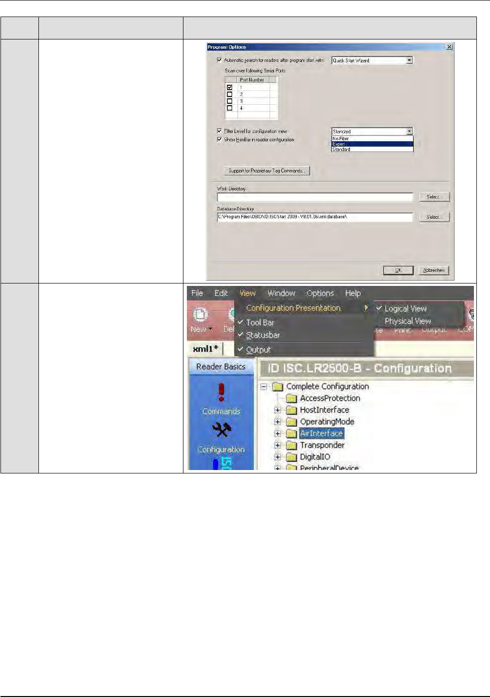
Step
Action Note
5
Select „Expert Mode“ and
confirm with OK.
6
Select “Logical View”
IDENTIFICATION Installation ID ISC.ANT1520/680-A/-B
FEIG ELECTRONIC GmbH Page 36 of 82 ID ISC.ANT1520680-A-B User
Manual_M61112-1e-ID-E-
060317.doc
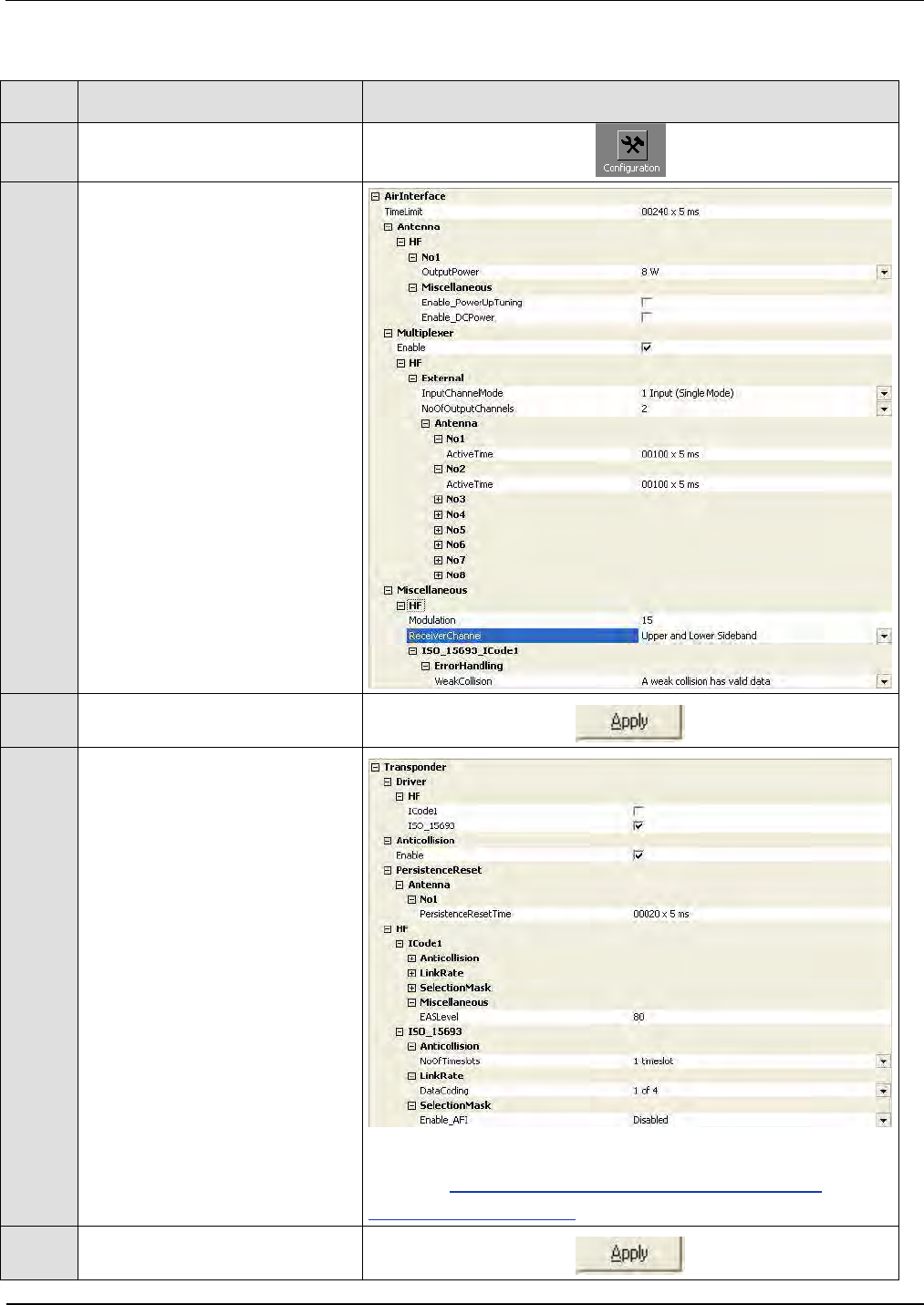
Afterwards set the operating power, Transponder Parameters and ISO Host Mode:
Step Action Note
1 Select “Configuration”
2
Air Interface:
“Output -Power” = 8W
„Multiplexer Enable“
„1 Input (Single Mode)“
„No of Output Channels „
(e.g. 2)
„Antenna Active Time“
100 x 5ms
“Receiver Channel” Upper
and Lower Sideband
3 Set by clicking on „Apply“.
4
Transponder:
Configure the parameters as
following:
• „Driver“ – here ISO 15693
• „Anticollision“ – enable
• „No of Timeslots“ –
1 timeslot
• „Data Coding“ – 1 of 4
• „AFI“ – Disabled
Note: National RF regulations may require different
settings. 8 Configure the reader in accordance with
national RF regulations
5 Set by clicking on „Apply“.
IDENTIFICATION Installation ID ISC.ANT1520/680-A/-B
FEIG ELECTRONIC GmbH Page 37 of 82 ID ISC.ANT1520680-A-B User
Manual_M61112-1e-ID-E-
060317.doc
Step Action Note
6
Operating Mode:
For antenna tuning the reader
has to be set to „Host Mode“.
7 Set by clicking on „Apply“.
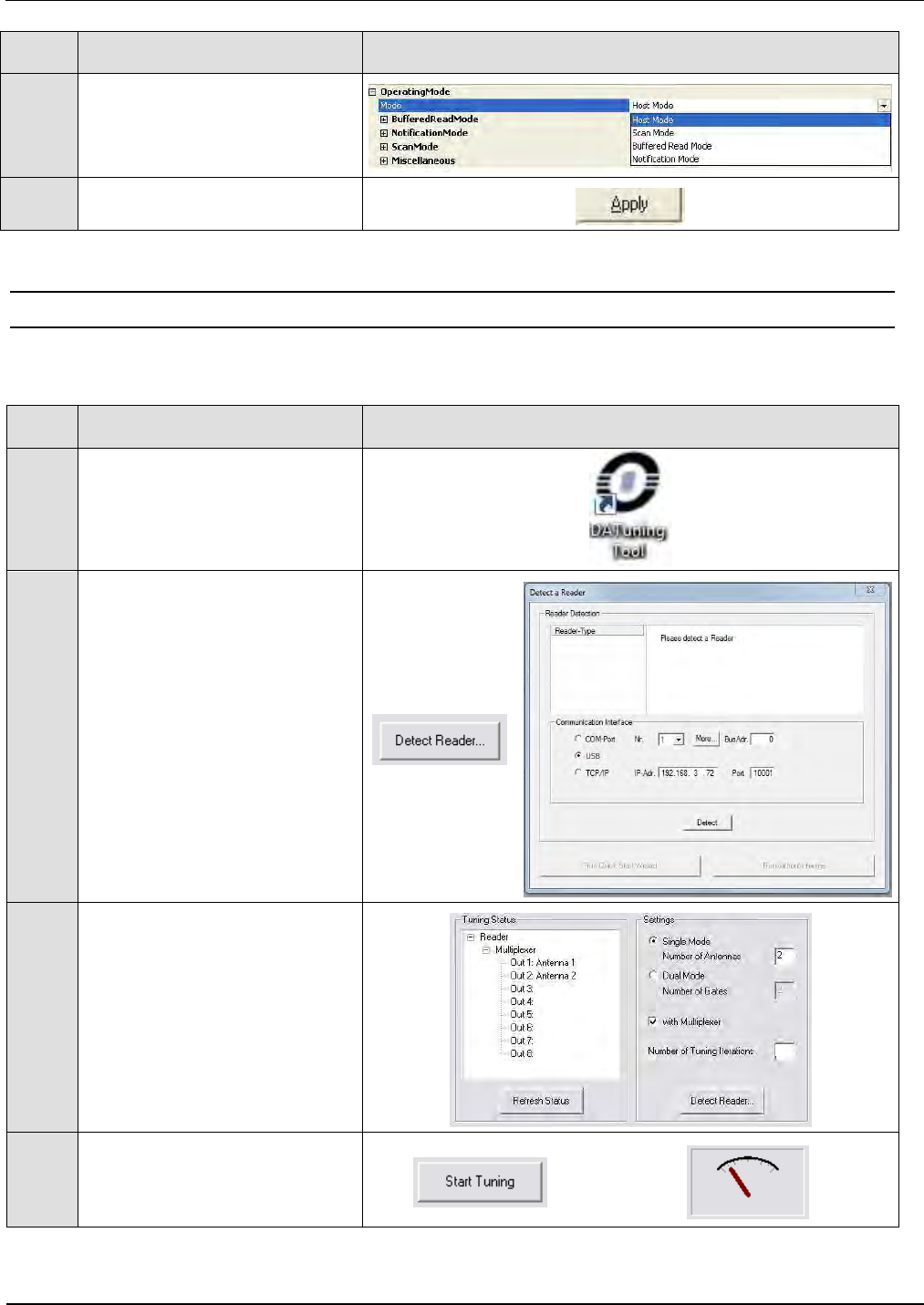
6.3.6 Tuning the Gate Antenna
Before tuning the gate antenna, you must quit the ISOStart software. Then the gate can be tuned
as follows:
Step
Action Note
1
Start “DATuningTool” software
2
Select “Detect Reader...”.
In the „Detect Reader“ window
select the interface (USB) and
then click on “Detect”.
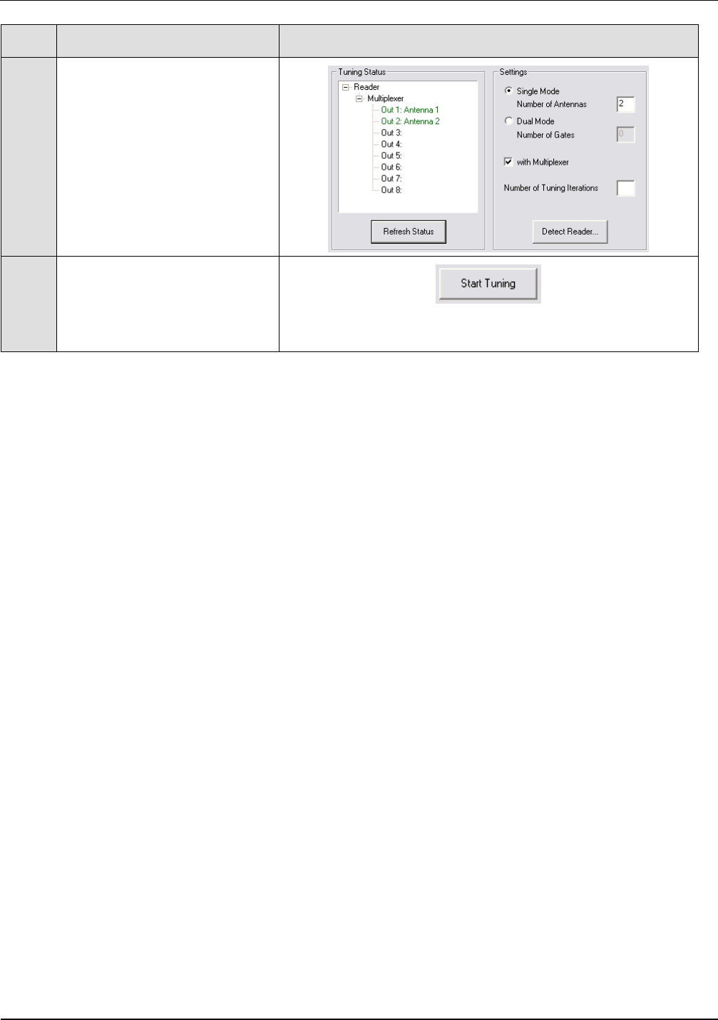
3
Use „Settings“ to enter the
configuration:
Single Mode,
Number of Antennas 2
Click on “with Multiplexer“
Number of Tuning Iterations 3
4
Activate „Start Tuning“ and
wait until the tuning process is
finished.
3
IDENTIFICATION Installation ID ISC.ANT1520/680-A/-B
FEIG ELECTRONIC GmbH Page 38 of 82 ID ISC.ANT1520680-A-B User
Manual_M61112-1e-ID-E-
060317.doc
Step
Action Note
5
The tuning status is displayed
after each tuning pass.
After successful tuning both
antennas are shown in green.
6
If this does not succeed on
the first try, start the process
again by clicking on „Start
Tuning“
After successful tuning, close the DATuningTool.
3
IDENTIFICATION Installation ID ISC.ANT1520/680-A/-B
FEIG ELECTRONIC GmbH Page 39 of 82 ID ISC.ANT1520680-A-B User
Manual_M61112-1e-ID-E-
060317.doc
6.4 Testing the Gate Antenna
After tuning the gate antenna, you can check for proper function using a reader, the ISOStart
service software and a Transponder. Here the Noise Level and performance of the gate are tested.
6.4.1 Checking the Noise Level
Step
Action Note
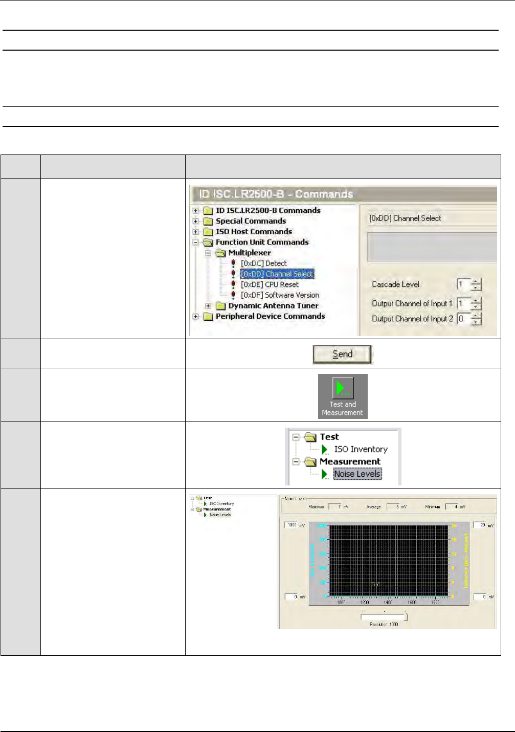
1
Activate antenna 1 with
command: „Function Unit
Commands - Multiplexer“
Parameter:
„Channel Select“
„Cascade Level = 1“
„Output Channel of Input 1
= 1“
2 Confirm with “Send”
3
Activate “Test and
Measurement”
4
Select „Noise Level“ and
start by clicking on „Start“
5
Normal Noise Level values:
Average:
< 30mV
Difference (Max-Min):
< 20mV
IDENTIFICATION Installation ID ISC.ANT1520/680-A/-B
FEIG ELECTRONIC GmbH Page 40 of 82 ID ISC.ANT1520680-A-B User
Manual_M61112-1e-ID-E-
060317.doc
Step
Action Note
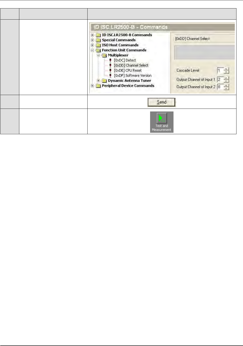
6
Activate antenna 2 with
command: „Function Unit
Commands - Multiplexer“
Parameter:
„Channel Select“
„Cascade Level = 1“
„Output Channel of Input 1
= 2“
7 Confirm with “Send”
8
Repeat Step 3 to 5 for
every further antenna
If the values are not proper, check the following:
• Are all cables pulled tight and will contact well?
• Are the ferrite installed in the antenna cable?
• Are the cables routed as specified?
• Are other RFID systems installed closed by?
• Are there large metal parts close to the antenna (distance < 1.0 m)?
• Are there devices nearby which may emit noise interferences (larger machines or wireless
devices)?
• Are there interferences from the mains?
To determine which devices may be disturbing the gate, briefly disconnect them from the mains.
IDENTIFICATION Installation ID ISC.ANT1520/680-A/-B
FEIG ELECTRONIC GmbH Page 41 of 82 ID ISC.ANT1520680-A-B User
Manual_M61112-1e-ID-E-
060317.doc
6.4.2 Reading a Serial Number
Step
Action Note
1
Attach a tag to an antenna
Here to antenna at multi-
plexer output 1
Use adhesive tape, for example
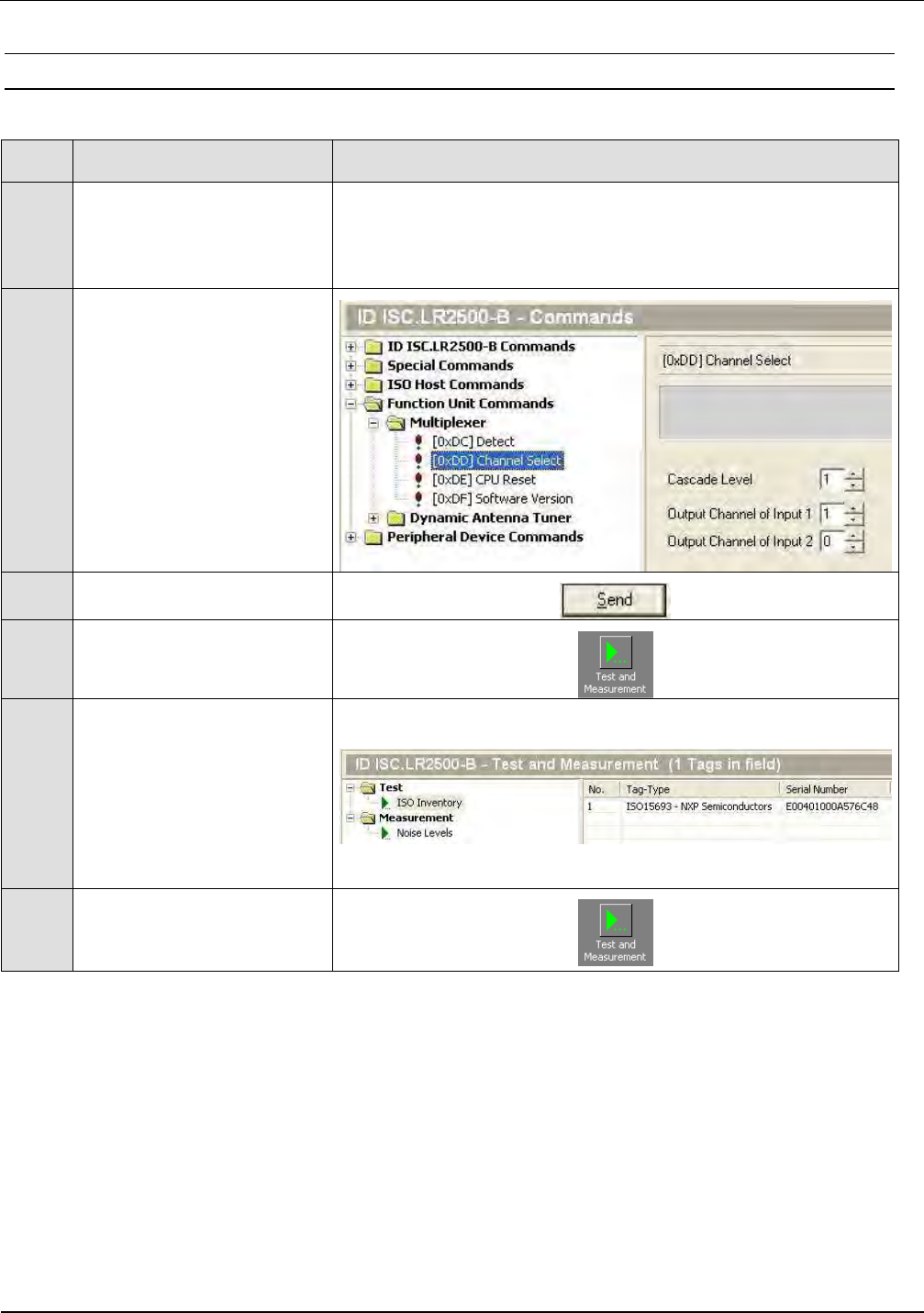
2
Activate antenna 1 with
command: „Function Unit
Commands - Multiplexer“
Parameter:
„Channel Select“
„Cascade Level = 1“
„Output Channel of Input 1
= 1“
3 Confirm with “Send”
4 Select „Test and
Measurement“
5
Select „ISO Inventory“
function and activate by
clicking on „Start“.
The serial number and tag
type will be shown in the
display.
6 Repeat Step 1 to 5 for
every further antenna
IDENTIFICATION Installation ID ISC.ANT1520/680-A/-B
FEIG ELECTRONIC GmbH Page 42 of 82 ID ISC.ANT1520680-A-B User
Manual_M61112-1e-ID-E-
060317.doc
6.4.3 Testing the performance
For testing the performance you must switch the reader to one of the Automatic Modes.
A read transponder will be displayed by a blue LED on the reader, the Alarm LED light of the
antenna and the Alarm buzzer. See also 6.5.3 Reader Setting for Alarm Indicator
In this test the capture area of the gate antenna described in 6.1 Project Notes is checked. For
other tags or other configurations the indicated ranges and read areas may differ accordingly.
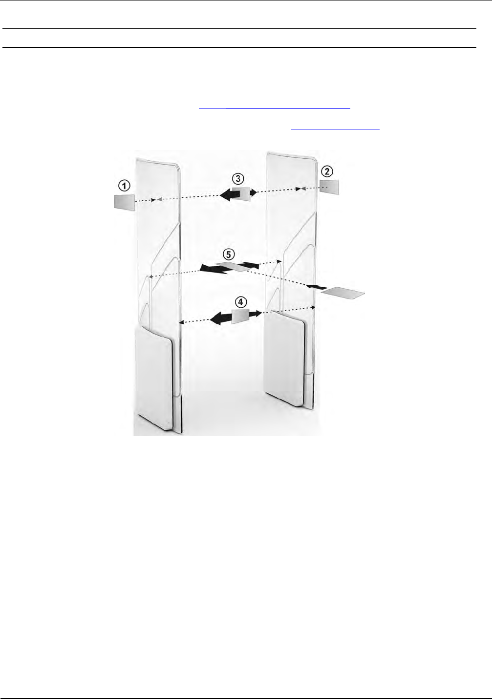
Fig. 20: Performance Test of the gate antenna
The test begins by checking the read range outside the gate (see Fig. points
and
), assuming
the configuration and locality permit it. If the tag is oriented parallel to the antenna at the outside, a
read range of 65 to 70 cm should be achieved.
The three tag orientations are checked inside the gate. This corresponds to the lines and
orientations
. Now slowly move the tag in the vertical and parallel direction with respect to
the antenna along the line
from one side to the other. The tag should always be read.
Then repeat this along the line
in the vertical tag direction transverse to the antenna and on the
line
in the horizontal tag orientation. Here again the tag should always be read.
The tag should be read within the gate by moving in a horizontal line through the gate in all
three read orientations.

IDENTIFICATION Installation ID ISC.ANT1520/680-A/-B
FEIG ELECTRONIC GmbH Page 43 of 82 ID ISC.ANT1520680-A-B User
Manual_M61112-1e-ID-E-
060317.doc
If one or more „holes“ are detected, check the noise values on the Reader (see 6.4.1 Checking the
Noise Level).
The following may result in faulty readings:
• Antenna improperly installed (orientation, antenna distance, check cabling)
• Metal near the antennas is detuning or interfering with them.
• The antennas are not properly tuned.
• Noise level too high (Vmax – Vmin ≥ 20 mV)
• Transponder too insensitive, detuned or defective
• Reader improperly configured (transmitting power, transponder type, modulation, transponder
parameters, etc.).
• A cable is defect or has a weak contact.
• Reader, multiplexer or antenna defect.
IDENTIFICATION Installation ID ISC.ANT1520/680-A/-B
FEIG ELECTRONIC GmbH Page 44 of 82 ID ISC.ANT1520680-A-B User
Manual_M61112-1e-ID-E-
060317.doc
6.5 Setting the Alarm indicators (Alarm Buzzer and Alarm LED´s)
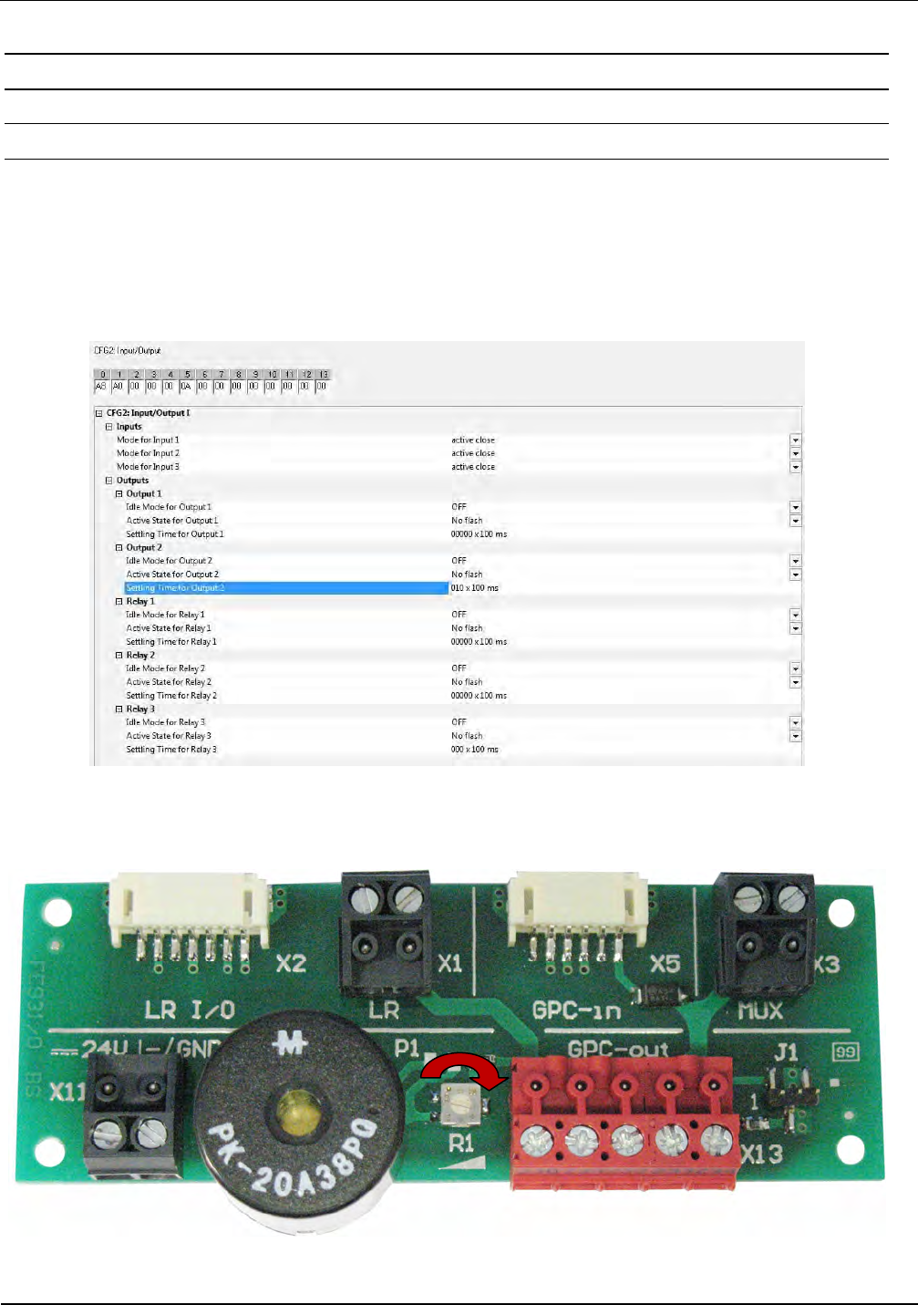
6.5.1 Setting the Buzzer
The solution provided here presumes that the alarm indicator (buzzer) is switched through the
digital output 2 /X2 on the ID ISC.LRM2500-B reader. The pulse duration can be set (CFG2 /
OUT2) between 100 ms and 65535 s by adjusting the Reader configuration. The volume of the
buzzer could be adjusted by R1
Fig. 21 Configuration Buzzer
Fig. 22 Volume adjusting
IDENTIFICATION Installation ID ISC.ANT1520/680-A/-B
FEIG ELECTRONIC GmbH Page 45 of 82 ID ISC.ANT1520680-A-B User
Manual_M61112-1e-ID-E-
060317.doc
6.5.2 Setting the LED´s
The alarm LED´s will be switched by a command of the reader over the RS485 Bus.
Due to that reason the terminal boards of all used antennas have to be connected 1:1 in parallel
together.
The Bus address for each LED will be defined by the antenna number it is installed in.
The antenna number depends on the output of the Multiplexer the antenna is connected to.
The Bus address will be set automatically after setup and configuration of the complete gate sys-
tem after a “System Reset” command in one of the Automatic Modes.
The successful detection of the connected LED´s could be checked
with the command “Get Reader Info”
The number of detected LED´s and it´s firmware version will be also displayed in the LCD Display
after a power up or the command “System Reset”.
LED in Antenna
No.
Connected to Multiplexer
Output No.
Bus Address No.
1 1 11
2 2 12
3 3 13
4 4 14
5 5 15
6 6 16
7 7 17
Table 8
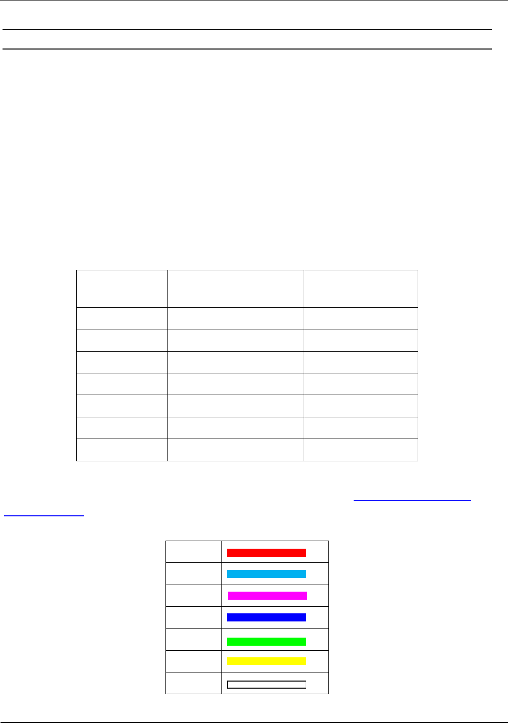
The color of the LED could configured with the ISO-Start software. see 6.5.3 Reader Setting for
Alarm Indicators
The following colors could be set:
Red
Cyan
Magenta
Blue
Green
Yellow
White
Table 9
IDENTIFICATION Installation ID ISC.ANT1520/680-A/-B
FEIG ELECTRONIC GmbH Page 46 of 82 ID ISC.ANT1520680-A-B User
Manual_M61112-1e-ID-E-
060317.doc
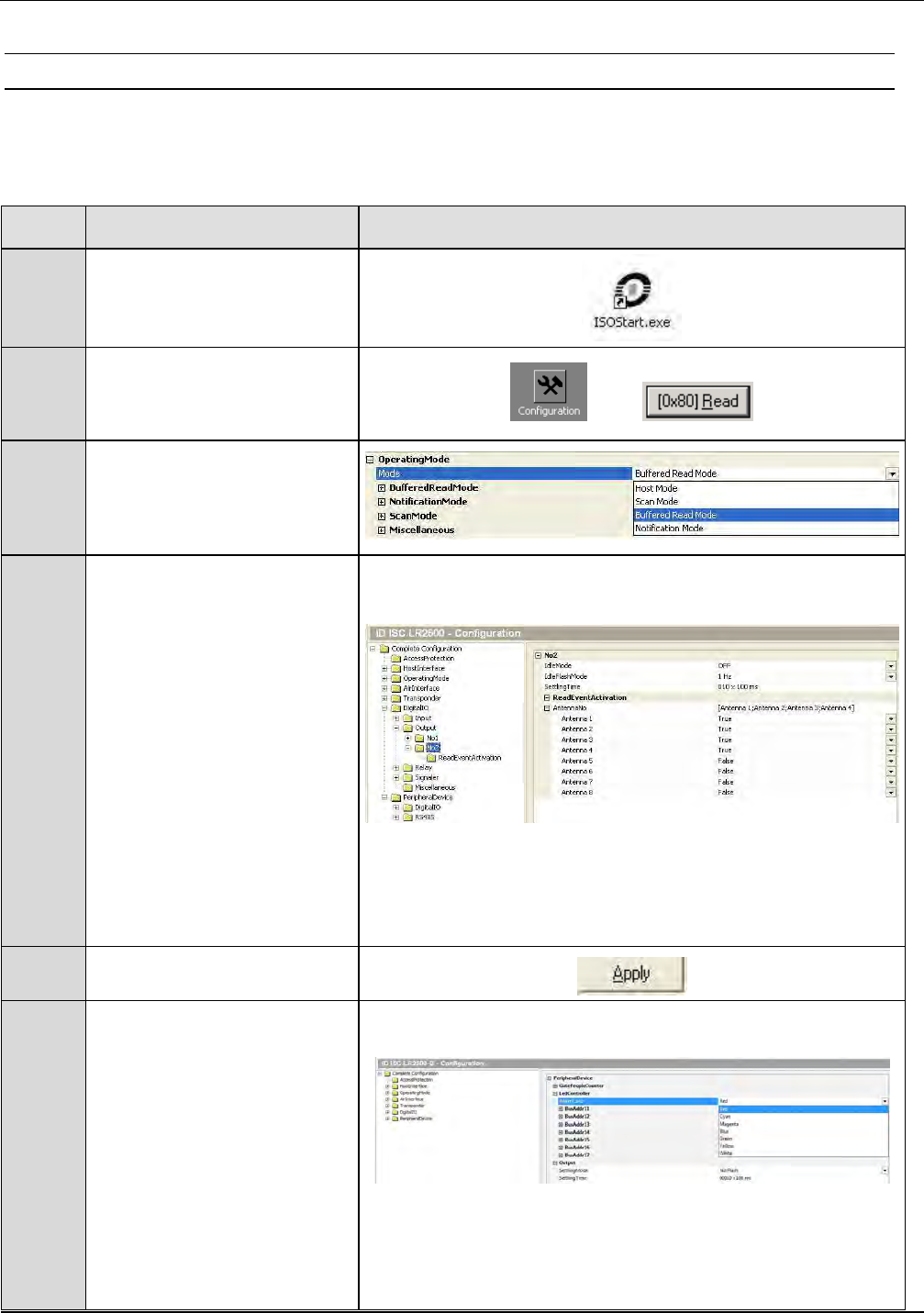
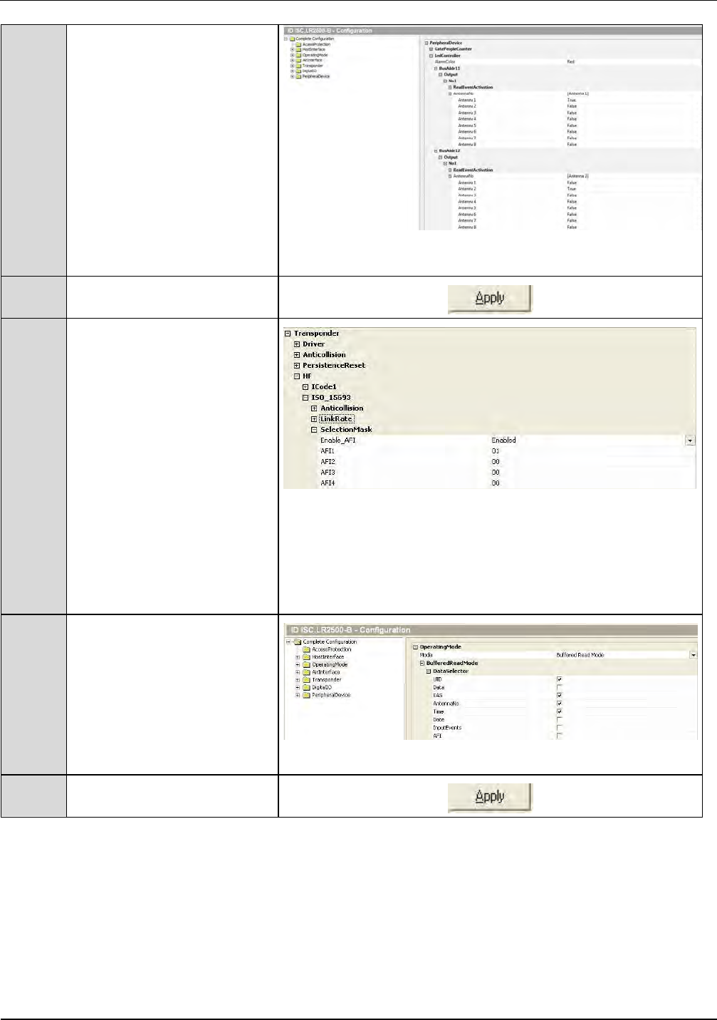
6.5.3 Reader Setting for Alarm Indicators
The ISOStart software can be used to set the Reader configuration so that the output 2 X6-1/-2
opens or closes or the LED´s get a command when a Transponder is read.
Step Action Note
1 Start ISOStart Software
2 Select “Configuration” and
click on “Read” to read the
complete configuration.
3 Operating Mode
Select Buffered Read Mode.
4
Digital IO:
Output Idle Mode: OFF
Idle Flash Mode: 1Hz
Setting Time:
with „Setting Time“ set
time of output 2 for alarm
duration.
(10 means 1 second)
(e.g. 10 x 100ms)
Assign Output 2 to antenna
1+2. „True“ means: Output 2
will be active if the reader
reads a valid transponder.
5 Set by clicking on „Apply“.
6
Peripheral Device
LED Controller:
Setting Time:
„Setting Time“ set the dura-
tion time for the alarm.
(10 means 1 second)
(e.g. 10 x 100ms)
Set the colour for the LED´s
IDENTIFICATION Installation ID ISC.ANT1520/680-A/-B
FEIG ELECTRONIC GmbH Page 47 of 82 ID ISC.ANT1520680-A-B User
Manual_M61112-1e-ID-E-
060317.doc
Assign
LED Bus Address 11 to
antenna 1.
LED Bus Address 12 to
antenna 2.
......... and so on.
„True“ means: LED with Bus
Address 11, 12, ... 17 will be
active if the reader read a
valid transponder on the
corresponding antenna
7 Set by clicking on „Apply“
8
Transponder
If the alarm should occur by
a transponder with valid AFI
byte, you have to configure
the reader as follow:
ISO-15693 – Selection Mask
Set “Enable AFI”
Set the value for the AFI in
field “AFI1” (e.g. 01)
Note:
Up to four different AFI
values could be set.
9
Operating Mode
If the alarm should occur by
an EAS, you have to
configure the reader as
follow:
Set “EAS”
10 Set by clicking on „Apply“
IDENTIFICATION Installation ID ISC.ANT1520/680-A/-B
FEIG ELECTRONIC GmbH Page 48 of 82 ID ISC.ANT1520680-A-B User
Manual_M61112-1e-ID-E-
060317.doc
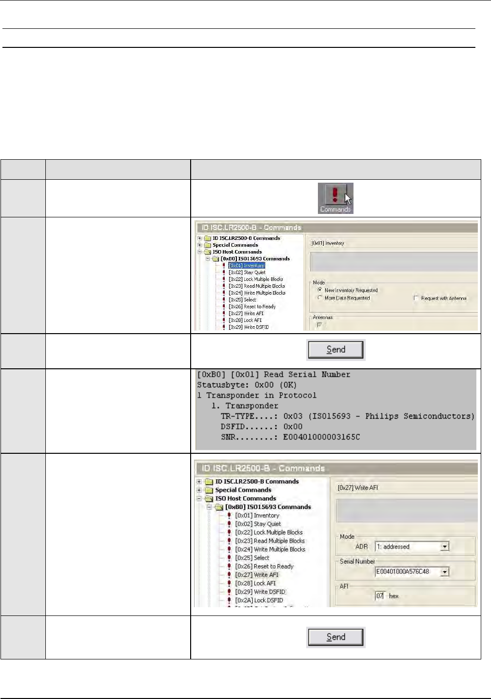
6.5.4 Programming a Transponder with the AFI Byte
If the Transponders will remain on the object when leaving the storage location, they must first be
disabled. This is generally done by writing to a particular area of the Transponder.
The AFI byte (Application Family Identifier) is useful for this purpose, since it is contained in nearly
all Transponder models in the ISO15693 family. To disable, simply write a different code to the
Transponder than for valid Transponders which trigger an alarm.
Step Action: Note:
1 Select „Commands“
2
Place the Transponder in the
antenna field (Antenna 1)
Select [0x01] Inventory
Mode: “New Inventory
Requested “
3 Read UID by clicking on
„Send“
4
The serial number, DSFID
and Transponder type are
displayed in a window.
Write down the serial number
of the Transponder
5
Select „[0x27] Write AFI“
ADR:
1: addressed
Serial Number:
Select Transponder UID
AFI:
Desired AFI Number (not
equal to 00)
6 Write AFI byte on to the
transponder by click on
„Send“

IDENTIFICATION Installation ID ISC.ANT1520/680-A/-B
FEIG ELECTRONIC GmbH Page 49 of 82 ID ISC.ANT1520680-A-B User
Manual_M61112-1e-ID-E-
060317.doc
7
To verify, read AFI byte by
using the command
[0x2B] Get System
Information
IDENTIFICATION Installation ID ISC.ANT1520/680-A/-B
FEIG ELECTRONIC GmbH Page 50 of 82 ID ISC.ANT1520680-A-B User
Manual_M61112-1e-ID-E-
060317.doc
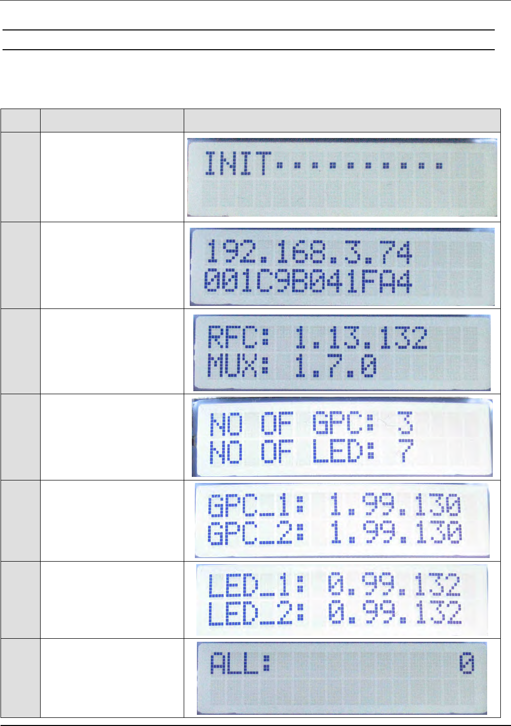
6.6 Functions of the LCD-Display
Only in the Automatic Modes (Scan, Notification or Buffered read Mode) the Display will work as
described. After power up the antenna type A or the command “System Reset” the Display will
show:
Step
Description Display
1
Means reader is not in one
of the Automatic modes
after power up..
Please set reader to one of
the Automatic Modes.
2
Reader
IP address
and
MAC address
3
RFC Firmware Version of
Reader
Firmware Version of
Multiplexer
4
Number of connected and
detected
Gate People Counter and
LED-Controller
5
Firmware Version of each
detected GPC
6
Firmware Version of each
detected LED-Controller
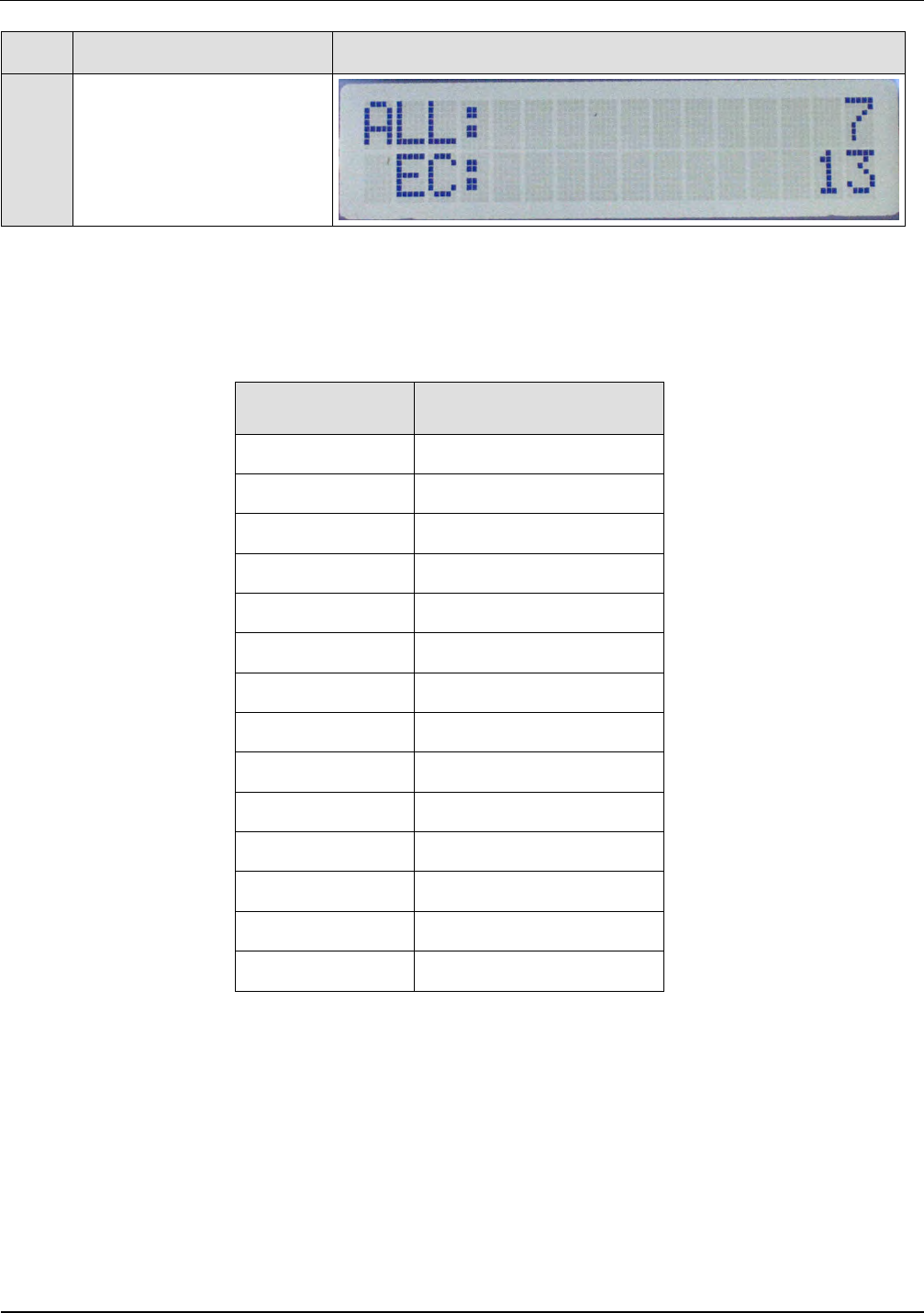
7
The sum of the all counted
people on all GPC
(IN+OUT) till now.
IDENTIFICATION Installation ID ISC.ANT1520/680-A/-B
FEIG ELECTRONIC GmbH Page 51 of 82 ID ISC.ANT1520680-A-B User
Manual_M61112-1e-ID-E-
060317.doc
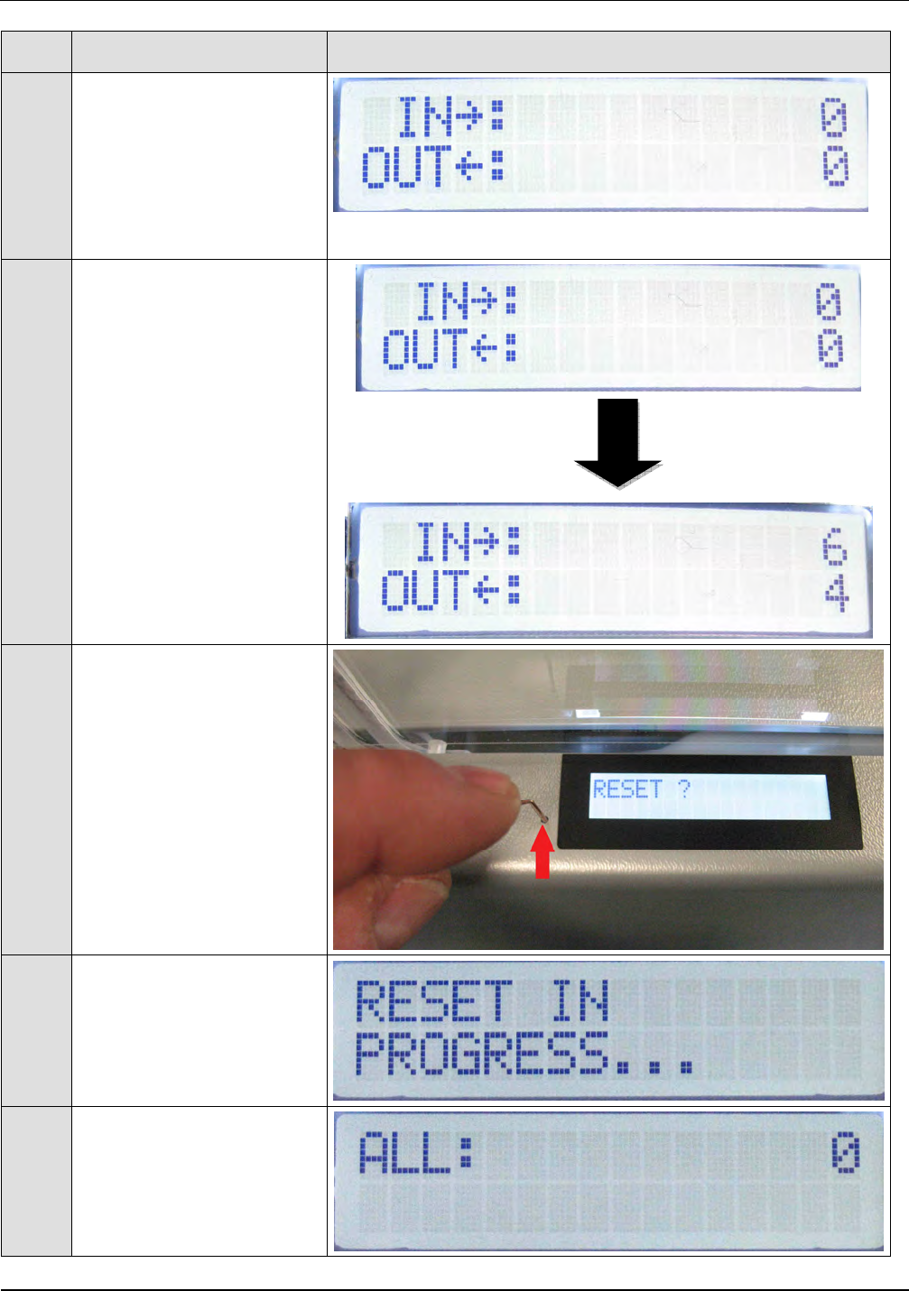
Step
Description Display
8
Then the counter values for
IN and OUT of all
connected GPC.
After that the display will
change between ALL and
IN /OUT values
9
The Counter values in the
display will be updated
every 5 seconds !
5 seconds
10
The counter values could
be Reset with a paper clip
by pressing the Reset
Button under the hole
beside the Display.
The counter values of all
connected GPC will be set
to 0.
11
Press the Reset Button till
the Reset process starts.
The Reset process could
take up to 30 seconds.
12
After the Reset process the
display will start again to
show the values.
IDENTIFICATION Installation ID ISC.ANT1520/680-A/-B
FEIG ELECTRONIC GmbH Page 52 of 82 ID ISC.ANT1520680-A-B User
Manual_M61112-1e-ID-E-
060317.doc
Step
Description Display
13
If an error occurs the
Error Code will be shown
together with the ALL
values.
The meaning of the Error Code will be shown in table 10 below.
Error Code Error Flag
10 RF-HW
12 |Z| <
13 |Z| >
14 CONTROL
15 TEMP_WARN
16 SYNC
17 TEMP-ALARM
18 MUX
19 DAT
40 EE_DEV1
41 EE_DEV2
43 RF-Decoder
45 People_Counter
4C LED
Table 10
If more than one error occurs, the error code with the lowest number will be displayed.
IDENTIFICATION Installation ID ISC.ANT1520/680-A/-B
FEIG ELECTRONIC GmbH Page 53 of 82 ID ISC.ANT1520680-A-B User
Manual_M61112-1e-ID-E-
060317.doc
6.7 Activating the Automatic Mode
The gate has to be used in one of the Automatic Modes (Buffered Read, Notification
or Scan Mode) to get a maximum performance. Otherwise the reading performance
will be significantly reduced.
For more information, see System Manual H01112-0e-ID-B.pdf ID ISC.LRM2500-A/B
Which mode the most suitable is for your application has to be defined in advance.
In this example it is described how to activate the Buffered Read Mode.
In the automatic modes, the tags are read at maximum speed and the information is stored in the
ring buffer of the reader. Data set can be read by the host.
Due to the automatic alarm features at the automatic mode, the reader/gate can also run without
any interface connection (Serial, Ethernet).
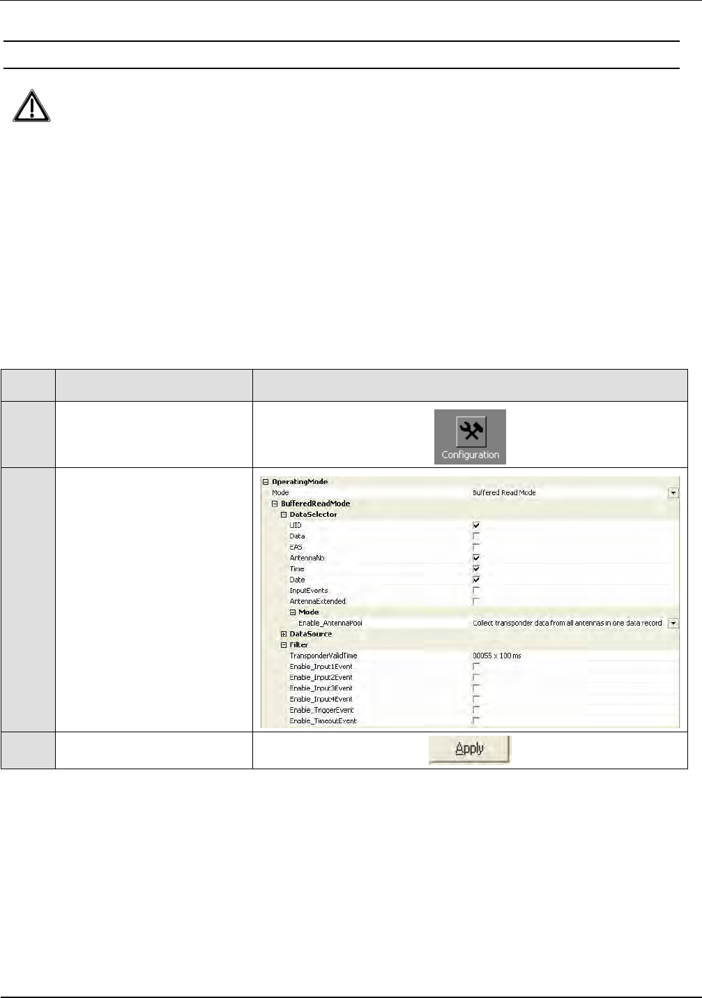
To activate „Buffered Read Mode“ proceed as follows:
Step
Action Note
1 Select „Configuration“
2
Operation Mode:
„Mode“ - Buffered Read
Mode
„Data Selector“
-UID
-Antenna No
-Time
-Date
„Filter“
Set Transponder Valid
Time.
(e.g. 55 x 100ms)
3 Set clicking on „Apply“
Note:
The configuration of the Notification or Scan Mode are similar (See System Manual of the reader)
To test the function of the Gate in the Buffered Read Mode, the BRM Window of ISOStart can be
used.
IDENTIFICATION Installation ID ISC.ANT1520/680-A/-B
FEIG ELECTRONIC GmbH Page 54 of 82 ID ISC.ANT1520680-A-B User
Manual_M61112-1e-ID-E-
060317.doc
6.8 Installation ID ISC.ANT.GPC-E2
Content of the ID ISC.ANT.GPC-E2 1. 1 piece Radar connection cable
2. 1 piece Radar module
3. 2 piece spilt rivet 3,0mm
4. 1 piece cable-clip
Step
Action Note
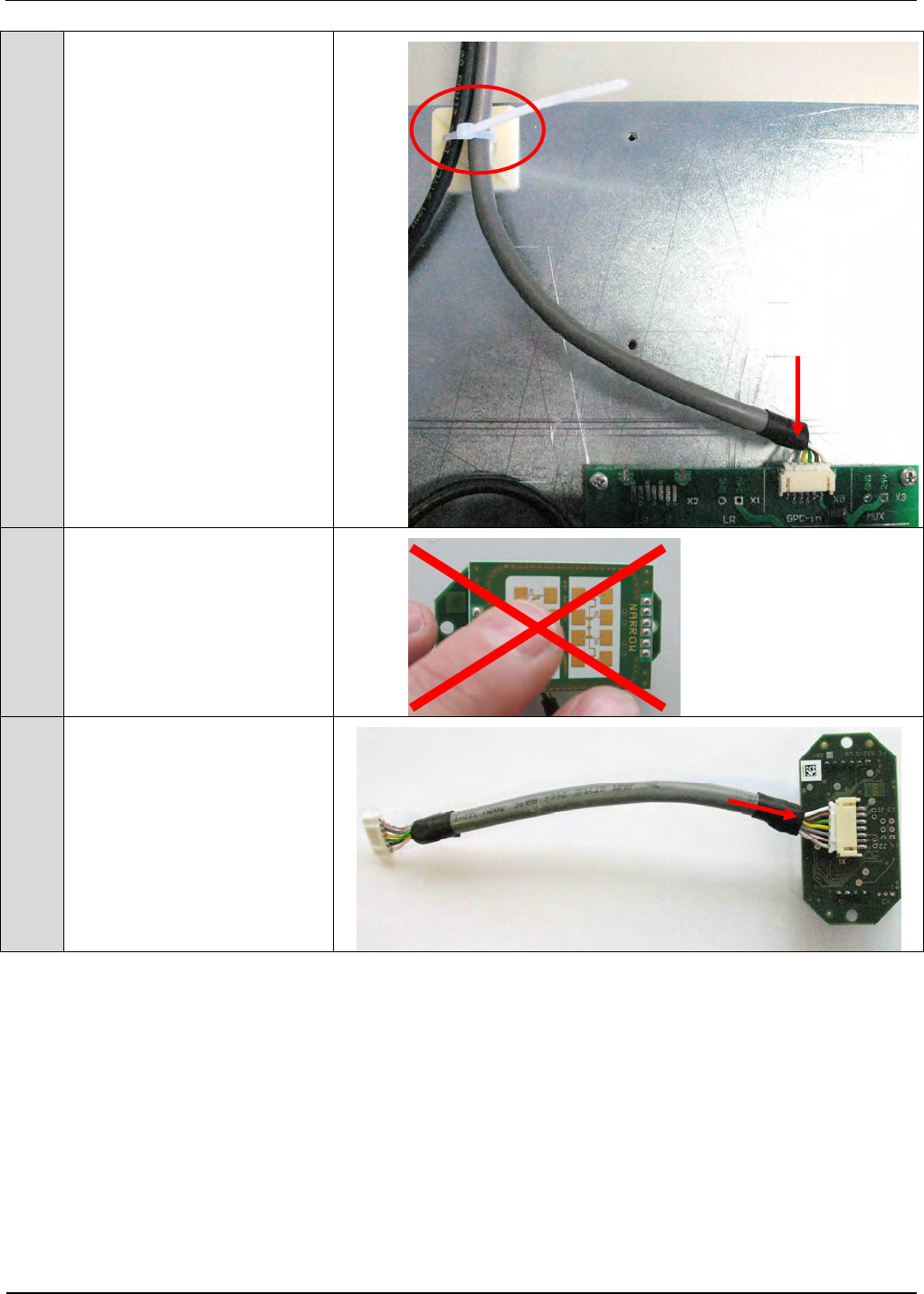
1.
Attention !!
Note: Do not touch the an-
tenna surface of the Radar
module to avoid damaging
the electronic components
and soiling.
2.
Connect radar connection
cable with X1 of Radar
module.
4. 3.
3.
2.
1.
IDENTIFICATION Installation ID ISC.ANT1520/680-A/-B
FEIG ELECTRONIC GmbH Page 55 of 82 ID ISC.ANT1520680-A-B User
Manual_M61112-1e-ID-E-
060317.doc
3.
Plug Radar connection
cable into X12 Sen 2 and
fix the cable with the cable
clip.
4.
Install Radar module with
the two split rivets
See picture
5.
The sensitivity of the radar
module will be set auto-
matically by the GPC after
power up the gate system.
To check/set the sensitivity see also 7.2.2 Configuration and
Test in ISO-Host or Buffered Read Mode, Step 8
Fig. 23: Connections GPC-2E 2.Radarmodule
ID ISC.ANT.GPC-E2
ID ISC.ANT.GPC
1.Radarmodule
X11 X12
IDENTIFICATION Installation ID ISC.ANT1520/680-A/-B
FEIG ELECTRONIC GmbH Page 56 of 82 ID ISC.ANT1520680-A-B User
Manual_M61112-1e-ID-E-
060317.doc
7 Installation of the Gate People Counter ID ISC.ANT.GPC in antenna Type B
7.1 Installation and Connections
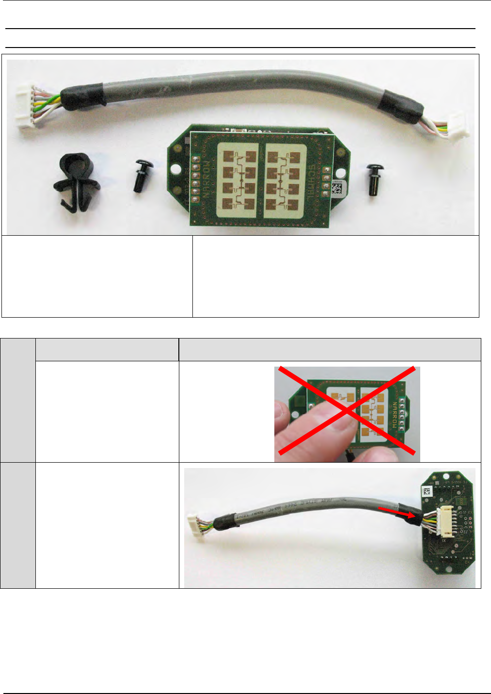
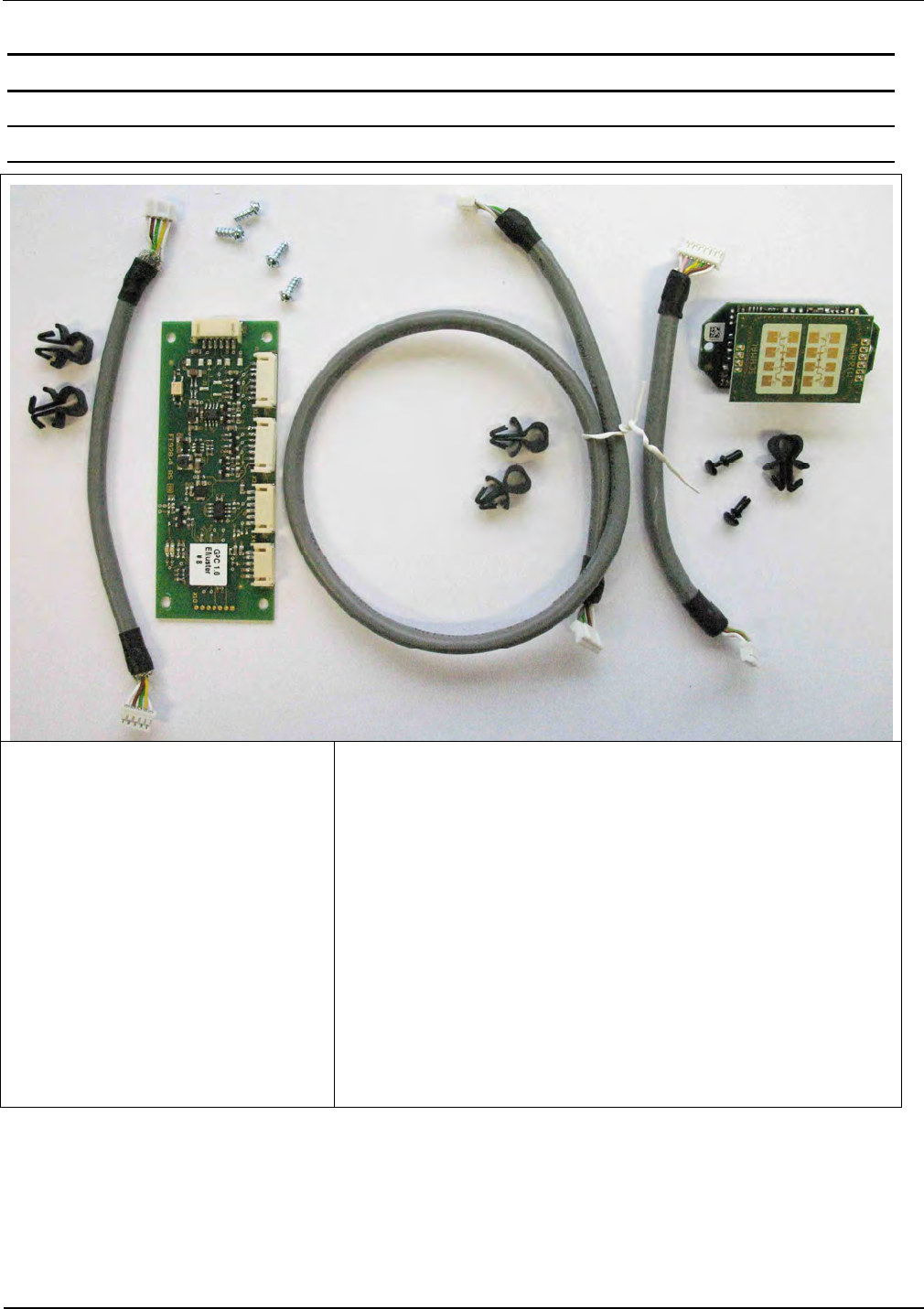
Contents of the
ID ISC.ANT.GPC
1. 1 piece connection cable People Counter –Terminal
board
2. 1 piece Radar connection cable
3. 1 piece LED connection cable
4. 1 piece People Counter Board
5. 1 piece Radar module
6. 1 piece cable tie
7. 4 piece screw for plastic 3x12mm
8. 5 piece cable-clip
9. 2 piece split rivet 3,0mm
10. 1 piece FCC / IC Label
2.
1.
3.
4.
5.
6.
7.
8.
9.
12.
12.
8.
8.
IDENTIFICATION Installation ID ISC.ANT1520/680-A/-B
FEIG ELECTRONIC GmbH Page 57 of 82 ID ISC.ANT1520680-A-B User
Manual_M61112-1e-ID-E-
060317.doc
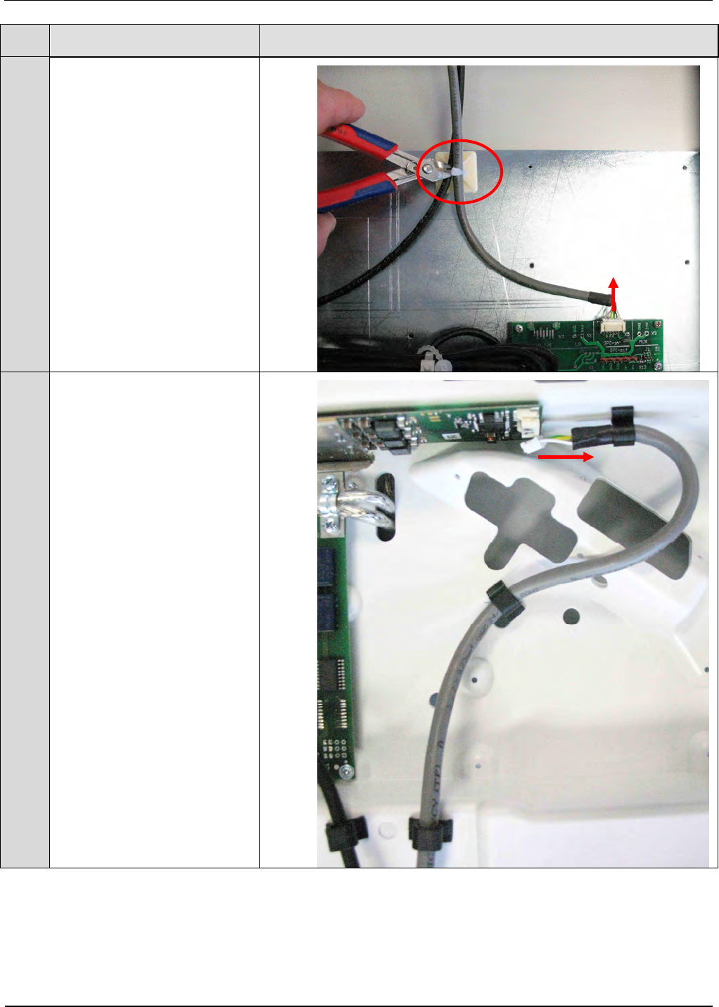
Step
Action Note
1.
Disconnect LED connection
cable at the terminal board
and cut the cable tie in the
antenna foot.
2. Disconnect LED connection
cable at LED controller.
IDENTIFICATION Installation ID ISC.ANT1520/680-A/-B
FEIG ELECTRONIC GmbH Page 58 of 82 ID ISC.ANT1520680-A-B User
Manual_M61112-1e-ID-E-
060317.doc
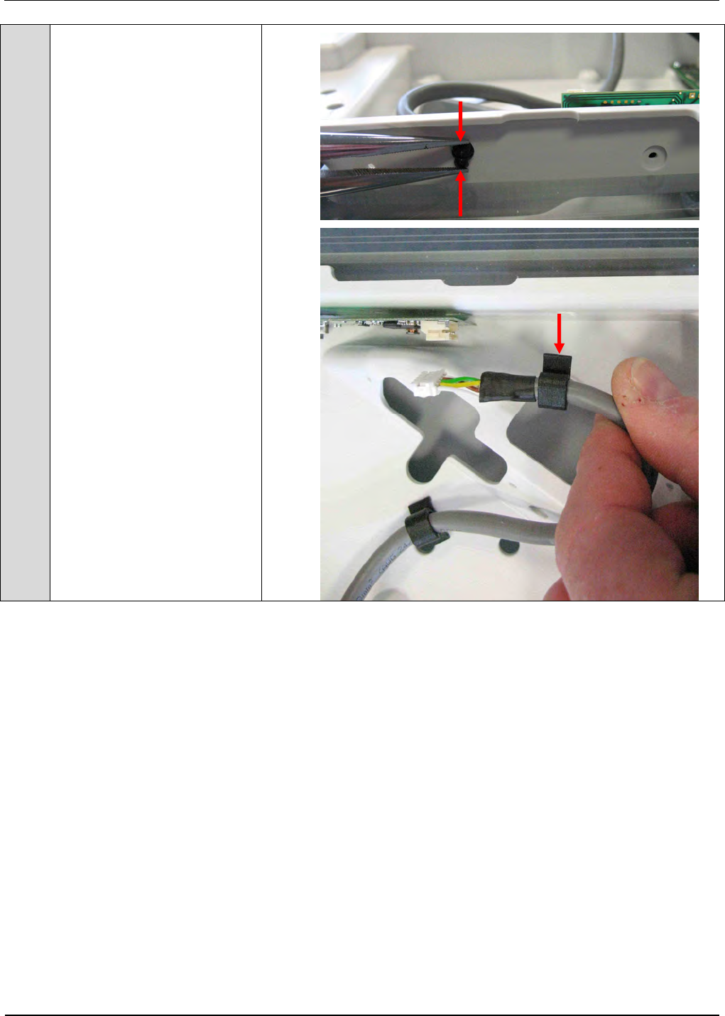
3. Remove the cable clip be-
side the LED controller.
IDENTIFICATION Installation ID ISC.ANT1520/680-A/-B
FEIG ELECTRONIC GmbH Page 59 of 82 ID ISC.ANT1520680-A-B User
Manual_M61112-1e-ID-E-
060317.doc
4. Remove the 2 other cable
clips by pulling them out
with the cable.
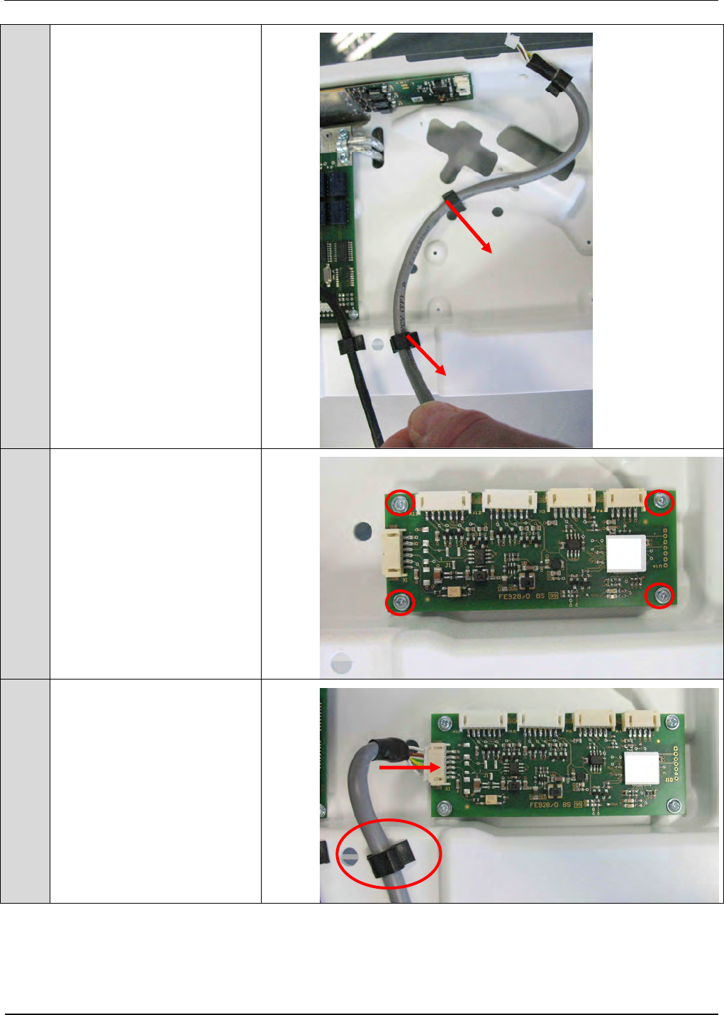
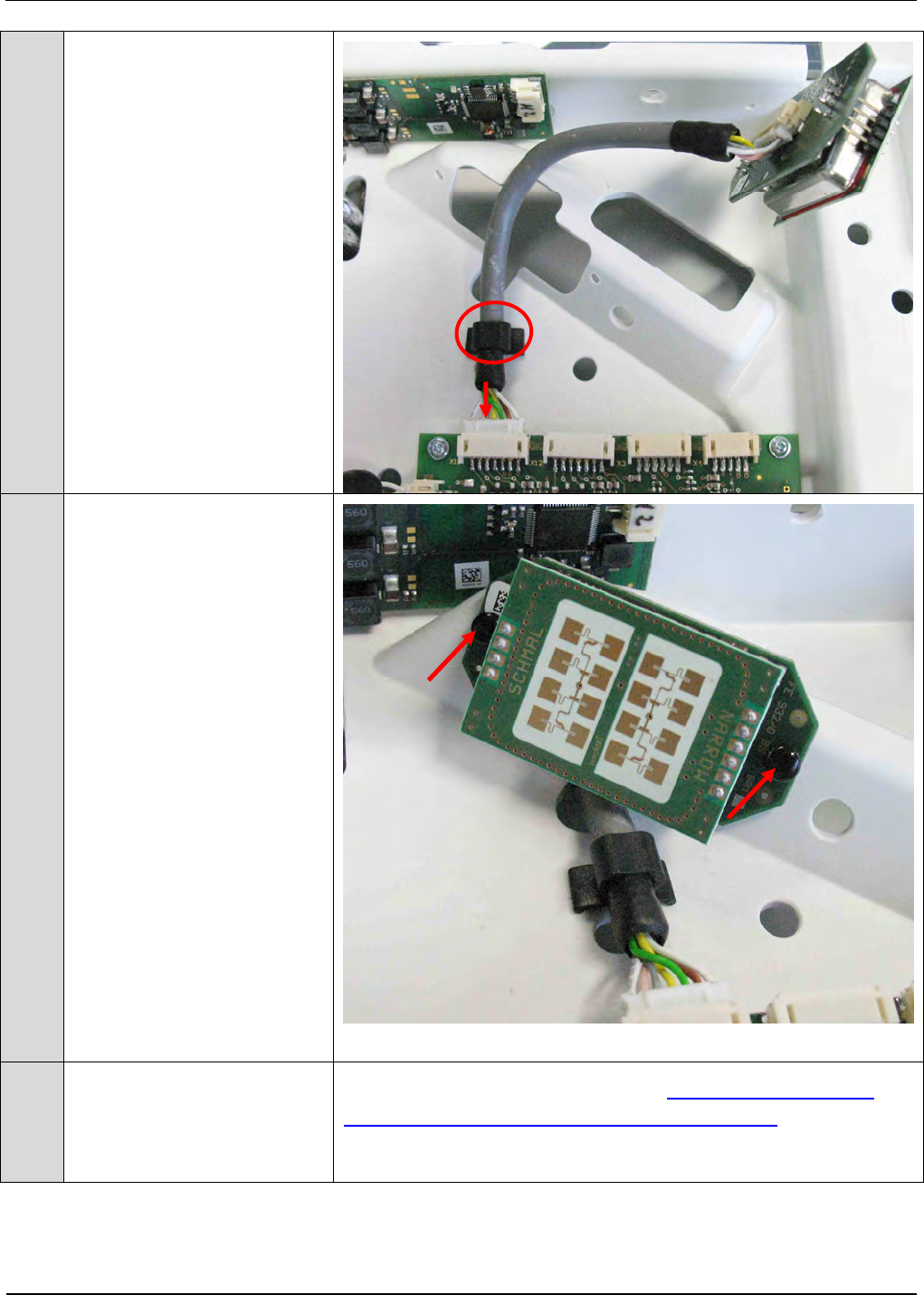
5. Install People Counter
Board into antenna with
screws for plastic
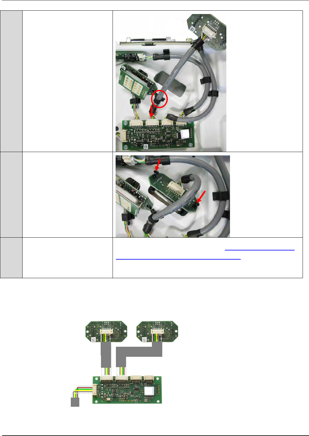
6. Plug GPC connection cable
onto X1 at GPC and X5
GPC-in at terminal board
and fix it with two cable
clips and the cable tie.
IDENTIFICATION Installation ID ISC.ANT1520/680-A/-B
FEIG ELECTRONIC GmbH Page 60 of 82 ID ISC.ANT1520680-A-B User
Manual_M61112-1e-ID-E-
060317.doc
7. Attention !!
Note: Do not touch the an-
tenna surface of the Radar
module to avoid damaging
the electronic components
and soiling.
8. Connect radar connection
cable with X1 of Radar
module.
IDENTIFICATION Installation ID ISC.ANT1520/680-A/-B
FEIG ELECTRONIC GmbH Page 61 of 82 ID ISC.ANT1520680-A-B User
Manual_M61112-1e-ID-E-
060317.doc
9. Plug Radar connection
cable onto X11 Sen 1 at
GPC and fix the cable with
the cable clip.
10.
Install Radar module with
split rivet.
Use installation hole that
radar module surface faces
between the antennas.
11.
The sensitivity of the radar
module will be set auto-
matically by the GPC after
power up the gate system.
To check/set the sensitivity see also 7.2.2 Configuration and
Test in ISO-Host or Buffered Read Mode, Step 8
IDENTIFICATION Installation ID ISC.ANT1520/680-A/-B
FEIG ELECTRONIC GmbH Page 62 of 82 ID ISC.ANT1520680-A-B User
Manual_M61112-1e-ID-E-
060317.doc
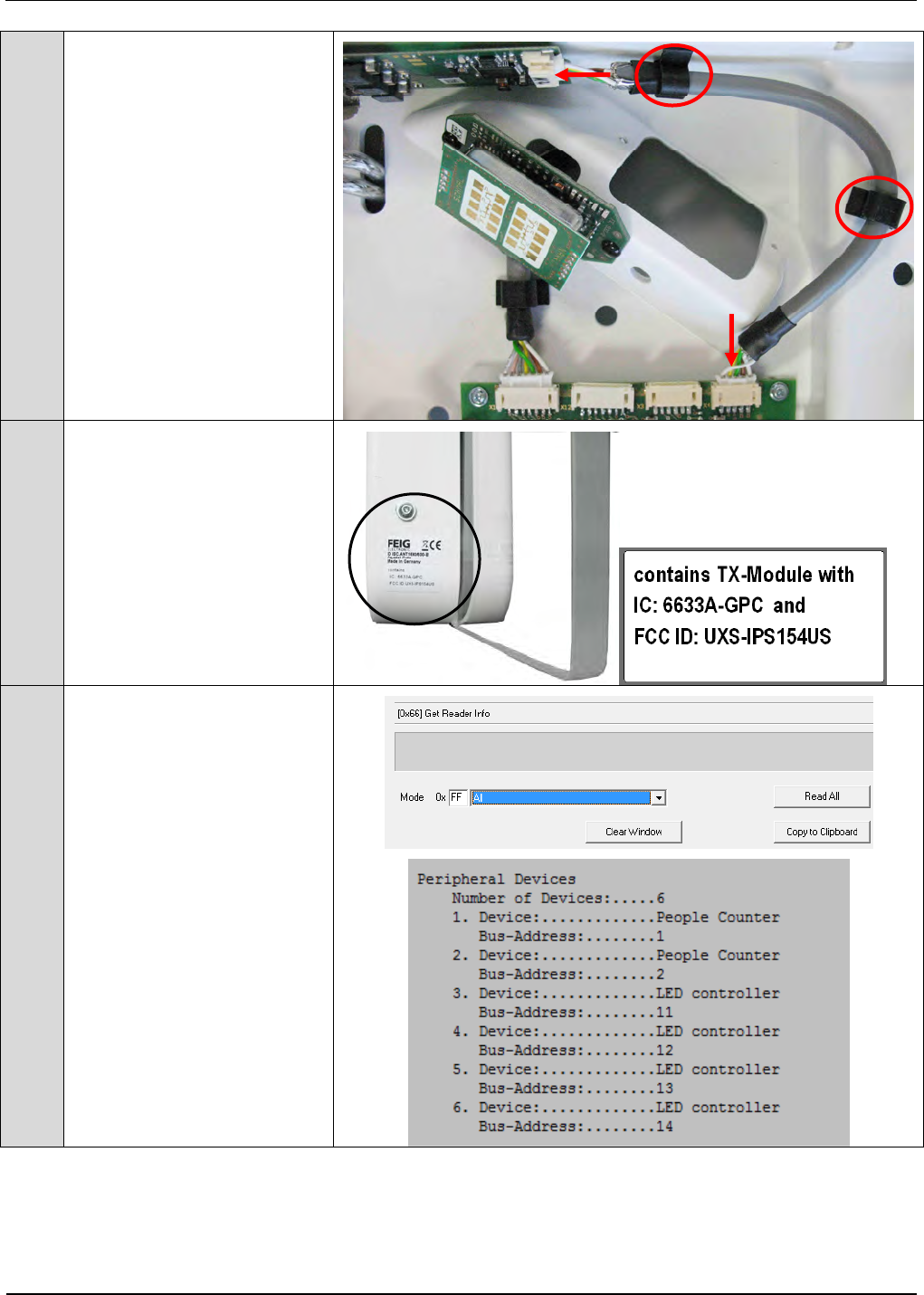
12.
Connect LED cable with X1
of LED controller and fix it
with the cable clips.
Connect the LED cable with
X3 of GPC
13.
Close antenna with antenna
cover with display window
After the installation you
have to stick the adhesive
label of the GPC below the
type plate of the antenna.
14.
The detection of the 2.and
3. GPC will be automatically
done after power up the
gate system or the com-
mand “System Reset” in
one of the Automatic
modes.
The successful detection
could be checked with the
command “Get reader Info”
“Read All” and will also be
displayed at the LCD-
display after power up or
command “System Reset”
IDENTIFICATION Installation ID ISC.ANT1520/680-A/-B
FEIG ELECTRONIC GmbH Page 63 of 82 ID ISC.ANT1520680-A-B User
Manual_M61112-1e-ID-E-
060317.doc
7.2 Configuration and Test
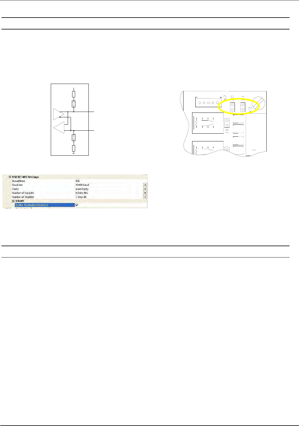
To activate the People Counters the following settings has to be done.
Set additional the Jumpers JP10 and J11 of Reader ID ISC.LRM2500-B to configure the RS485
interface. (see also manual M01111-xde-ID-B , page 54 and 55). The Termination has to be acti-
vated via software in the reader configuration.
J11
VCC
J10
500
Ω
500
Ω
RS485 +
RS485 -
Fig. 24: Jumper settings RS485 Interface
7.2.1 Connecting several People Counter
When using several People Counters (up to 3), at one reader, you have to connect the terminal
boards of all used antennas with each other in parallel. For the connection you have to use 5 (6)
pin shielded, twisted-pair cable. Example: LiYCY (TP) 3x2x0,25 .
The cable (2.5m) is contents of antenna Type B
The Bus address of the People Counter will be defined by the antenna number it is installed in.
GPC1 in Antenna No.1 = Bus address No. 1
GPC2 in antenna No.4 = Bus address No. 2
GPC3 in antenna No.6 = Bus address No. 3
The Bus address will be set automatically after setup and configuration of the complete gate
system after a “System Reset” command in one of the Automatic Modes.
The successful detection of the connected Gate People Counter could be checked with command
“Get Reader Info”

IDENTIFICATION Installation ID ISC.ANT1520/680-A/-B
FEIG ELECTRONIC GmbH Page 64 of 82 ID ISC.ANT1520680-A-B User
Manual_M61112-1e-ID-E-
060317.doc
The number of detected GPC and it´s firmware version will also be shown at the LCD-Display after
a power up or the command “System Reset” in one of the Automatic Modes.
IDENTIFICATION Installation ID ISC.ANT1520/680-A/-B
FEIG ELECTRONIC GmbH Page 65 of 82 ID ISC.ANT1520680-A-B User
Manual_M61112-1e-ID-E-
060317.doc
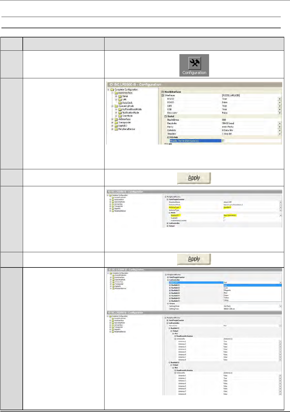
7.2.2 Configuration and Test in ISO-Host or Buffered Read
Step
Action Note
1 Select „Configuration“
2
Host Interface
Set RS 485 to “False” and
„Enable Termination
Resistors“
The RS232/485 Settings
should be set to:
Busaddress=0,
Baudrate=38400 baud,
Parity = even ,
Number of Databits = 8,
Number of Stopbits = 1
3 Confirm with „Apply“
4
Peripheral Devices
Gate People Counter
Set Antenna Type
“Standard”
Mode
Enable GPC to
„New Generation”
5 Confirm with „Apply“
6
Peripheral Device
LED Controller:
Setting Time:
„Setting Time“ set the dura-
tion time for the alarm.
(10 means 1 second)
(e.g. 10 x 100ms)
Set the colour for the
LED´s
Assign
LED Bus Address 11 to
antenna 1.
LED Bus Address 12 to
antenna 2.
......... and so on.
IDENTIFICATION Installation ID ISC.ANT1520/680-A/-B
FEIG ELECTRONIC GmbH Page 66 of 82 ID ISC.ANT1520680-A-B User
Manual_M61112-1e-ID-E-
060317.doc
„True“ means: LED with
Bus Address 11, 12, ... 17
will be active if the reader
read a valid transponder on
the corresponding antenna
7 Set by clicking on „Apply“.
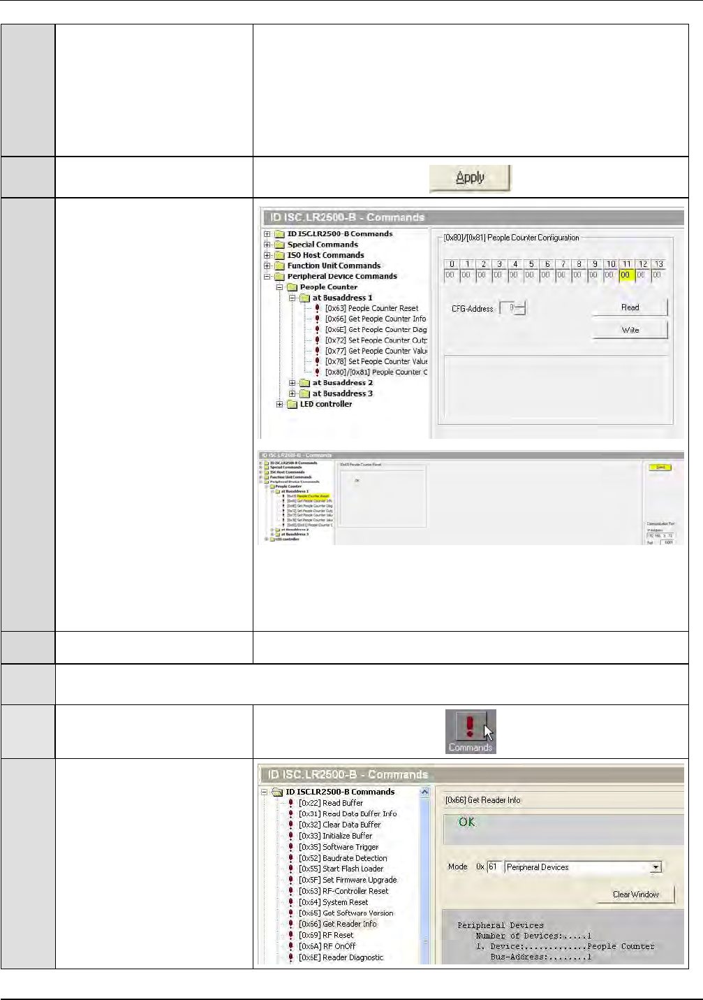
8
The sensitivity of the
connected radar modules
could be set by
- Peripheral Device
Commands, section,
- People Counter at
Busaddress 1,2 and 3
- Byte 11:
00 = Low
05 = Middle
0A = High
0F = Very high
First “Read” out actual
setting of sensitivity.
If needed change to new
sensitivity by “Write” the
new value into the GPC.
A “People Counter Reset”
command must be sent to
confirm the change,
otherwise the sensitivity will
not change.
Test: People Counter
9 Select „Commands“
10
Select Command
- „Get Reader Info“
- Peripheral Devices
1.
2.
IDENTIFICATION Installation ID ISC.ANT1520/680-A/-B
FEIG ELECTRONIC GmbH Page 67 of 82 ID ISC.ANT1520680-A-B User
Manual_M61112-1e-ID-E-
060317.doc
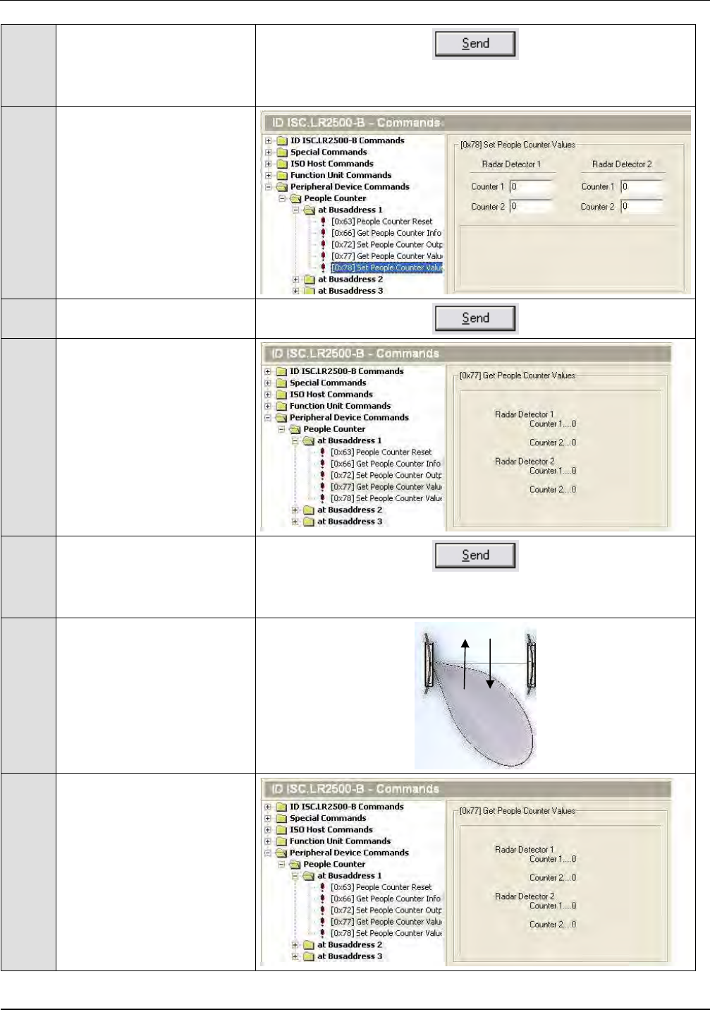
11
Confirm with „Send“
Number of Devices should
be 1
12
Select Command
„Set People Counter
Values“
13 Confirm with „Send“
14
Select Command
„Get People Counter
Values“
15
Confirm with „Send“
All counter values should
be 0
16
Walk through the gate from
both directions.
17
Select Command
„Get People Counter
Values“
Counter 1 | Counter 2
In | Out

IDENTIFICATION Installation ID ISC.ANT1520/680-A/-B
FEIG ELECTRONIC GmbH Page 68 of 82 ID ISC.ANT1520680-A-B User
Manual_M61112-1e-ID-E-
060317.doc
18 Confirm with „Send“
19
Counter values will be
displayed.
In ISO-Host and Buffered Read the People Counter has to be polled by the Host Application to get
the data.
IDENTIFICATION Installation ID ISC.ANT1520/680-A/-B
FEIG ELECTRONIC GmbH Page 69 of 82 ID ISC.ANT1520680-A-B User
Manual_M61112-1e-ID-E-
060317.doc
In Notification Mode the Reader sends the People Counter Data automatically to the Host.
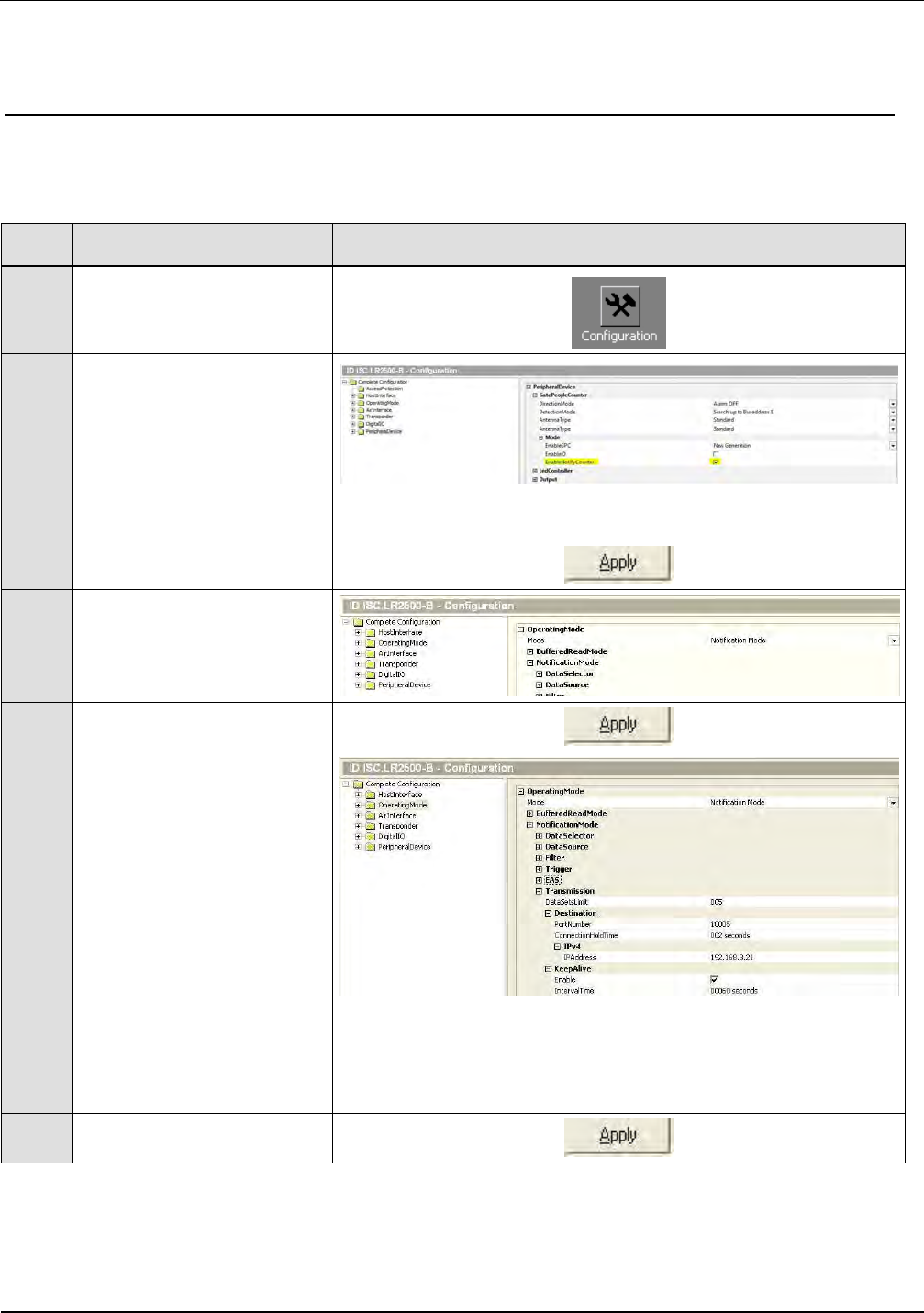
7.2.3 Configuration and Test in Notification Mode
The following configuration hast to be done:
Step
Action Note
1 Select „Configuration“
2
Peripheral Devices
GPC
Mode
Set “Enable Notify Counter”
3 Confirm with „Apply“
4
Operating Mode
Select
-Notification Mode
5 Confirm with „Apply“
6
Set IP Address and Port
for Notification Mode
IP Address of Host
e.g. here: 192.168.3.21
Port:10005
The same TCP/IP Address
and Port Address is valid for
the Notification Chanel of
the People Counter and
Notification Chanel of the
data
7 Confirm with „Apply“
IDENTIFICATION Installation ID ISC.ANT1520/680-A/-B
FEIG ELECTRONIC GmbH Page 70 of 82 ID ISC.ANT1520680-A-B User
Manual_M61112-1e-ID-E-
060317.doc
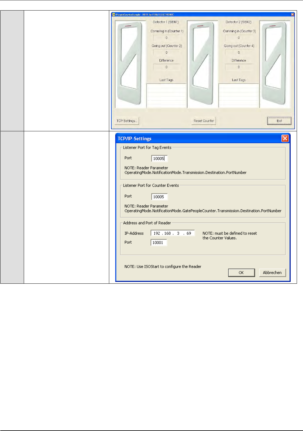
8
A Test could be done with
the People Counter
Sample.
9
Therefore you will have to
set both ports have the
same address, at the TCP-
Settings.
IDENTIFICATION Installation ID ISC.ANT1520/680-A/-B
FEIG ELECTRONIC GmbH Page 71 of 82 ID ISC.ANT1520680-A-B User
Manual_M61112-1e-ID-E-
060317.doc
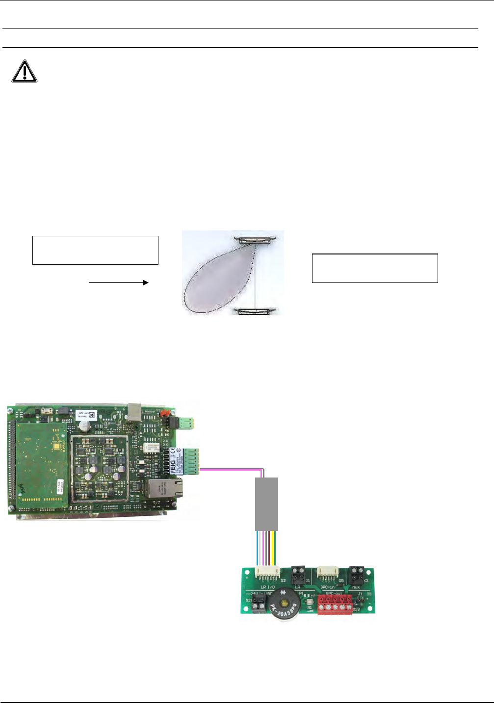
7.2.4 Using the trigger function of the Gate People Counter
The trigger function could only be used in one of the Automatic Modes.
The trigger function works bidirectional, but a 100% safe reading of transponder is only
possible from one direction. Due to this, it is necessary at the installation of the antennas,
that the Radar module / Antenna faces to the direction of the transponder which could
cause the alarm. At buildings (e.g. Libraries) the Radar module faces into the building.
Otherwise the reading of the transponder will just be started, when the person/transponder
is already in or outside the gate.
Fig. 25
Fig. 26
Valid Transponder
Exit of Building
Long Range Reader
ID ISC.LRM2500-B
X2 IN2+/IN2
-
ANT1520680-A
IDENTIFICATION Installation ID ISC.ANT1520/680-A/-B
FEIG ELECTRONIC GmbH Page 72 of 82 ID ISC.ANT1520680-A-B User
Manual_M61112-1e-ID-E-
060317.doc
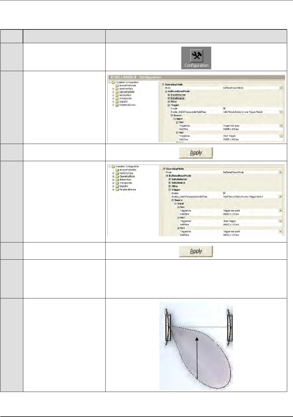
Step
Action Note
1 Select „Configuration“
2
Operating Mode
Select
-Buffered Read Mode
or
-Notification Mode
3 Confirm with „Apply“
4
Operating Mode
Set
-Trigger enable
-Source Input No 2-Trigger
TriggerUse set to
- Start Trigger
- Hold Time
e.g. 20x100ms =2sec.
5 Confirm with „Apply“
6
Multiplexer stops switching
of antennas. All Output
LED´s at Outputs of
Multiplexer are switched
off.
7
Walk through the gate.
Multiplexer/Gate will be
switch on for the set time.
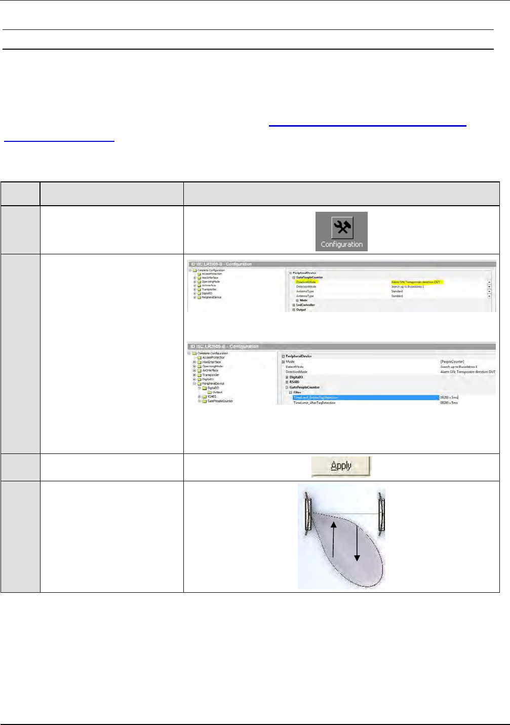
IDENTIFICATION Installation ID ISC.ANT1520/680-A/-B
FEIG ELECTRONIC GmbH Page 73 of 82 ID ISC.ANT1520680-A-B User
Manual_M61112-1e-ID-E-
060317.doc
7.2.5 Using the direction detection of transponder with the People Counter
In combination with the People Counter a direction detection of the transponders could be per-
formed in that way, that only transponder will cause an alarm which move in the configured direc-
tion through the gate. This should reduce false alarms.
It is mandatory that the trigger cable described in 7.2.4 Using the trigger function of the
Gate People Counter is connected to Input 2 of the reader and X4/TRG of the terminal
board, otherwise the direction mode will not work!
Step
Action Note
1
Select „Configuration“
2
Select Peripheral Devices
– Gate People Counter
Set Direction Mode to the
needed alarm direction.
Select Peripheral Devices
- Filter
Set Time Limit before and
after Tag Detection.
e.g. 200x5ms =1000ms
Time should be not to
short or to long !
3 Confirm with „Apply“
7
Walk through the gate with
a valid transponder and
check the alarm direction.
At multiple gates with more than two antennas, it is mandatory that the correct number
order of the connected antennas, alarm LED and people counter with radar module must be
observed. Setup, Connecting and Configuration hints could be found in the Application
Note N61211-xe-ID-E-pdf.

IDENTIFICATION Installation ID ISC.ANT1520/680-A/-B
FEIG ELECTRONIC GmbH Page 74 of 82 ID ISC.ANT1520680-A-B User
Manual_M61112-1e-ID-E-
060317.doc
8 Configure the reader in accordance with national RF regulations
Configuration of the RFID readers and the maximum transmitting power of the antennas are
affected mainly by the country-specific RF regulations. For the entire EU the limits are set forth in
the R&TTE Directive and EN 300 330.
The ID ISC.ANT1520/680 antenna with the ID ISC.LRM2500 Reader, when used as intended,
complies with the basic requirements of Article 3 and the other relevant clauses of the R&TTE
Directive 1999/5/EG of March 1999. This means that operation in the 27 EU countries and the
EFTA countries (EU countries plus Switzerland, Norway and Iceland) is possible with a maximum
field strength of 42 dBµA/m at 10 m distance.
RF approval (at a maximum field strength of 84 dBµV/m at 30 m) for the ID ISC.ANT1520/680
antenna with ID ISC.LRM2500 Reader has been granted in accordance with FCC Part 15 for the
USA and the RSS-210 for Canada
RF approval in accordance with EN 300 330 is still possible in all 46 CEPT countries.
The CEPT countries are:
Albania (ALB), Andorra (AND), Austria (AUT), Azerbaijan (AZE), Belarus (BLR), Belgium (BEL),
Bulgaria (BUL), Bosnia and Herzegovina (BIH), Croatia (HRV), Cyprus (CYP), Czech Republic
(CZE), Denmark (DNK), Estonia (EST), Finland (FIN), France (F), Germany (D), Greece (GRC),
Hungary (HNG), Iceland (ISL), Ireland (IRL), Italy (I), Latvia (LVA), Liechtenstein (LIE), Lithuania
(LTU), Luxembourg (LUX), Malta (MLT), Former Yugoslav Republic of Macedonia (MKD), Moldova
(MDA), Monaco (MCO), Netherlands (HOL), Norway (NOR), Poland (POL), Portugal (POR),
Romania (ROU), Russian Federation (RUS), San Marino (SMR), Slovak Republic (SVK), Slovenia
(SVN), Spain (E), Sweden (S), Switzerland (SUI), Turkey (TUR), Ukraine (UKR), United Kingdom
(G), Vatican City (CVA) and Yugoslavia.
The following restrictions are in effect (as of: October 2009):
1. Outside the EU and EFTA countries RF approval must in all cases be applied for. The existing
measuring protocols in accordance with EN 300 330 are generally sufficient.
When placing the antennas in service, the systems integrator must ensure that the prescribed
mounting instructions are followed, the necessary Reader settings are made and permissible limits
according to the national regulations are not exceeded.
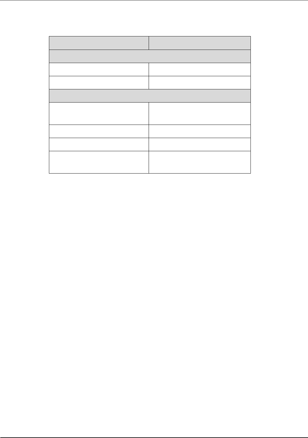
IDENTIFICATION Installation ID ISC.ANT1520/680-A/-B
FEIG ELECTRONIC GmbH Page 75 of 82 ID ISC.ANT1520680-A-B User
Manual_M61112-1e-ID-E-
060317.doc
The reader needs to be configured as follows depending on the installation location:
Parameter USA / Canada / Europe
Air Interface
RF-Power: maximum 8 W
RF Modulation: 15%
Transponder
RF Modulation / ISO-MODE /
MOD
10%
RF Data coding ISO-MODE: Fast (1/4) or Normal (1/256)
Timeslots ISO-MODE / NO-TS 1 or 16 Timeslots
ISO Option – BREAK: Complete Timeslot length at
„NO TAG“

IDENTIFICATION Installation ID ISC.ANT1520/680-A/-B
FEIG ELECTRONIC GmbH Page 76 of 82 ID ISC.ANT1520680-A-B User
Manual_M61112-1e-ID-E-
060317.doc
9 Technical Data
9.1 Antenna ID ISC.ANT1520/680 Type A and B
Mechanical Data
• Housing UV stabilized ABS and Acrylic
• Dimensions ( W x H x D )
– Antenna
– Packing
680 mm x 1798 mm x 76 mm ±
±±
± 3 mm
850 mm x 1920 mm x 162 mm ±
±±
± 10 mm
•
Weight
– ID ISC.ANT1520/680-A
– ID ISC.ANT1520/680-B
Approx. 29 kg without /33,5 kg with packing
Approx. 28 kg without /32,5 kg with packing
• Enclosure rating IP 41
• Colors
- Antenna frame
- Antenna base
acryl glass, clear transparent
white aluminum RAL 9006
•
Mounting
– No. of attaching points
– Recommended anchors
– Recommended minimum load
capacity of the floor fastener
2
∅
∅∅
∅ 10 mm
5000 N / anchor
• Maximum horizontal load on the top
edge of the antenna
250 N*
Electrical Data****
• Supply Voltage 24 V ±
±±
± 15 %
• Power Consumption max.70 VA
Stand by (Trigger function enabled)
8 VA
Operating (No alarm)
19,5 VA
Operating (Alarm LED+Buzzer switched on)
Single Gate 43 VA
Double Gate 48 VA
Triple Gate 58 VA
5 Antenna Gate 69 VA
6 Antenna Gate 65 VA
7 Antenna Gate 70 VA

IDENTIFICATION Installation ID ISC.ANT1520/680-A/-B
FEIG ELECTRONIC GmbH Page 77 of 82 ID ISC.ANT1520680-A-B User
Manual_M61112-1e-ID-E-
060317.doc
• Operating Frequency 13,56 MHz
• Maximum transmitting power per
antenna
8 W
• Permissible overall transmitting
power per antenna gate
– EU-territory (per EN 300 330)
– USA (per. FCC Part 15)
- Canada (per. RSS210)
8.0 W
8.0 W
8.0 W
• Outputs
– 1 Optocoupler
– 1 Optocoupler
– 1 Relay (NO)
Buzzer
Reader Synchronization
24 V / 1 A
• Inputs
– 1 Optocoupler
– 1 Optocoppler
Reader Synchronisation
Trigger
• Interfaces USB
Ethernet (TCP/IP)
• Protocol Modes FEIG ISO HOST
BRM (Data Filtering and Data Buffering)
Scan Mode (RS 232)
Notification Mode (TCP/IP)
• Supported Transponders ISO 15693, ISO 18000-3-A, (EM HF ISO
Chips, Fujitsu HF ISO Chips, KSW Sensor
Chips, Infineon my-d, NXP I-Code , STM ISO
Chips, TI Tag-it)
NXP I-Code 1
• Ranges / pass-through width in gate
with multiplexer
– One tag orientation
– All tag orientations
approx. 140 / 150 cm**
approx. 110 / 120 cm***
• Antenna connection 1 x SMA plug (50 Ω
ΩΩ
Ω)
• Antenna connector cable
- Type B
RG58, 50 Ω
ΩΩ
Ω, approx. 8,55 m long

IDENTIFICATION Installation ID ISC.ANT1520/680-A/-B
FEIG ELECTRONIC GmbH Page 78 of 82 ID ISC.ANT1520680-A-B User
Manual_M61112-1e-ID-E-
060317.doc
Ambient Conditions
• Temperature range
– Operating
– Storage
–25 °C to +50 °C
–25 °C to +70 °C
Applicable Standards
• RF approval
– Europe
– USA
- Canada
EN 300 330
FCC Part 15
RSS 210
• EMC EN 301 489
• Safety
– Low Voltage Directive
– Human Exposure
• Product testing
EN 60950-1
EN 50364
ISO 18046-4 / VDI-4478-1
* Persistent deformation after load release approx. 3 cm.
** Qty. 2 ID ISC.ANT1520/680-A/-B antennas, antenna spacing (antenna center), same flow direc-
tion, Tag 46 mm x 75 mm ISO15693, sensitivity / minimum field strength Hmin=60 / 40 mA/m rms,
transmitting power 8 W, tag orientation parallel to antenna for horizontal movement through the
antenna. The maximum antenna distance also depending of the strength of the Transponder an-
swer signal! Z.B NXP I-Code SLi-X / NXP I-Code SLi-S
*** Tag 46 mm x 75 mm ISO 15693, sensitivity / minimum field strength Hmin=60 / 40 mA/m rms,
transmitting power 8 W, aligned in all 3 dimensions for horizontal movement through the antenna.
The maximum antenna distance also depending of the strength of the Transponder answer signal!
Z.B NXP I-Code SLi / NXP I-Code SLi-S

IDENTIFICATION Installation ID ISC.ANT1520/680-A/-B
FEIG ELECTRONIC GmbH Page 79 of 82 ID ISC.ANT1520680-A-B User
Manual_M61112-1e-ID-E-
060317.doc
9.2 People Counter ID ISC.ANT.GPC and ID ISC.ANT.GPC-E2
Mechanical Data
• Housing Printed Boards
• Board Dimensions ( B x H x T )
– People Counter Board
– Radar Sensor Board
100 mm x 40 mm x 16 mm ±
±±
± 1 mm
60 mm x 30mm x 25 mm ±
±±
± 1 mm
•
Weight
– ID ISC.ANT.GPC
– ID ISC.ANT.GPC-E2
ca. 200 g / 250 g (0.55 lb) with packing
ca. 50 g / 100 g (0.22 lb) with packing
•
Mounting
– No. of attaching points
People Counter: 4 / Radar Sensor: 2
Electrical Data
• Supply Voltage • 24 V ±
±±
± 15 %
• Power Consumption • max. 2 VA
• Operating Frequency • 24,125 GHz
• RF-transmitting power • 16 dBm (e.i.r.p.)
• Temperature range
– Operation
– Storage
–25 °C to +55 °C
–25 °C to +85 °C
Functions
• Number of Aisles per People Counter
• Extension
1 or 2 aisle by using the second
radar module (ID ISC.ANT.GPC-E2)
up to 6 aisle =>2. People Counter
for the 3.+4. Aisle
3. People Counter
for the 5.+6. Aisle
• Direction detection Yes
• Counter per aisle
– 1 x direction 1 / In
– 1 x direction 2 / Out
0..4 294 967 295
0..4 294 967 295

IDENTIFICATION Installation ID ISC.ANT1520/680-A/-B
FEIG ELECTRONIC GmbH Page 80 of 82 ID ISC.ANT1520680-A-B User
Manual_M61112-1e-ID-E-
060317.doc

IDENTIFICATION Installation ID ISC.ANT1520/680-A/-B
FEIG ELECTRONIC GmbH Page 81 of 82 ID ISC.ANT1520680-A-B User
Manual_M61112-1e-ID-E-
060317.doc
9.3 Power Supply ID ISC.NET24V-B
Will be included in the packaging of the antenna ID ISC.ANT1520/680 Type HPDA
Mechanical Data
• Type Desktop power supply with IEC socket ac-
cording IEC60320-C13, 3-pin
• Housing Plastic
• Dimensions ( W x H x D ) 58 x 30,5 x 132 mm ±
±±
± 1 mm
• Weight Approx. 345g
• Enclosure rating IP 41
• Color Black
Electrical Data
• Supply voltage 110 – 240 VAC, 50-60 Hz
• Output voltage 24 V ±
±±
± 5 %
• Power consumption max. 3,0 A
• Output power max. 70 VA
• Electrical safety EN60950, UL60950
• Protection class I

IDENTIFICATION Installation ID ISC.ANT1520/680-A/-B
FEIG ELECTRONIC GmbH Page 82 of 82 ID ISC.ANT1520680-A-B User
Manual_M61112-1e-ID-E-
060317.doc
9.4 Approvals
As per Section 8
9.4.1 Europe (CE)
9.4.1.1 Antenne ID ISC.ANT1520/680-A/-B
This RF equipment is in compliance with the essential requirements and other relevant provisions
of Directive 1999/5/EC dated March 99.
Equipment Classification according to ETSI EN 300 330 and ETSI EN 301 489: Class 2
The technical data of the ID ISC.LRM2500-B Reader built into the ID ISC.ANT1520/680-A an-
tenna can be found in the Installation Manual which is included with the device.
9.4.1.2 People Counter ID ISC.ANT.GPC
This RF equipment is in compliance with the essential requirements and other relevant provisions
of Directive 1999/5/EC dated March 99.
Equipment Classification according to ETSI EN 300 330 and ETSI EN 301 489: Class 2

IDENTIFICATION Installation ID ISC.ANT1520/680-A/-B
FEIG ELECTRONIC GmbH Page 83 of 83 ID ISC.ANT1520680-A-B User
Manual_M61112-1e-ID-E-
060317.doc
9.4.2 USA (FCC) and Canada (IC)
9.4.2.1 Antenna ID ISC.ANT1520/680
Product name:
ID ISC.ANT1520/680
Antenna name:
ID ISC.ANT1520/680-A
ID ISC.ANT1520/680-B
Reader name:
ID ISC.LRM2500-B
FCC ID:
IC:
PJMLRM2500
6633A-LRM2500
Notice for USA and
Canada
This device complies with Part 15 of the FCC Rules and with
RSS-210 of Industry Canada.
Operation is subject to the following two conditions.
(1) this device may not cause harmful interference, and
(2) this device must accept any interference received,
including interference that may cause undesired operation.
Unauthorized modifications may void the authority granted under
Federal communications Commission Rules permitting the operation
of this device.
This equipment has been tested and found to comply with the limits for
a Class A digital device, pursuant to Part 15 of the FCC Rules. These
limits are designed to provide reasonable protection against harmful
interference when the equipment is operated in a commercial
environment. This equipment generates, uses, and can radiate radio
frequency energy and, if not installed and used in accordance with the
instruction manual, may cause harmful interference to radio
communications. Operation of this equipment in a residential area is
likely to cause harmful interference in which case the user will be
required to correct the interference at his own expense.
Le présent appareil est conforme aux CNR d'Industrie Canada appli-
cables aux appareils radio exempts de licence. L'exploitation est auto-
risée aux deux conditions suivantes :
(1) l'appareil ne doit pas produire de brouillage, et
(2) l'utilisateur de l'appareil doit accepter tout brouillage radioélectrique
subi, même si le brouillage est susceptible d'en compromettre le fonc-
tionnement.
Further information and technical data of the ID ISC.LRM2500-B Reader built into the
ID ISC.ANT1520/680 antenna can be found in the Installation Manual of the reader.

IDENTIFICATION Installation ID ISC.ANT1520/680-A/-B
FEIG ELECTRONIC GmbH Page 84 of 84 ID ISC.ANT1520680-A-B User
Manual_M61112-1e-ID-E-
060317.doc
9.4.2.2 People Counter ID ISC.ANT.GPC
FCC ID:
IC:
UXS-IPS154US
6633A-GPC
Notice for USA and
Canada
This device complies with Part 15 of the FCC Rules and with
RSS-210 of Industry Canada.
Operation is subject to the following two conditions.
(1) this device may not cause harmful interference, and
(2) this device must accept any interference received,
including interference that may cause undesired operation.
Unauthorized modifications may void the authority granted under
Federal communications Commission Rules permitting the operation
of this device.
This equipment has been tested and found to comply with the limits for
a Class A digital device, pursuant to Part 15 of the FCC Rules. These
limits are designed to provide reasonable protection against harmful
interference when the equipment is operated in a commercial
environment. This equipment generates, uses, and can radiate radio
frequency energy and, if not installed and used in accordance with the
instruction manual, may cause harmful interference to radio
communications. Operation of this equipment in a residential area is
likely to cause harmful interference in which case the user will be
required to correct the interference at his own expense.
Le présent appareil est conforme aux CNR d'Industrie Canada appli-
cables aux appareils radio exempts de licence. L'exploitation est auto-
risée aux deux conditions suivantes :
(1) l'appareil ne doit pas produire de brouillage, et
(2) l'utilisateur de l'appareil doit accepter tout brouillage radioélectrique
subi, même si le brouillage est susceptible d'en compromettre le fonc-
tionnement.
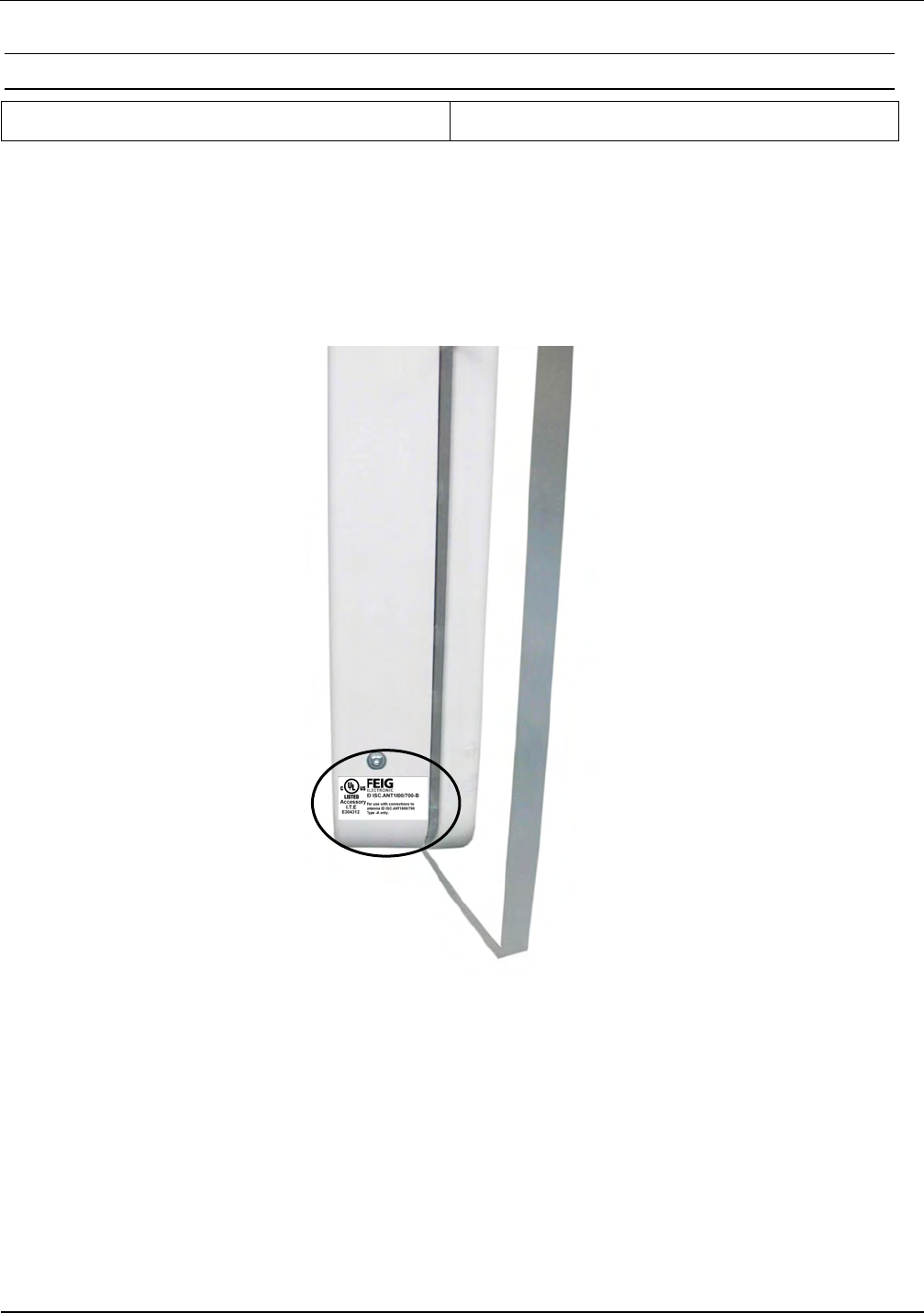
IDENTIFICATION Installation ID ISC.ANT1520/680-A/-B
FEIG ELECTRONIC GmbH Page 85 of 85 ID ISC.ANT1520680-A-B User
Manual_M61112-1e-ID-E-
060317.doc
9.4.3 USA and Canada (UL)
The following picture indicates the label position:
The following picture indicates the label position:

IDENTIFICATION Installation ID ISC.ANT1520/680-A/-B
FEIG ELECTRONIC GmbH Page 86 of 86 ID ISC.ANT1520680-A-B User
Manual_M61112-1e-ID-E-
060317.doc
10 Annex A
10.1 Terminal assignment “Terminal Board”
Terminal Acronym Description
X1 / LR 24V DC Reader
X1 / Pin 1 24V +24 V DC Reader
X1 / Pin 2 GND GND Reader
X2 / LR I/O 24V DC Input/Output , RS485
X2 / Pin 1 RS485 A-
X2 / Pin 2 RS485 B+
X2 / Pin 3 GND
X2 / Pin 4 TRG Trigger People Counter
X2 / Pin 5 GND
X2 / Pin 6 Buzzer
X2 / Pin 7 Shield
X3 / MUX 24V DC Multiplexer
X3 / Pin 1 24V +24 V DC Multiplexer
X3 / Pin 2 GND GND Multiplexer
X5 / GPC-in Connection Cable to People Counter or LED
X5 / Pin 1 +24V DC
X5 / Pin 2 GND People Counter or LED
X5 / Pin 3 RS485 A-
X5 / Pin 4 RS485B+
X5 / Pin 5 TRG Trigger People Counter
X5 / Pin 6 Shield
X11 24V DC Power Supply
X11 / Pin 1 24V Power Supply +24 V DC
X11 / Pin 2 - / GND Ground – Power Supply
X13 / GPC-out Connection Cable to next antenna
X13 / Pin 1 24V +24 V DC
X13 / Pin 2 GND GND

IDENTIFICATION Installation ID ISC.ANT1520/680-A/-B
FEIG ELECTRONIC GmbH Page 87 of 87 ID ISC.ANT1520680-A-B User
Manual_M61112-1e-ID-E-
060317.doc
X13 / Pin 3 TRG TRG Trigger People Counter
X13 / Pin 4 A- RS485 A-
X13 / Pin 5 B+ RS485 B+
Table 11: Pin-Configuration X1-X13 Terminal Board
10.2 Internal wiring
Terminal Acronym Description
X1 / LR 24V DC Reader
X1 / Pin 1 X13 +24 V DC Reader (red)
X1 / Pin 2 GND X13 GND Reader (black)
X2 / LR/I/O 24V DC Input/Output, RS485
X2 / Pin 1 Reader LR2500 X3 Pin RS485 B+ (green)
X2 / Pin 2 Reader LR2500 X3 Pin RS485 A- (yellow)
X2 / Pin 3 Reader LR2500 X2 Pin IN2- (pink)
X2 / Pin 4 Reader LR2500 X2 Pin IN2+ (grey)
X2 / Pin 5 Reader LR2500 X2 Pin Out2-E (brown)
X2 / Pin 6 Reader LR2500 X2 Pin Out2-C (white)
X2 / Pin 7 Reader LR2500 X2 GND (black/white)
X3 / MUX 24V DC Multiplexer
X3 / Pin 1 X1 +24 V DC Multiplexer (red)
X3 / Pin 2 GND X1 GND Multiplexer (black)
X5 / GPC-in Connection Cable to People Counter /LED
X5 / Pin 1 GPC X1 Pin 1 +24 V DC GPC/LED (white)
X5 / Pin 2 GPC X1 Pin 2 GND GPC/LED (brown)
X5 / Pin 3 GPC X1 Pin 3 RS485-A (green)
X5 / Pin 4 GPC X1 Pin 4 RS485+B (yellow)
X5 / Pin 5 GPC X1 Pin 5 TRG Trigger People Counter (grey)
X5 / Pin 6 GPC X1 Pin 6 Shield

IDENTIFICATION Installation ID ISC.ANT1520/680-A/-B
FEIG ELECTRONIC GmbH Page 88 of 88 ID ISC.ANT1520680-A-B User
Manual_M61112-1e-ID-E-
060317.doc