Feig Electronic LRU3000 RFID Reader User Manual LRU3000 Manual
Feig Electronic GmbH RFID Reader LRU3000 Manual
UserManual.wiki
>
Feig Electronic
>
LRU3000 User Manual
>
User Manual
Contents
1.
User Manual
2.
User Manaul II
3.
UM
User Manual
Navigation menu
Upload a User Manual
Namespaces
Wiki Guide
HTML
PDF
Info
Views
User Manual
Discussion / Help
Navigation
![OBID i-scan®Montage ID ISC.LRU3000FEIG ELECTRONIC GmbH Seite 19 von 52 LRU3000 - Manual.docD E U T S C H4 Bedien- und Anzeigeelemente4.1 Status LEDsGrün Gelb Rot BeschreibungAN AUS AN Bootvorgang (ca.10s) nach dem EinschaltenBLINKT AUS AUS Normaler Readerbetrieb (ohne Host Kommunikation)BLINKT BLINKT AUS Reader empfängt gültiges Protokoll vom HostBLINKT AUS AN RF Warning [0x84] (ohne Host Kommunikation)BLINKT(wechsel-seitig)AUS BLINKT(wechsel-seitig)Firmware Activation notwendig [0x17] /Wrong Firmware [0x18]BLINKT(gleichzeitig) AUS BLINKT(gleichzeitig) RFC Hardware Error [0xF1]AUS BLINKT(gleichzeitig)BLINKT(gleichzeitig)Hardware Warning(ACC EEPROM Error / RFC wird nicht detektiert)BLINKT AUS BLINKT(schnell) USB Host ErrorFirmware Update:BLINKT BLINKT BLINKT(Lauflicht)Firmware wird vom Host auf den Reader übertragen(Bitte Reader nicht ausschalten oder Interfacekabel ziehen)BLINKT BLINKT BLINKTgleichzeitigFirmware wird ins EEPROM programmiert.(Bitte Reader nicht ausschalten oder Interfacekabel ziehen)ANT 1- 4RUNHostKommunikation WarningInputOutput](https://usermanual.wiki/Feig-Electronic/LRU3000.User-Manual/User-Guide-1247418-Page-19.png)
![OBID i-scan®Montage ID ISC.LRU3000FEIG ELECTRONIC GmbH Seite 21 von 52 LRU3000 - Manual.docD E U T S C H4.3 Reader LeistungseinstellungUm hohe Lesereichweiten zu erreichen ist es notwendig, die Ausgangsleistung des Readers aufdie maximal erlaubte Ausgangsleistung einzustellen. Das ist abhängig von dem verwendeten Rea-der Typ (EU / FCC) und der Zulassung in dem jeweiligen Land, in dem der Reader verwendet wird.4.3.1 EU-Reader (EN 302 208)Nach der Norm EN 302 208 ist eine maximale abgestrahlte Leistung von 2 W e.r.p. (Effective Ra-diated Power) erlaubt. Die im Reader einzustellende Leistung Pout ist abhängig von der Kabel-dämpfung und dem Antennengewinn in dBi. Bei Verwendung einer zirkular polarisierte Antenne istder Gewinn ([G] = dBic) um 3 dB zu reduzieren. Bei einer linearen Antenne ist der maximale linea-re Gewinn ([G]= dBi) anzusetzen.POut = Pe.r.p. - Antennengewinn + Kabeldämpfung + 2,1dB**** Korrekturfaktor zur Umrechnung der abgestrahlten Leistung von e.r.p in e.i.r.pFür die Berechnung der am Reader einzustellenden Sendeleistung steht eine „Calc-RF-Power.xls“Excel Datei zur Verfügung. Verfügbar bei Feig Electronic GmbH.Beispiel:Tabelle 12: Berechnung der maximalen zulässigen Ausgangsleistung des Readers** lineare Antenne = „0“, zirkulare Antennen = „1“In Tabelle 12: Berechnung der maximalen zulässigen Ausgangsleistung des Readers wird die Be-rechnung der erlaubten Ausgangsleistung bei Verwendung der Antenne ANT.U600/270 -EU undeinem 6m langen Belden H155 Kabel dargestellt.](https://usermanual.wiki/Feig-Electronic/LRU3000.User-Manual/User-Guide-1247418-Page-21.png)
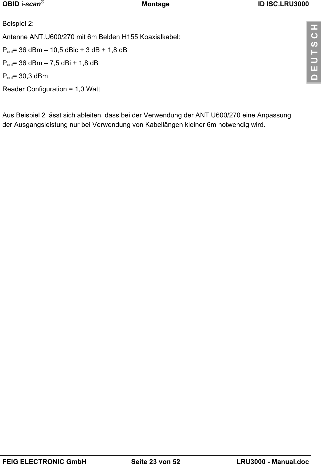
![OBID i-scan®Montage ID ISC.LRU3000FEIG ELECTRONIC GmbH Seite 22 von 52 LRU3000 - Manual.docD E U T S C H4.3.2 FCC-ReaderEntsprechend der FCC Zulassung, Title 47, Part15 ist an der SMA Buchse des Readers eine ma-ximale Ausgangsleistung von 1 W (30 dBm) zulässig. Die von der Antenne abgestrahlte Leistungdarf einen Wert von 4 W e.i.r.p nicht überschreiten.Daraus ergibt sich für linear polarisierte Antennen, deren Gewinn kleiner ist als 6 dBi, bzw. zirkularpolarisierte Antennen mit einem Gewinn kleiner 9 dBic, dass im Reader immer eine maximaleAusgangsleitung von 1 Watt konfiguriert werden darf.Antennengewinn < 6 dBi →POut = 1 WDies trifft zu bei der Verwendung der beiden FEIG Standardantennen ANT.U170/170 –FCC(4 dBic) und ANT.U270/270 –FCC (8,7 dBic).Werden Antennen mit einem größeren Gewinn als 6dBi (9 dBic) verwendet, so müssen bei derBerechnung der Ausgangsleistung des Readers der Antennengewinn und die Kabeldämpfung mitberücksichtigt werden. Wird eine zirkulare Antenne verwendet, so können 3dB von dem Antenne-gewinn [G]= dBic abgezogen werden. Dies trifft zu bei Verwendung der FEIG StandardantenneANT.U600/270. Bei solch einer Konstellation ergibt sich folgende Berechnung der Aus-gansgleistung des Readers:POut = 36 dBm (4 W e.i.r.p) – Antennengain (in dBi) + Kabeldämpfung (in dB)POut = 36 dBm (4 W e.i.r.p) – Antennengain (in dBic) – 3 dB + Kabeldämpfung (in dB)Der Antennengewinn der zirkular Polarisierten Antenne ANT.U600/270 beträgt 10,5 dBic. Diesentspricht einem Gewinn einer linearen Antenne von 7,5 dBi (10,5 dBic – 3 dB).Beispiel 1:Antenne ANT.U600/270 mit 2 m Belden H155 Koaxialkabel:Pout= 36 dBm – 10,5 dBic + 3 dB + 0,6 dBPout= 36 dBm – 7,5 dBi + 0,6 dBPout= 29,1 dBmReader Configuration = 0,8 Watt](https://usermanual.wiki/Feig-Electronic/LRU3000.User-Manual/User-Guide-1247418-Page-22.png)
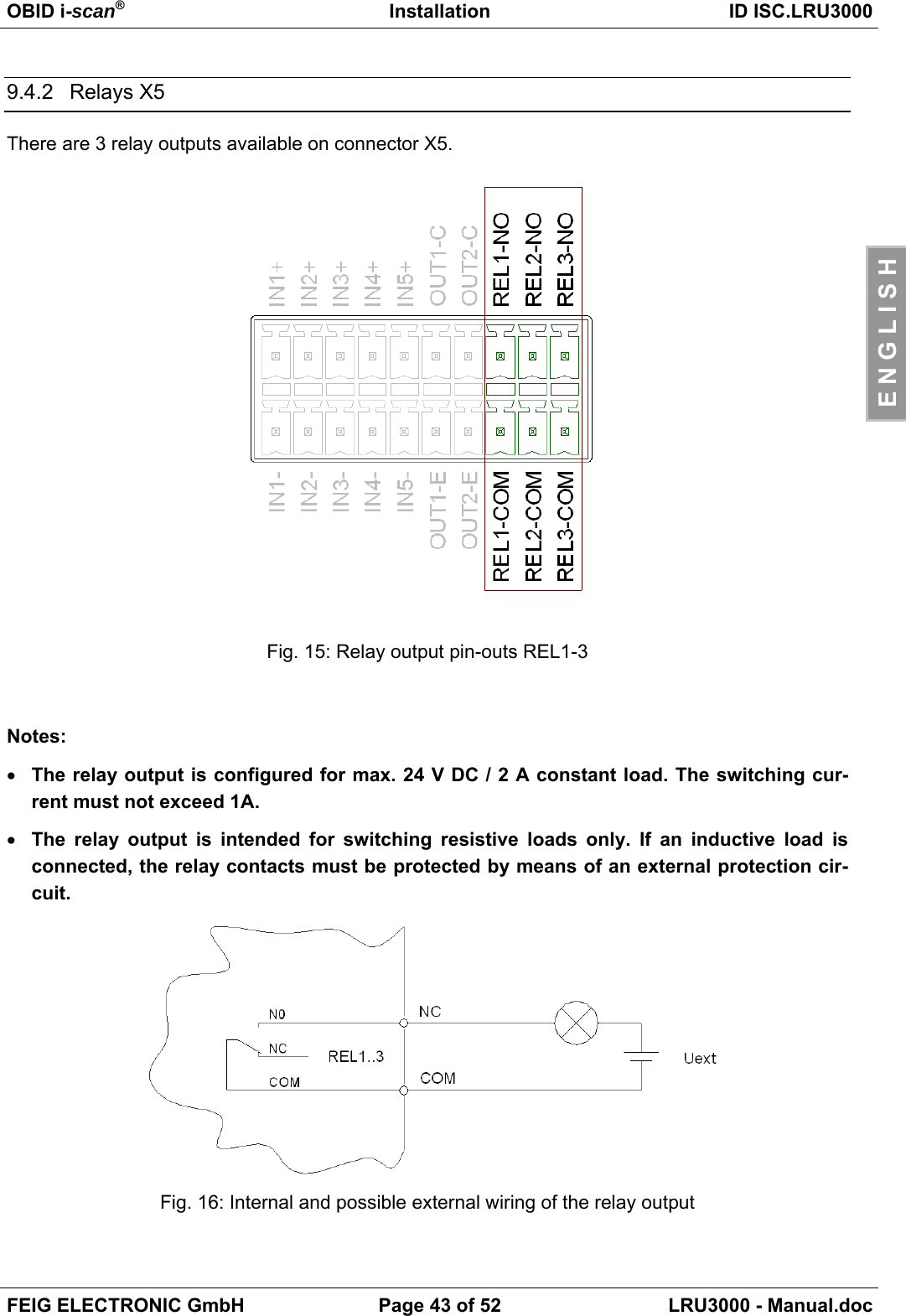
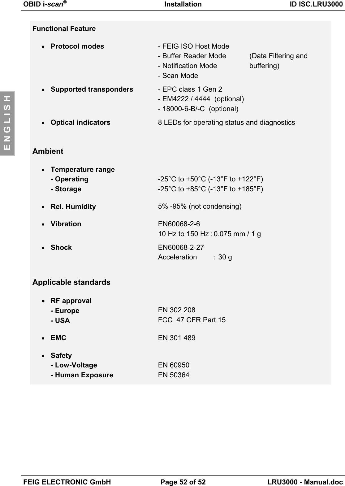
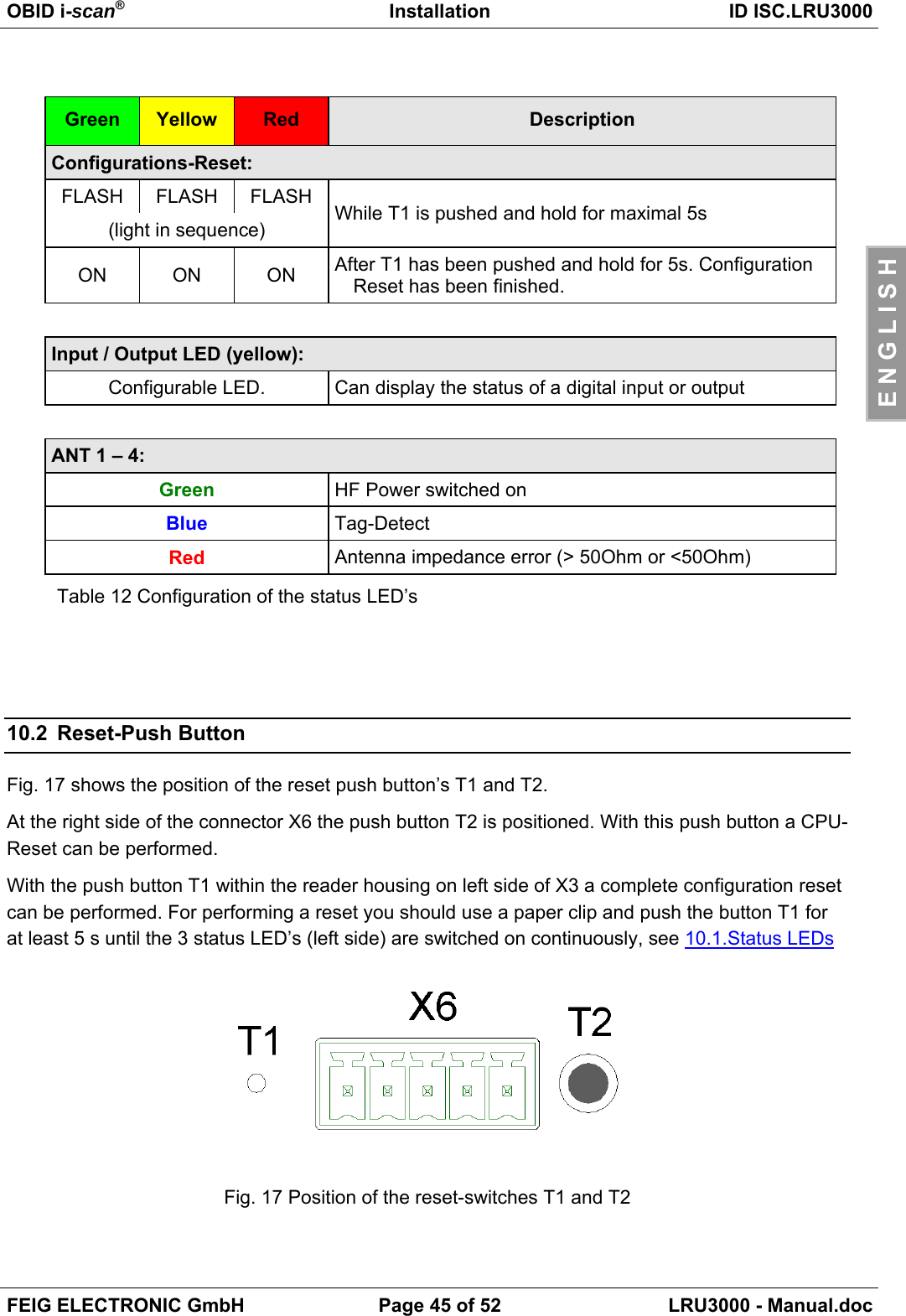
![OBID i-scan®Installation ID ISC.LRU3000FEIG ELECTRONIC GmbH Page 44 of 52 LRU3000 - Manual.docE N G L I S H10 Operating and Display Elements10.1 Status LEDsGreen Yellow Red DescriptionON OFF ON Boot sequence (ca.10s) after power onFLASH OFF OFF Normal Reader operation (without Host communication)FLASH BLINKT OFF Reader receives a valid protocol from hostFLASH OFF ON RF Warning [0x84] (without host communication)FLASH(alternat-ing)OFF FLASH(alternat-ing)Firmware Activation necessary [0x17] /Wrong Firmware [0x18]FLASH(synchro-nous)OFF FLASH(synchro-nous)RFC Hardware Error [0xF1]OFF FLASH(synchro-nous)FLASH(synchro-nous)Hardware Warning(ACC EEPROM Error / RFC not detected)FLASH OFF FLASH(fast) USB Host ErrorFirmware Update:FLASH FLASH FLASH(light in sequence)Firmware transfer from host to reader(Please do not switch off the reader or disconnect the interface cable)FLASH FLASH FLASHsynchronousFirmware flash into EEPROM.(Please do not switch off the reader or disconnect the interface cable)ANT 1- 4RUNHostCommunication WarningInputOutput](https://usermanual.wiki/Feig-Electronic/LRU3000.User-Manual/User-Guide-1247418-Page-44.png)
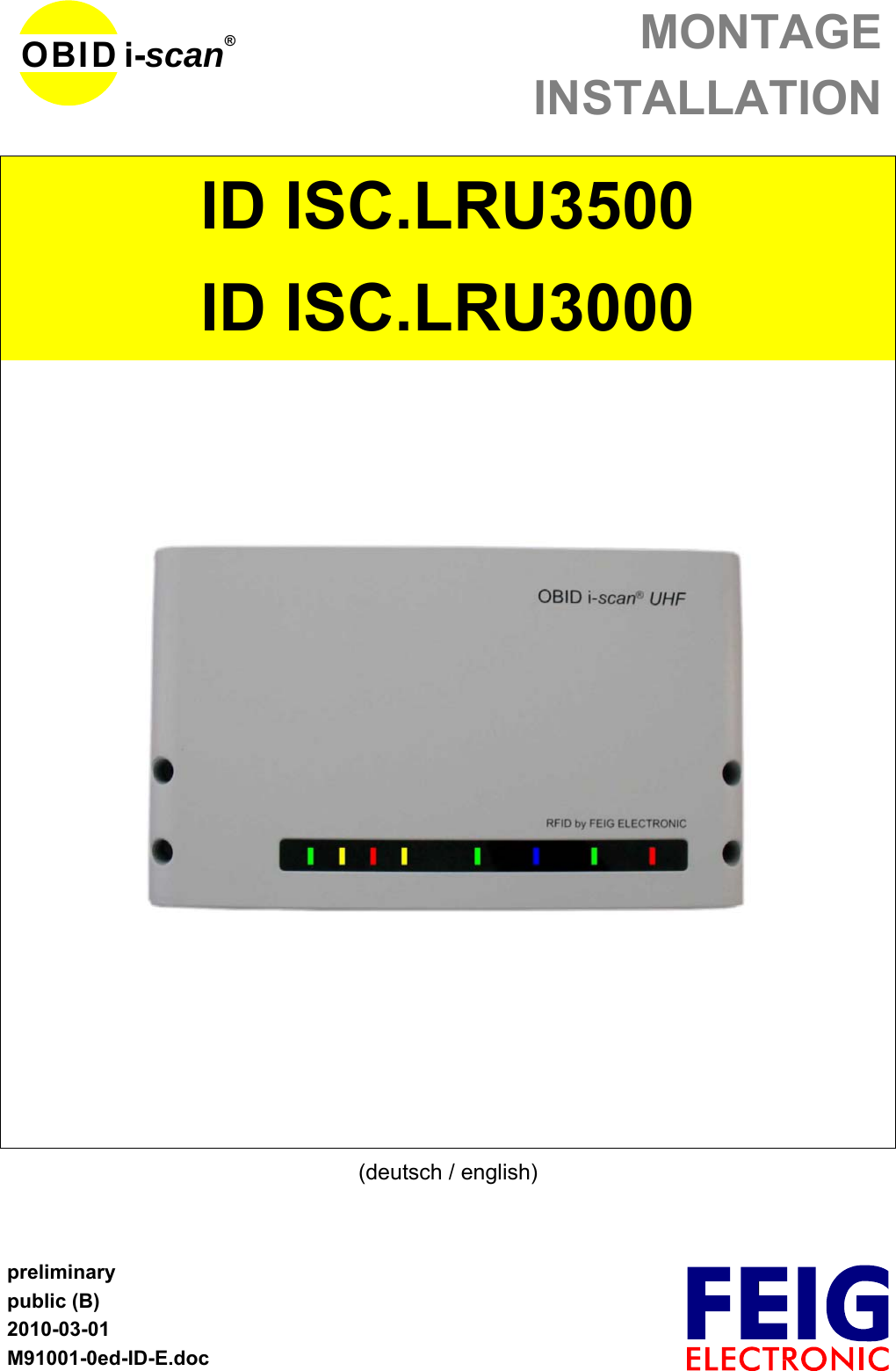
![OBID i-scan®Installation ID ISC.LRU3000FEIG ELECTRONIC GmbH Page 46 of 52 LRU3000 - Manual.docE N G L I S H10.3 Reader Power adjustmentTo achieve the optimum reading performance it is necessary to set the reader output power to thehighest allowed value. This depends on the used reader type (EU / FCC) and the regulation in thecountry were the reader is used.10.3.1 EU-Reader (EN302 208)According to the standard EN302 208 the maximum radiated power is 2 W e.r.p. (Effective Radi-ated Power) in countries of the European Union.The in the reader configured output power Pout depends on the antenna gain in dBi and the at-tenuation of the antenna cable. If a circular polarized antenna is used the antenna gain [dBic] canbe reduced by 3dB. At a linear polarized antenna the maximum linear antenna gain [dBi] must beused.POut = Perp - Antenna Gain + Cable loss + 2,1dB**** Correction Factor to convert the radiated power from e.r.p to e.i.r.p.For the calculation of the reader output power POut an Excel file „Calc-RF-Power.xls“ can be used.Available from Feig Electronic GmbH.Example:Table 13: Calculation of the output power** linear antenna = „0“, circular antenna = „1“In Table 13: Calculation of the output power the allowed antenna power is shown for the use of theFEIG standard antenna ANT.U600/270 –EU and a 6m long Belden H155 coaxial cable.](https://usermanual.wiki/Feig-Electronic/LRU3000.User-Manual/User-Guide-1247418-Page-46.png)
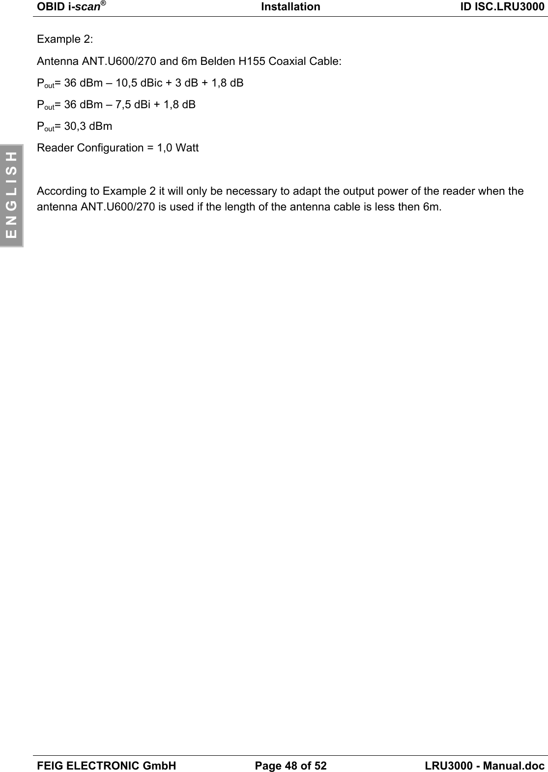
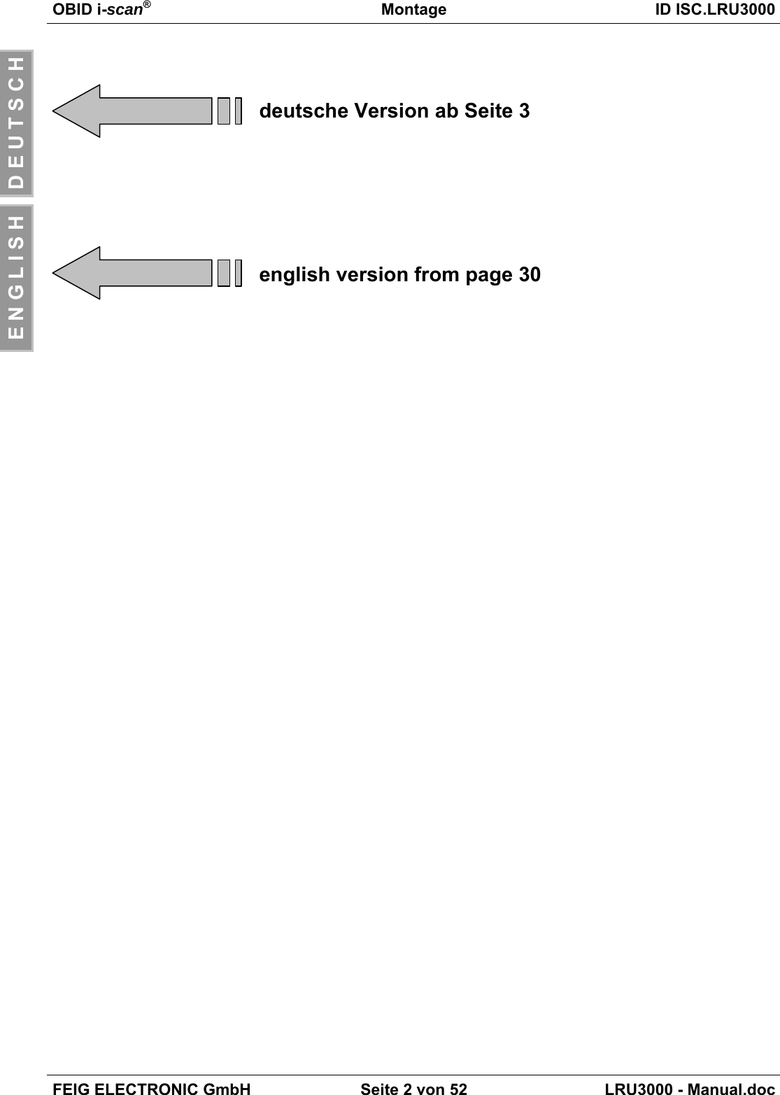
![OBID i-scan®Installation ID ISC.LRU3000FEIG ELECTRONIC GmbH Page 47 of 52 LRU3000 - Manual.docE N G L I S H10.3.2 FCC-ReaderAccording to the FCC approval, Title 47, Part15 the maximum output power of the reader is limitedto 1 W (30dBm). The maximum radiated power of the antenna should not increase more then 4 We.i.r.p.Due to these facts two different cases have to be considered:If a linear polarized antenna is used which gain is less then 6 dBi (factor 4), or if a circular polarizedantenna is used which gain is less then 9dBic the reader can always be configured to an outputpower of 1W.Antenna Gain < 6dBi →Pout = 1 WThis would be the case if the FEIG standard antennas ANT.U170/170 -FCC (4dBic) orANT.U270/270 -FCC (8,7dBic) are used.If an antenna is used which gain is more then 6dBi (9dBic) it is necessary to consider the antennagain and the attenuation of the antenna cable to calculate the right output power. If a circular po-larized antenna is used the antenna gain [G]=dBic can be reduced by 3dB. This is the case if theFEIG standard antenna ANT.U600/270 -FCC is used. In this configuration the maximum outputpower of the reader can be calculated in the following way.POut = 36 dBm (4 W e.i.r.p) – Antenna Gain (in dBi) + Cable Loss (in dB)POut = 36 dBm (4 W e.i.r.p) – Antenna Gain (in dBic) – 3 dB + Cable Loss (in dB)The antenna gain of the circular polarized standard antenna ANT.U600/270 is 10,5 dBic. Thiscould be compared with a gain of 7,5 dBi of a linear polarized antenna (10,5 dBic – 3 dB).Example :Antenna ANT.U600/270 and 2 m Belden H155 Coaxial Cable:Pout= 36 dBm – 10,5 dBic + 3 dB + 0,6 dBPout= 36 dBm – 7,5 dBi + 0,6 dBPout= 29,1 dBmReader Configuration = 0,8 Watt](https://usermanual.wiki/Feig-Electronic/LRU3000.User-Manual/User-Guide-1247418-Page-47.png)