Feig Electronic LRU3000 RFID Reader User Manual LRU3000 Manual
Feig Electronic GmbH RFID Reader LRU3000 Manual
Contents
- 1. User Manual
- 2. User Manaul II
- 3. UM
User Manual
MONTAGE
INSTALLATION
preliminary
public (B)
2010-03-01
M91001-0ed-ID-E.doc
OBI
D
i-scan
®
ID ISC.LRU3500
ID ISC.LRU3000
(deutsch / english)

OBID i-scan®Montage ID ISC.LRU3000
FEIG ELECTRONIC GmbH Seite 2 von 52 LRU3000 - Manual.doc
D E U T S C H
deutsche Version ab Seite 3
english version from page 30
E N G L I S H

OBID i-scan®Montage ID ISC.LRU3000
FEIG ELECTRONIC GmbH Seite 3 von 52 LRU3000 - Manual.doc
D E U T S C H
Hinweis
© Copyright 2009 by
FEIG ELECTRONIC GmbH
Lange Strasse 4
D-35781 Weilburg-Waldhausen
Tel.: +49 6471 3109-0
http://www.feig.de
Alle früheren Ausgaben verlieren mit dieser Ausgabe ihre Gültigkeit.
Die Angaben in diesem Dokument können ohne vorherige Ankündigung geändert werden.
Weitergabe sowie Vervielfältigung dieses Dokuments, Verwertung und Mitteilung ihres Inhalts sind nicht
gestattet, soweit nicht ausdrücklich zugestanden. Zuwiderhandlung verpflichtet zu Schadenersatz. Alle
Rechte für den Fall der Patenterteilung oder Gebrauchsmuster-Eintragung vorbehalten.
Die Zusammenstellung der Informationen in diesem Dokument erfolgt nach bestem Wissen und Gewissen.
FEIG ELECTRONIC GmbH übernimmt keine Gewährleistung für die Richtigkeit und Vollständigkeit der An-
gaben in diesem Dokument. Insbesondere kann FEIG ELECTRONIC GmbH nicht für Folgeschäden auf
Grund fehlerhafter oder unvollständiger Angaben haftbar gemacht werden. Da sich Fehler trotz aller Bemü-
hungen nie vollständig vermeiden lassen, sind wir für Hinweise jederzeit dankbar.
Die in diesem Dokument gemachten Installationsempfehlungen gehen von günstigsten Rahmenbedingun-
gen aus. FEIG ELECTRONIC GmbH übernimmt weder Gewähr für die einwandfreie Funktion in system-
fremden Umgebungen, noch für die Funktion eines Gesamtsystems, welches die in diesem Dokument be-
schriebenen Geräte enthält.
FEIG ELECTRONIC GmbH weist ausdrücklich darauf hin, dass die in diesem Dokument beschriebenen
Geräte nicht für den Einsatz mit oder in medizinischen Geräten oder für Geräte für lebenserhaltende Maß-
nahmen konzipiert sind, bei denen ein Fehler eine Gefahr für menschliches Leben oder für die gesundheitli-
che Unversehrtheit zur Folge haben kann. Der Applikationsdesigner ist dafür verantwortlich geeignete Maß-
nahmen zu ergreifen um Gefahren, Schäden oder Verletzungen zu vermeiden.
Geräte, die in diesem Dokument beschrieben werden, dürfen nicht im "Transport Markt" verkauft, benutz,
geleast, angeboten oder anderweitig übertragen, exportiert und importiert werden. Als "Transport Markt" sind
folgende Anwendungen definiert: (I) Elektronische Maut und Verkehrs Management (ETTM), (II) öffentliche
Kraftfahrzeugzulassung, -Registrierung und -Kontrolle (III), Verfolgung von schienengebundenen Lokomoti-
ven und Wagons (IV), erdgebundene Managementsysteme für Flughafen Transporte (GTMS) und Taxi Ab-
fertigung (V), kostenpflichtige Parksysteme und (VI) Fahrzeug initiierte mobile Bezahlsysteme, bei denen der
RFID Transponder bereits bei Auslieferung montiert ist, aber nicht beim Fahrzeughersteller in das Fahrzeug
integriert wurde.
FEIG ELECTRONIC GmbH übernimmt keine Gewährleistung dafür, dass die in diesem Dokument enthal-
tenden Informationen frei von fremden Schutzrechten sind. FEIG ELECTRONIC GmbH erteilt mit diesem
Dokument keine Lizenzen auf eigene oder fremde Patente oder andere Schutzrechte.
OBID® und OBID i-scan® ist ein eingetragenes Warenzeichen der FEIG ELECTRONIC GmbH

OBID i-scan®Montage ID ISC.LRU3000
FEIG ELECTRONIC GmbH Seite 4 von 52 LRU3000 - Manual.doc
D E U T S C H
Inhalt
1 Leistungsmerkmale der Readerfamilie ID ISC.LRU3000 6
1.1 Leistungsmerkmale.......................................................................................................6
1.2 Verfügbare Readertypen...............................................................................................6
1.3 Verfügbares Zubehör ....................................................................................................6
2 Montage 7
3 Anschlüsse 8
3.1 Antennenanschluss ......................................................................................................9
3.1.1 Versorgungsspannung über X1.......................................................................................9
3.2 Schnittstellen...............................................................................................................10
3.2.1 X2 Versorgungsspannung über PoE (Power over Ethernet) an X2 ..............................10
3.2.2 Ethernet-Schnittstelle an X2 (10/100Tbase)..................................................................11
3.2.3 USB – Schnittstelle X3 (Host Kommunikation)..............................................................12
3.2.4 USB – Schnittstelle X4 (WLAN).....................................................................................12
3.2.5 RS232-Schnittstelle X6 .................................................................................................13
3.2.6 RS485-Schnittstelle X6 .................................................................................................14
3.3 Digitale Eingänge X5...................................................................................................15
3.4 Ausgänge .....................................................................................................................17
3.4.1 Digitale Ausgänge X5....................................................................................................17
3.4.2 Relais X5 .......................................................................................................................18
4 Bedien- und Anzeigeelemente 19
4.1 Status LEDs .................................................................................................................19
4.2 Reset-Taster.................................................................................................................20
4.3 Reader Leistungseinstellung .....................................................................................21
4.3.1 EU-Reader (EN 302 208) ..............................................................................................21
4.3.2 FCC-Reader ..................................................................................................................22
5 Funkzulassungen 24
5.1 Europa (CE)..................................................................................................................24
5.2 USA (FCC) ....................................................................................................................25
6 Technische Daten 26

OBID i-scan®Montage ID ISC.LRU3000
FEIG ELECTRONIC GmbH Seite 5 von 52 LRU3000 - Manual.doc
D E U T S C H
Sicherheits- und Warnhinweise - vor Inbetriebnahme unbedingt lesen
• Das Gerät darf nur für den vom Hersteller vorgesehenen Zweck verwendet werden.
• Beim Aufstellen des Gerätes im Geltungsbereich der FCC 47 CFR Part 15 ist ein Mindestab-
stand von 25 cm zwischen Antenne und menschlichem Körper zu gewährleisten.
• Die Bedienungsanleitung ist zugriffsfähig aufzubewahren und jedem Benutzer auszuhändigen.
• Unzulässige Veränderungen und die Verwendung von Ersatzteilen und Zusatzeinrichtungen,
die nicht vom Hersteller des Gerätes verkauft oder empfohlen werden, können Brände, elektri-
sche Schläge und Verletzungen verursachen. Solche Maßnahmen führen daher zu einem
Ausschluss der Haftung und der Hersteller übernimmt keine Gewährleistung.
• Für das Gerät gelten die Gewährleistungsbestimmungen des Herstellers in der zum Zeitpunkt
des Kaufs gültigen Fassung. Für eine ungeeignete, falsche manuelle oder automatische Ein-
stellung von Parametern für ein Gerät bzw. ungeeignete Verwendung eines Gerätes wird keine
Haftung übernommen.
• Reparaturen dürfen nur vom Hersteller durchgeführt werden.
• Anschluss-, Inbetriebnahme-, Wartungs-, und sonstige Arbeiten am Gerät dürfen nur von Elekt-
rofachkräften mit einschlägiger Ausbildung erfolgen.
• Alle Arbeiten am Gerät und dessen Aufstellung müssen in Übereinstimmung mit den nationa-
len elektrischen Bestimmungen und den örtlichen Vorschriften durchgeführt werden.
• Beim Arbeiten an dem Gerät müssen die jeweils gültigen Sicherheitsvorschriften beachtet wer-
den.
• Besonderer Hinweis für Träger von Herzschrittmachern:
Obwohl dieses Gerät die zulässigen Grenzwerte für elektromagnetische Felder nicht über-
schreitet, sollten Sie einen Mindestabstand von 25 cm zwischen dem Gerät und Ihrem Herz-
schrittmacher einhalten und sich nicht für längere Zeit in unmittelbarer Nähe des Geräts bzw.
der Antenne aufhalten.
OBID i-scan®Montage ID ISC.LRU3000
FEIG ELECTRONIC GmbH Seite 6 von 52 LRU3000 - Manual.doc
D E U T S C H
1 Leistungsmerkmale der Readerfamilie ID ISC.LRU3500/3000
1.1 Leistungsmerkmale
Der Reader ist für das Lesen von passiven Datenträgern, sogenannten „Smart Labels“, mit einer
Betriebsfrequenz im UHF Bereich entwickelt.
1.2 Verfügbare Readertypen
Folgende Reader sind z.Z. verfügbar:
Readertyp Beschreibung
ID ISC.LRU3500-EU Gerätevariante für Europa mit PoE
ID ISC.LRU3000-EU Gerätevariante für Europa ohne PoE
ID ISC.LRU3500-FCC Gerätevariante für USA mit PoE
ID ISC.LRU3000-FCC Gerätevariante für USA ohne PoE
Tabelle 1: Readertypen
1.3 Verfügbares Zubehör
Folgendes optionales Readerzubehör ist z.Z. verfügbar:
Bezeichnung Beschreibung
ID ISC.LRU3000-PGM
Schutzkappe für PG Verschraubung für IP 64
Tabelle 2 Optionales Readerzubehör
OBID i-scan®Montage ID ISC.LRU3000
FEIG ELECTRONIC GmbH Seite 7 von 52 LRU3000 - Manual.doc
D E U T S C H
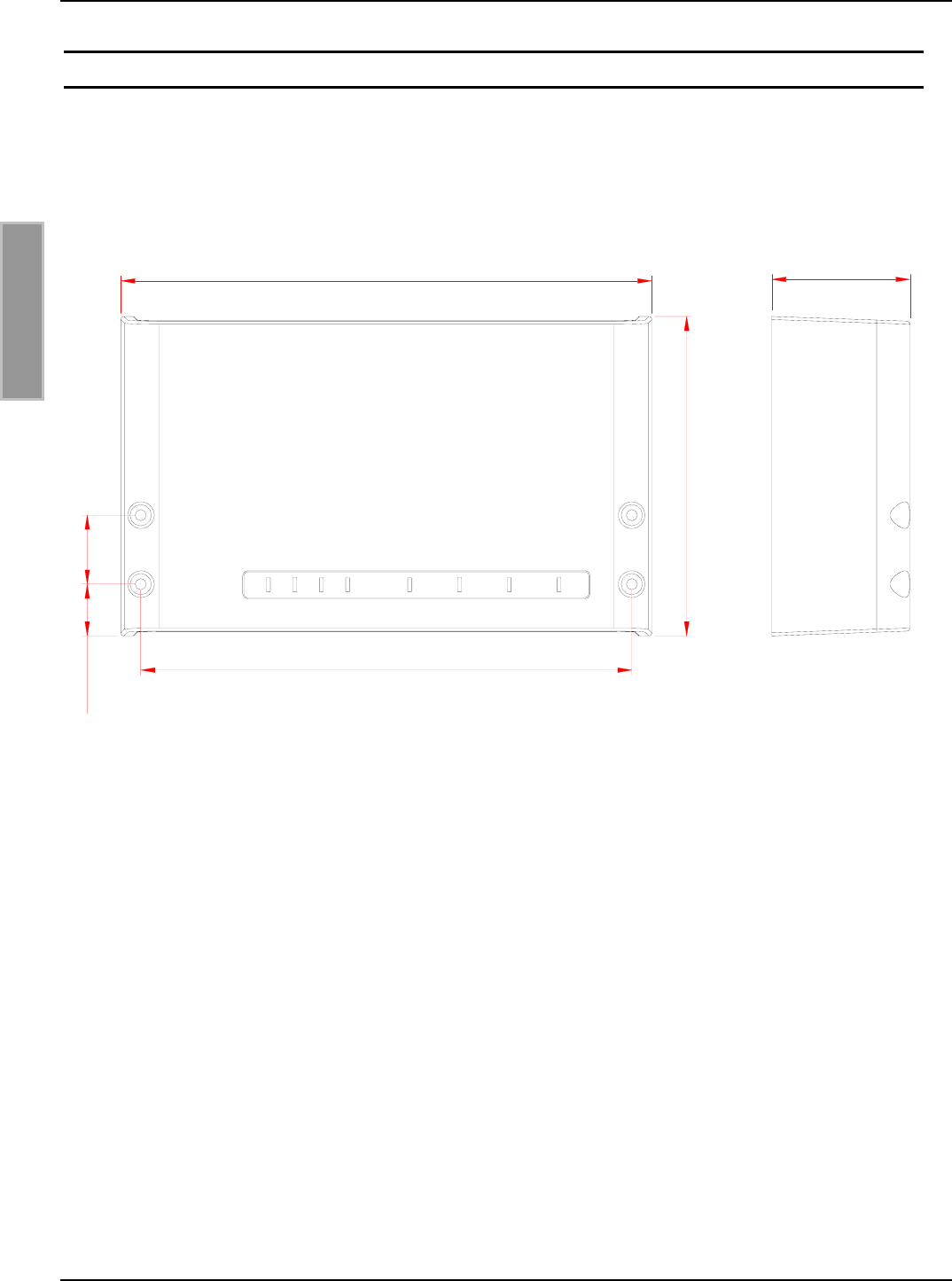
2 Montage
Der Reader ist für die Montage auf Wänden, auch im Freien, konzipiert. Zur Wandmontage befin-
den sich im Gehäuse vorgesehene Löcher.
Ein Aufschrauben des Gehäuses zur Montage ist nicht erforderlich.
261,3 (10.29)
157,3 (6.19)
241,7 (9.52)
34 (1.34)5,5 (1.00)
68 (2.68)
Bild 1 Montagezeichnung
OBID i-scan®Montage ID ISC.LRU3000
FEIG ELECTRONIC GmbH Seite 8 von 52 LRU3000 - Manual.doc
D E U T S C H
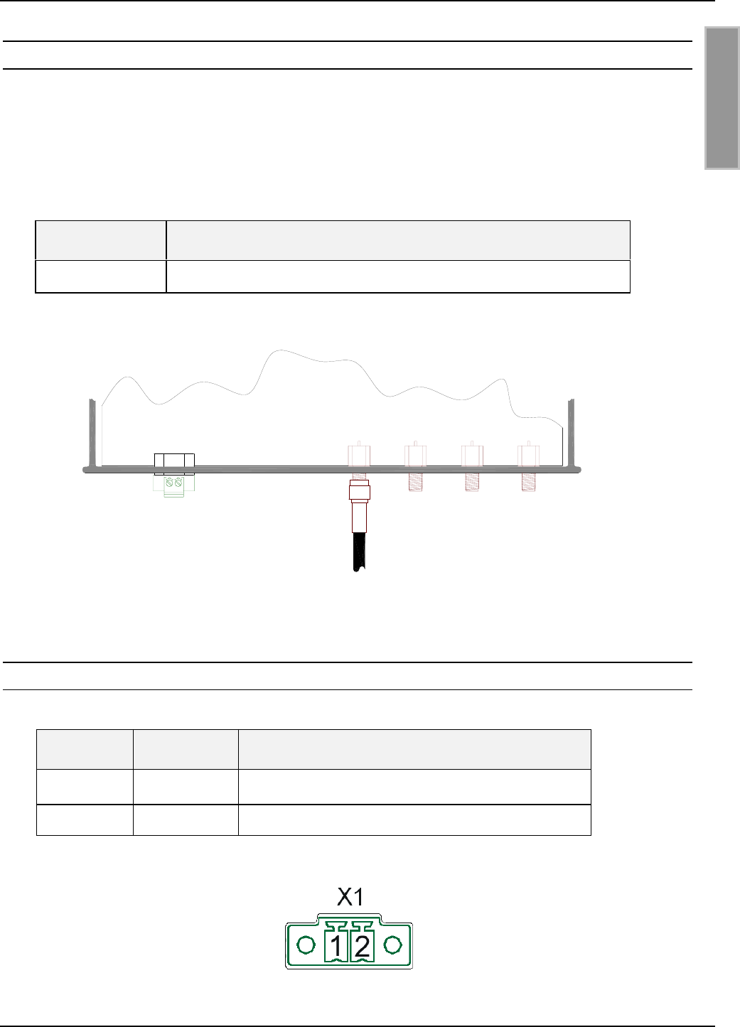
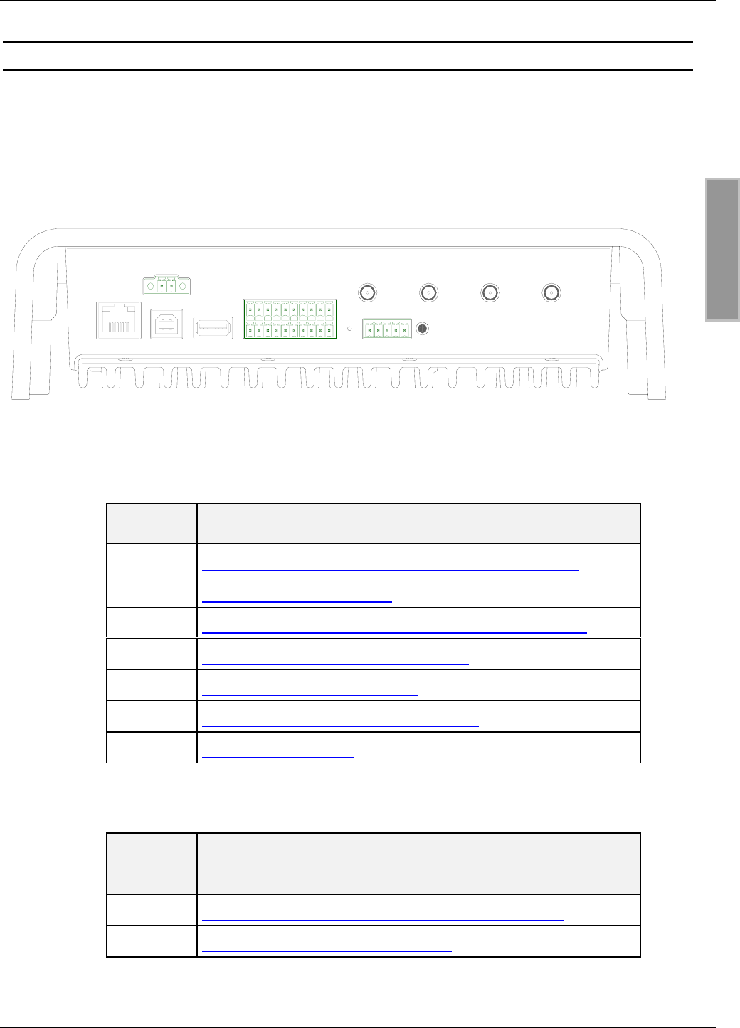
3 Anschlüsse
An der Unterseite des Gehäuses befinden sich die Kabelanschlüsse. Bild 2: Anschlussübersicht
zeigt die Anordnung und in Tabelle 3 Anschlussklemmen ist dargestellt, welche Anschlüsse für die
einzelnen Leitungen verwendet werden sollen.
In Tabelle 4 sind die verfügbaren Taster aufgelistet.
X2 X3 X4
X5
X6
T1 T2
X1 ANT1 ANT2 ANT3 ANT4
Bild 2: Anschlussübersicht
Anschluss Beschreibung
ANT 1-4 Anschluss der externen Antennen (Eingangsimpedanz 50Ω)
X1 Versorgungsspannung 24VDC ± 5%
X2 10/100Tbase Netzwerkschnittstelle mit RJ-45 (mit PoE)
X3 USB Schnittstelle für Host-Kommunikation
X4 USB Schnittstelle für WLAN-Stick
X5 Digitale Ein- und Ausgänge und Relaisanschlüsse
X6 RS232 / 485 Schnittstelle
Tabelle 3 Anschlussklemmen
Taster Beschreibung
T1 Interne Taste für Konfigurations-Reset (komplett)
T2 Externe Taste für CPU-Reset
Tabelle 4 Tasten-Funktion
OBID i-scan®Montage ID ISC.LRU3000
FEIG ELECTRONIC GmbH Seite 9 von 52 LRU3000 - Manual.doc
D E U T S C H
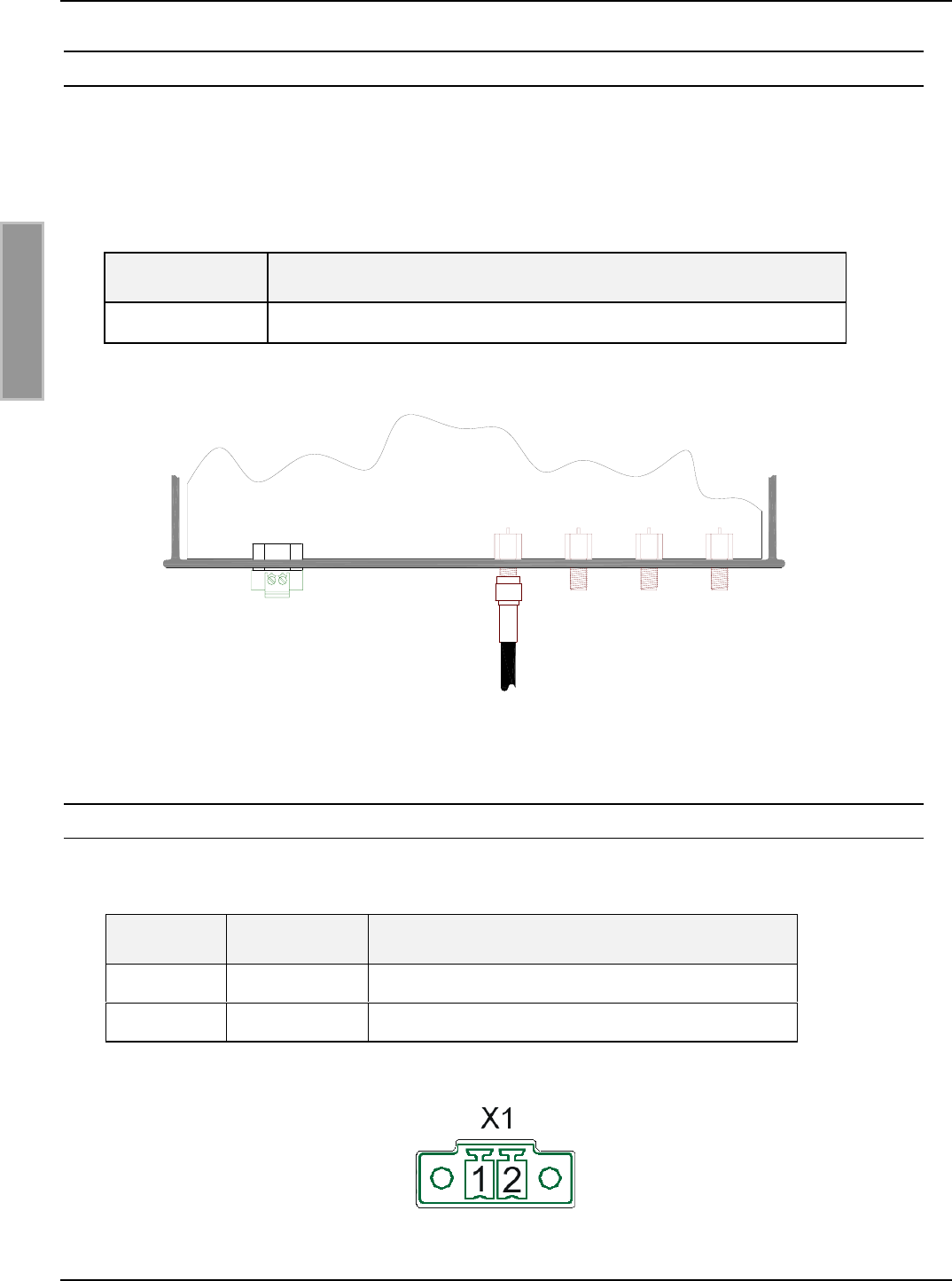
3.1 Antennenanschluss
Die SMA-Buchsen für den Anschluss der externen Antennen befindet sich ebenfalls auf der Unter-
seite des Readers
Das maximale Anzugsdrehmoment der SMA-Buchsen beträgt 0,45 Nm.
Achtung:
Höhere Anzugsdrehmomente führen zur Zerstörung des Steckers.
Klemme Beschreibung
ANT 1-4 Anschluss der externen Antennen (Eingangsimpedanz 50 Ω)
Tabelle 5: Anschluss der externen Antennen
Bild 3 Antennenanschlüsse ANT1-4 und X1 für die Versorgungsspannung
3.1.1 Versorgungsspannung über X1
Die Versorgungsspannung von 24 VDC ist an der Klemme X1 anzuschließen.
Klemme Kurzzeichen Beschreibung
X1 / Pin 1 VDC Vcc – Versorgungsspannung 24V DC ± 5%
X1 / Pin 2 GND Ground – Versorgungsspannung
Tabelle 6: Pinbelegung Versorgungsspannung
Bild 4: Anschluss der Versorgungsspannung
ANT1 ANT2 ANT3 ANT4
X1
OBID i-scan®Montage ID ISC.LRU3000
FEIG ELECTRONIC GmbH Seite 10 von 52 LRU3000 - Manual.doc
D E U T S C H
3.2 Schnittstellen
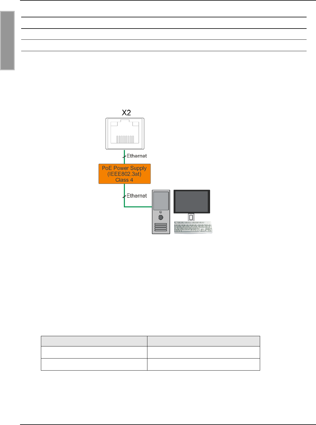
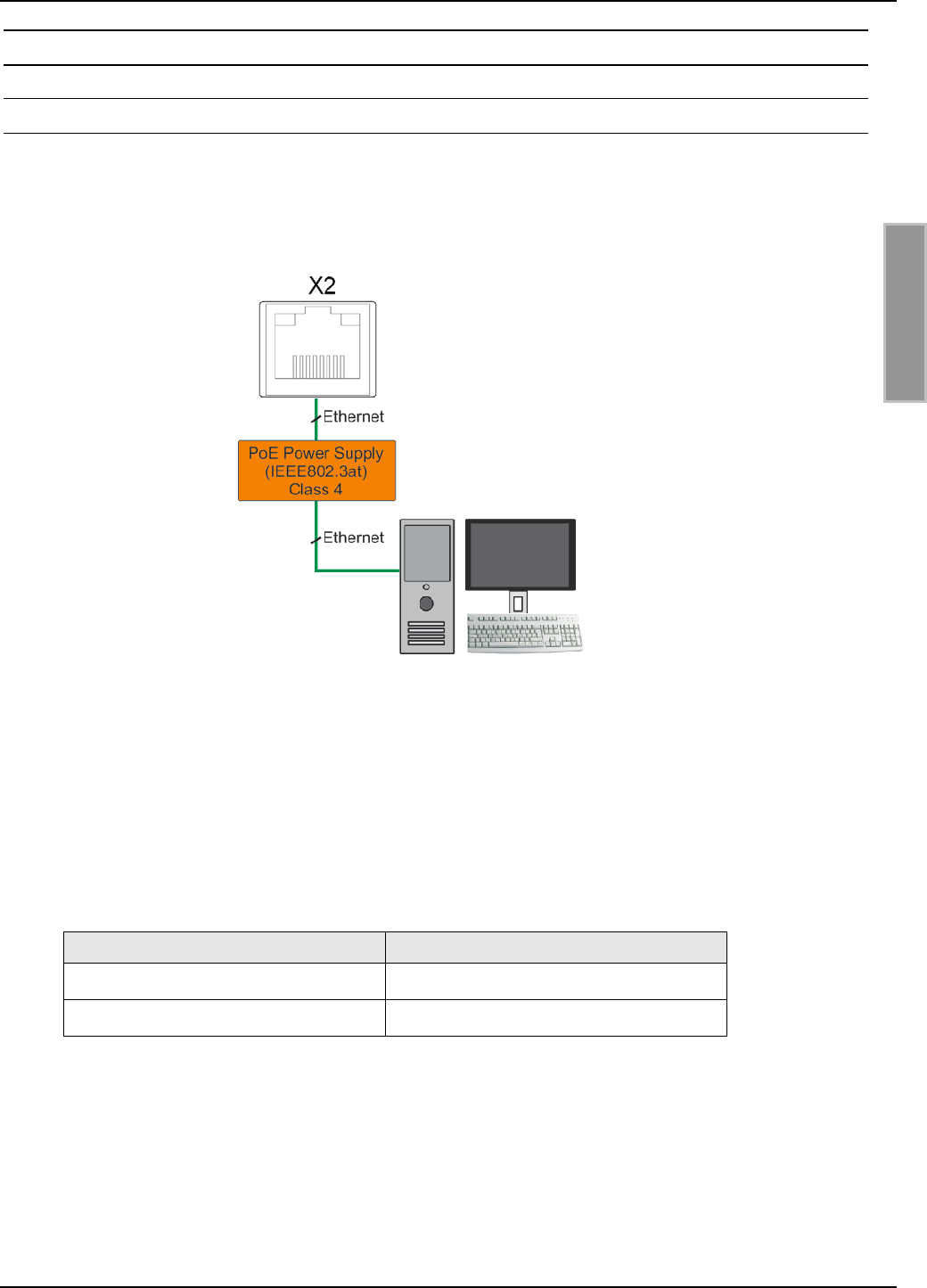
3.2.1 X2 Versorgungsspannung über PoE (Power over Ethernet) an X2
Alternativ kann der Reader über den LAN-Anschluss X2 mit Hilfe eines „Power over Ethernet“-
Netzteil gem. IEEE802.3at*, Class4 (30/25,5Watt) versorgt werden. Die DC Speisung kann über
die freien Pin’s 4,5 und 7,8 erfolgen (Midspan-Power), als auch eine „Phantomspeisung“ über die
Signalverbindung 1,2,3 und 6 ist möglich (Inline-Power).
Bild 5 LAN und PoE Anschluss
Hinweis
• Wenn der Reader über PoE versorgt wird, ist darauf zu achten das die maximale Aus-
gangsleistung des Readers auf 1 Watt zu begrenzen ist.
• Es ist sicherzustellen das der Reader mit mindestens 42,5 V (48 VDC – Leitungsverluste)
versorgt wird.
Abhängig vom Leitungsquerschnitt sind folgende maximale Leitungslängen möglich:
Leitungsquerschnitt (CAT5...7) Maximale Leitungslänge für PoE
0,4 mm ≈ 30 m
0,6 mm ≈ 70 m
* Detaillierte technische Informationen zu dem Standard 802.3at können der aktuellen Version der
entsprechenden IEEE Spezifikation entnommen werden.

OBID i-scan®Montage ID ISC.LRU3000
FEIG ELECTRONIC GmbH Seite 11 von 52 LRU3000 - Manual.doc
D E U T S C H
3.2.2 Ethernet-Schnittstelle an X2 (10/100Tbase)
Der Reader verfügt über eine integrierte 10/100 base-T Netzwerkschnittstelle mit standard RJ-45-
Anschluss. Der Anschluss erfolgt über X2 und hat eine automatische „Crossover Detection“ ent-
sprechend dem 1000BASE-T Standard.
Bei einer strukturierten Verkabelung sollten mindestens Kabel der Kategorie CAT5 verwendet wer-
den. Dies garantiert einen problemlosen Betrieb bei 10 Mbps oder 100 Mbps.
Vorraussetzung für den Einsatz des TCP/IP-Protokolls ist, dass jedes Gerät am Netzwerk über
eine eigene IP-Adresse verfügt. Alle Reader verfügen über eine werksseitig voreingestellte
IP-Adresse.
Netzwerk Adresse
IP-Adresse 192.168.10.10
Subnet-Mask 255.255.255.0
Port 10001
DHCP AUS
Tabelle 7 Werkskonfiguration der Ethernet-Schnittstelle
Hinweis:
Der Reader verfügt über eine DHCP-fähige TCP/IP Schnittstelle.
OBID i-scan®Montage ID ISC.LRU3000
FEIG ELECTRONIC GmbH Seite 12 von 52 LRU3000 - Manual.doc
D E U T S C H
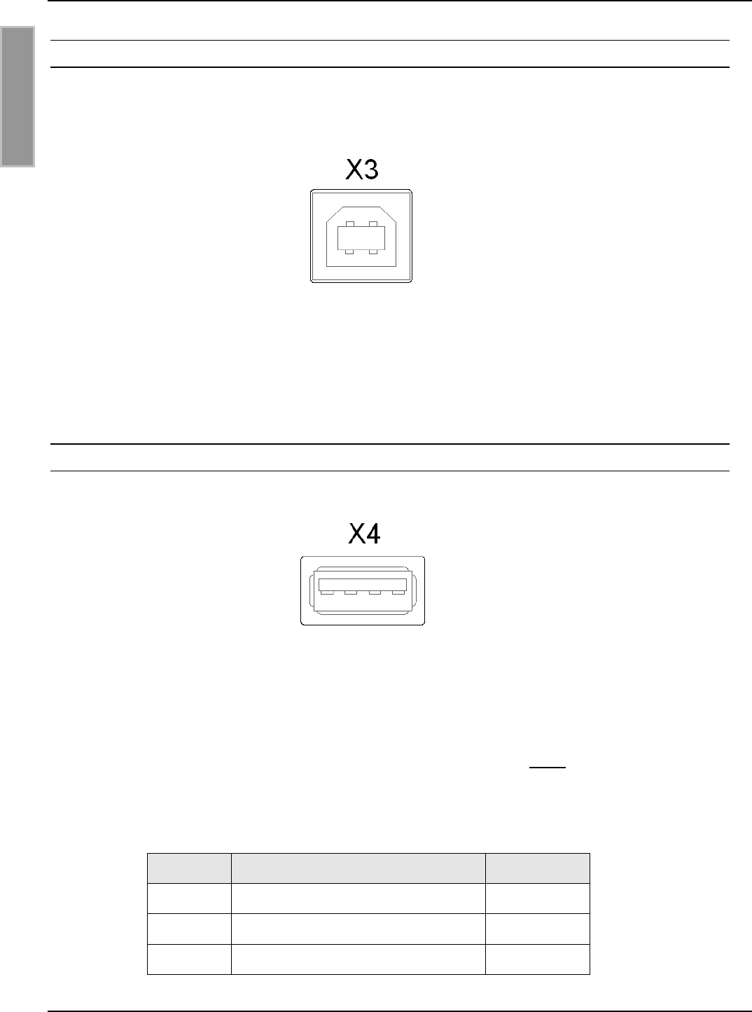
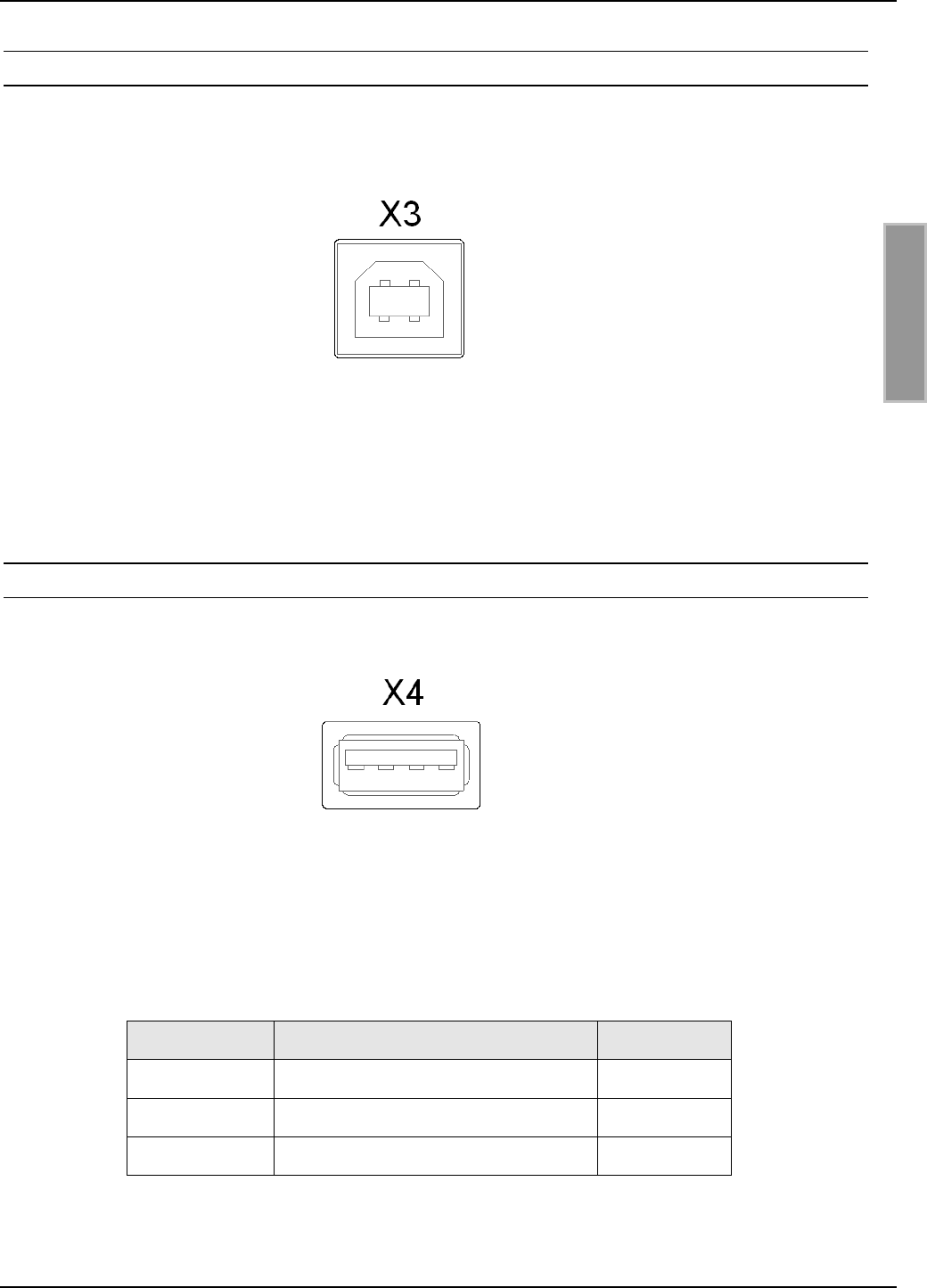
3.2.3 USB – Schnittstelle X3 (Host Kommunikation)
Der Anschluss der USB-Schnittstelle erfolgt über Buchse X3. Die Belegung ist genormt. Die Daten-
rate des Readers ist auf 12 Mbit beschränkt (USB Full Speed). Es kann ein Standard-USB-Kabel
verwendet werden.
Bild 6 USB-Schnittstelle für Host Kommunikation
Hinweis:
Die maximale Länge des USB-Kabels darf 5 m betragen. Längere Kabel sind nicht erlaubt.
3.2.4 USB – Schnittstelle X4 (WLAN)
Der USB Anschluss kann für ein standard WLAN-Sticks genutzt werden.
Bild 7 USB-Schnittstelle für externes WLAN Interface
Hinweis:
• Es können handelübliche WLAN Sticks eingesetzt werden, die über einen „Ralink“ Chip-
satz „RT2500 USB“ oder „RT73“ verfügen.
• Der WLAN-Stick darf nur eingesetzt werden wenn der Reader nicht über PoE versorgt
wird.
Zum Beispiel wurden folgende WLAN Stick erfolgreich mit dem ID ISC.LRU3000 getestet:
Hersteller Bezeichnung Model
Gigabyte Air Cruiser G USB Adapter GN-WBKG
ASUS USB2.0 WLAN Adapter WL-167G
Linksys Kompakt Wireless-G USB Adapter WUSB54GC
Tabelle 8 Getestete WLAN Sticks
OBID i-scan®Montage ID ISC.LRU3000
FEIG ELECTRONIC GmbH Seite 13 von 52 LRU3000 - Manual.doc
D E U T S C H
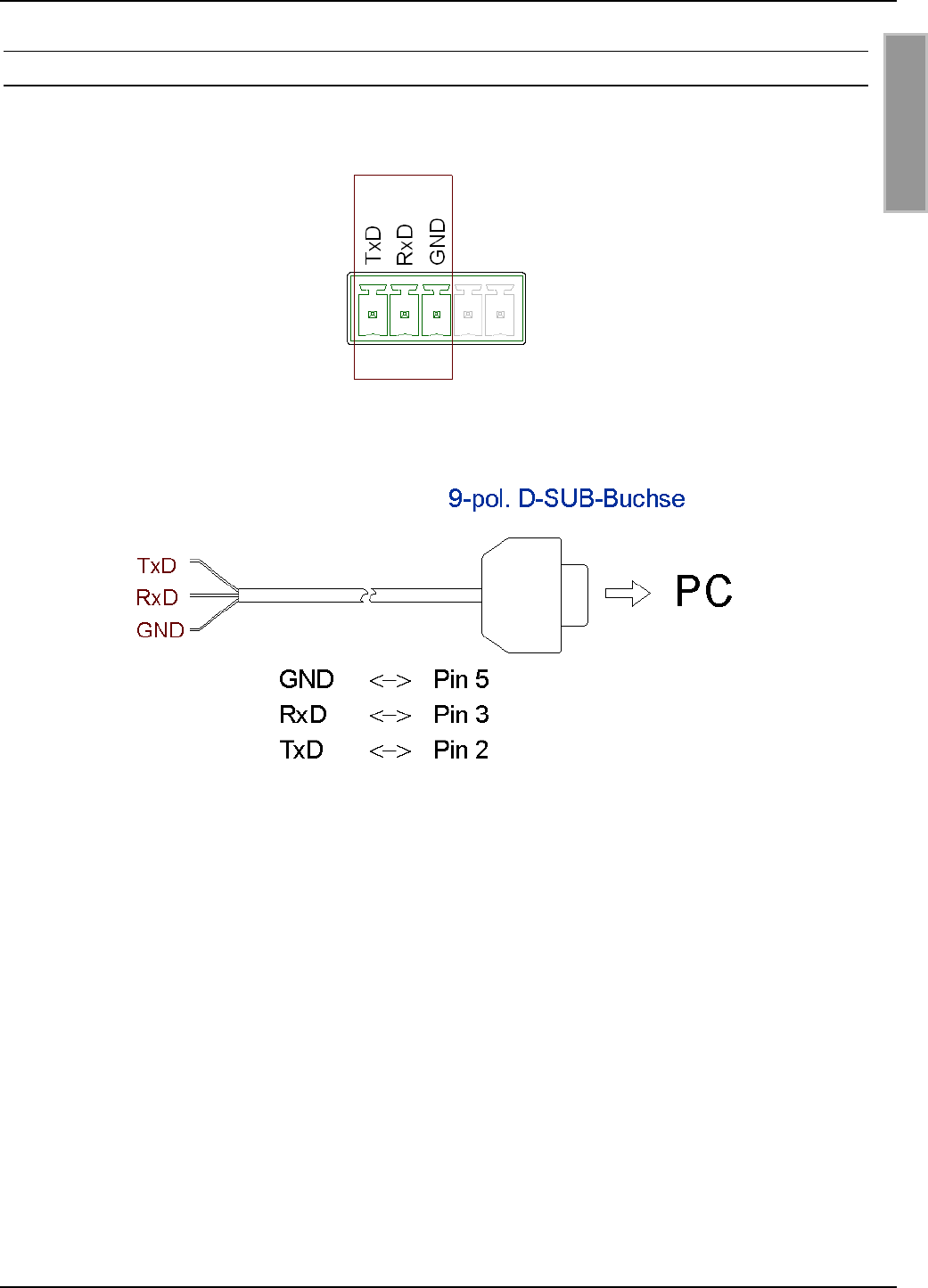
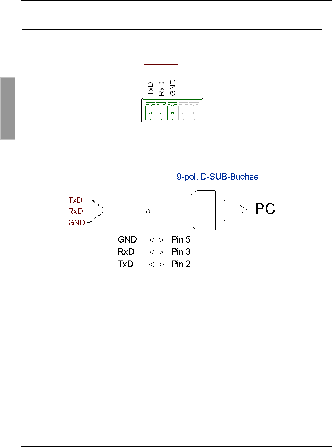
3.2.5 RS232-Schnittstelle X6
Der Anschluss der RS232-Schnittstelle erfolgt über X6. Die Übertragungsparameter können per
Softwareprotokoll konfiguriert werden.
Bild 8 Anschlussbelegung X6 (RS232-Schnittstelle)
Bild 9: Verdrahtungsbeispiel für den Anschluss der RS232-Schnittstelle
OBID i-scan®Montage ID ISC.LRU3000
FEIG ELECTRONIC GmbH Seite 14 von 52 LRU3000 - Manual.doc
D E U T S C H
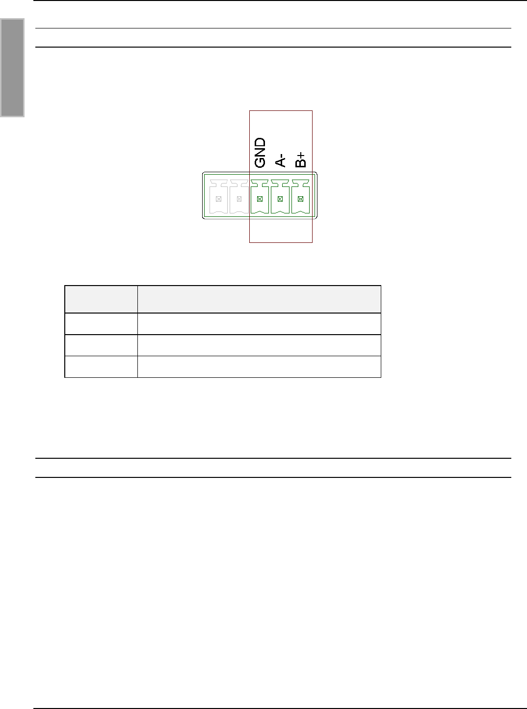
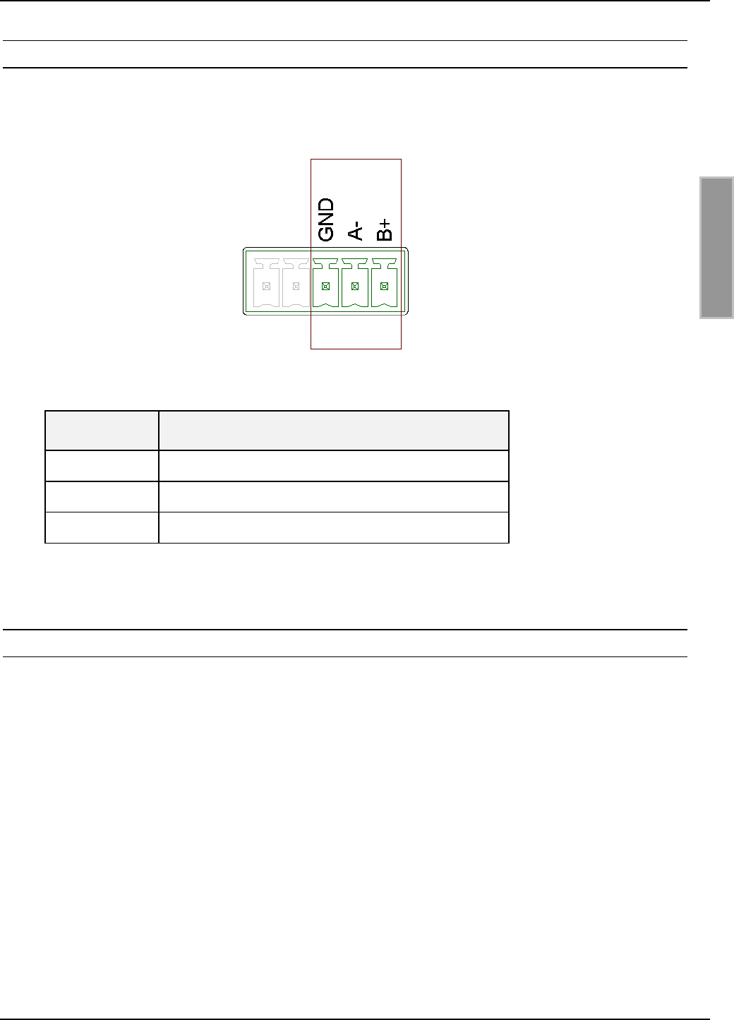
3.2.6 RS485-Schnittstelle X6
Der Anschluss der RS485-Schnittstelle erfolgt ebenfalls über X6.
Die Übertragungsparameter können per Softwareprotokoll konfiguriert werden.
Bild 10 Anschlussbelegung X6 (RS485-Schnittstelle):
Kurzzeichen Beschreibung
GND RS485 – GND
A- RS485 – (A -)
B+ RS485 – (B +)
Tabelle 9: Pinbelegung RS485-Schnittstelle
3.2.6.1 Adresseinstellung RS485 für Busbetrieb
Für den Busbetrieb bietet der Reader die Möglichkeit, die benötigte Busadresse per Software zu
vergeben.
Die Adressvergabe erfolgt über den Host-Rechner. Mit Hilfe der Software können dem Reader die
Adressen "0" bis "254" zugewiesen werden.
Eine evtl. notwendige Terminierung des RS485 Bus kann ebenfalls per Software konfiguriert wer-
den.
Hinweis:
Da alle Reader werksseitig die Adresse 0 eingestellt haben, müssen sie nacheinander ange-
schlossen und konfiguriert werden.
OBID i-scan®Montage ID ISC.LRU3000
FEIG ELECTRONIC GmbH Seite 15 von 52 LRU3000 - Manual.doc
D E U T S C H
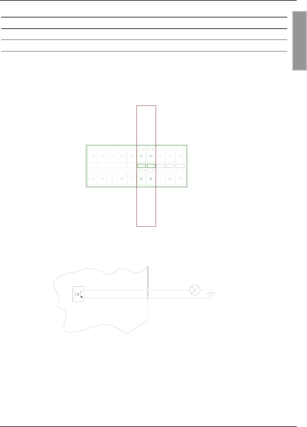
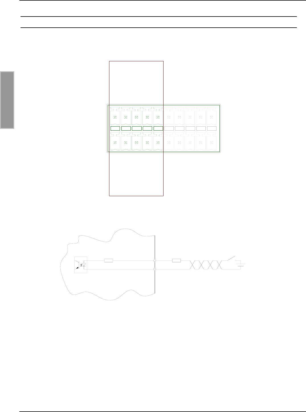
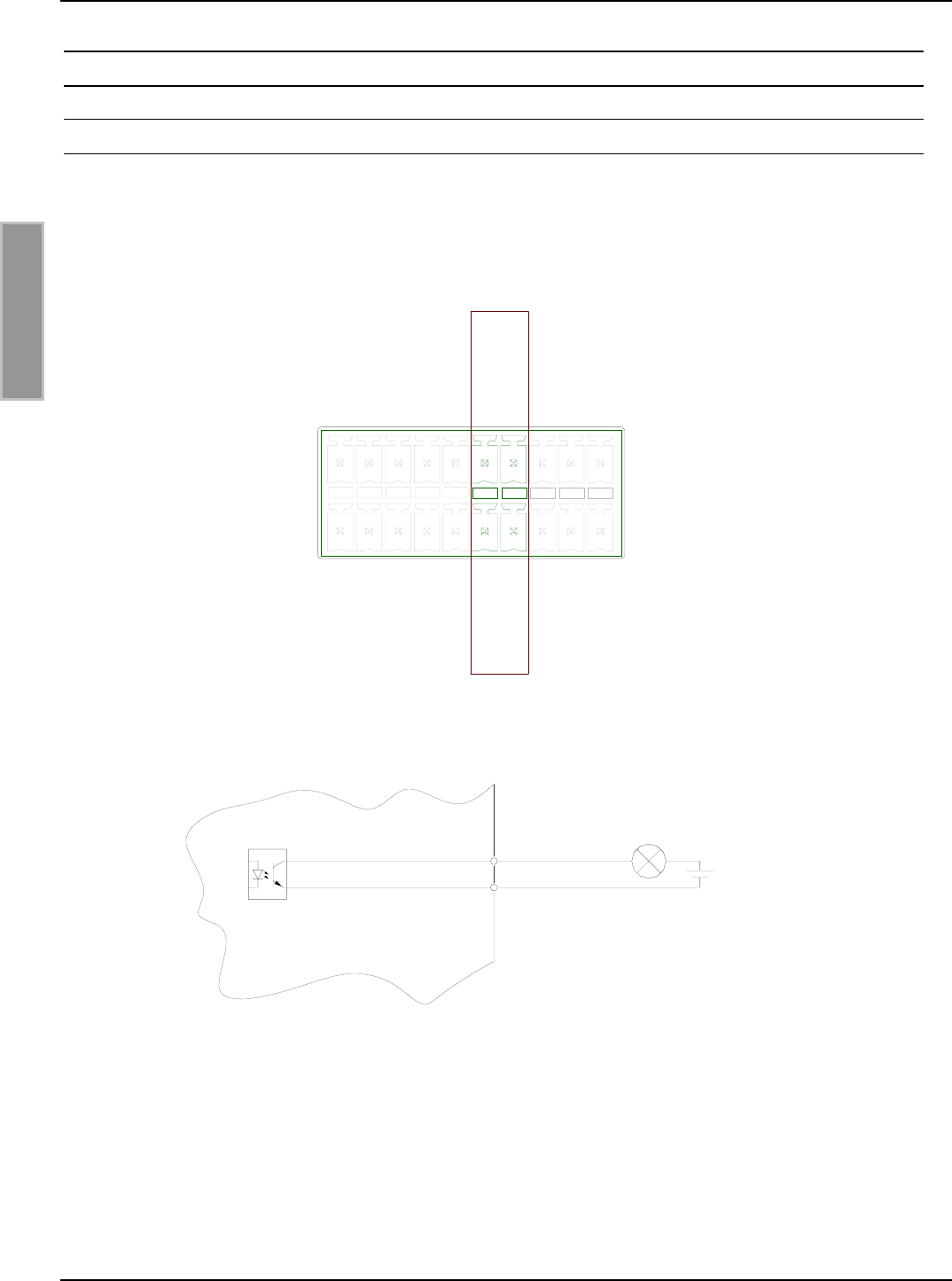
3.3 Digitale Eingänge X5
Die Optokoppler Eingänge an Klemmleiste X5 sind galvanisch von der Reader-Elektronik getrennt
und müssen daher mit einer externen Spannung versorgt werden.
Bild 11 Klemmleiste Digitale Eingänge IN1 – IN5
Bild 12 Interne und mögliche externe Beschaltung der Optokoppler Eingänge
Optokopplereingang (X5 / IN1-5):
Die Eingangs-LED des Optokopplers ist intern mit einem Serienwiderstand von 500 Ω beschaltet.
Bei Versorgungsspannungen größer 10V muss der Eingangsstrom durch einen weiteren externen
Vorwiderstand (siehe Tabelle 10) auf max. 20 mA begrenzt werden.
Tabelle 10 zeigt die benötigten externen Vorwiderstande bei den verschiedenen externen Span-
nungen Uext.
IN1+
IN2+
IN3+
IN4+
IN5+
OUT1-C
OUT2-C
REL1-NO
REL2-NO
REL3-NO
IN1-
IN2-
IN3-
IN4-
IN5-
OUT1-E
OUT2-E
REL1-COM
REL2-COM
REL3-COM
+
IN1..5
Rint Rext
-Uext

OBID i-scan®Montage ID ISC.LRU3000
FEIG ELECTRONIC GmbH Seite 16 von 52 LRU3000 - Manual.doc
D E U T S C H
Externe Spannung Uext Benötigter externer
Vorwiderstand Rext
5 V ... 10 V ---
11 V ... 15 V 270 Ω
16 V ... 20 V 560 Ω
21 V ... 24 V 820 Ω
Tabelle 10: Benötigter externer Vorwiderstand Rext
Hinweise:
• Der Eingang ist für eine maximale Eingangsspannung von 5-10 V DC und einem Ein-
gangsstrom von maximal 20 mA ausgelegt.
• Verpolung oder Überlastung des Eingangs führt zu dessen Zerstörung.
OBID i-scan®Montage ID ISC.LRU3000
FEIG ELECTRONIC GmbH Seite 17 von 52 LRU3000 - Manual.doc
D E U T S C H
3.4 Ausgänge
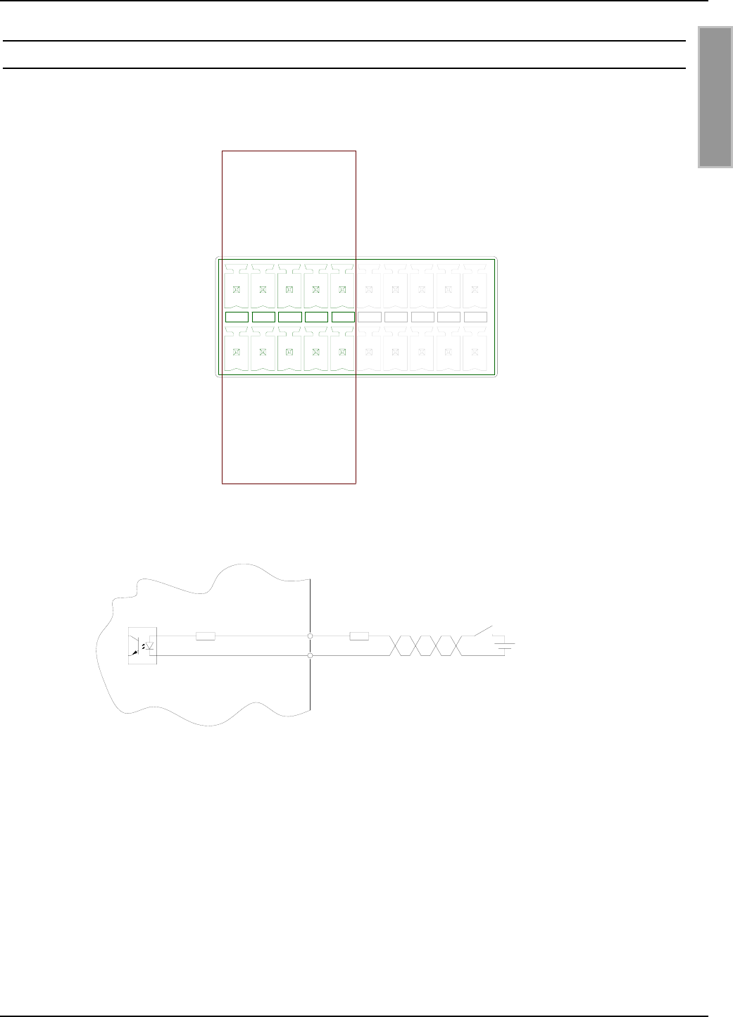
3.4.1 Digitale Ausgänge X5
Optokopplerausgang (X5/1-2):
Der Transistoranschluss, Kollektor und Emitter, des Optokopplerausgangs ist von der Reader-
Elektronik galvanisch getrennt und ohne interne Zusatzbeschaltung an Klemme X5 nach außen
geführt. Der Ausgang muss daher mit einer externen Spannung betrieben werden.
Bild 13 Optokoppler-Ausgänge OUT1-2
Bild 14 Interne und mögliche externe Beschaltung der Optokoppler-Ausgänge OUT1-2
Hinweise:
• Der Ausgang ist für max. 24 V DC / 30 mA ausgelegt.
• Verpolung oder Überlastung des Ausgangs führt zu dessen Zerstörung.
• Der Ausgang ist nur zum Schalten ohmscher Lasten vorgesehen.
OUT1..2 E
C
Uext
IN1+
IN2+
IN3+
IN4+
IN5+
REL1-NO
REL2-NO
REL3-NO
IN1-
IN2-
IN3-
IN4-
IN5-
REL1-COM
REL2-COM
REL3-COM
OUT1-C
OUT2-C
OUT1-E
OUT2-E
OBID i-scan®Montage ID ISC.LRU3000
FEIG ELECTRONIC GmbH Seite 18 von 52 LRU3000 - Manual.doc
D E U T S C H
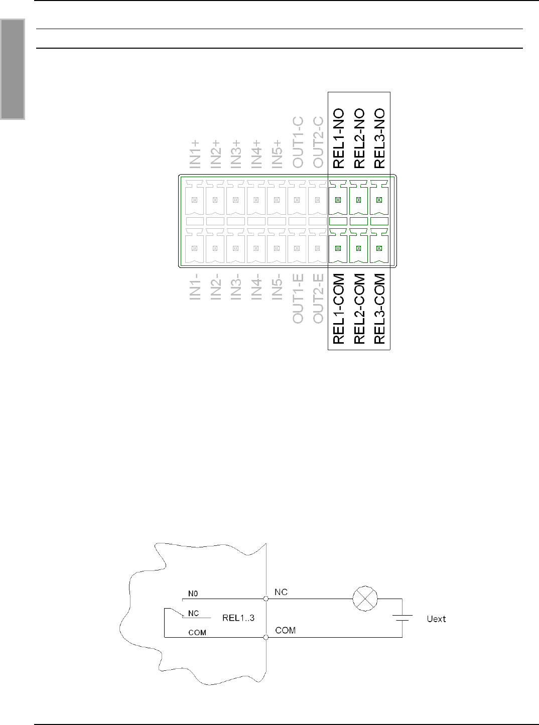
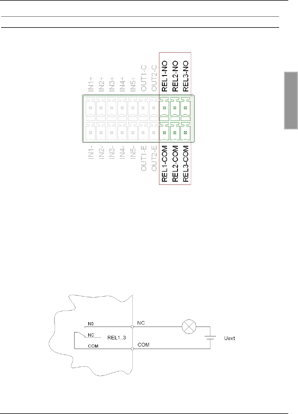
3.4.2 Relais X5
Es stehen 3 Relaisausgänge an der Anschlussklemme X5 als Schließer zur Verfügung.
Bild 15: Pinbelegung Relaisausgänge REL1-3
Hinweise:
• Jeder Relaisausgang ist für max. 24 V DC / 2 A Dauerlast ausgelegt. Der maximale
Schaltstrom darf 1 A nicht überschreiten.
• Der Relaisausgang ist nur zum Schalten ohmscher Lasten vorgesehen. Im Falle einer
induktiven Last sind die Relaiskontakte durch eine externe Schutzbeschaltung zu schüt-
zen.
Bild 16: Externe Beschaltung der Relaisausgänge
OBID i-scan®Montage ID ISC.LRU3000
FEIG ELECTRONIC GmbH Seite 19 von 52 LRU3000 - Manual.doc
D E U T S C H
4 Bedien- und Anzeigeelemente
4.1 Status LEDs
Grün Gelb Rot Beschreibung
AN AUS AN Bootvorgang (ca.10s) nach dem Einschalten
BLINKT AUS AUS Normaler Readerbetrieb (ohne Host Kommunikation)
BLINKT BLINKT AUS Reader empfängt gültiges Protokoll vom Host
BLINKT AUS AN RF Warning [0x84] (ohne Host Kommunikation)
BLINKT
(wechsel-
seitig)
AUS BLINKT
(wechsel-
seitig)
Firmware Activation notwendig [0x17] /
Wrong Firmware [0x18]
BLINKT
(gleichzeitig) AUS BLINKT
(gleichzeitig) RFC Hardware Error [0xF1]
AUS BLINKT
(gleichzeitig)
BLINKT
(gleichzeitig)
Hardware Warning
(ACC EEPROM Error / RFC wird nicht detektiert)
BLINKT AUS BLINKT
(schnell) USB Host Error
Firmware Update:
BLINKT BLINKT BLINKT
(Lauflicht)
Firmware wird vom Host auf den Reader übertragen
(Bitte Reader nicht ausschalten oder Interfacekabel ziehen)
BLINKT BLINKT BLINKT
gleichzeitig
Firmware wird ins EEPROM programmiert.
(Bitte Reader nicht ausschalten oder Interfacekabel ziehen)
ANT 1- 4
RUN
Host
Kommunikation Warning
Input
Output
OBID i-scan®Montage ID ISC.LRU3000
FEIG ELECTRONIC GmbH Seite 20 von 52 LRU3000 - Manual.doc
D E U T S C H
Grün Gelb Rot Beschreibung
Konfigurations-Reset:
BLINKT BLINKT BLINKT
(Lauflicht) Während T1 gedrückt wird bis maximal 5s
AN AN AN Nachdem T1 für 5s gedrückt wurde, Konfigurations-Reset
abgeschlossen.
Input / Output LED (gelb):
Konfigurierbare Anzeige. Kann den Status eines Digitalen Ein- oder Ausgangs an-
zeigen
ANT 1 – 4:
Grün HF Power eingeschaltet
Blau Tag-Detect
ROT Antennen Impedanz Fehler (> 50Ohm oder <50Ohm)
Tabelle 11 Konfiguration der LED’s
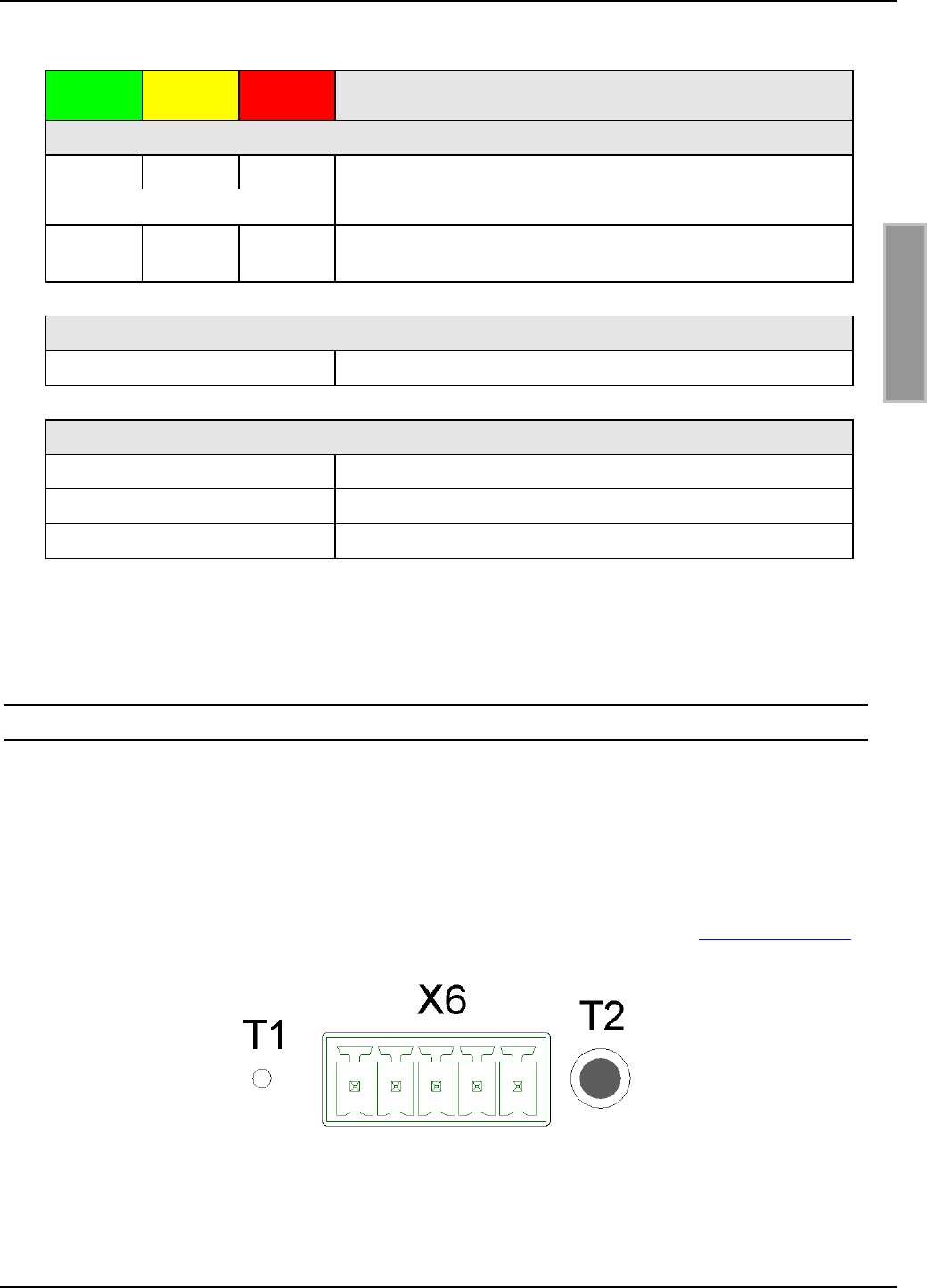
4.2 Reset-Taster
Bild 17 zeigt die Position der Reset Taster T1 und T2.
Rechts neben der Anschlussklemme X6 befindet sich der Taster T2. Mit diesem Taster kann ein
manueller CPU-Reset ausgeführt werden.
Mit dem Taster T1, welcher sich innerhalb des Gehäuses befindet, kann ein kompletter Konfigura-
tions-Reset ausgeführt werden.
Zum Betätigen verwenden Sie bitte eine Büroklammer und drücken die Taste T1 für mindestens
5 s, bis die 3 Status-LED’s (links) dauerhaft aufleuchten.
Bild 17 Position der Reset-Taster T1 und T2
OBID i-scan®Montage ID ISC.LRU3000
FEIG ELECTRONIC GmbH Seite 21 von 52 LRU3000 - Manual.doc
D E U T S C H
4.3 Reader Leistungseinstellung
Um hohe Lesereichweiten zu erreichen ist es notwendig, die Ausgangsleistung des Readers auf
die maximal erlaubte Ausgangsleistung einzustellen. Das ist abhängig von dem verwendeten Rea-
der Typ (EU / FCC) und der Zulassung in dem jeweiligen Land, in dem der Reader verwendet wird.
4.3.1 EU-Reader (EN 302 208)
Nach der Norm EN 302 208 ist eine maximale abgestrahlte Leistung von 2 W e.r.p. (Effective Ra-
diated Power) erlaubt. Die im Reader einzustellende Leistung Pout ist abhängig von der Kabel-
dämpfung und dem Antennengewinn in dBi. Bei Verwendung einer zirkular polarisierte Antenne ist
der Gewinn ([G] = dBic) um 3 dB zu reduzieren. Bei einer linearen Antenne ist der maximale linea-
re Gewinn ([G]= dBi) anzusetzen.
POut = Pe.r.p. - Antennengewinn + Kabeldämpfung + 2,1dB**
** Korrekturfaktor zur Umrechnung der abgestrahlten Leistung von e.r.p in e.i.r.p
Für die Berechnung der am Reader einzustellenden Sendeleistung steht eine „Calc-RF-Power.xls“
Excel Datei zur Verfügung. Verfügbar bei Feig Electronic GmbH.
Beispiel:
Tabelle 12: Berechnung der maximalen zulässigen Ausgangsleistung des Readers
** lineare Antenne = „0“, zirkulare Antennen = „1“
In Tabelle 12: Berechnung der maximalen zulässigen Ausgangsleistung des Readers wird die Be-
rechnung der erlaubten Ausgangsleistung bei Verwendung der Antenne ANT.U600/270 -EU und
einem 6m langen Belden H155 Kabel dargestellt.

OBID i-scan®Montage ID ISC.LRU3000
FEIG ELECTRONIC GmbH Seite 22 von 52 LRU3000 - Manual.doc
D E U T S C H
4.3.2 FCC-Reader
Entsprechend der FCC Zulassung, Title 47, Part15 ist an der SMA Buchse des Readers eine ma-
ximale Ausgangsleistung von 1 W (30 dBm) zulässig. Die von der Antenne abgestrahlte Leistung
darf einen Wert von 4 W e.i.r.p nicht überschreiten.
Daraus ergibt sich für linear polarisierte Antennen, deren Gewinn kleiner ist als 6 dBi, bzw. zirkular
polarisierte Antennen mit einem Gewinn kleiner 9 dBic, dass im Reader immer eine maximale
Ausgangsleitung von 1 Watt konfiguriert werden darf.
Antennengewinn < 6 dBi →POut = 1 W
Dies trifft zu bei der Verwendung der beiden FEIG Standardantennen ANT.U170/170 –FCC
(4 dBic) und ANT.U270/270 –FCC (8,7 dBic).
Werden Antennen mit einem größeren Gewinn als 6dBi (9 dBic) verwendet, so müssen bei der
Berechnung der Ausgangsleistung des Readers der Antennengewinn und die Kabeldämpfung mit
berücksichtigt werden. Wird eine zirkulare Antenne verwendet, so können 3dB von dem Antenne-
gewinn [G]= dBic abgezogen werden. Dies trifft zu bei Verwendung der FEIG Standardantenne
ANT.U600/270. Bei solch einer Konstellation ergibt sich folgende Berechnung der Aus-
gansgleistung des Readers:
POut = 36 dBm (4 W e.i.r.p) – Antennengain (in dBi) + Kabeldämpfung (in dB)
POut = 36 dBm (4 W e.i.r.p) – Antennengain (in dBic) – 3 dB + Kabeldämpfung (in dB)
Der Antennengewinn der zirkular Polarisierten Antenne ANT.U600/270 beträgt 10,5 dBic. Dies
entspricht einem Gewinn einer linearen Antenne von 7,5 dBi (10,5 dBic – 3 dB).
Beispiel 1:
Antenne ANT.U600/270 mit 2 m Belden H155 Koaxialkabel:
Pout= 36 dBm – 10,5 dBic + 3 dB + 0,6 dB
Pout= 36 dBm – 7,5 dBi + 0,6 dB
Pout= 29,1 dBm
Reader Configuration = 0,8 Watt

OBID i-scan®Montage ID ISC.LRU3000
FEIG ELECTRONIC GmbH Seite 23 von 52 LRU3000 - Manual.doc
D E U T S C H
Beispiel 2:
Antenne ANT.U600/270 mit 6m Belden H155 Koaxialkabel:
Pout= 36 dBm – 10,5 dBic + 3 dB + 1,8 dB
Pout= 36 dBm – 7,5 dBi + 1,8 dB
Pout= 30,3 dBm
Reader Configuration = 1,0 Watt
Aus Beispiel 2 lässt sich ableiten, dass bei der Verwendung der ANT.U600/270 eine Anpassung
der Ausgangsleistung nur bei Verwendung von Kabellängen kleiner 6m notwendig wird.

OBID i-scan®Montage ID ISC.LRU3000
FEIG ELECTRONIC GmbH Seite 24 von 52 LRU3000 - Manual.doc
D E U T S C H
5 Funkzulassungen
5.1 Europa (CE)
Die Funkanlage entspricht, bei bestimmungsgemäßer Verwendung den grundlegenden Anforde-
rungen des Artikels 3 und den übrigen einschlägigen Bestimmungen der R&TTE Richtlinie
1999/5/E6 vom März 99.
Equipment Classification gemäß ETSI EN 301 489: Class 2

OBID i-scan®Montage ID ISC.LRU3000
FEIG ELECTRONIC GmbH Seite 25 von 52 LRU3000 - Manual.doc
D E U T S C H
5.2 USA (FCC)
FCC ID: PJMLRU3000
This device complies with Part 15 of the FCC Rules. Operation is subject to the following
two conditions:
(1) this device may not cause harmful interference, and
(2) this device must accept any interference received, including interference that may
cause undesired operation.
NOTICE:
Changes or modifications made to this equipment not expressly approved by
FEIG ELECTRONIC GmbH may void the FCC authorization to operate this equipment.
NOTE: This equipment has been tested and found to comply with the limits for a Class B digital
device, pursuant to Part 15 of the FCC Rules. These limits are designed to provide reasonable
protection against harmful interference in a residential installation. This equipment generates, uses
and can radiate radio frequency energy and, if not installed and used in accordance with the
instructions, may cause harmful interference to radio communications. However, there is no
guarantee that interference will not occur in a particular installation. If this equipment does cause
harmful interference to radio or television reception, which can be determined by turning the
equipment off and on, the user is encouraged to try to correct the interference by one or more of
the following measures:
- Reorient or relocate the receiving antenna.
- Increase the separation between the equipment and receiver.
- Connect the equipment into an outlet on a circuit different from that to which the receiver is
connected
- Consult the dealer or an experienced radio/TV technician for help.
To reduce potential radio interference to other users, the antenna type and its gain should be so
chosen that the equivalent isotropically radiated power (EIRP) is not more than that permitted for
successful communication.
This device has been designed to operate with the antennas listed below, and having a maximum
gain of 10.5 dBic. Antennas not included in this list or having a gain greater than 10.5 dBic are
strictly prohibited for use with this device. The required antenna impedance is 50 ohms. Lists of
Antennas:
ID.ISC.ANT.U250/250-FCC, ID.ISC.ANT.U170/170-FCC, ID ISC.ANT.U270/270-FCC,
ID ISC.ANT.U600/270-FCC
5.3 Canada compliance statement (IC: 6633A-LRU3000)
Operation is subject to the following two conditions:
(1) this device may not cause interference, and
(2) this device must accept any interference, including interference that may cause undesired op-
eration of the device.
Usually this is followed by the following RSS caution:
Any changes or modifications not expressly approved by the party responsible for compliance
could void the user's authority to operate this equipment.

OBID i-scan®Montage ID ISC.LRU3000
FEIG ELECTRONIC GmbH Seite 26 von 52 LRU3000 - Manual.doc
D E U T S C H
6 Technische Daten
Mechanische Daten
• Gehäuse Aluminium, pulverbeschichtet
• Abmessungen ( B x H x T ) 261,3 x 157,3 x 68 mm³
• Gewicht 2,0 kg
• Schutzart IP 53 (mit Schutzkappe IP64)
• Farbe RAL 9003 Signalweiß
Elektrische Daten
Spannungsversorgung
alternativ:
24 V DC ± 5 % (Noise Ripple : max. 150 mV)
PoE (Power over Ethernet) (mind. 42,5 V DC)
(bis 1Watt Ausgangsleistung)
• Leistungsaufnahme max. 35 VA
• Betriebsfrequenzen:
EU Reader
FCC Reader
865,7 – 867,5MHz (4 Channel Plan))
902-928MHz (FCC CFR 47 Part 15.247)
• Ausgangsleistung 300 mW – 4 W konfigurierbar
(maximal 1 W bei Power over Ethernet)
• RF-Diagnose RF-Kanalüberwachung, Antennen SWR Überwa-
chung, interne Überhitzungskontrolle
• Antennenanschlüsse
– 4 x gemultiplext 4 x SMA Buchse (50Ω)
• Ausgänge:
- 2 Optokoppler
- 3 Relais ( Schliesser))
24 V DC / 30 mA (galvanisch getrennt)
24 V DC / 1 A (Schaltstrom), (2A Dauerlast)
• Eingänge
- 5 Optokoppler max. 5-10 V DC / 20 mA
• Schnittstellen - RS232
– RS485
– USB (full speed)
– Ethernet (TCP/IP)

OBID i-scan®Montage ID ISC.LRU3000
FEIG ELECTRONIC GmbH Seite 27 von 52 LRU3000 - Manual.doc
D E U T S C H
Funktionsmerkmale
• Protokoll Modi - FEIG ISO Host Mode
– Buffer Reader Mode (Data Filtering and
- Notification Mode buffering)
– Scan Mode
• Unterstützte Transponder - EPC class 1 Gen 2
– EM4222 / 4444 (optional)
– 18000-6-B/-C (optional)
• Signalgeber optisch 8 LEDs zur Diagnose des Betriebszustandes
• Betriebssystem Linux (64MB RAM, 256MB Flash)
• Sonstiges Antikollisionsfunktion, Echtzeituhr, RSSI
Umgebungsbedingungen
• Temperaturbereich
– Betrieb
– Lagerung
-25°C bis +50°C
-25°C bis +85°C
• Rel. Luftfeuchtigkeit 5% -95% (nicht betauend)
• Vibration EN60068-2-6
10 Hz bis 150 Hz : 0,075 mm / 1 g
• Schock EN60068-2-27
Beschleunigung : 30 g
Angewendete Normen
- Zulassung Funk
-Europa
-USA
EN 302 208
FCC 47 CFR Part 15
• EMV EN 301 489
• Sicherheit
- Niederspannung
- Human Exposure
EN 60950
EN 50364

OBID i-scan®Installation ID ISC.LRU3000
FEIG ELECTRONIC GmbH Page 28 of 52 LRU3000 - Manual.doc
E N G L I S H
Note
© Copyright 2009 by
FEIG ELECTRONIC GmbH
Lange Strasse 4
D-35781 Weilburg-Waldhausen
Tel.: +49 6471 3109-0
http://www.feig.de
With the edition of this document, all previous editions become void. Indications made in this manual may be
changed without previous notice.
Copying of this document, and giving it to others and the use or communication of the contents thereof are
forbidden without express authority. Offenders are liable to the payment of damages. All rights are reserved
in the event of the grant of a patent or the registration of a utility model or design.
Composition of the information in this manual has been done to the best of our knowledge. FEIG
ELECTRONIC GmbH does not guarantee the correctness and completeness of the details given in this
manual and may not be held liable for damages ensuing from incorrect or incomplete information. Since,
despite all our efforts, errors may not be completely avoided, we are always grateful for your useful tips.
The instructions given in this manual are based on advantageous boundary conditions. FEIG ELECTRONIC
GmbH does not give any guarantee promise for perfect function in cross environments and does not give
any guaranty for the functionality of the complete system which incorporates the subject of this document.
FEIG ELECTRONIC call explicit attention that devices which are subject of this document are not designed
with components and testing methods for a level of reliability suitable for use in or in connection with surgical
implants or as critical components in any life support systems whose failure to perform can reasonably be
expected to cause significant injury to a human. To avoid damage, injury, or death, the user or application
designer must take reasonably prudent steps to protect against system failures.
Use Exclusion in Transportation Market: Devices which are subject of this document may NOT be sold,
used, leased, offer for sale, or otherwise transferred, exported, and imported by anyone in the Transportation
Market. “Transportation Market” means (i) Electronic Toll and Traffic Management (ETTM), (ii) Public Sector
Vehicle Registration, Inspection and Licensing Programs, (iii) Railroad Locomotive and Wagon tracking, (iv)
airport based ground transportation management systems (GTMS) and taxi dispatch, (v) revenue based
parking, and (vi) vehicle initiated mobile payment applications, where the RFID sticker/tag is initially attached
to the vehicle but not incorporated at the point of vehicle manufacture.
FEIG ELECTRONIC GmbH assumes no responsibility for the use of any information contained in this
manual and makes no representation that they free of patent infringement. FEIG ELECTRONIC GmbH does
not convey any license under its patent rights nor the rights of others.
OBID® and OBID i-scan® are registered trademarks of FEIG ELECTRONIC GmbH.

OBID i-scan®Installation ID ISC.LRU3000
FEIG ELECTRONIC GmbH Page 29 of 52 LRU3000 - Manual.doc
E N G L I S H
Contents
7 Performance Features of Reader Family ID ISC.LRU3000 31
7.1 Performance features..................................................................................................31
7.2 Available Reader types ...............................................................................................31
7.3 Available Accessories ................................................................................................31
8 Installation 32
9 Terminals 33
9.1 Antenna connection....................................................................................................34
9.1.1 Power supply connection on X1 ....................................................................................34
9.2 Interfaces .....................................................................................................................35
9.2.1 Power Supply via PoE (Power over Ethernet) on X2 ....................................................35
9.2.2 Ethernet-Interface on X2 (10/100Tbase).......................................................................36
9.2.3 USB – Interface X3 (Host Communication)...................................................................37
9.2.4 USB – Interface X4 (WLAN)..........................................................................................37
9.2.5 RS232-Interface X6.......................................................................................................38
9.2.6 RS485-Interface on X6..................................................................................................39
9.3 Digital Inputs X5 ..........................................................................................................40
9.4 Outputs.........................................................................................................................42
9.4.1 Digital Outputs X5 .........................................................................................................42
9.4.2 Relays X5 ......................................................................................................................43
10 Operating and Display Elements 44
10.1 Status LEDs .................................................................................................................44
10.2 Reset-Push Button ......................................................................................................45
10.3 Reader Power adjustment ..........................................................................................46
10.3.1 EU-Reader (EN302 208) ...............................................................................................46
10.3.2 FCC-Reader ..................................................................................................................47
11 Radio Approvals 49
11.1.1 Europe (CE) ..................................................................................................................49
11.2 USA (FCC) ...................................................................Fehler! Textmarke nicht definiert.
12 Technical Data 51

OBID i-scan®Installation ID ISC.LRU3000
FEIG ELECTRONIC GmbH Page 30 of 52 LRU3000 - Manual.doc
E N G L I S H
Safety Instructions / Warning - Read before start-up !
• The device may only be used for the purpose intended by the manufacturer
• When installing the device in areas covered under FCC 47 CFR Part 15 a minimum separation
of 25 cm between antenna and the human body must be maintained.
• The operation manual should be kept readily available at all times for each user.
• Unauthorized changes and the use of spare parts and additional devices which have not been
sold or recommended by the manufacturer may cause fire, electric shocks or injuries. Such
unauthorized measures shall exclude the manufacturer from any liability.
• The liability-prescriptions of the manufacturer in the issue valid at the time of purchase are valid
for the device. The manufacturer shall not be held legally responsible for inaccuracies, errors,
or omissions in the manual or automatically set parameters for a device or for an incorrect
application of a device.
• Repairs may only be undertaken by the manufacturer.
• Installation, operation, and maintenance procedures should only be carried out by qualified
personnel.
• Use of the device and its installation must be in accordance with national legal requirements
and local electrical codes .
• When working on devices the valid safety regulations must be observed.
• Special advice for wearers of cardiac pacemakers:
Although this device doesn't exceed the valid limits for electromagnetic fields you should keep
a minimum distance of 25 cm between the device and your cardiac pacemaker and not stay in
the immediate proximity of the device’s antenna for any length of time.
OBID i-scan®Installation ID ISC.LRU3000
FEIG ELECTRONIC GmbH Page 31 of 52 LRU3000 - Manual.doc
E N G L I S H
7 Performance Features of Reader Family ID ISC.LRU3000
7.1 Performance features
The Reader has been developed for reading passive data carriers, so-called „Smart Labels“, using
an operating frequency in the UHF range.
7.2 Available Reader types
The following Readers are available:
Reader type Description
ID ISC.LRU3500-EU Device version for Europe with PoE
ID ISC.LRU3000-EU Device version for Europe without PoE
ID ISC.LRU3500-FCC Device version for USA with PoE
ID ISC.LRU3000-FCC Device version for USA without PoE
Table 1: Reader types
7.3 Available Accessories
The following optional accessories are currently available:
Reader type Description
ID ISC.LRU3000-PGM
Protection cap for IP 64
Table 2 Optional reader accessorie
OBID i-scan®Installation ID ISC.LRU3000
FEIG ELECTRONIC GmbH Page 32 of 52 LRU3000 - Manual.doc
E N G L I S H
8 Installation
The Reader is designed for wall-mount, including outdoors. Holes for mounting on a wall are
provided in the housing.
It is not necessary to open the reader housing.
261,3 (10.29)
157,3 (6.19)
241,7 (9.52)
34 (1.34)5,5 (1.00)
68 (2.68)
Fig. 1 Installation drawing
OBID i-scan®Installation ID ISC.LRU3000
FEIG ELECTRONIC GmbH Page 33 of 52 LRU3000 - Manual.doc
E N G L I S H
9 Terminals
On the lower side of the reader housing the different cable connectors are positioned. Fig. 2 shows
the arrangement of the connectors and Table 3s shows which connection for the different cables
are used for.
Table 4 shows the available push buttons.
X2 X3 X4
X5
X6
T1 T2
X1 ANT1 ANT2 ANT3 ANT4
Fig. 2: Connection Overview
Connector Description
ANT 1-4 Connection of the external antennas (Impedance 50Ω)
X1 Power supply 24VDC +-5%
X2 10/100Tbase network connection with RJ-45 (with PoE)
X3 USB interface for host communication
X4 USB interface for WLAN-Sticks
X5 Digital input and output and relay output
X6 RS232 / 485 interface
Table 3 Connection terminals
Push
button
Description
T1 Internal push button for complete configuration reset
T2 External push button for CPU-Reset
Table 4 Push button function
OBID i-scan®Installation ID ISC.LRU3000
FEIG ELECTRONIC GmbH Page 34 of 52 LRU3000 - Manual.doc
E N G L I S H
9.1 Antenna connection
The external SMA antenna connectors are positioned on the lower side of the reader.
The maximum tightening torque for the SMA sockets is 0.45 Nm (4.0 lbf in).
Caution:
Exceeding the tightening torque will destroy the plug.
Terminal Description
ANT 1-4 Connection for external antennas (input impedance 50Ω)
Table 5: External antenna connection
Fig. 3 External antenna connection ANT1-4 and X1 for the power supply
9.1.1 Power supply connection on X1
The supply voltage of 24 V DC has to be connected to Terminal X1.
Terminal Abbreviation Description
X1 / Pin 1 VDC Vcc – supply voltage 24VDC +-5%
X1 / Pin 2 GND Ground – supply voltage
Table 6: Pin assignment for power supply
Fig. 4: Connection for the power supply
ANT1 ANT2 ANT3 ANT4
X1
OBID i-scan®Installation ID ISC.LRU3000
FEIG ELECTRONIC GmbH Page 35 of 52 LRU3000 - Manual.doc
E N G L I S H
9.2 Interfaces
9.2.1 Power Supply via PoE (Power over Ethernet) on X2
Optional the reader can be powered via the LAN connector on X2 with the use of a PoE „Power
over Ethernet“ power supply according to IEEE802.3at*, Class4 (30/25,5Watt). The DC supply can
be achieved via the free pin’s 4,5 and 7,8 (Midspan-Power). Also a “Phantom Powering” (Inline-
Power) via the signal pin’s 1,2,3,and 6 is possible.
Fig. 5 LAN and PoE connection
Note:
• Take care if PoE is used the maximum reader output power of the reader must be limited
to 1Watt.
• It must be ensured that the reader is supplied with 42,5 V DC (48 V DC – cable losses) at
least.
Depending on the cable cross-section the following cable distances can be used.
cable cross-section (CAT5...7) Maximum cable length for PoE
0,4mm ≈ 30m
0,6mm ≈ 70m
Table 7 Maximum cable length if PoE is used.
* For detailed technical information regarding the 802.3at standard, please refer to the most
recent edition of the corresponding IEEE specification.

OBID i-scan®Installation ID ISC.LRU3000
FEIG ELECTRONIC GmbH Page 36 of 52 LRU3000 - Manual.doc
E N G L I S H
9.2.2 Ethernet-Interface on X2 (10/100Tbase)
The Reader has an integrated 10 / 100 base-T network port for an RJ-45. Connection is made on
X2 and has an automatic “Crossover Detection” according to the 100BASE-T Standard.
With structured cabling CAT 5 cables should be used. This ensures a reliable operation at 10 Mbps
or 100 Mbps.
The prerequisite for using TCP/IP protocol is that each device has a unique address on the net-
work. All Readers have a factory set IP address.
Network Address
IP-Adresse 192.168.10.10
Subnet-Mask 255.255.255.0
Port 10001
DHCP OFF
Table 8 Standard factory configuration of the Ethernet connection
OBID i-scan®Installation ID ISC.LRU3000
FEIG ELECTRONIC GmbH Page 37 of 52 LRU3000 - Manual.doc
E N G L I S H
9.2.3 USB – Interface X3 (Host Communication)
The USB socket on the board is terminal X3. The pinout is standardized. The data rate is reduced
to 12 Mbit (USB full speed). A standard USB-cable can be used.
Fig. 6 USB-Interface for host communication
Note:
The length of the USB-cable can be a max. of 5m (20 inch). It is not allowed to use longer
cables.
9.2.4 USB – Interface X4 (WLAN)
The USB-Port X4 can be used for a standard WLAN-USB-Stick
Fig. 7 USB-Interface for external WLAN interface
Note
It is possible to use standard WLAN-USB-Sticks. It must be ensured that this stick contains
a „Ralink“ Chipsatz „RT2500 USB“ or „RT73“.
For example the following WLAN-Stick are successfully tested with the ID ISC.LRU3000:
Manufacturer Description Model
Gigabyte Air Cruiser G USB Adapter GN-WBKG
ASUS USB2.0 WLAN Adapter WL-167G
Linksys Compact Wireless-G USB Adapter WUSB54GC
Table 9 Successfully tested WLAN Sticks.
OBID i-scan®Installation ID ISC.LRU3000
FEIG ELECTRONIC GmbH Page 38 of 52 LRU3000 - Manual.doc
E N G L I S H
9.2.5 RS232-Interface X6
The RS232 interface is connected on X6.
The transmission parameters can be configured by means of software protocol.
Fig. 8 RS232 interface pin-outs on X6
Fig. 9: Wiring example for connecting the RS232 interface RS485-Schnittstelle X6
OBID i-scan®Installation ID ISC.LRU3000
FEIG ELECTRONIC GmbH Page 39 of 52 LRU3000 - Manual.doc
E N G L I S H
9.2.6 RS485-Interface on X6
The connection of the RS485 interface take place via the X6 connector as well.
The interface parameter can be configured via software protocols.
Fig. 10 RS485 interface pin-outs on X6 (RS485-Interface):
Abbreviation Description
GND RS485 – GND
A- RS485 – (A -)
B+ RS485 – (B +)
Table 10: RS485 interface pin-outs
9.2.6.1 Address assignment of RS485 for bus operation
For bus operation the Reader can be assigned the required bus address via software.
The address is assigned by the host computer. The software is used to assign addresses “0”
through “254” to the Reader.
Note:
Since all Readers are factory set with address „0“, they must be connected and configured
one after the other.
OBID i-scan®Installation ID ISC.LRU3000
FEIG ELECTRONIC GmbH Page 40 of 52 LRU3000 - Manual.doc
E N G L I S H
9.3 Digital Inputs X5
The optocouplers on Terminal X5 are galvanically isolated from the Reader electronics and must
therefore be externally supplied.
Fig. 11 Optocoupler pin-outs IN1 – IN5
Fig. 12 Internal and possible external wiring of the optocouplers
Optocoupler input (X5/1-5):
The input LED associated with the optocoupler is connected internally to a series resistor of 500 Ω.
For supply voltages of greater than 10V the input current must be limited to max. 20 mA by means
of an additional series resistor (see Table 11).
Table 11 shows the necessary external resistors for various external voltages Uext.
IN1+
IN2+
IN3+
IN4+
IN5+
OUT1-C
OUT2-C
REL1-NO
REL2-NO
REL3-NO
IN1-
IN2-
IN3-
IN4-
IN5-
OUT1-E
OUT2-E
REL1-COM
REL2-COM
REL3-COM
+
IN1..5
Rint Rext
-Uext

OBID i-scan®Installation ID ISC.LRU3000
FEIG ELECTRONIC GmbH Page 41 of 52 LRU3000 - Manual.doc
E N G L I S H
External voltage Uext Required external series
resistor Rext
5 V ... 10 V ---
11 V ... 15 V 270 Ω
16 V ... 20 V 560 Ω
21 V ... 24 V 820 Ω
Table 11: Required external series resistor Rext
Notes:
• The input is configured for a maximum input voltage of 5-10 V DC and an input current
of max. 20 mA.
• Polarity reversal or overload on the input will destroy it.
OBID i-scan®Installation ID ISC.LRU3000
FEIG ELECTRONIC GmbH Page 42 of 52 LRU3000 - Manual.doc
E N G L I S H
9.4 Outputs
9.4.1 Digital Outputs X5
Optocoupler output (X5/1-2):
The transistor connections, collector and emitter, of the optocoupler output are galvanically isolated
from the Reader electronics and are carried to the outside without any internal ancillary circuitry on
Terminal X5. The output must therefore be powered by an external power supply.
Fig. 13 Optocoupler -Outputs OUT1-2
Fig. 14 Internal and possible external wiring of the optocoupler-outputs OUT1-2
Note:
• The output is configured for max. 24 V DC / 30 mA.
• Polarity reversal or overload on the output will destroy it.
• The output is intended for switching resistive loads only.
OUT1..2 E
C
Uext
IN1+
IN2+
IN3+
IN4+
IN5+
REL1-NO
REL2-NO
REL3-NO
IN1-
IN2-
IN3-
IN4-
IN5-
REL1-COM
REL2-COM
REL3-COM
OUT1-C
OUT2-C
OUT1-E
OUT2-E
OBID i-scan®Installation ID ISC.LRU3000
FEIG ELECTRONIC GmbH Page 43 of 52 LRU3000 - Manual.doc
E N G L I S H
9.4.2 Relays X5
There are 3 relay outputs available on connector X5.
Fig. 15: Relay output pin-outs REL1-3
Notes:
• The relay output is configured for max. 24 V DC / 2 A constant load. The switching cur-
rent must not exceed 1A.
• The relay output is intended for switching resistive loads only. If an inductive load is
connected, the relay contacts must be protected by means of an external protection cir-
cuit.
Fig. 16: Internal and possible external wiring of the relay output
OBID i-scan®Installation ID ISC.LRU3000
FEIG ELECTRONIC GmbH Page 44 of 52 LRU3000 - Manual.doc
E N G L I S H
10 Operating and Display Elements
10.1 Status LEDs
Green Yellow Red Description
ON OFF ON Boot sequence (ca.10s) after power on
FLASH OFF OFF Normal Reader operation (without Host communication)
FLASH BLINKT OFF Reader receives a valid protocol from host
FLASH OFF ON RF Warning [0x84] (without host communication)
FLASH
(alternat-
ing)
OFF FLASH
(alternat-
ing)
Firmware Activation necessary [0x17] /
Wrong Firmware [0x18]
FLASH
(synchro-
nous)
OFF FLASH
(synchro-
nous)
RFC Hardware Error [0xF1]
OFF FLASH
(synchro-
nous)
FLASH
(synchro-
nous)
Hardware Warning
(ACC EEPROM Error / RFC not detected)
FLASH OFF FLASH
(fast) USB Host Error
Firmware Update:
FLASH FLASH FLASH
(light in sequence)
Firmware transfer from host to reader
(Please do not switch off the reader or disconnect the interface cable)
FLASH FLASH FLASH
synchronous
Firmware flash into EEPROM.
(Please do not switch off the reader or disconnect the interface cable)
ANT 1- 4
RUN
Host
Communication Warning
Input
Output
OBID i-scan®Installation ID ISC.LRU3000
FEIG ELECTRONIC GmbH Page 45 of 52 LRU3000 - Manual.doc
E N G L I S H
Green Yellow Red Description
Configurations-Reset:
FLASH FLASH FLASH
(light in sequence) While T1 is pushed and hold for maximal 5s
ON ON ON After T1 has been pushed and hold for 5s. Configuration
Reset has been finished.
Input / Output LED (yellow):
Configurable LED. Can display the status of a digital input or output
ANT 1 – 4:
Green HF Power switched on
Blue Tag-Detect
Red Antenna impedance error (> 50Ohm or <50Ohm)
Table 12 Configuration of the status LED’s
10.2 Reset-Push Button
Fig. 17 shows the position of the reset push button’s T1 and T2.
At the right side of the connector X6 the push button T2 is positioned. With this push button a CPU-
Reset can be performed.
With the push button T1 within the reader housing on left side of X3 a complete configuration reset
can be performed. For performing a reset you should use a paper clip and push the button T1 for
at least 5 s until the 3 status LED’s (left side) are switched on continuously, see 10.1.Status LEDs
Fig. 17 Position of the reset-switches T1 and T2
OBID i-scan®Installation ID ISC.LRU3000
FEIG ELECTRONIC GmbH Page 46 of 52 LRU3000 - Manual.doc
E N G L I S H
10.3 Reader Power adjustment
To achieve the optimum reading performance it is necessary to set the reader output power to the
highest allowed value. This depends on the used reader type (EU / FCC) and the regulation in the
country were the reader is used.
10.3.1 EU-Reader (EN302 208)
According to the standard EN302 208 the maximum radiated power is 2 W e.r.p. (Effective Radi-
ated Power) in countries of the European Union.
The in the reader configured output power Pout depends on the antenna gain in dBi and the at-
tenuation of the antenna cable. If a circular polarized antenna is used the antenna gain [dBic] can
be reduced by 3dB. At a linear polarized antenna the maximum linear antenna gain [dBi] must be
used.
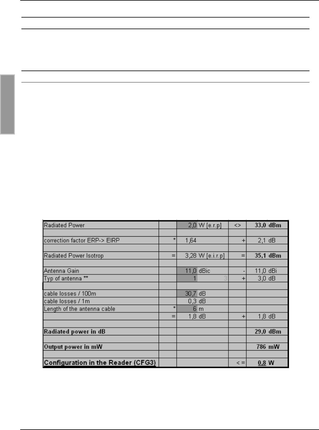
POut = Perp - Antenna Gain + Cable loss + 2,1dB**
** Correction Factor to convert the radiated power from e.r.p to e.i.r.p.
For the calculation of the reader output power POut an Excel file „Calc-RF-Power.xls“ can be used.
Available from Feig Electronic GmbH.
Example:
Table 13: Calculation of the output power
** linear antenna = „0“, circular antenna = „1“
In Table 13: Calculation of the output power the allowed antenna power is shown for the use of the
FEIG standard antenna ANT.U600/270 –EU and a 6m long Belden H155 coaxial cable.

OBID i-scan®Installation ID ISC.LRU3000
FEIG ELECTRONIC GmbH Page 47 of 52 LRU3000 - Manual.doc
E N G L I S H
10.3.2 FCC-Reader
According to the FCC approval, Title 47, Part15 the maximum output power of the reader is limited
to 1 W (30dBm). The maximum radiated power of the antenna should not increase more then 4 W
e.i.r.p.
Due to these facts two different cases have to be considered:
If a linear polarized antenna is used which gain is less then 6 dBi (factor 4), or if a circular polarized
antenna is used which gain is less then 9dBic the reader can always be configured to an output
power of 1W.
Antenna Gain < 6dBi →Pout = 1 W
This would be the case if the FEIG standard antennas ANT.U170/170 -FCC (4dBic) or
ANT.U270/270 -FCC (8,7dBic) are used.
If an antenna is used which gain is more then 6dBi (9dBic) it is necessary to consider the antenna
gain and the attenuation of the antenna cable to calculate the right output power. If a circular po-
larized antenna is used the antenna gain [G]=dBic can be reduced by 3dB. This is the case if the
FEIG standard antenna ANT.U600/270 -FCC is used. In this configuration the maximum output
power of the reader can be calculated in the following way.
POut = 36 dBm (4 W e.i.r.p) – Antenna Gain (in dBi) + Cable Loss (in dB)
POut = 36 dBm (4 W e.i.r.p) – Antenna Gain (in dBic) – 3 dB + Cable Loss (in dB)
The antenna gain of the circular polarized standard antenna ANT.U600/270 is 10,5 dBic. This
could be compared with a gain of 7,5 dBi of a linear polarized antenna (10,5 dBic – 3 dB).
Example :
Antenna ANT.U600/270 and 2 m Belden H155 Coaxial Cable:
Pout= 36 dBm – 10,5 dBic + 3 dB + 0,6 dB
Pout= 36 dBm – 7,5 dBi + 0,6 dB
Pout= 29,1 dBm
Reader Configuration = 0,8 Watt

OBID i-scan®Installation ID ISC.LRU3000
FEIG ELECTRONIC GmbH Page 48 of 52 LRU3000 - Manual.doc
E N G L I S H
Example 2:
Antenna ANT.U600/270 and 6m Belden H155 Coaxial Cable:
Pout= 36 dBm – 10,5 dBic + 3 dB + 1,8 dB
Pout= 36 dBm – 7,5 dBi + 1,8 dB
Pout= 30,3 dBm
Reader Configuration = 1,0 Watt
According to Example 2 it will only be necessary to adapt the output power of the reader when the
antenna ANT.U600/270 is used if the length of the antenna cable is less then 6m.

OBID i-scan®Installation ID ISC.LRU3000
FEIG ELECTRONIC GmbH Page 49 of 52 LRU3000 - Manual.doc
E N G L I S H
11 Radio Approvals
11.1.1 Europe (CE)
When properly used this radio equipment conforms to the essential requirements of Article 3 and
the other relevant provisions of the R&TTE Directive 1999/5/EC of March 99.
Equipment Classification according to ETSI EN 301 489: Class 2

OBID i-scan®Installation ID ISC.LRU3000
FEIG ELECTRONIC GmbH Page 50 of 52 LRU3000 - Manual.doc
E N G L I S H
11.2 USA (FCC)
FCC ID: PJMLRU3000
This device complies with Part 15 of the FCC Rules. Operation is subject to the following
two conditions:
(1) this device may not cause harmful interference, and
(2) this device must accept any interference received, including interference that may
cause undesired operation.
NOTICE:
Changes or modifications made to this equipment not expressly approved by
FEIG ELECTRONIC GmbH may void the FCC authorization to operate this equipment.
NOTE: This equipment has been tested and found to comply with the limits for a Class B digital
device, pursuant to Part 15 of the FCC Rules. These limits are designed to provide reasonable
protection against harmful interference in a residential installation. This equipment generates, uses
and can radiate radio frequency energy and, if not installed and used in accordance with the
instructions, may cause harmful interference to radio communications. However, there is no
guarantee that interference will not occur in a particular installation. If this equipment does cause
harmful interference to radio or television reception, which can be determined by turning the
equipment off and on, the user is encouraged to try to correct the interference by one or more of
the following measures:
- Reorient or relocate the receiving antenna.
- Increase the separation between the equipment and receiver.
- Connect the equipment into an outlet on a circuit different from that to which the receiver is
connected
- Consult the dealer or an experienced radio/TV technician for help.
To reduce potential radio interference to other users, the antenna type and its gain should be so
chosen that the equivalent isotropically radiated power (EIRP) is not more than that permitted for
successful communication.
This device has been designed to operate with the antennas listed below, and having a maximum
gain of 10.5 dBic. Antennas not included in this list or having a gain greater than 10.5 dBic are
strictly prohibited for use with this device. The required antenna impedance is 50 ohms. Lists of
Antennas:
ID.ISC.ANT.U250/250-FCC, ID.ISC.ANT.U170/170-FCC, ID ISC.ANT.U270/270-FCC,
ID ISC.ANT.U600/270-FCC
11.3 Canada compliance statement (IC: 6633A-LRU3000)
Operation is subject to the following two conditions:
(3) this device may not cause interference, and
(4) this device must accept any interference, including interference that may cause undesired op-
eration of the device.
Usually this is followed by the following RSS caution:
Any changes or modifications not expressly approved by the party responsible for compliance
could void the user's authority to operate this equipment.

OBID i-scan®Installation ID ISC.LRU3000
FEIG ELECTRONIC GmbH Page 51 of 52 LRU3000 - Manual.doc
E N G L I S H
12 Technical Data
Mechanical Data
• Housing Plastic enclosure with cooling fin
• Dimensions ( W x H x D ) 261,3 x 157,3 x 68 mm³
10.29 inch x 6.19 inch x 2.68 inch
• Weight 2.0 kg (4.4 lb)
• Enclosure rating IP 53 (with protection cap IP64)
• Color RAL 9003
Electrical Data
Supply voltage
optional:
24 V DC ± 5 % (Noise Ripple : max. 150 mV)
PoE (Power over Ethernet) (min. 42,5 V DC)
(up to 1Watt reader output power)
• Power consumption max. 35 VA
• Operating Frequency
EU Reader
FCC Reader
865,7 – 867,5MHz (4 Channel Plan))
902-928MHz (FCC CFR 47 Part 15.247)
• Transmitting power 300 mW – 4 W (configurable)
(maximum 1W by PoE)
• RF-Diagnostic RF-Channel control, antenna SWR control, internal
overheating control
• Antenna connections
- 4 x multiplexing 4 x SMA socket (50Ω)
• Outputs:
- 2 optocoupler
- 3 relay ( 1 x normal open)
24 V DC / 30 mA (galvanically isolated)
24 V DC / 1 A (switching current), (2 A constant load)
• Inputs
- 5 optocoupler max. 5-10 V DC / 20 mA
• Interfaces - RS232
- RS485
- USB (full speed)
- Ethernet (TCP/IP)

OBID i-scan®Installation ID ISC.LRU3000
FEIG ELECTRONIC GmbH Page 52 of 52 LRU3000 - Manual.doc
E N G L I S H
Functional Feature
• Protocol modes - FEIG ISO Host Mode
- Buffer Reader Mode (Data Filtering and
- Notification Mode buffering)
- Scan Mode
• Supported transponders - EPC class 1 Gen 2
- EM4222 / 4444 (optional)
- 18000-6-B/-C (optional)
• Optical indicators 8 LEDs for operating status and diagnostics
Ambient
• Temperature range
- Operating
- Storage
-25°C to +50°C (-13°F to +122°F)
-25°C to +85°C (-13°F to +185°F)
• Rel. Humidity 5% -95% (not condensing)
• Vibration EN60068-2-6
10 Hz to 150 Hz :0.075 mm / 1 g
• Shock EN60068-2-27
Acceleration : 30 g
Applicable standards
• RF approval
- Europe
- USA
EN 302 208
FCC 47 CFR Part 15
• EMC EN 301 489
• Safety
- Low-Voltage
- Human Exposure
EN 60950
EN 50364