Feig Electronic LRU3000 RFID Reader User Manual Annex No
Feig Electronic GmbH RFID Reader Annex No
Contents
UM

Date: 2012-06-11
Vers. no. 1.12
m. dudde hochfrequenz-technik
Rottland 5a
D-51429 Bergisch Gladbach/ Germany
Tel: +49 2207-96890
Fax +49 2207-968920
Annex no. 5
Functional Description /
User Manual
INSTALLATION
final – public (B)
2013-10-28 – M21016-3e-ID-B
ID ISC.LRU3000 / ID ISC.LRU3500
UHF Long Range Reader

OBID
i-scan
®
UHF
Installation
ID ISC.LRU3000/3500
FEIG ELECTRONIC GmbH Page 2 of 32 M21016-3e-ID-B
Note
Copyright 2013 by
FEIG ELECTRONIC GmbH
Lange Strasse 4
D-35781 Weilburg
Tel.: +49 6471 3109-0
http://www.feig.de
With the edition of this document, all previous editions become void. Indications made in this manual may be
changed without previous notice.
Copying of this document, and giving it to others and the use or communication of the contents thereof are
forbidden without express authority. Offenders are liable to the payment of damages. All rights are reserved
in the event of the grant of a patent or the registration of a utility model or design.
Composition of the information in this document has been done to the best of our knowledge. FEIG
ELECTRONIC GmbH does not guarantee the correctness and completeness of the details given in this
manual and may not be held liable for damages ensuing from incorrect or incomplete information. Since,
despite all our efforts, errors may not be completely avoided, we are always grateful for your useful tips.
The instructions given in this manual are based on advantageous boundary conditions. FEIG ELECTRONIC
GmbH does not give any guarantee promise for perfect function in cross environments and does not give
any guaranty for the functionality of the complete system which incorporates the subject of this document.
FEIG ELECTRONIC call explicit attention that devices which are subject of this document are not designed
with components and testing methods for a level of reliability suitable for use in or in connection with surgical
implants or as critical components in any life support systems whose failure to perform can reasonably be
expected to cause significant injury to a human. To avoid damage, injury, or death, the user or application
designer must take reasonably prudent steps to protect against system failures.
Use Exclusion in Transportation Market: Devices which are subject of this document may NOT be sold,
used, leased, offer for sale, or otherwise transferred, exported, and imported by anyone in the Transportation
Market. “Transportation Market” means (i) Electronic Toll and Traffic Management (ETTM), (ii) Public Sector
Vehicle Registration, Inspection and Licensing Programs, (iii) Railroad Locomotive and Wagon tracking, (iv)
airport based ground transportation management systems (GTMS) and taxi dispatch, (v) revenue based
parking, and (vi) vehicle initiated mobile payment applications, where the RFID sticker/tag is initially attached
to the vehicle but not incorporated at the point of vehicle manufacture.
FEIG ELECTRONIC GmbH assumes no responsibility for the use of any information contained in this docu-
ment and makes no representation that they free of patent infringement. FEIG ELECTRONIC GmbH does
not convey any license under its patent rights nor the rights of others.
OBID® and OBID i-scan® are registered trademarks of FEIG ELECTRONIC GmbH.

OBID
i-scan
®
UHF
Installation
ID ISC.LRU3000/3500
FEIG ELECTRONIC GmbH Page 3 of 32 M21016-3e-ID-B
General information's regarding this document
• The sign "" indicates extensions or changes of this manual compared with the former issue.
• If bits within one byte are filled with "-", these bit spaces are reserved for future extensions or
for internal testing- and manufacturing-functions. These bit spaces must not be changed, as this
may cause faulty operation of the reader.
• The following figure formats are used:
0...9: for decimal figures
0x00...0xFF: for hexadecimal figures,
b0...1 for binary figures.
• The hexadecimal value in brackets "[ ]" marks a control byte (command).

OBID
i-scan
®
UHF
Installation
ID ISC.LRU3000/3500
FEIG ELECTRONIC GmbH Page 4 of 32 M21016-3e-ID-B
Contents
1. Safety Instructions / Warning - Read before start-up ! 6
2. Performance Features of Reader Family ID ISC.LRU3000 7
2.1. Performance features ........................................................................................................ 7
2.2. Available Reader types ..................................................................................................... 7
2.3. Available Accessories ....................................................................................................... 7
3. Installation 8
4. Terminals 9
4.1. Antenna Connection ....................................................................................................... 10
4.2. Power Supply ................................................................................................................... 11
4.2.1. Power Supply via connection X1 ................................................................................ 11
4.2.2. Power Supply via Power over Ethernet (PoE) ............................................................ 12
4.3. Interfaces ......................................................................................................................... 13
4.3.1. Ethernet Interface on connector X2 ............................................................................ 13
4.3.2. USB Interface on connector X3 .................................................................................. 13
4.3.3. USB Interface on connector X4 (WLAN) .................................................................... 13
4.3.4. RS232 Interface on connector X6 .............................................................................. 14
4.3.5. RS485 Interface on connector X6 .............................................................................. 15
4.3.5.1. Address assignment of RS485 for bus operation ........................................... 16
4.3.6. Data-Clock Interface on connector X5 ........................................................................ 16
4.4. Digital Inputs on connector X5 ....................................................................................... 18
4.5. Outputs on connector X5 ................................................................................................ 19
4.5.1. Digital outputs on connector X5 ................................................................................. 19
4.5.2. Relay outputs on connector X5 .................................................................................. 20
5. Operating and Display Elements 22
5.1. Status LEDs ..................................................................................................................... 22

OBID
i-scan
®
UHF
Installation
ID ISC.LRU3000/3500
FEIG ELECTRONIC GmbH Page 5 of 32 M21016-3e-ID-B
5.2. Reset Push Buttons ........................................................................................................ 23
5.3. Reader Power adjustment ............................................................................................... 24
5.3.1. EU-Reader according to EN302 208 .......................................................................... 24
5.3.2. FCC-Reader according to FCC 47 Part 15 ................................................................. 25
6. Technical Data 26
7. Radio Approvals 29
7.1. Europe (CE) ...................................................................................................................... 29
7.2. Declaration of Conformity (Directive 1999/5/EC - R&TTE) ............................................ 30
7.3. USA (FCC) and Canada (IC) ............................................................................................ 31
7.3.1. USA (FCC) and Canada (IC) warning notices ............................................................ 31
7.3.2. Label Information ....................................................................................................... 32
7.3.3. Installation with FCC / IC Approval ............................................................................. 32
7.3.4. USA (FCC) and Canada (IC) approved antennas ...................................................... 32

OBID
i-scan
®
UHF
Installation
ID ISC.LRU3000/3500
FEIG ELECTRONIC GmbH Page 6 of 32 M21016-3e-ID-B
1. Safety Instructions / Warning - Read before start-up !
• The device may only be used for the intended purpose designed by for the manufacturer.
• The operation manual should be conveniently kept available at all times for each user.
• Unauthorized changes and the use of spare parts and additional devices which have not been
sold or recommended by the manufacturer may cause fire, electric shocks or injuries. Such
unauthorized measures shall exclude any liability by the manufacturer.
• The liability-prescriptions of the manufacturer in the issue valid at the time of purchase are valid
for the device. The manufacturer shall not be held legally responsible for inaccuracies, errors,
or omissions in the manual or automatically set parameters for a device or for an incorrect
application of a device.
• Repairs may only be executed by the manufacturer.
• Installation, operation, and maintenance procedures should only be carried out by qualified
personnel.
• Use of the device and its installation must be in accordance with national legal requirements
and local electrical codes .
• When working on devices the valid safety regulations must be observed.
• When installing the device in areas covered under FCC 47 CFR Part 15 a minimum separation
of 23 cm (9 inch) between antenna and the human body must be maintained.
• Special advice for carriers of cardiac pacemakers:
Although this device doesn't exceed the valid limits for electromagnetic fields you should keep
a minimum distance of 25 cm between the device and your cardiac pacemaker and not stay in
an immediate proximity of the device respective the antenna for some time.
OBID
i-scan
®
UHF
Installation
ID ISC.LRU3000/3500
FEIG ELECTRONIC GmbH Page 7 of 32 M21016-3e-ID-B
2. Performance Features of Reader Family ID ISC.LRU3000
2.1. Performance features
The Reader has been developed for reading passive data carriers, so-called „Smart Labels“, using
an operating frequency in the UHF range.
2.2. Available Reader types
The following Readers are available:
Table 1: Available Reader Types
Reader type Description
ID ISC.LRU3500-EU Device version for Europe with PoE (max. 4Watt)
ID ISC.LRU3000-EU Device version for Europe without PoE (max. 2Watt)
ID ISC.LRU3500-FCC Device version for USA with PoE (max. 4Watt)
ID ISC.LRU3000-FCC Device version for USA without PoE (max. 2Watt)
2.3. Available Accessories
The following optional accessories are currently available:
Table 2: Optional Reader Accessories
Reader type
Description
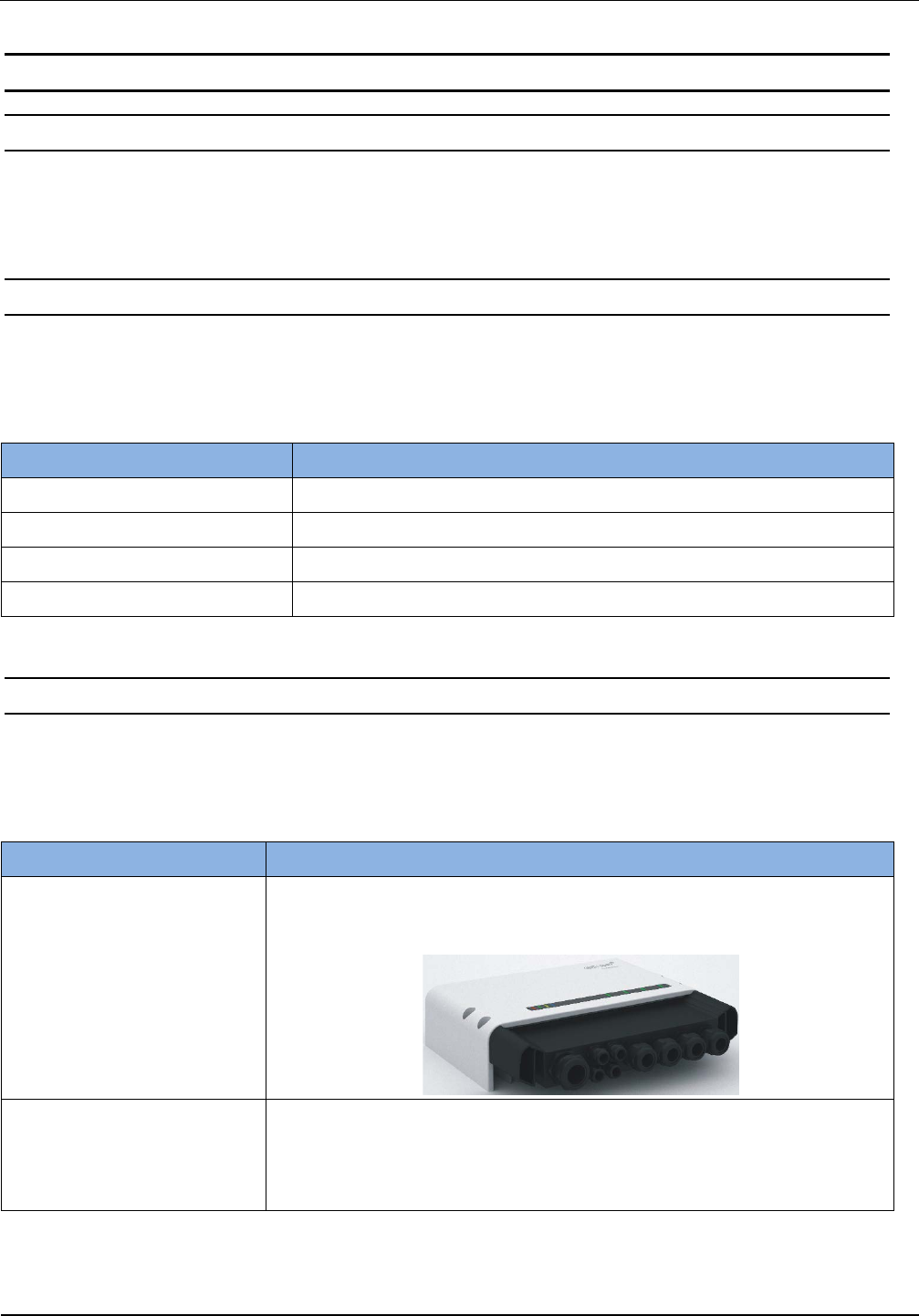
ID ISC.LR.CSC-IP64 Connector
Sealing Cap
Protection cap for IP 64
Art.No.: 3558.000.00
ID ISC.LRU3x00-MS Mounting
Rail Set
Rail Mounting Set for ID ISC.LRU3000/3500
Art.No.: 3831.000.00
OBID
i-scan
®
UHF
Installation
ID ISC.LRU3000/3500
FEIG ELECTRONIC GmbH Page 8 of 32 M21016-3e-ID-B
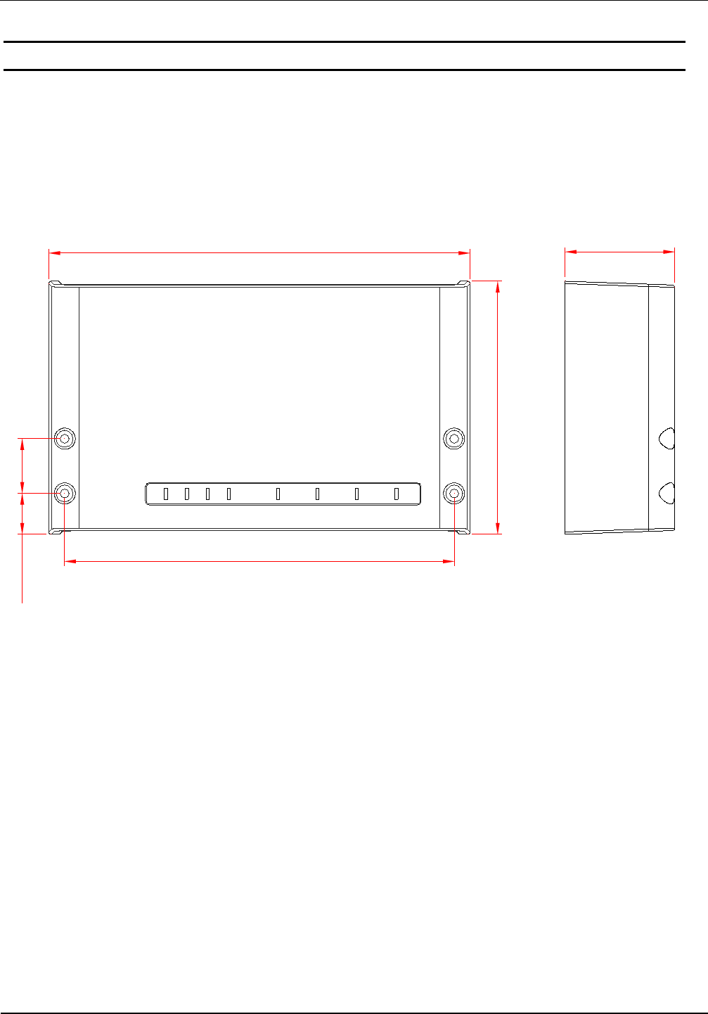
3. Installation
The Reader is designed for wall-mount, including outdoors. Holes for mounting on a wall are
provided in the housing.
It is not necessary to open the reader housing mounting.
261,3 (10.29)
157,3 (6.19)
241,7 (9.52)
34 (1.34)25,5 (1.00)
68 (2.68)
Figure 1: Installation Drawing
OBID
i-scan
®
UHF
Installation
ID ISC.LRU3000/3500
FEIG ELECTRONIC GmbH Page 9 of 32 M21016-3e-ID-B
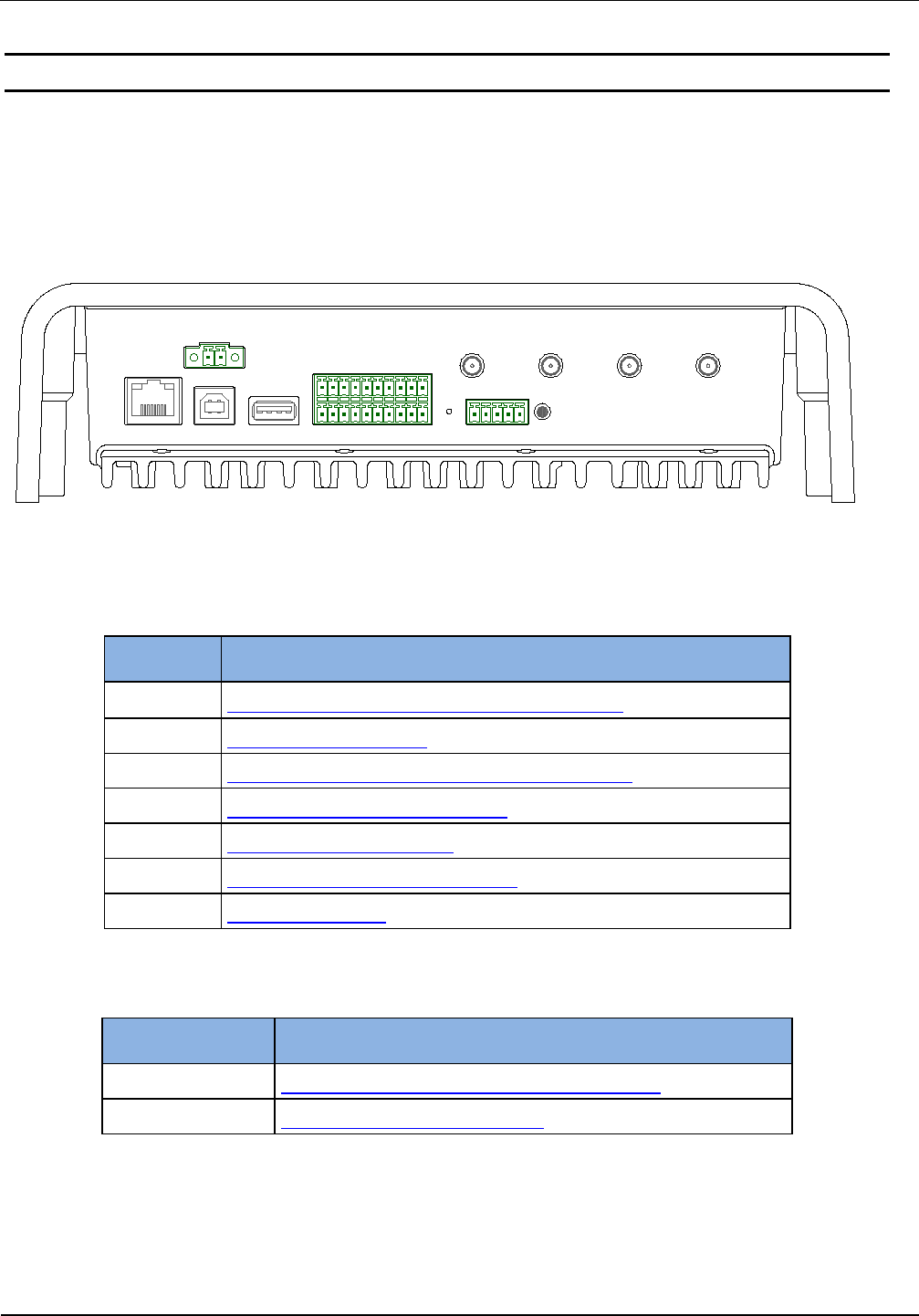
4. Terminals
On the lower side of the reader housing the different cable connectors are positioned. Figure 2:
Connection Overview shows the arrangement of the connectors and Table 3: Connection terminals
shows which connection for the different cables are used for. Table 4: Push button function shows
the available push buttons.
X2 X3 X4
X5
X6
T1 T2
X1 ANT1 ANT2 ANT3 ANT4
Figure 2: Connection Overview
Table 3: Connection terminals
Connector Description
ANT 1-4 Connection of the external antennas (Impedance 50Ω)
X1 Power supply 24VDC +-5%
X2 10/100Tbase network connection with RJ-45 (with PoE)
X3 USB interface for host communication
X4 USB interface for WLAN-Sticks
X5 Digital input and output and relay output
X6 RS232 / 485 interface
Table 4: Push button function
Push button Description
T1 Internal push button for complete configuration reset
T2 External push button for CPU-Reset
OBID
i-scan
®
UHF
Installation
ID ISC.LRU3000/3500
FEIG ELECTRONIC GmbH Page 10 of 32 M21016-3e-ID-B
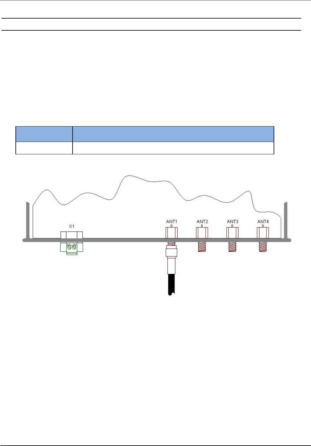
4.1. Antenna Connection
The external SMA antenna connectors are positioned on the lower side of the reader.
The maximum tightening torque for the SMA sockets is 0.45 Nm (4.0 lbf in).
CAUTION:
Exceeding the tightening torque will destroy the plug.
Table 5: External antenna connection
Terminal Description
ANT 1 - 4 Connection for external antennas (input impedance 50Ω)
Figure 3: External antenna connection ANT1-4 and X1 for the power supply
CAUTION:
A direct connection of an antenna to an antenna output with activated DC Voltage (24 VDC,
500 mA) may damage the antenna.
OBID
i-scan
®
UHF
Installation
ID ISC.LRU3000/3500
FEIG ELECTRONIC GmbH Page 11 of 32 M21016-3e-ID-B
4.2. Power Supply
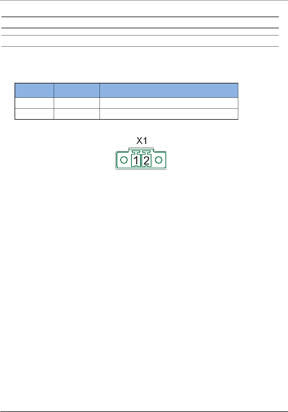
4.2.1. Power Supply via connection X1
The supply voltage of 24 V DC has to be connected to Terminal X1.
Table 6: Pin assignment for power supply
Terminal Abbreviation Description
X1 / Pin 1 VDC Vcc – supply voltage 24VDC +-5%
X1 / Pin 2 GND Ground – supply voltage
Figure 4: Connection for the power supply
CAUTION:
The reader has to be supplied by a limited power supply (e.g. NEC Class 2/LPS power sup-
ply) according IEC EN 60950-1 chapter 2.5, only.
Reversing the polarity of the supply voltage may destroy the device.
Each reader has to be supplied by a separate external power supply.
An operation of an ID ISC.LRU3500 via an external power supply and Power over Ethernet
(PoE) at the same time is not recommended and can cause interferences during operation.
OBID
i-scan
®
UHF
Installation
ID ISC.LRU3000/3500
FEIG ELECTRONIC GmbH Page 12 of 32 M21016-3e-ID-B
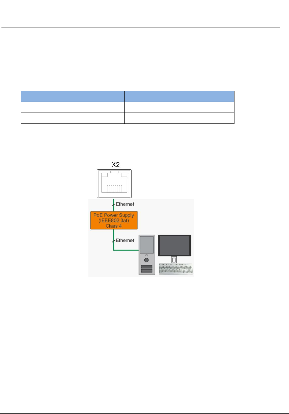
4.2.2. Power Supply via Power over Ethernet (PoE)
Optional the reader (only LRU3500) can be powered via the LAN connector on X2 with the use of a
PoE „Power over Ethernet“ power supply according to IEEE802.3at*, Class4 (30/25,5Watt). The
DC supply can be achieved via the free pin’s 4,5 and 7,8 (Midspan-Power). Also a “Phantom Pow-
ering” (Inline-Power) via the signal pin’s 1,2,3,and 6 is possible. Depending on the cable cross-
section the following cable distances can be used.
Table 7: Maximum cable length if PoE is used
cable cross-section (CAT5...7)
Maximum cable length for PoE
0,4mm ≈ 30m
0,6mm ≈ 70m
* For detailed technical information regarding the 802.3at standard, please refer to the most
recent edition of the corresponding IEEE specification.
Figure 5: LAN and PoE connection
CAUTION:
Take care if PoE is used the maximum reader output power of the reader must be limited to
1Watt.
It must be ensured that the reader is supplied with 42,5 V DC (48 V DC – cable losses) at
least.
This functionality is only available with the reader models ID ISC.LRU3500-EU and ID
ISC.LRU3500-FCC.
An operation of an ID ISC.LRU3500 via an external power supply and Power over Ethernet
(PoE) at the same time is not recommended and can cause interferences during operation.
If Power over Ethernet is used WLAN is not available.
OBID
i-scan
®
UHF
Installation
ID ISC.LRU3000/3500
FEIG ELECTRONIC GmbH Page 13 of 32 M21016-3e-ID-B
4.3. Interfaces
4.3.1. Ethernet Interface on connector X2
The Reader has an integrated 10 / 100 base-T network port for an RJ-45. Connection is made on
X2 and has an automatic “Crossover Detection” according to the 100BASE-T Standard.
With structured cabling CAT 5 cables should be used. This ensures a reliable operation at 10 Mbps
or 100 Mbps.
The prerequisite for using TCP/IP protocol is that each device has a unique address on the net-
work. All Readers have a factory set IP address.
Table 8: Standard factory configuration of the Ethernet connection
Network Address
IP-Adresse 192.168.10.10
Subnet-Mask 255.255.255.0
Port 10001
DHCP OFF
NOTE:
The reader is equipped with a DHCP ready Ethernet Interface.
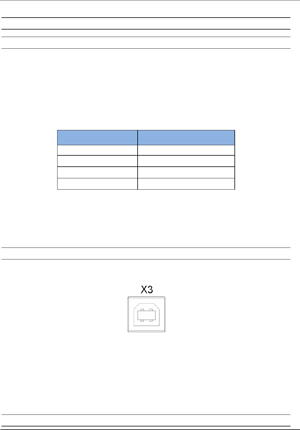
4.3.2. USB Interface on connector X3
The USB socket on the board is terminal X3. The pinout is standardized. The data rate is reduced
to 12 Mbit (USB full speed). A standard USB-cable can be used.
Figure 6: USB-Interface for host communication
NOTE:
The length of the USB-cable can have a max. of 5m (20 inch). It is not allowed to use longer
cables.
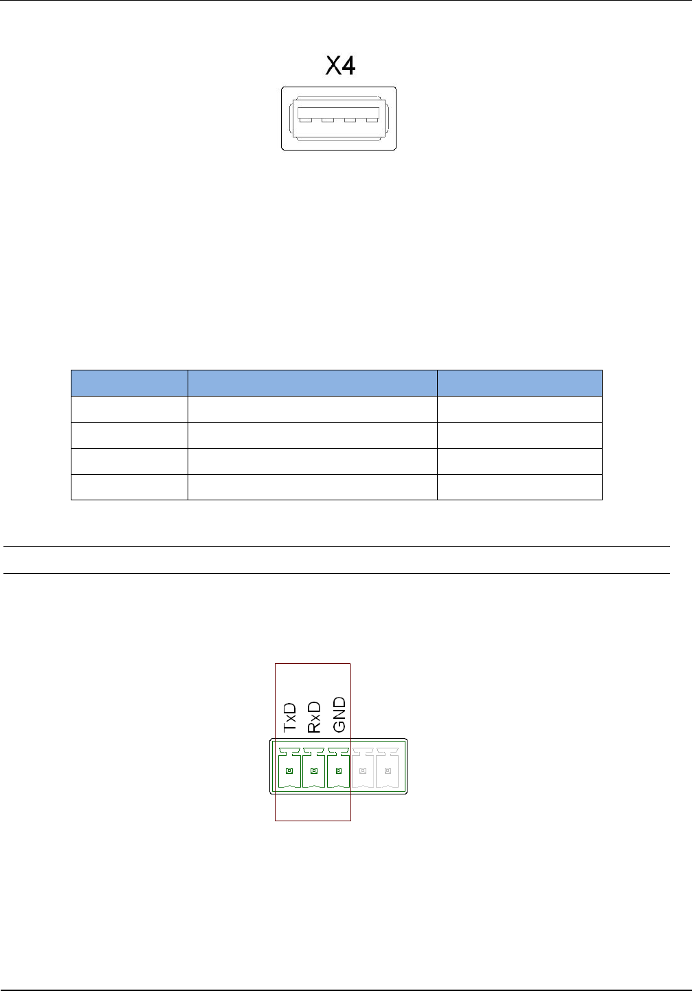
4.3.3. USB Interface on connector X4 (WLAN)
OBID
i-scan
®
UHF
Installation
ID ISC.LRU3000/3500
FEIG ELECTRONIC GmbH Page 14 of 32 M21016-3e-ID-B
The USB-Port X4 can be used for a standard WLAN-USB-Stick
Figure 7: USB-Interface for external WLAN stick
NOTE:
WLAN shall not be used when the reader is powered via Power over Ethernet (PoE)
The following table gives an overview about successfully tested Wireless LAN Sticks
Table 9: Successfully tested WLAN Sticks
Manufacturer
Description
Model
Buffalo Wireless-N NFiniti High Power WLI-UC-G300HP
Buffalo Wireless –N NFiniti WLI-UC-G300N
Cisco / Linksys Wireless Network USB Adapter WUSB100
Netgear Wireless-G 54 USB Adapter WG111 v3
4.3.4. RS232 Interface on connector X6
The RS232 interface is connected on X6. The transmission parameters can be configured by
means of software protocol.
Figure 8: RS232 interface pin-outs on X6
OBID
i-scan
®
UHF
Installation
ID ISC.LRU3000/3500
FEIG ELECTRONIC GmbH Page 15 of 32 M21016-3e-ID-B
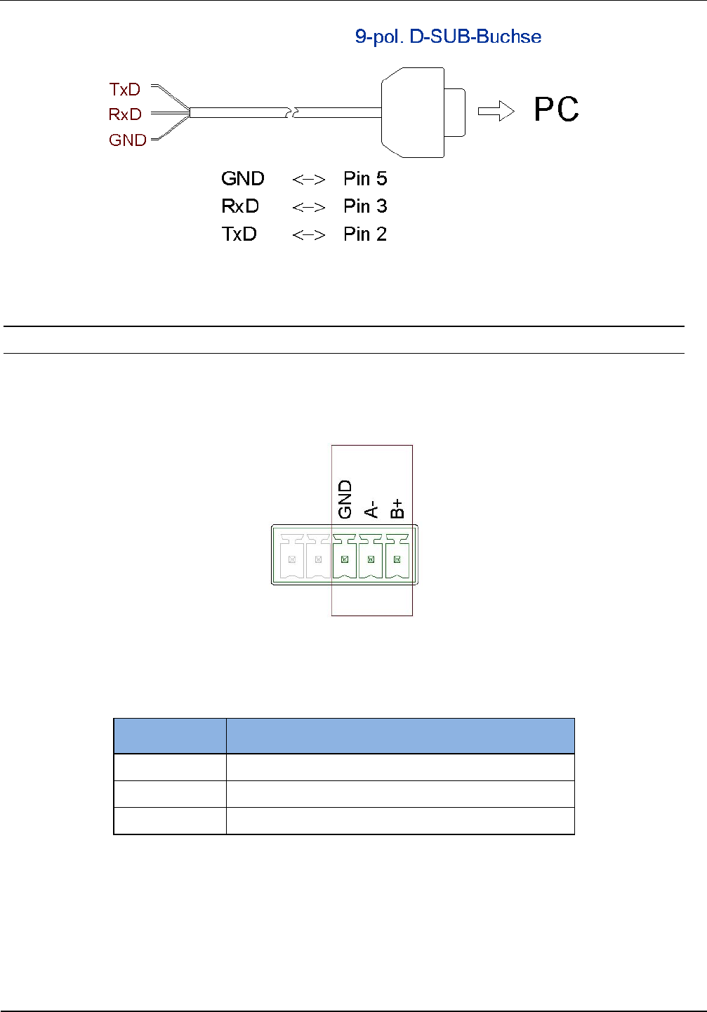
Figure 9: Wiring example for connecting the RS232 interface RS485-Schnittstelle X6
4.3.5. RS485 Interface on connector X6
The connection of the RS485 interface take place via the X6 connector as well. The interface pa-
rameter can be configured via software protocols.
Figure 10: RS485 interface pin-outs on X6 (RS485-Interface):
Table 10: RS485 interface pin-outs
Abbreviation Description
GND RS485 – GND
A- RS485 – (A -)
B+ RS485 – (B +)
OBID
i-scan
®
UHF
Installation
ID ISC.LRU3000/3500
FEIG ELECTRONIC GmbH Page 16 of 32 M21016-3e-ID-B
4.3.5.1. Address assignment of RS485 for bus operation
For bus operation the Reader can be assigned the required bus address via software.
The address is assigned by the host computer. The software is used to assign addresses “0”
through “254” to the Reader.
A potential termination of the interface bus can be configured by the software as well.
NOTE:
Since all Readers are factory set with address „0“, they must be connected and configured
one after the other.
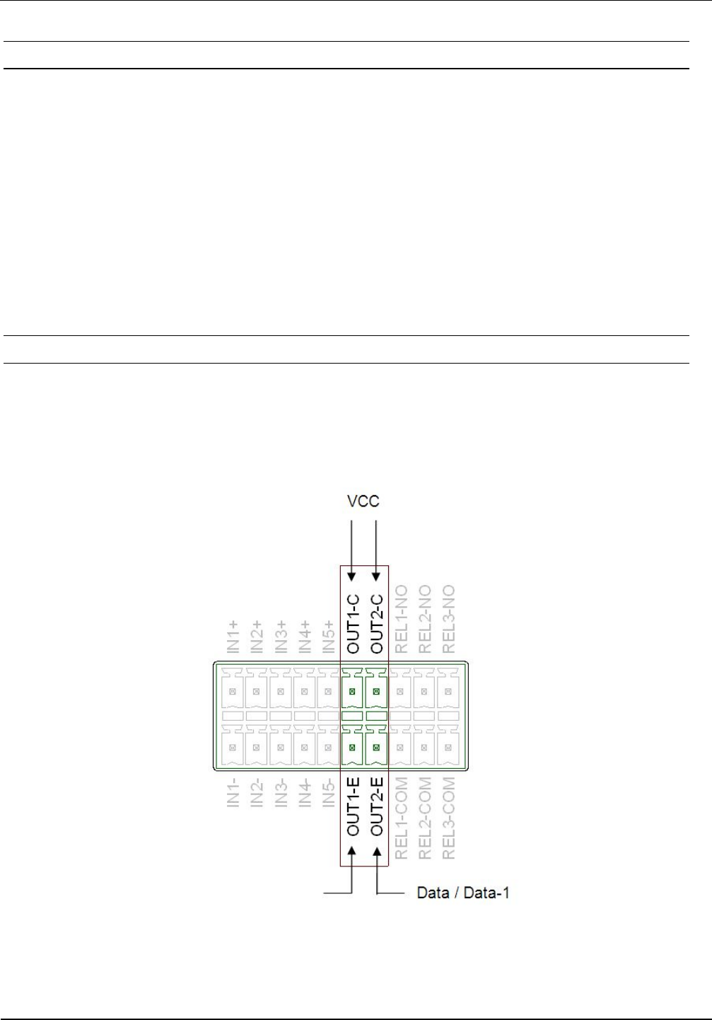
4.3.6. Data-Clock Interface on connector X5
The connection of the data-clock interface take place via the digital Outputs OUT1 and OUT2 at
connector X5. The wire for the clock needs to be connected to connector OUT1-C, the wire for the
data needs to be connected to connector OUT2-C.
Figure 11: Data-Clock Interface on connector X5
NOTE:
Clock / Data-0
OBID
i-scan
®
UHF
Installation
ID ISC.LRU3000/3500
FEIG ELECTRONIC GmbH Page 17 of 32 M21016-3e-ID-B
The data-clock interface is only available in Scan-Mode.
The data-clock interface cannot be used to configure the reader.
The digital outputs OUT1 and OUT2 are not available, if the data-clock interface is activated.
The data as well as the clock need to be supplied with an external voltage. The output is
configured for max. 24 V DC / 30 mA.
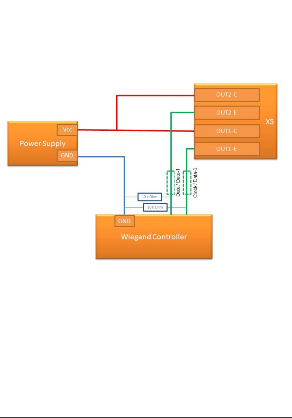
Figure 12: Wiring Example
NOTE:
Please consider possible limitations of the Wiegand Controller regarding the used supply
voltage.
In dependency on the inner circuit of the used Wiegand Controller it is necessary to use
external serial resistors to limit the current on the data and clock wires.
The necessity of the external pull down resistor is depending on the inner circuit of the
used Wiegand Controller
OBID
i-scan
®
UHF
Installation
ID ISC.LRU3000/3500
FEIG ELECTRONIC GmbH Page 18 of 32 M21016-3e-ID-B
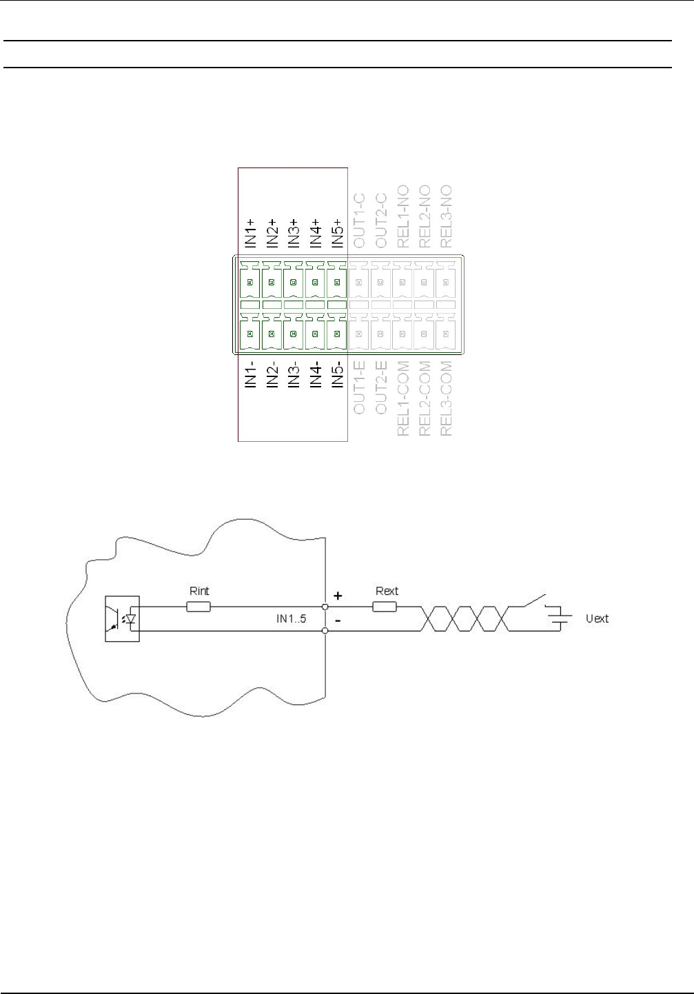
4.4. Digital Inputs on connector X5
The optocouplers on Terminal X5 are galvanically isolated from the Reader electronics and must
therefore be externally supplied.
Figure 13: Optocoupler pin-outs IN1 – IN5
Figure 14: Internal and possible external wiring of the optocoupler inputs
Optocoupler input (X5/1-5):
The input LED associated with the optocoupler is connected internally to a series resistor of 500 Ω.
For supply voltages of greater than 10V the input current must be limited to max. 20 mA by means
of an additional series resistor (see Fehler! Verweisquelle konnte nicht gefunden werden.).
Table 11 shows the necessary external resistors for various external voltages Uext.
OBID
i-scan
®
UHF
Installation
ID ISC.LRU3000/3500
FEIG ELECTRONIC GmbH Page 19 of 32 M21016-3e-ID-B
Table 11: Required external series resistor Rext
External voltage Uext Required external series resistor Rext
5 V ... 10 V ---
11 V ... 15 V 270 Ω
16 V ... 20 V 560 Ω
21 V ... 24 V 820 Ω
NOTE:
The input is configured for a maximum input voltage of 5-10 V DC and an input current of
max. 20 mA.
Polarity reversal or overload on the input will destroy it.
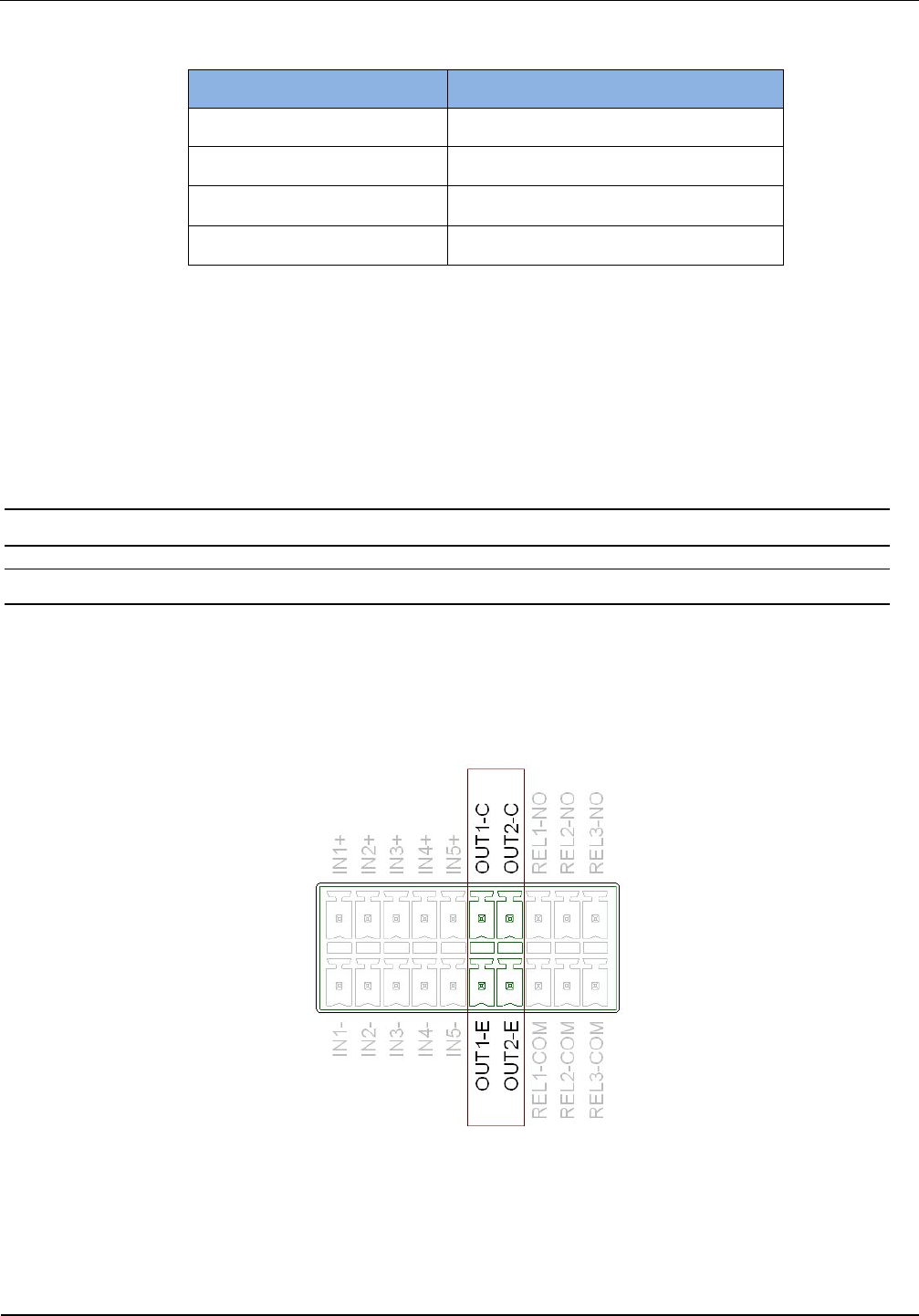
4.5. Outputs on connector X5
4.5.1. Digital outputs on connector X5
Optocoupler output (X5/1-2):
The transistor connections, collector and emitter, of the optocoupler output are galvanically isolated
from the Reader electronics and are carried to the outside without any internal ancillary circuitry on
Terminal X5. The output must therefore be powered by an external power supply.
Figure 15: Optocoupler -Outputs OUT1-2
OBID
i-scan
®
UHF
Installation
ID ISC.LRU3000/3500
FEIG ELECTRONIC GmbH Page 20 of 32 M21016-3e-ID-B
Figure 16: Internal and possible external wiring of the optocoupler-outputs OUT1-2
CAUTION:
The output is configured for max. 24 V DC / 30 mA.
Polarity reversal or overload on the output will destroy it.
The output is intended for switching resistive loads only.
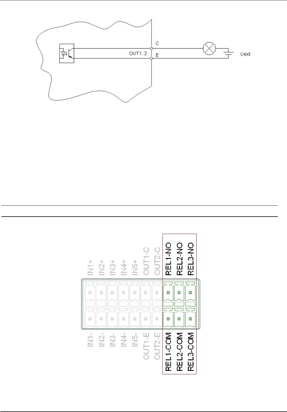
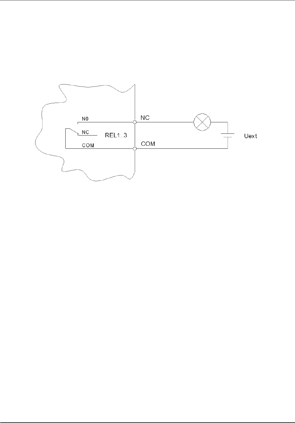
4.5.2. Relay outputs on connector X5
There are 3 relay outputs available on connector X5.
Figure 17: Relay output pin-outs REL1-3
OBID
i-scan
®
UHF
Installation
ID ISC.LRU3000/3500
FEIG ELECTRONIC GmbH Page 21 of 32 M21016-3e-ID-B
CAUTION:
The relay output is configured for max. 24 V DC / 2 A constant load.
The switching current must not exceed 1A.
The relay output is intended for switching resistive loads only. If an inductive load is con-
nected, the relay contacts must be protected by means of an external protection circuit.
Figure 18: Internal and possible external wiring of the relay output
OBID
i-scan
®
UHF
Installation
ID ISC.LRU3000/3500
FEIG ELECTRONIC GmbH Page 22 of 32 M21016-3e-ID-B
5. Operating and Display Elements
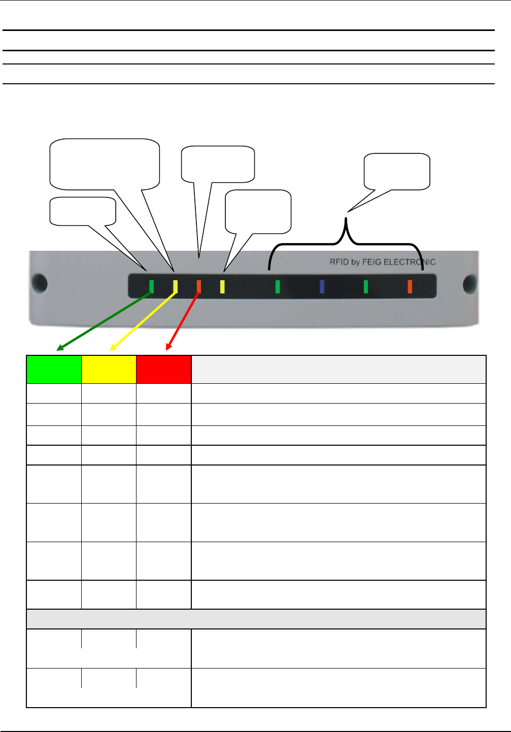
5.1. Status LEDs
Table 12: Configuration of the LEDs
Green Yellow Red Description
ON OFF ON Boot sequence (ca.10s) after power on
FLASH OFF OFF Normal Reader operation (without Host communication)
FLASH BLINKT OFF Reader receives a valid protocol from host
FLASH OFF ON RF Warning [0x84] (without host communication)
FLASH
(alternat-
ing) OFF FLASH
(alternat-
ing)
Firmware Activation necessary [0x17] /
Wrong Firmware [0x18]
FLASH
(synchro-
nous) OFF FLASH
(synchro-
nous) RFC Hardware Error [0xF1]
OFF FLASH
(synchro-
nous)
FLASH
(synchro-
nous)
Hardware Warning
(ACC EEPROM Error / RFC not detected)
FLASH OFF FLASH
(fast) USB Host Error
Firmware Update:
FLASH FLASH FLASH Firmware transfer from host to reader
(Please do not switch off the reader or disconnect the interface cable)
(light in sequence)
FLASH FLASH FLASH Firmware flash into EEPROM.
(Please do not switch off the reader or disconnect the interface cable)
synchronous
ANT 1- 4
RUN
Host
Communication Warning
Input
Output
OBID
i-scan
®
UHF
Installation
ID ISC.LRU3000/3500
FEIG ELECTRONIC GmbH Page 23 of 32 M21016-3e-ID-B
Green Yellow Red Description
Configurations-Reset:
FLASH FLASH FLASH While T1 is pushed and hold for maximal 5s
(light in sequence)
ON ON ON After T1 has been pushed and hold for 5s. Configuration
Reset has been finished.
Input / Output LED (yellow):
Configurable LED. Can display the status of a digital input or output
ANT 1 – 4:
Green HF Power switched on
Blue Tag-Detect
Red Antenna impedance error (> 50Ohm or <50Ohm)
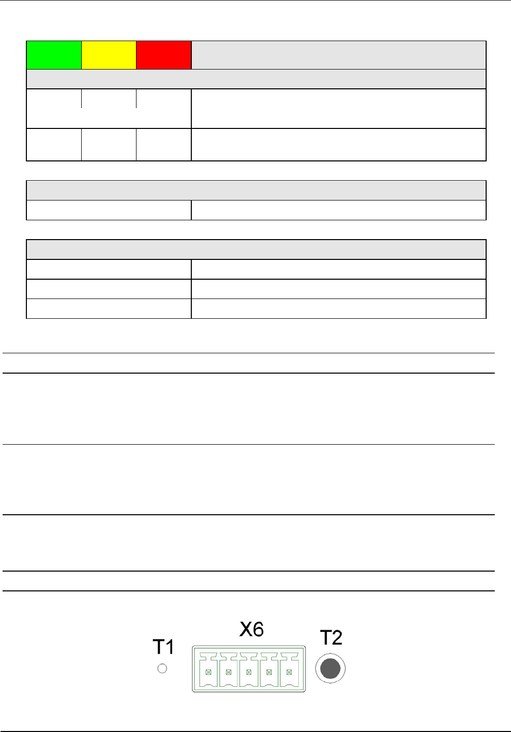
5.2. Reset Push Buttons
Figure 19 shows the position of the reset push button’s T1 and T2.
At the right side of the connector X6 the push button T2 is positioned. With this push button a CPU-
Reset can be performed.
With the push button T1 within the reader housing on left side of X3 a complete con-
figuration reset can be performed. For performing a reset you should use a pa-
per clip and push the button T1 for at least 5 s until the 3 status LED’s (left
side) are switched on continuously, see 5.1. Status LEDs
Table 12: Configuration of the LEDs
.
Table 12: Configuration of the LEDs
Figure 19: Position of the reset-switches T1 and T2
OBID
i-scan
®
UHF
Installation
ID ISC.LRU3000/3500
FEIG ELECTRONIC GmbH Page 24 of 32 M21016-3e-ID-B
5.3. Reader Power adjustment
To achieve the optimum reading performance it is necessary to set the reader output power to the
highest allowed value. This depends on the used reader type (EU / FCC) and the regulation in the
country were the reader is used.
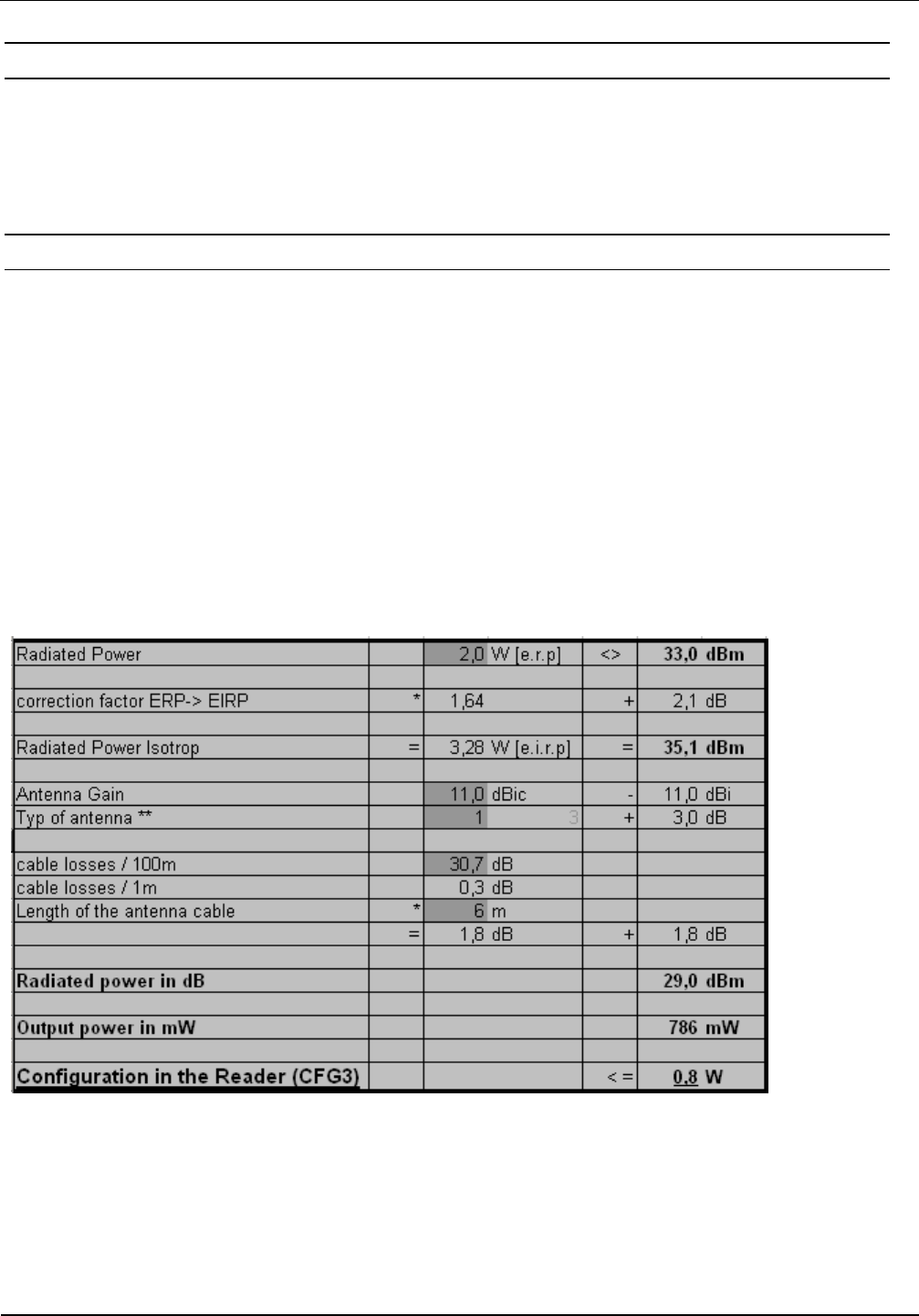
5.3.1. EU-Reader according to EN302 208
According to the standard EN302 208 the maximum radiated power is 2 W e.r.p. (Effective Radiat-
ed Power) in countries of the European Union. The in the reader configured output power Pout de-
pends on the antenna gain in dBi and the attenuation of the antenna cable. If a circular polarized
antenna is used the antenna gain [dBic] can be reduced by 3dB. At a linear polarized antenna the
maximum linear antenna gain [dBi] must be used.
POut = Perp - Antenna Gain + Cable loss + 2,1dB**
** Correction Factor to convert the radiated power from e.r.p to e.i.r.p.
For the calculation of the reader output power POut an Excel file „Calc-RF-Power.xls“ can be used.
Available from Feig Electronic GmbH.
Example:
** linear antenna = „0“, circular antenna = „1“
Figure 20: Calculation of the output power
In Figure 20 the allowed antenna power is shown for the use of the FEIG standard antenna
ANT.U600/270 –EU and a 6m long Belden H155 coaxial cable.

OBID
i-scan
®
UHF
Installation
ID ISC.LRU3000/3500
FEIG ELECTRONIC GmbH Page 25 of 32 M21016-3e-ID-B
5.3.2. FCC-Reader according to FCC 47 Part 15
According to the FCC approval, Title 47, Part15 the maximum output power of the reader is limited
to 1 W (30dBm). The maximum radiated power of the antenna should not increase more then 4 W
e.i.r.p. Due to these facts two different cases have to be considered:
If a linear polarized antenna is used which gain is less then 6 dBi (factor 4), or if a circular polarized
antenna is used which gain is less then 9dBic the reader can always be configured to an output
power of 1W.
Antenna Gain < 6dBi → Pout = 1 W
This would be the case if the FEIG standard antennas ANT.U170/170 -FCC (4dBic) or
ANT.U270/270 -FCC (8,7dBic) are used.
If an antenna is used which gain is more then 6dBi (9dBic) it is necessary to consider the antenna
gain and the attenuation of the antenna cable to calculate the right output power. If a circular polar-
ized antenna is used the antenna gain [G]=dBic can be reduced by 3dB. This is the case if the
FEIG standard antenna ANT.U600/270 -FCC is used. In this configuration the maximum output
power of the reader can be calculated in the following way.
POut = 36 dBm (4 W e.i.r.p) – Antenna Gain (in dBi) + Cable Loss (in dB)
POut = 36 dBm (4 W e.i.r.p) – Antenna Gain (in dBic) – 3 dB + Cable Loss (in dB)
The antenna gain of the circular polarized standard antenna ANT.U600/270 is 10,5 dBic. This
could be compared with a gain of 7,5 dBi of a linear polarized antenna (10,5 dBic – 3 dB).
Example 1:
Antenna ANT.U600/270 and 2 m Belden H155 Coaxial Cable:
Pout= 36 dBm – 10,5 dBic + 3 dB + 0,6 dB
Pout= 36 dBm – 7,5 dBi + 0,6 dB
Pout= 29,1 dBm
Reader Configuration = 0,8 Watt
Example 2:
Antenna ANT.U600/270 and 6m Belden H155 Coaxial Cable:
Pout= 36 dBm – 10,5 dBic + 3 dB + 1,8 dB
Pout= 36 dBm – 7,5 dBi + 1,8 dB
Pout= 30,3 dBm
Reader Configuration = 1,0 Watt
According to Example 2 it will only be necessary to adapt the output power of the reader when the
antenna ANT.U600/270 is used if the length of the antenna cable is less then 6m.

OBID
i-scan
®
UHF
Installation
ID ISC.LRU3000/3500
FEIG ELECTRONIC GmbH Page 26 of 32 M21016-3e-ID-B
6. Technical Data
MECHANICAL DATA
Housing Aluminum powder-coated
Dimension (W x H x D) 261,3 mm x 157,3 mm x 68 mm)
10.29 inch x 6.19 inch x 2.68 inch
Weight 2,0 kg (4.4 lb)
Protection Class IP 53 (with protection cap IP64)
Colour RAL 9003 (Signal White)
ELECTRICAL DATA
Power Supply
• ID ISC.LRU3000
• ID ISC.LRU3500
24 V DC ± 5 % (Noise Ripple: max. 150 mV)
24 V DC ± 5 % (Noise Ripple: max. 150 mV)
or Power over Ethernet (min. 42,5 V DC)
Power Consumption max. 35 W
Operating Frequency
• EU-Reader
• FCC-Reader
865 MHz to 868 MHz (EN 302208)
902 MHz to 928 MHz (FCC47 Part15)
RF-Power
• ID ISC.LRU3000
• ID ISC.LRU3500
300 mW to max. 2 W configurable
300 mW to max. 4 W configurable
max. 1 W if powered via Power over Ethernet
Antenna Connection
• ID ISC.LRU3000
• ID ISC.LRU3500
4 x SMA female (50 Ω), internal Multiplexer
4 x SMA female (50 Ω), internal Multiplexer,
optional a DC voltage of 24 V DC / 500 mA
can be activated at the antenna output
Outputs
• 2 x Optocoupler
• 3 x Relay (1 x normal open)
24 V DC / 30 mA (galvanically isolated)
24 V DC / 1 A (switching current), (2A con-
stant load)

OBID
i-scan
®
UHF
Installation
ID ISC.LRU3000/3500
FEIG ELECTRONIC GmbH Page 27 of 32 M21016-3e-ID-B
Inputs
• 5 x Optocoupler
max. 5-10 V DC / 20 mA
Interfaces
RS232, RS485, USB (full Speed), Ethernet,
USB Host, Data-Clock
FUNCTIONAL PROPERTIES
Protocol Modes FEIG ISO HOST Mode (Advanced Protocol
Frame)
Buffered Read Mode
Scan Mode
Notification Mode
Automatic Data
Buffering and
Filtering
Supported Transponder Types EPC Class 1 Generation 2
ISO 18000-6-C (Upgrade Code required)
further transponder types possible on demand
Optical Indicators 8 LEDs for operating status and diagnostics
Operating System Linux (64 MB RAM, 256 MB Flash)
Further Features Anticollision
RSSI
Real Time Clock
RF-Channel monitoring
Antenna SWR monitoring
Temperature Monitoring*
AMBIENT CONDITIONS
Temperature Range
• Operation
• Storage
-25 °C to +55 °C
-25 °C to +50 °C (only LRU3500 with PoE)
-25 °C to +85 °C
Humidity 5 % to 95 % non-condensing
* Caution: Overheating of the device may result in performance losses. It is recommended to activate the RF of the reader only if there is a transponder in
the detection range of an antenna.

OBID
i-scan
®
UHF
Installation
ID ISC.LRU3000/3500
FEIG ELECTRONIC GmbH Page 28 of 32 M21016-3e-ID-B
Vibration EN 60068-2-6
10 Hz to 150 Hz: 0,075 mm / 1 g
Shock EN 60068-2-27
Acceleration 30 g
APPLICABLE STANDARDS
Radio Regulation
• Europe
• USA
• Canada
EN 302 208
FCC 47 CFR Part 15
IC RSS-Gen, RSS-210
EMC EN 301 489
Safety
• Low Voltage
• Human Exposure
EN 60950
EN 50364

OBID
i-scan
®
UHF
Installation
ID ISC.LRU3000/3500
FEIG ELECTRONIC GmbH Page 29 of 32 M21016-3e-ID-B
7. Radio Approvals
7.1. Europe (CE)
When properly used this radio equipment conforms to the essential requirements of Article 3 and
the other relevant provisions of the R&TTE Directive 1999/5/EC of March 99.
Performance Classification according to ETSI EN 301 489: Class 2
OBID
i-scan
®
UHF
Installation
ID ISC.LRU3000/3500
FEIG ELECTRONIC GmbH Page 30 of 32 M21016-3e-ID-B
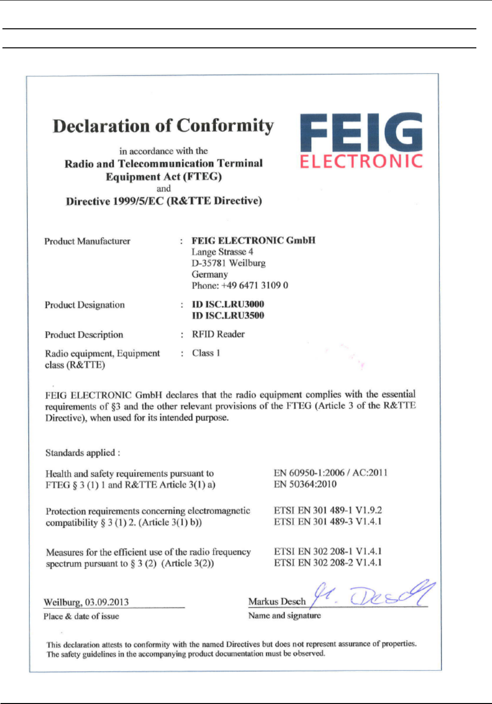
7.2. Declaration of Conformity (Directive 1999/5/EC - R&TTE)
Figure 21: Declaration of Conformity

OBID
i-scan
®
UHF
Installation
ID ISC.LRU3000/3500
FEIG ELECTRONIC GmbH Page 31 of 32 M21016-3e-ID-B
7.3. USA (FCC) and Canada (IC)
7.3.1. USA (FCC) and Canada (IC) warning notices
Product name: ID ISC.LRU3000-FCC
ID ISC.LRU3500-FCC
Reader name:
ID ISC.LRU3000-FCC
ID ISC.LRU3500-FCC
FCC ID:
IC:
PJMLRU3000
6633A-LRU3000
Notice for USA and
Canada
This device complies with Part 15 of the FCC Rules and with
RSS-210 of Industry Canada.
Operation is subject to the following two conditions.
(1) this device may not cause harmful interference, and
(2) this device must accept any interference received,
including interference that may cause undesired operation.
Unauthorized modifications may void the authority granted under
Federal communications Commission Rules permitting the operation
of this device.
This equipment has been tested and found to comply with the l
imits for
a Class A digital device, pursuant to Part 15 of the FCC Rules. These
limits are designed to provide reasonable protection against harmful
interference when the equipment is operated in a commercial
environment. This equipment generates, uses, and can radiate radio
frequency energy and, if not installed and used in accordance with the
instruction manual, may cause harmful interference to radio
communications. Operation of this equipment in a residential area is
likely to cause harmful interference in which case the user will be
required to correct the interference at his own expense.
Le présent appareil est conforme aux CNR d'Industrie Canada appli-
cables aux appareils radio exempts de licence. L'exploitation est auto-
risée aux deux conditions suivantes :
(1) l'appareil ne doit pas produire de brouillage, et
(2) l'utilisateur de l'appareil doit accepter tout brouillage radioélectrique
subi, même si le brouillage est susceptible d'en compromettre le fonc-
tionnement.
Warning: Changes or modification made to this equipment not expressly approved by
FEIG ELECTRONIC GmbH may void the FCC authorization to operate this equipment.

OBID
i-scan
®
UHF
Installation
ID ISC.LRU3000/3500
FEIG ELECTRONIC GmbH Page 32 of 32 M21016-3e-ID-B
7.3.2. Label Information
The following information must be placed at the outer side of the housing in which the reader is
mounted.
Contains FCC ID PJMLRU3000
Contains IC: 6633A-LRU3000
7.3.3. Installation with FCC / IC Approval
FCC-/IC-NOTICE: To comply with FCC Part 15 Rules in the United States / with IC Radio Stand-
ards in Canada, the system must be professionally installed to ensure compliance with the Part 15
certification / IC certification. It is the responsibility of the operator and professional installer to en-
sure that only certified systems are deployed in the United States / Canada.
7.3.4. USA (FCC) and Canada (IC) approved antennas
This radio transmitter (identify the device by certification number, or model number if Category II)
has been approved by Industry Canada to operate with the antenna types listed below with maxi-
mum permission gain and required antenna impedance for each antenna type indicated. Antenna
types, not included in this list, having a gain greater than the maximum gain indicated for that type,
are strictly prohibited for use with this device
Le présent émetteur radio (identifier le dispositif par son numéro de certification ou son numéro de
modèle s’il fait partie du matériel de catégorie I) a été approuvé par Industrie Canada pour fonc-
tionner avec les types d’antenne ’énoncé ci-dessus et ayant un gain admissible maximal et
l’impédance requise pour chaque type d’antenne. Les types d’antenne non inclus dans cette liste,
ou dont le gain est supérieur au gain maximal indiqué, sont strictement interdits pour l’exploitation
de l’émetteur
Following antennas are approved by FCC according FCC Part 15 and IC Canada according
RS210
• ID ISC.ANT.U170/170-FCC (4.0 dBic)
• ID ISC.ANT.U270/270-FCC (9.0 dBic)
• ID ISC.ANT.U600/270-FCC (10,5 dBic)