Feig Electronic LRU3000 RFID Reader User Manual Annex No
Feig Electronic GmbH RFID Reader Annex No
UserManual.wiki
>
Feig Electronic
>
LRU3000 User Manual
>
LRU3000 UM
Contents
1.
User Manual
2.
User Manaul II
3.
UM
UM
Navigation menu
Upload a User Manual
Namespaces
Wiki Guide
HTML
PDF
Info
Views
User Manual
Discussion / Help
Navigation
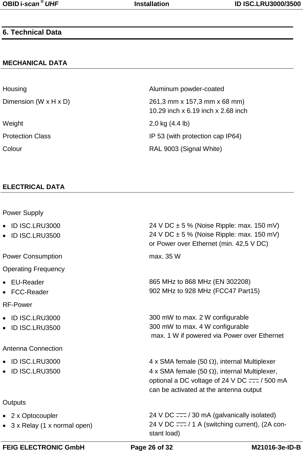
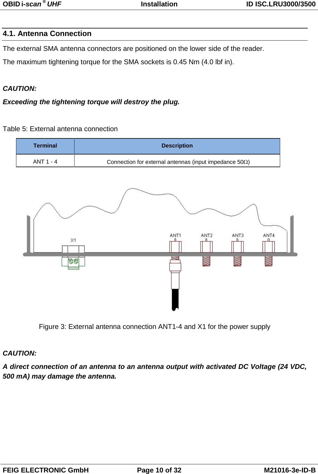
![OBID i-scan ® UHF Installation ID ISC.LRU3000/3500 FEIG ELECTRONIC GmbH Page 3 of 32 M21016-3e-ID-B General information's regarding this document • The sign "" indicates extensions or changes of this manual compared with the former issue. • If bits within one byte are filled with "-", these bit spaces are reserved for future extensions or for internal testing- and manufacturing-functions. These bit spaces must not be changed, as this may cause faulty operation of the reader. • The following figure formats are used: 0...9: for decimal figures 0x00...0xFF: for hexadecimal figures, b0...1 for binary figures. • The hexadecimal value in brackets "[ ]" marks a control byte (command).](https://usermanual.wiki/Feig-Electronic/LRU3000.UM/User-Guide-2177331-Page-4.png)
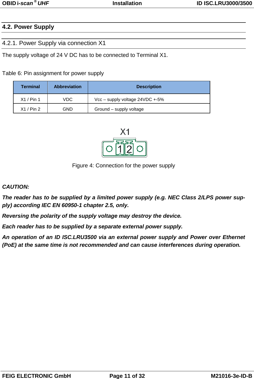
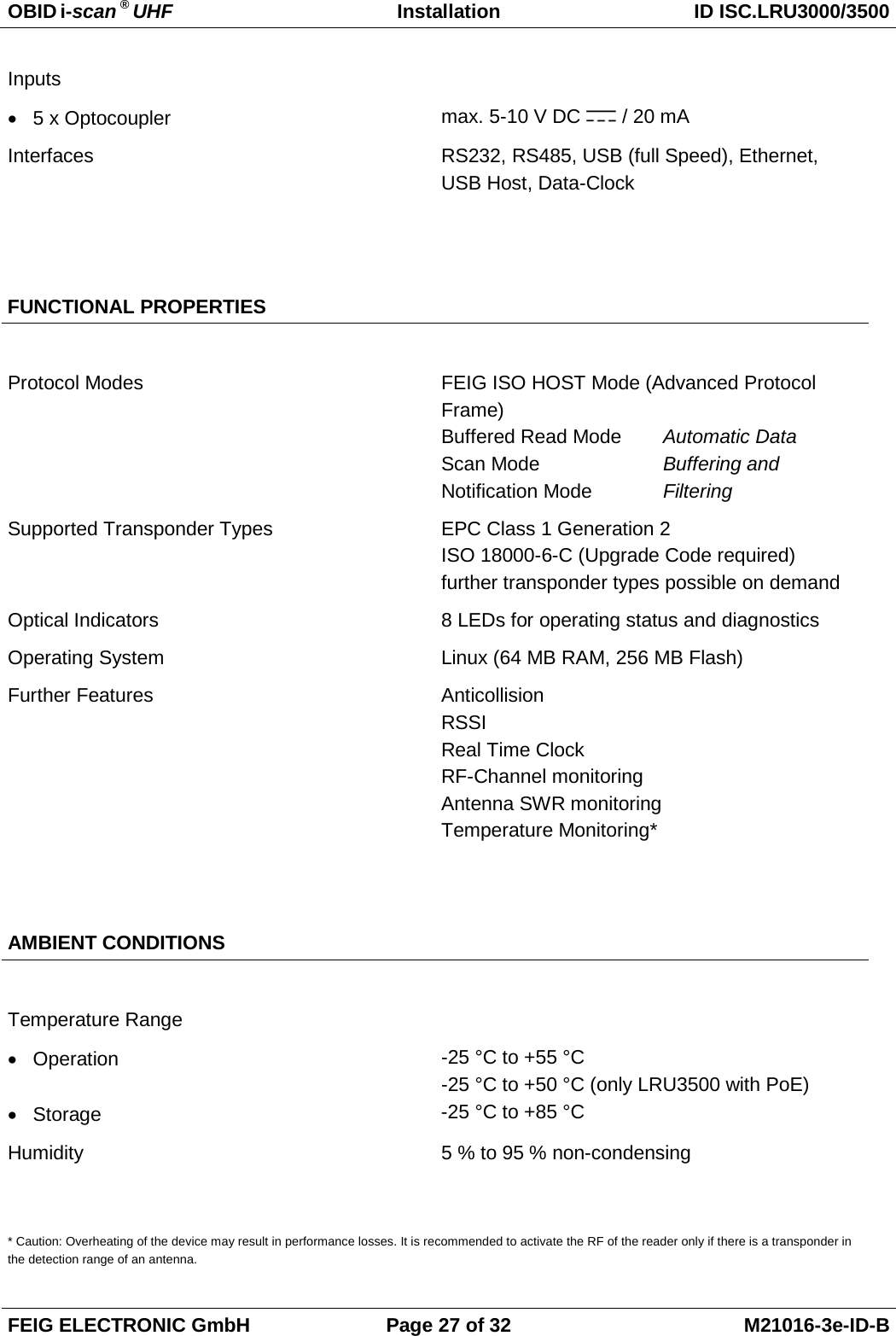
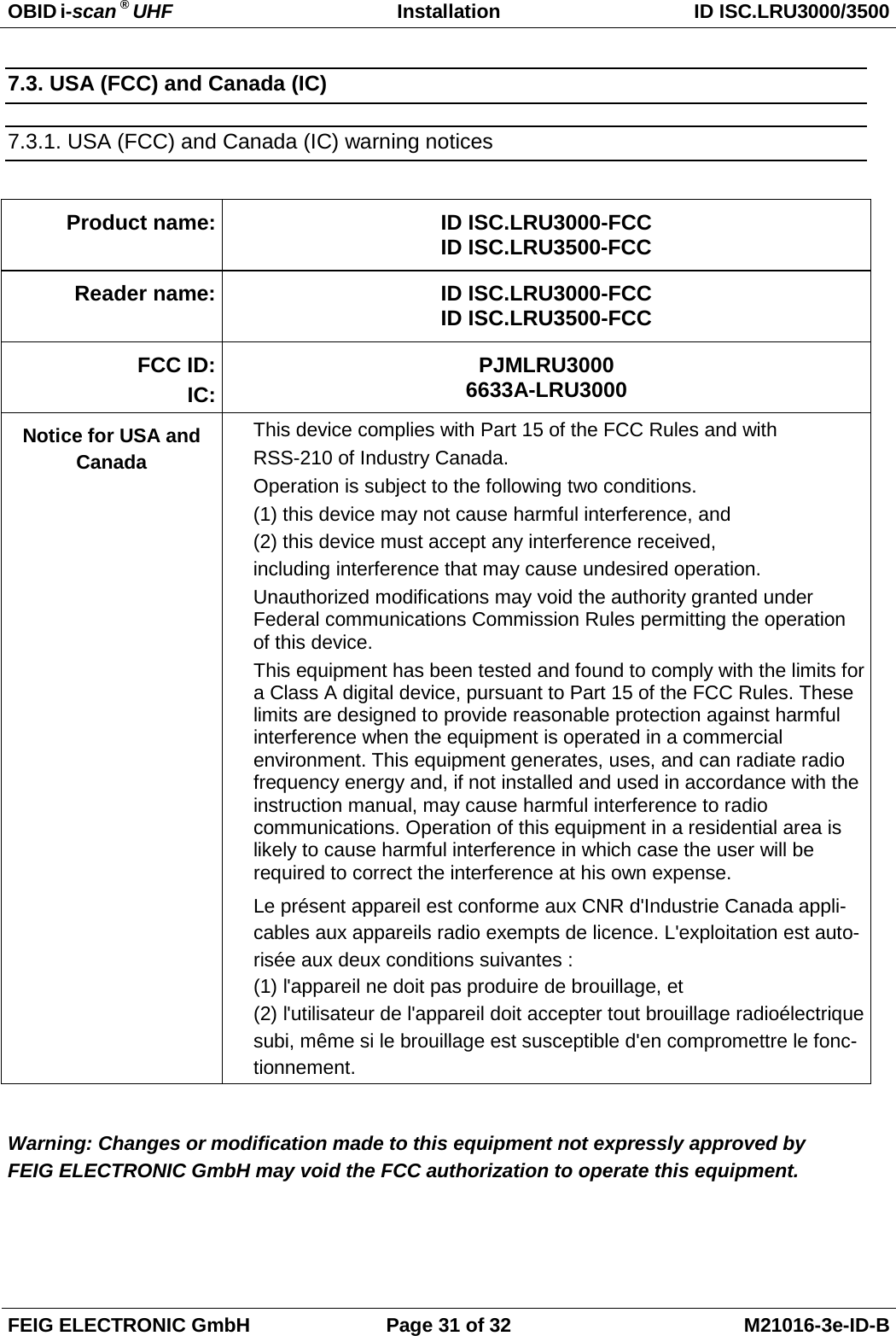
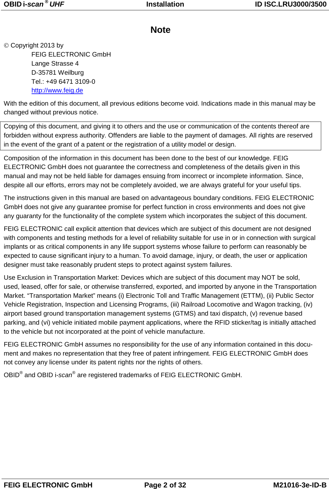
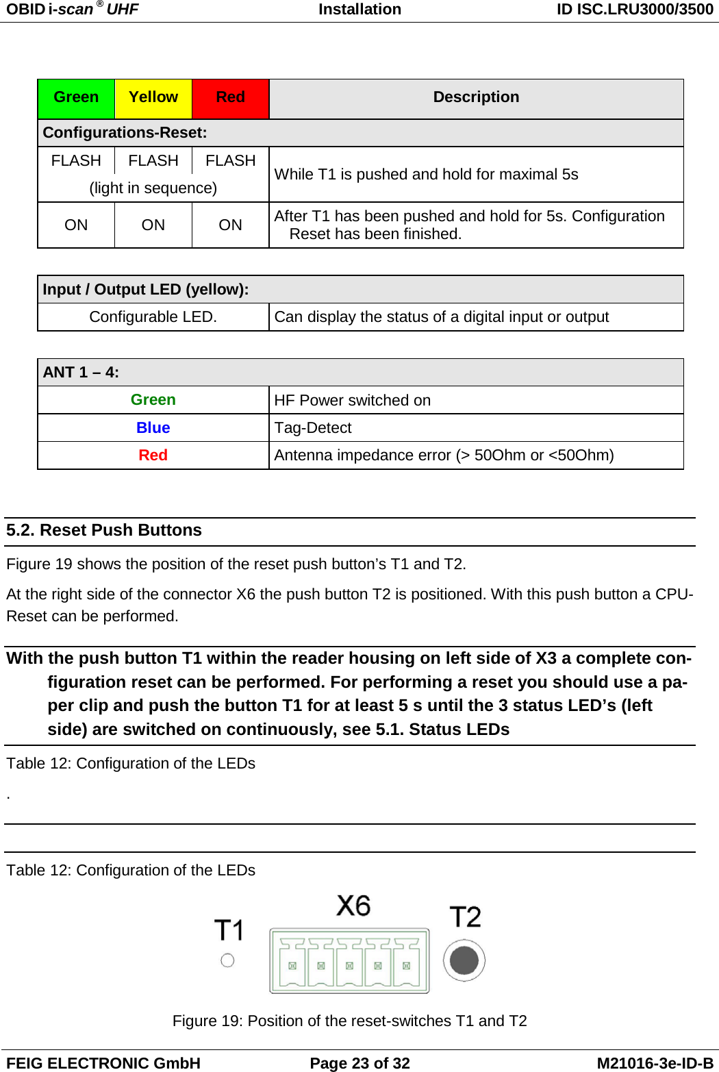
![OBID i-scan ® UHF Installation ID ISC.LRU3000/3500 FEIG ELECTRONIC GmbH Page 22 of 32 M21016-3e-ID-B 5. Operating and Display Elements 5.1. Status LEDs Table 12: Configuration of the LEDs Green Yellow Red Description ON OFF ON Boot sequence (ca.10s) after power on FLASH OFF OFF Normal Reader operation (without Host communication) FLASH BLINKT OFF Reader receives a valid protocol from host FLASH OFF ON RF Warning [0x84] (without host communication) FLASH (alternat-ing) OFF FLASH (alternat-ing) Firmware Activation necessary [0x17] / Wrong Firmware [0x18] FLASH (synchro-nous) OFF FLASH (synchro-nous) RFC Hardware Error [0xF1] OFF FLASH (synchro-nous) FLASH (synchro-nous) Hardware Warning (ACC EEPROM Error / RFC not detected) FLASH OFF FLASH (fast) USB Host Error Firmware Update: FLASH FLASH FLASH Firmware transfer from host to reader (Please do not switch off the reader or disconnect the interface cable) (light in sequence) FLASH FLASH FLASH Firmware flash into EEPROM. (Please do not switch off the reader or disconnect the interface cable) synchronous ANT 1- 4 RUN Host Communication Warning Input Output](https://usermanual.wiki/Feig-Electronic/LRU3000.UM/User-Guide-2177331-Page-23.png)
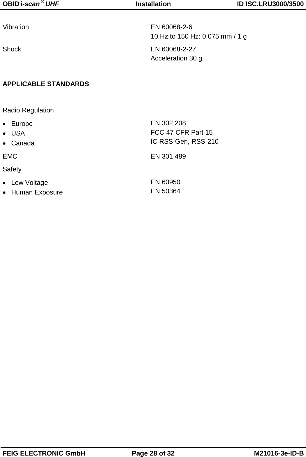
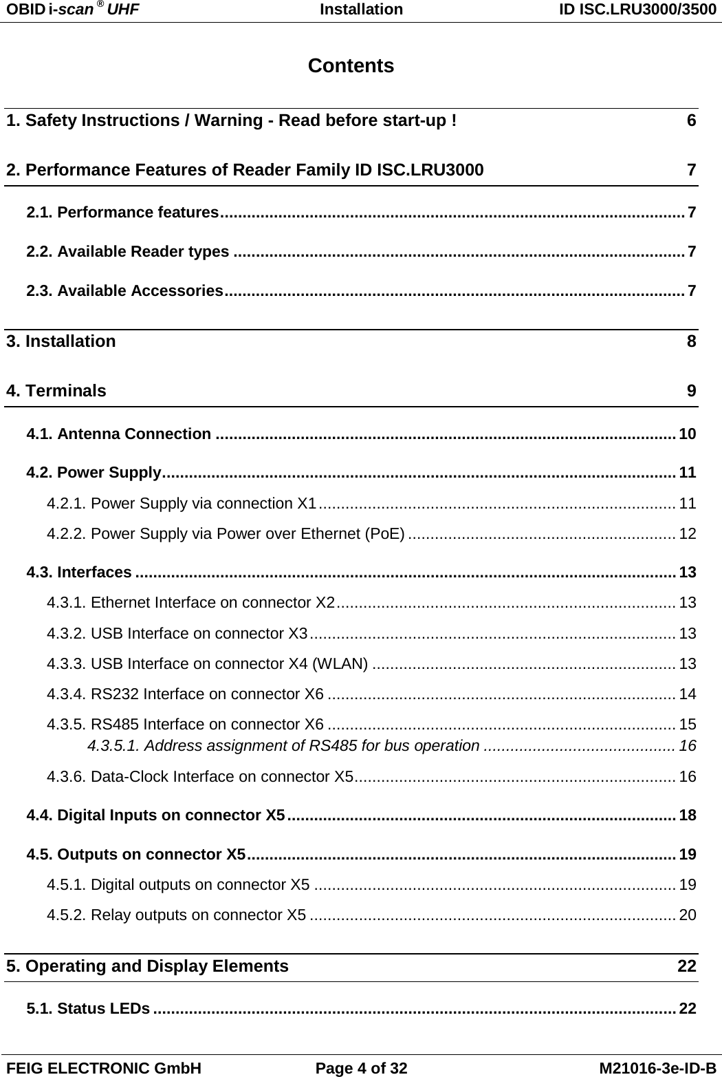
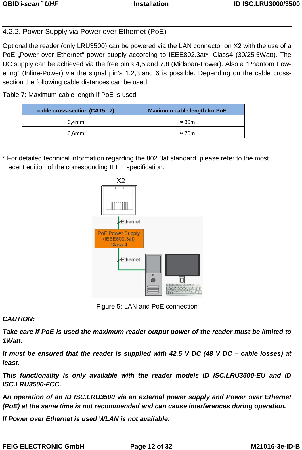
![OBID i-scan ® UHF Installation ID ISC.LRU3000/3500 FEIG ELECTRONIC GmbH Page 24 of 32 M21016-3e-ID-B 5.3. Reader Power adjustment To achieve the optimum reading performance it is necessary to set the reader output power to the highest allowed value. This depends on the used reader type (EU / FCC) and the regulation in the country were the reader is used. 5.3.1. EU-Reader according to EN302 208 According to the standard EN302 208 the maximum radiated power is 2 W e.r.p. (Effective Radiat-ed Power) in countries of the European Union. The in the reader configured output power Pout de-pends on the antenna gain in dBi and the attenuation of the antenna cable. If a circular polarized antenna is used the antenna gain [dBic] can be reduced by 3dB. At a linear polarized antenna the maximum linear antenna gain [dBi] must be used. POut = Perp - Antenna Gain + Cable loss + 2,1dB** ** Correction Factor to convert the radiated power from e.r.p to e.i.r.p. For the calculation of the reader output power POut an Excel file „Calc-RF-Power.xls“ can be used. Available from Feig Electronic GmbH. Example: ** linear antenna = „0“, circular antenna = „1“ Figure 20: Calculation of the output power In Figure 20 the allowed antenna power is shown for the use of the FEIG standard antenna ANT.U600/270 –EU and a 6m long Belden H155 coaxial cable.](https://usermanual.wiki/Feig-Electronic/LRU3000.UM/User-Guide-2177331-Page-25.png)
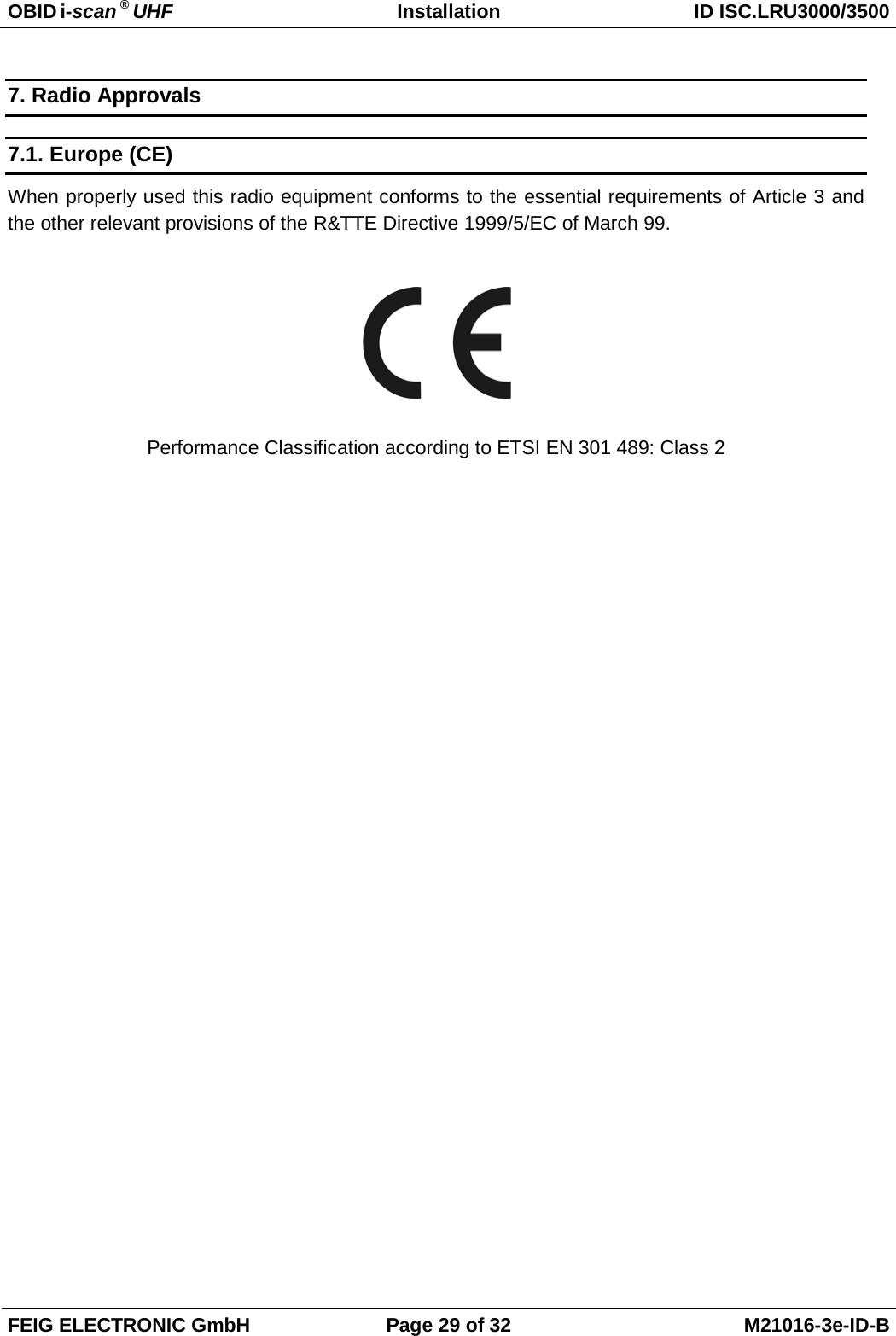
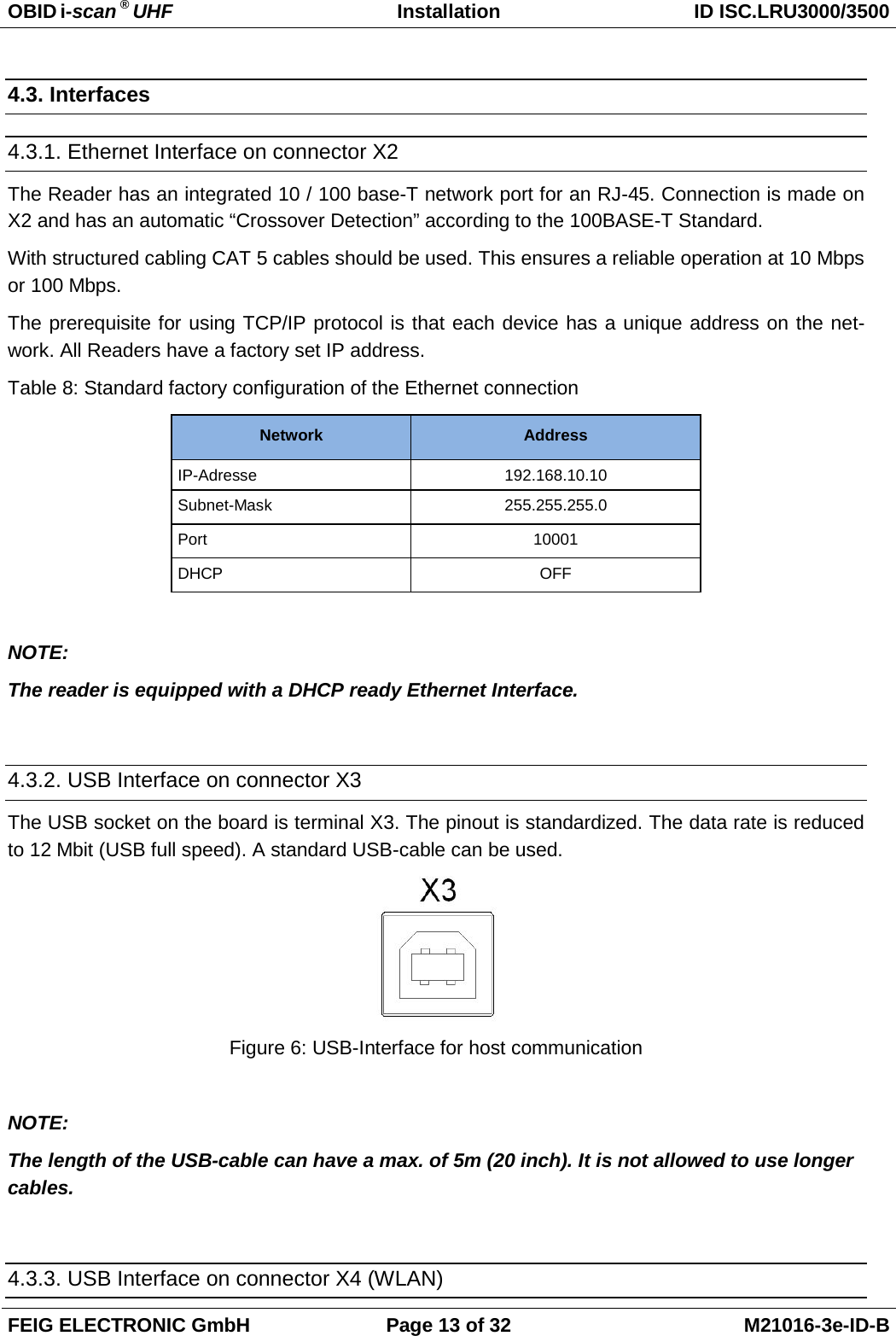
![OBID i-scan ® UHF Installation ID ISC.LRU3000/3500 FEIG ELECTRONIC GmbH Page 25 of 32 M21016-3e-ID-B 5.3.2. FCC-Reader according to FCC 47 Part 15 According to the FCC approval, Title 47, Part15 the maximum output power of the reader is limited to 1 W (30dBm). The maximum radiated power of the antenna should not increase more then 4 W e.i.r.p. Due to these facts two different cases have to be considered: If a linear polarized antenna is used which gain is less then 6 dBi (factor 4), or if a circular polarized antenna is used which gain is less then 9dBic the reader can always be configured to an output power of 1W. Antenna Gain < 6dBi → Pout = 1 W This would be the case if the FEIG standard antennas ANT.U170/170 -FCC (4dBic) or ANT.U270/270 -FCC (8,7dBic) are used. If an antenna is used which gain is more then 6dBi (9dBic) it is necessary to consider the antenna gain and the attenuation of the antenna cable to calculate the right output power. If a circular polar-ized antenna is used the antenna gain [G]=dBic can be reduced by 3dB. This is the case if the FEIG standard antenna ANT.U600/270 -FCC is used. In this configuration the maximum output power of the reader can be calculated in the following way. POut = 36 dBm (4 W e.i.r.p) – Antenna Gain (in dBi) + Cable Loss (in dB) POut = 36 dBm (4 W e.i.r.p) – Antenna Gain (in dBic) – 3 dB + Cable Loss (in dB) The antenna gain of the circular polarized standard antenna ANT.U600/270 is 10,5 dBic. This could be compared with a gain of 7,5 dBi of a linear polarized antenna (10,5 dBic – 3 dB). Example 1: Antenna ANT.U600/270 and 2 m Belden H155 Coaxial Cable: Pout= 36 dBm – 10,5 dBic + 3 dB + 0,6 dB Pout= 36 dBm – 7,5 dBi + 0,6 dB Pout= 29,1 dBm Reader Configuration = 0,8 Watt Example 2: Antenna ANT.U600/270 and 6m Belden H155 Coaxial Cable: Pout= 36 dBm – 10,5 dBic + 3 dB + 1,8 dB Pout= 36 dBm – 7,5 dBi + 1,8 dB Pout= 30,3 dBm Reader Configuration = 1,0 Watt According to Example 2 it will only be necessary to adapt the output power of the reader when the antenna ANT.U600/270 is used if the length of the antenna cable is less then 6m.](https://usermanual.wiki/Feig-Electronic/LRU3000.UM/User-Guide-2177331-Page-26.png)