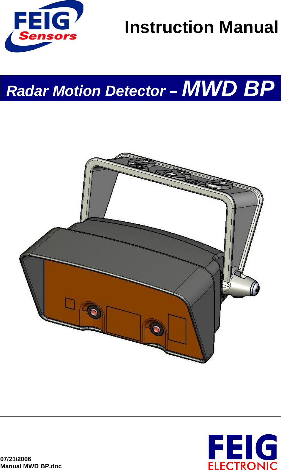
Feig Electronic MWDBP Motion Detector User Manual Manual MWD BP

Feig Electronic GmbH Motion Detector Manual MWD BP

User Manual

Instruction Manual07/21/2006Manual MWD BP.docRadar Motion Detector – MWD BP
Instruction Manual Radar Motion Detector MWD BP 2/13Manual MWD BP.doc as 07/21/2006 FEIG ELECTRONIC GmbHGeneral© Copyright 2006 by FEIG ELECTRONIC GmbHLange Straße 435781 WeilburgGermanyThe indications made in these operating instructions may be altered without previous notice.With the edition of these instructions, all previous editions become void.Composition of the information given in this manual has been done to the best of our knowledge. FEIG ELEC-TRONIC does not guarantee the correctness of the details given in these instructions and may not be held liablefor damages ensuing from incorrect installation.Since, despite of all our efforts, errors may not be completely avoided, we are always grateful for your useful tips.The installation instructions given in this manual are based on advantageous boundary conditions. FEIG ELEC-TRONIC does not give any guarantee promise for perfect function of the traffic detector in a cross surrounding.Copy or reproduction of these instructions, even if only partial, as well as translation into other languages is for-bidden unless a written consent has been granted by FEIG ELECTRONIC. This also applies to the complete orpartial storage of these operating instructions on modern input- and output media for further processing in dataprocessing systems.Please read the operating- and safety  instructions  thoroughly before putting the motion detector into opera-tion !
Instruction Manual Radar Motion Detector MWD BP 3/13Manual MWD BP.doc as 07/21/2006 FEIG ELECTRONIC GmbHContents1 Functional description____________________________________42 Installation _____________________________________________52.1 Place of installation _________________________________________________________ 52.2 Hints for planning and installation:____________________________________________ 53 Parameter Entry _________________________________________63.1 Open Parameter Entry ______________________________________________________ 63.2 Change Parameter__________________________________________________________ 63.3 Close Parameter Entry ______________________________________________________ 73.4 Show Service Parameter_____________________________________________________ 74 Standard Parameter List __________________________________85 Service Parameter List____________________________________96 Profiles ________________________________________________97 Notes _________________________________________________108 Connections ___________________________________________109 Technical data _________________________________________1010 Type Approval _________________________________________1110.1 Europe (CE)______________________________________________________________ 1110.2 USA (FCC) / Canada (IC)___________________________________________________ 1211 Safety instructions______________________________________13
Instruction Manual Radar Motion Detector MWD BP 4/13Manual MWD BP.doc as 07/21/2006 FEIG ELECTRONIC GmbH1 Functional descriptionThe MWD BP is a radar motion detector with direction identification, which has been especially designed forapplications in the area of industrial gate- and barrier systems. In some cases, the operational parameters may alsobe adjusted with an infrared remote control.Motion detection is done according to the Doppler’s principle. The sensor sends out 24 GHz microwaves. Thesemicrowaves are reflected by objects in motion and thus their frequency changes. The sensor receives these alteredfrequencies and analyses them. Thus, each motion within the detection range is recorded, analyzed by a logic andtransmitted to the gate- resp. barrier control by connecting potential-free change-over contacts.Range of application:Entry-/access recognition for the drive of industrial gate- and barrier systemsSpecial features:• Insensitive to fluctuations of temperature and humidity• Distinction vehicles/persons• Suppression of cross traffic• Object tracking for slow objects• Reversible and cutoff direction logic• Adjustable sensitivity• Application specific parameter profiles• Two channel with individual parameter setting• Two potential-free relay contacts• Large supply voltage range - AC or DC• Adjustment of operational parameters by key buttons or infrared remote control and 7-segment display• Compact plastic housing• IP 65 housing• Easy and fast installation with mounting bracket
Instruction Manual Radar Motion Detector MWD BP 5/13Manual MWD BP.doc as 07/21/2006 FEIG ELECTRONIC GmbH2 Installation2.1  Place of installationThe device is centrally mounted above the area to be monitored. Both wall- and ceiling mounting are possible. Themaximum mounting height is 7m.2.2  Hints for planning and installation:• The device has to be mounted vibrationless.• In order to avoid incorrect release, there must not be any objects in motion within the radiation field.• There must not be any fluorescent tubes within the radiation field of the detector.• It should be avoided that the radiation fields of two motion detectors overlap, since this may lead to incorrectreleases.• Do not install behind objects, building coverings or elements.• If the motion detector is exposed to rain or snow, it should be adjusted to directional recognition.• If conductive floors are used and the radiation direction is almost vertical, incorrect releases may be causedby reflections.
Instruction Manual Radar Motion Detector MWD BP 6/13Manual MWD BP.doc as 07/21/2006 FEIG ELECTRONIC GmbH3 Parameter Entry3.1  Open Parameter Entrya) Remote Control MWD RCSymbol Key Key-press Description Action DisplayExample1. ii-Button short Channel 1: displayed addressChannel 2: displayed address + 1 Actual device address is displayedwith blinking digit and decimal point Ñ1.Ò2a. 1..4  value 1..4 short Direct confirmationof device address Display first parameter name L.orVolume + 2.2b. Volume - short Select address value Increment or decrement value.Changed values doesn’t blink ! F3b. On/Off short Indirect confirmationof device address Display first parameter name L.b) Buttons on Motion Detector MWD BPThe left button is functionally assigned to the On/Off-button   on remote control MWD RC.Right button is equivalent to the Volume +- button  .Key Key-press Description Action DisplayExample1. Right or Left short Channel 1: displayed addressChannel 2: displayed address + 1 Actual device address is displayedwith blinking digit and decimal point Ñ1.Ò2. Right short Select address value Increment or decrement value.Changed values doesn’t blink ! 2.3. Left short Confirmationof device address Display first parameter name L.3.2 Change ParameterBefore changing parameter values you have to open the parameter entry as described above.a) Remote Control MWD RCSymbol Key Key-press Description Action DisplayExampleVolume + d.1. Volume -short(long)Change parameter name(long: quick selection)Display parameter name with char-acter and decimal point. P.2. On/Off short Return to displayparameter value Actual parameter value is displayedwithout decimal point. 1Volume + 2.Ò3. Volume -short(long)Change parameter value(long: quick selection)Display changed parameter valuewith blinking decimal point. 0.Ò4a. On/Off short Undo changes Display actual parameter value again(without decimal point) 1or4b. On/Off long Save new parameter value Decimal point expires after success-ful saving. 25. On/Off short Return to displayparameter name Display parameter name with char-acter and decimal point. d.
Instruction Manual Radar Motion Detector MWD BP 7/13Manual MWD BP.doc as 07/21/2006 FEIG ELECTRONIC GmbHb) Buttons on Motion Detector MWD BPKey Key-press Description Action DisplayExample1. Right short(long) Change parameter name(long: quick selection) Display parameter name with char-acter and decimal point. d.2. Left short Return to displayactual parameter value Actual parameter value is displayedwithout decimal point. 13. Right short(long) Change parameter value(long: quick selection) Display changed parameter valuewith blinking decimal point. 2.Ò4a. Left short Undo changes Display actual parameter value again(without decimal point). 1or4b. Left long Save new parameter value Decimal point expires after success-ful saving. 25. Left short Return to displayparameter name Display parameter name with char-acter and decimal point. d.3.3  Close Parameter Entrya) Remote Control MWD RCSymbol Key Key-press Description Action DisplayExample1. On/Off long Close parameter entryfrom standard parameter menuservice parameter menu display offb) Button on Motion Detector MWD BPKey Key-press Description Action DisplayExample1. Left long Close parameter entryfrom standard parameter menuservice parameter menu display offc) automatic60 s after last keypress on the remote control or directly on the motion detector parameter entry is closed automati-cally.3.4  Show Service ParameterTo display the Service Parameter you have first to open the parameter entry as described in chapter 3.1.Service Parameter names are displayed with blinking character and static decimal point.Menu navigation is conform to the navigation of standard parameter.a) Remote Control MWD RCSymbol Key Key-press Description Action DisplayExample1. F+ or F- - long Activate service parameter from standard parameter menu Display first service parameter name ÑA.b) Button on Motion Detector MWD BPThe left button is functionally assigned to the On/Off-button on remote control MWD RC.The right button is equivalent to the Volume +- button.Button Key-press Description Action DisplayExample1. Left and Right long Activate service parameter from standard parameter menu Display first service parameter name ÑA.
Instruction Manual Radar Motion Detector MWD BP 8/13Manual MWD BP.doc as 07/21/2006 FEIG ELECTRONIC GmbH4  Standard Parameter List7-Segment DisplayParameter Name ParameterName Value Range Parameter DefinitionSensitivity Level L. 1..9,A..F1 = low:7 = middle:9 *:F = highdirection d. 0..20 = off1 = approaching *2 = departurehuman detection h. 0..30 = off *1 = low:3 = highvehicle detection u. 0..30 = off *1 = low:3 = highCross traffic suppression C. 0..30 = off *1 = low:3 = high Object tracking O. 0..30 = off *1 = low:3 = highrelay function r. 0..40 = off1 = channel 1 *  (for channel 1)2 = channel 2 *  (for channel 2)3 = channel 1 OR channel 24 = channel 1 AND channel 2output on delay time t. 0..F0 = 0s *1..F = 0.2s .. 3.0s (value x 0.2s)output off delay Time T. 0..F0 = 0s1 = 0.2s  (value x 0.2s)2 = 0.4s *3..F = 0.6s .. 3.0srelay operating mode o. 0..10 = normally de-energized *1 = normally energizedProfiles P. 0..90 = parameter changed after profile setting (only displayed !)1 = Profile No 1:  initiate Factory Setting *2..9 = Profile No. 2..9* factory settingNote:Resetting to factory values can be effected by parameter name “profile” with parameter value “1”. Alternativelypress both keys while switching power supply on.
Instruction Manual Radar Motion Detector MWD BP 9/13Manual MWD BP.doc as 07/21/2006 FEIG ELECTRONIC GmbH5 Service Parameter List7-Segment DisplayParameter ParameterName Value Range Parameter Definitiondevice Address A. 1..9,b..d1 = 1 *:                                          (only odd address)d = 13miscellaneous Settings S. 0..30 = all off **1 = key operation on, display relay output off2 = only display relay status off **3 = key operation and display relay output on * firmware information i. -show Firmware-Version on display:- manually, with „ “-Button for each character- automatically, with „i“-Button one character per second* factory setting** Key operation is always available in the first 15 minutes after power on regardless of  the parameter setting. If the display of the relayoutput is deactivated, only the decimal point is commonly used to show the relay status of both channels.6 ProfilesProfile No. 1234 56789Channel 1 2 1 2 1 2 1 21212121212SensitivityLevel 999999999Direction appr. appr. appr. appr. appr. appr. appr. appr. appr.HumanDetection - - - = 2- - - = 2- - -VehicleDetection - - --= 2- --= 2- -CrossTrafficSuppr. - - - - -= 2- - -= 2-DetectionObjectTracking - - - - --= 2- --= 2On delay ---------Off delay 400 ms 400 ms 400 ms 400 ms 400 ms 400 ms 400 ms 400 ms 400 msAssign-ments(Logic) Ch1 Ch2 Ch1 - Ch1 Ch2 Ch1 Ch2 Ch1 Ch2 Ch1 Ch2 Ch1 Ch2 Ch1 Ch2 Ch1 Ch2RelayWorkingPrinciple AP AP AP AP AP AP RP RP RPRemarksFactorySetting:additionalparameter(e.g. deviceaddress =1)will beinitializedtoo.Channel 2:Relay outputoffsame asFactorySettingwithoutinitializingadditionalparameterChannel 1 :only personsChannel 2 :only vehiclesChannel 1 :all objectsChannel 2 :cross trafficsuppressionChannel 1 :all objectsChannel 2 :slow motionobjecttrackingProfile No. 4,but with RPProfile No. 5,but with RPProfile No. 6,but with RPCh1  = Channel 1 Ch2  = Channel 2AP  = normally de-energized RP  = normally energized appr.  = approaching direction
Instruction Manual Radar Motion Detector MWD BP 10/13Manual MWD BP.doc as 07/21/2006 FEIG ELECTRONIC GmbH7 Notes- The MWD BP is a 2 channel device. While opening parameter entry first the odd address used to open chan-nel 1 will displayed. The following even device address activates channel 2.- In factory settings relay 1 with change over contacts is assigned to channel 1 (display „| .“) and relay 2 withnormally open contact is assigned to channel 2 (display „| |.“). It is possible to change relay assignments viaparameter entry.- Only the odd device address of channel 1 can be changed. The address of channel 2 results from the followingeven address.- Common parameter (e.g. firmware info, profiles...) can be displayed/changed with even or odd device ad-dress.8 ConnectionsX18NC1Com1NO1GND 24V NO2Com21234567Backside view, Contact status for power off9 Technical dataDimensions 135x65x130mm (BxHxT)Protective system IP 65Power supply 12-27 V AC / 12-30 V DCPower consumption typ. 1,0 W, max. 2,4 WAdmissible working temperature -20 °C .. +60 °CStoring temperature -30 °C .. +75 °CAir moisture < 95 % not condensingTransmit frequency typ. 24,125 GHzOutput power (EIRP) typ. 40 mW, max. 100 mWOutput relaymax. switching load 1 A / 30 V AC/DC (resistive load)min. switching load 1 mA / 5 V DCUse external protective wiring for inductive load !Maximum mounting height 7 m
Instruction Manual Radar Motion Detector MWD BP 11/13Manual MWD BP.doc as 07/21/2006 FEIG ELECTRONIC GmbH10 Type  Approval10.1 Europe (CE)When used according to regulation, this radio equipment conforms with the basic requirements of article 3 and theother relevant provisions of the R&TTE guideline1999/5/EC dated March 99.
Instruction Manual Radar Motion Detector MWD BP 12/13Manual MWD BP.doc as 07/21/2006 FEIG ELECTRONIC GmbH10.2  USA (FCC) / Canada (IC)FCC ID:  PJMMWDBPIC:  6633A-MWDBPThis device complies with part 15 of the FCC Rules and with RSS-210 of Industry Canada.Operation is subject to the following two conditions:(1)  This device may not cause harmful interference, and(2)  this device must accept any interference received, including interference that may  cause undesired operation.Warning: Changes or modifications made to this equipment not expressly approved by FEIG ELECTRONICGmbH may void the FCC authorization to operate this equipment.This equipment has been tested and found to comply with the limits for a Class B digital device, pursuant to Part15 of the FCC Rules. These limits are designed to provide reasonable protection against harmful interference in aresidential installation. This equipment generates, uses and can radiate radio frequency energy and, if not installedand used in accordance with the instructions, may cause harmful interference to radio communications. However,there is no guarantee that interference will not occur in a particular installation. If this equipment does causeharmful interference to radio or television reception, which can be determined by turning the equipment off andon, the user is encouraged to try to correct the interference by one or more of the following measures:• Reorient or relocate the receiving antenna.• Increase the separation between the equipment and receiver.• Connect the equipment into an outlet on a circuit different from that to which the receiver is connected.• Consult the dealer or an experienced radio/TV technician for help.
Instruction Manual Radar Motion Detector MWD BP 13/13Manual MWD BP.doc as 07/21/2006 FEIG ELECTRONIC GmbH11 Safety  instructions• This device shall only be used for the purpose intended by the manufacturer.• The operating instructions have to be  handed out to each user and accessible at any time.• Improper changes and spare parts resp. special features which are not sold or recommended by the manufac-turer of the device may cause fires, electric shock and injuries. Such measures therefore lead to nonliability ofthe manufacturer and no guarantee will be given.• For this device, the indemnity contract applies in the version valid at the time of purchase. We exclude liabil-ity for improper or wrong manual or automatic adjustment of parameters resp. improper use of the appliance.• Repair work should only be carried out by the manufacturer.• Connection, initiation, maintenance, measuring and adjustment of the motion detector should only be carriedout by electrical engineers with accident prevention skills.• When handling appliances which get into contact with electric current, VDE-rules have to be observed - espe-cially VDE 0100, VDE 0550/0551, VDE 0700, VDE 0711, VDE 0860, VDE 0105 as well as the fire – andaccident prevention standard VBG4.• Please switch off current supply prior to opening the device and make sure that it remains off.• If an indicator lamp goes out, this is not a proof that the device is without electricity and disconnected frompower supply. All work that is carried out at the device as well as installation has to be carried out in confor-mance with the national electric regulations and the local rules.• The user has to make sure that the appliance is mounted and connected according to the technical rules of thecountry of  installation as well as other regional regulations. This applies especially to cable dimensioning,protection, earthing, cutoff, disconnection, isolation supervision and excess current cut-out.• Low-voltage operation is not allowed at the relay outputs.• According to machine rule 89/392/EWG, appendix IV, the device may not be used as a safety component. Infacilities with a high danger potential, additional safety devices are necessary !• The hard gold alloy of the relay contacts is destroyed if switching currents of more than 100 mA are used.Relays with such pre-damaged contacts may only switch currents of more than 100 mA reliably!• If the place of operation is located in direct proximity to foil gates, suitable measures have to be taken tobranch off the electrostatic charging of the gate foil.

Navigation menu