Feig Electronic MWDBP Motion Detector User Manual Manual MWD BP
Feig Electronic GmbH Motion Detector Manual MWD BP
User Manual
Instruction Manual
07/21/2006
Manual MWD BP.doc
Radar Motion Detector – MWD BP

Instruction Manual Radar Motion Detector MWD BP 2/13
Manual MWD BP.doc as 07/21/2006 FEIG ELECTRONIC GmbH
General
© Copyright 2006 by FEIG ELECTRONIC GmbH
Lange Straße 4
35781 Weilburg
Germany
The indications made in these operating instructions may be altered without previous notice.
With the edition of these instructions, all previous editions become void.
Composition of the information given in this manual has been done to the best of our knowledge. FEIG ELEC-
TRONIC does not guarantee the correctness of the details given in these instructions and may not be held liable
for damages ensuing from incorrect installation.
Since, despite of all our efforts, errors may not be completely avoided, we are always grateful for your useful tips.
The installation instructions given in this manual are based on advantageous boundary conditions. FEIG ELEC-
TRONIC does not give any guarantee promise for perfect function of the traffic detector in a cross surrounding.
Copy or reproduction of these instructions, even if only partial, as well as translation into other languages is for-
bidden unless a written consent has been granted by FEIG ELECTRONIC. This also applies to the complete or
partial storage of these operating instructions on modern input- and output media for further processing in data
processing systems.
Please read the operating- and safety instructions thoroughly before putting the motion detector into opera-
tion !

Instruction Manual Radar Motion Detector MWD BP 3/13
Manual MWD BP.doc as 07/21/2006 FEIG ELECTRONIC GmbH
Contents
1 Functional description____________________________________4
2 Installation _____________________________________________5
2.1 Place of installation _________________________________________________________ 5
2.2 Hints for planning and installation:____________________________________________ 5
3 Parameter Entry _________________________________________6
3.1 Open Parameter Entry ______________________________________________________ 6
3.2 Change Parameter__________________________________________________________ 6
3.3 Close Parameter Entry ______________________________________________________ 7
3.4 Show Service Parameter_____________________________________________________ 7
4 Standard Parameter List __________________________________8
5 Service Parameter List____________________________________9
6 Profiles ________________________________________________9
7 Notes _________________________________________________10
8 Connections ___________________________________________10
9 Technical data _________________________________________10
10 Type Approval _________________________________________11
10.1 Europe (CE)______________________________________________________________ 11
10.2 USA (FCC) / Canada (IC)___________________________________________________ 12
11 Safety instructions______________________________________13

Instruction Manual Radar Motion Detector MWD BP 4/13
Manual MWD BP.doc as 07/21/2006 FEIG ELECTRONIC GmbH
1 Functional description
The MWD BP is a radar motion detector with direction identification, which has been especially designed for
applications in the area of industrial gate- and barrier systems. In some cases, the operational parameters may also
be adjusted with an infrared remote control.
Motion detection is done according to the Doppler’s principle. The sensor sends out 24 GHz microwaves. These
microwaves are reflected by objects in motion and thus their frequency changes. The sensor receives these altered
frequencies and analyses them. Thus, each motion within the detection range is recorded, analyzed by a logic and
transmitted to the gate- resp. barrier control by connecting potential-free change-over contacts.
Range of application:
Entry-/access recognition for the drive of industrial gate- and barrier systems
Special features:
• Insensitive to fluctuations of temperature and humidity
• Distinction vehicles/persons
• Suppression of cross traffic
• Object tracking for slow objects
• Reversible and cutoff direction logic
• Adjustable sensitivity
• Application specific parameter profiles
• Two channel with individual parameter setting
• Two potential-free relay contacts
• Large supply voltage range - AC or DC
• Adjustment of operational parameters by key buttons or infrared remote control and 7-segment display
• Compact plastic housing
• IP 65 housing
• Easy and fast installation with mounting bracket

Instruction Manual Radar Motion Detector MWD BP 5/13
Manual MWD BP.doc as 07/21/2006 FEIG ELECTRONIC GmbH
2 Installation
2.1 Place of installation
The device is centrally mounted above the area to be monitored. Both wall- and ceiling mounting are possible. The
maximum mounting height is 7m.
2.2 Hints for planning and installation:
• The device has to be mounted vibrationless.
• In order to avoid incorrect release, there must not be any objects in motion within the radiation field.
• There must not be any fluorescent tubes within the radiation field of the detector.
• It should be avoided that the radiation fields of two motion detectors overlap, since this may lead to incorrect
releases.
• Do not install behind objects, building coverings or elements.
• If the motion detector is exposed to rain or snow, it should be adjusted to directional recognition.
• If conductive floors are used and the radiation direction is almost vertical, incorrect releases may be caused
by reflections.
Instruction Manual Radar Motion Detector MWD BP 6/13
Manual MWD BP.doc as 07/21/2006 FEIG ELECTRONIC GmbH
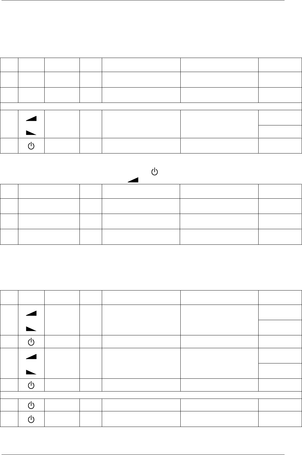
3 Parameter Entry
3.1 Open Parameter Entry
a) Remote Control MWD RC
Symbol Key Key-
press Description Action Display
Example
1. ii-Button short Channel 1: displayed address
Channel 2: displayed address + 1 Actual device address is displayed
with blinking digit and decimal point Ñ1.Ò
2a. 1..4 value 1..4 short Direct confirmation
of device address Display first parameter name L.
or
Volume + 2.
2b. Volume - short Select address value Increment or decrement value.
Changed values doesn’t blink ! F
3b. On/Off short Indirect confirmation
of device address Display first parameter name L.
b) Buttons on Motion Detector MWD BP
The left button is functionally assigned to the On/Off-button on remote control MWD RC.
Right button is equivalent to the Volume +- button .
Key Key-
press Description Action Display
Example
1. Right or Left short Channel 1: displayed address
Channel 2: displayed address + 1 Actual device address is displayed
with blinking digit and decimal point Ñ1.Ò
2. Right short Select address value Increment or decrement value.
Changed values doesn’t blink ! 2.
3. Left short Confirmation
of device address Display first parameter name L.
3.2 Change Parameter
Before changing parameter values you have to open the parameter entry as described above.
a) Remote Control MWD RC
Symbol Key Key-
press Description Action Display
Example
Volume + d.
1. Volume -
short
(long)
Change parameter name
(long: quick selection)
Display parameter name with char-
acter and decimal point. P.
2. On/Off short Return to display
parameter value Actual parameter value is displayed
without decimal point. 1
Volume + 2.Ò
3. Volume -
short
(long)
Change parameter value
(long: quick selection)
Display changed parameter value
with blinking decimal point. 0.Ò
4a. On/Off short Undo changes Display actual parameter value again
(without decimal point) 1
or
4b. On/Off long Save new parameter value Decimal point expires after success-
ful saving. 2
5. On/Off short Return to display
parameter name Display parameter name with char-
acter and decimal point. d.

Instruction Manual Radar Motion Detector MWD BP 7/13
Manual MWD BP.doc as 07/21/2006 FEIG ELECTRONIC GmbH
b) Buttons on Motion Detector MWD BP
Key Key-
press Description Action Display
Example
1. Right short
(long) Change parameter name
(long: quick selection) Display parameter name with char-
acter and decimal point. d.
2. Left short Return to display
actual parameter value Actual parameter value is displayed
without decimal point. 1
3. Right short
(long) Change parameter value
(long: quick selection) Display changed parameter value
with blinking decimal point. 2.Ò
4a. Left short Undo changes Display actual parameter value again
(without decimal point). 1
or
4b. Left long Save new parameter value Decimal point expires after success-
ful saving. 2
5. Left short Return to display
parameter name Display parameter name with char-
acter and decimal point. d.
3.3 Close Parameter Entry
a) Remote Control MWD RC
Symbol Key Key-
press Description Action Display
Example
1. On/Off long Close parameter entry
from standard parameter menu
service parameter menu display off
b) Button on Motion Detector MWD BP
Key Key-
press Description Action Display
Example
1. Left long Close parameter entry
from standard parameter menu
service parameter menu display off
c) automatic
60 s after last keypress on the remote control or directly on the motion detector parameter entry is closed automati-
cally.
3.4 Show Service Parameter
To display the Service Parameter you have first to open the parameter entry as described in chapter 3.1.
Service Parameter names are displayed with blinking character and static decimal point.
Menu navigation is conform to the navigation of standard parameter.
a) Remote Control MWD RC
Symbol Key Key-
press Description Action Display
Example
1. F+ or F- - long Activate service parameter from
standard parameter menu Display first service parameter name ÑA.
b) Button on Motion Detector MWD BP
The left button is functionally assigned to the On/Off-button on remote control MWD RC.
The right button is equivalent to the Volume +- button.
Button Key-
press Description Action Display
Example
1. Left and Right long Activate service parameter from
standard parameter menu Display first service parameter name ÑA.

Instruction Manual Radar Motion Detector MWD BP 8/13
Manual MWD BP.doc as 07/21/2006 FEIG ELECTRONIC GmbH
4 Standard Parameter List
7-Segment Display
Parameter Name Parameter
Name Value Range Parameter Definition
Sensitivity Level L. 1..9,
A..F
1 = low
:
7 = middle
:
9 *
:
F = high
direction d. 0..20 = off
1 = approaching *
2 = departure
human detection h. 0..3
0 = off *
1 = low
:
3 = high
vehicle detection u. 0..3
0 = off *
1 = low
:
3 = high
Cross traffic suppression C. 0..3
0 = off *
1 = low
:
3 = high
Object tracking O. 0..3
0 = off *
1 = low
:
3 = high
relay function r. 0..4
0 = off
1 = channel 1 * (for channel 1)
2 = channel 2 * (for channel 2)
3 = channel 1 OR channel 2
4 = channel 1 AND channel 2
output on delay time t. 0..F0 = 0s *
1..F = 0.2s .. 3.0s (value x 0.2s)
output off delay Time T. 0..F
0 = 0s
1 = 0.2s (value x 0.2s)
2 = 0.4s *
3..F = 0.6s .. 3.0s
relay operating mode o. 0..10 = normally de-energized *
1 = normally energized
Profiles P. 0..90 = parameter changed after profile setting (only displayed !)
1 = Profile No 1: initiate Factory Setting *
2..9 = Profile No. 2..9
* factory setting
Note:
Resetting to factory values can be effected by parameter name “profile” with parameter value “1”. Alternatively
press both keys while switching power supply on.
Instruction Manual Radar Motion Detector MWD BP 9/13
Manual MWD BP.doc as 07/21/2006 FEIG ELECTRONIC GmbH
5 Service Parameter List
7-Segment Display
Parameter Parameter
Name Value Range Parameter Definition
device Address A. 1..9,
b..d
1 = 1 *
: (only odd address)
d = 13
miscellaneous Settings S. 0..3
0 = all off **
1 = key operation on, display relay output off
2 = only display relay status off **
3 = key operation and display relay output on *
firmware information i. -
show Firmware-Version on display:
- manually, with „ “-Button for each character
- automatically, with „i“-Button one character per second
* factory setting
** Key operation is always available in the first 15 minutes after power on regardless of the parameter setting. If the display of the relay
output is deactivated, only the decimal point is commonly used to show the relay status of both channels.
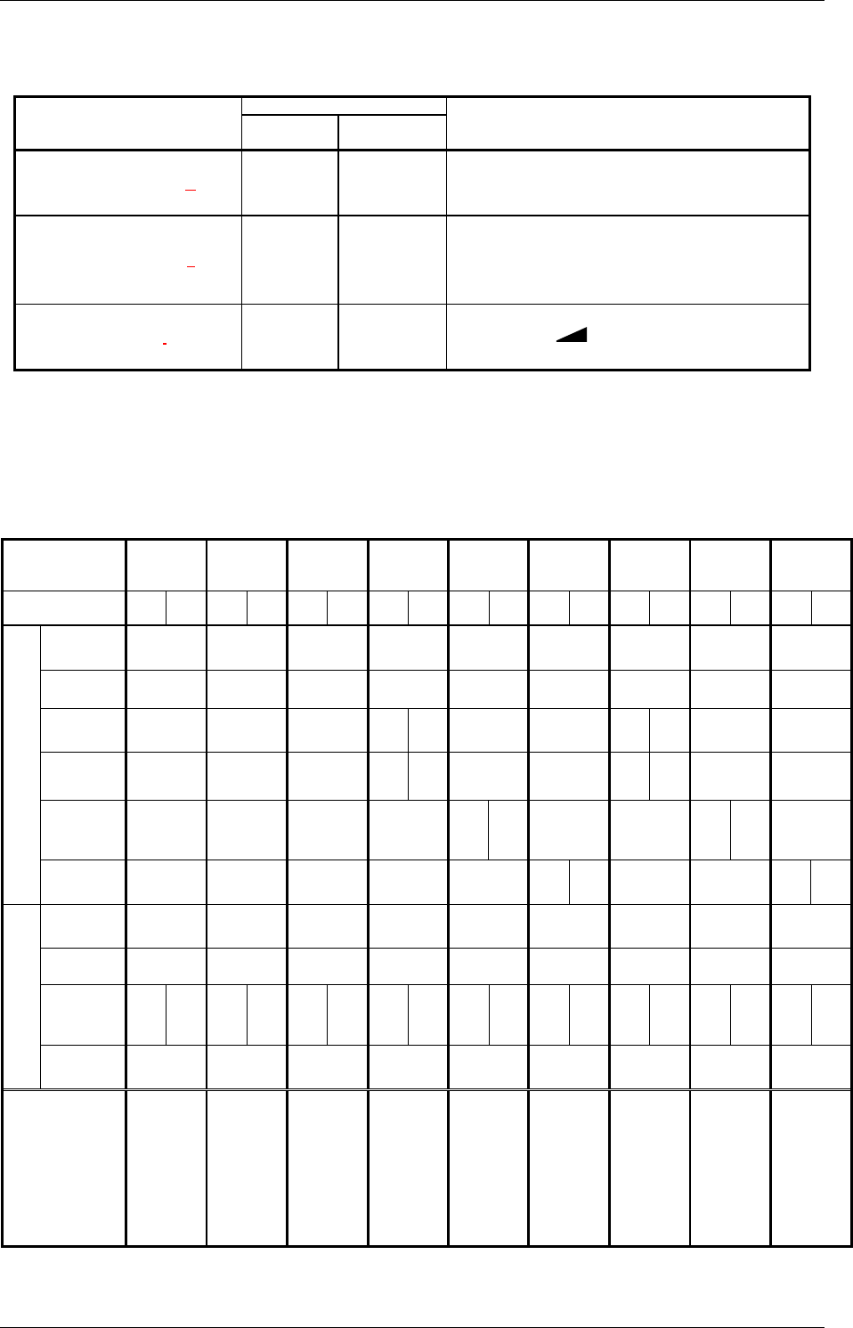
6 Profiles
Profile No. 1234 56789
Channel 1 2 1 2 1 2 1 21212121212
Sensitivity
Level 999999999
Direction appr. appr. appr. appr. appr. appr. appr. appr. appr.
Human
Detection - - - = 2- - - = 2- - -
Vehicle
Detection - - --= 2- --= 2- -
Cross
Traffic
Suppr. - - - - -= 2- - -= 2-
Detection
Object
Tracking - - - - --= 2- --= 2
On delay ---------
Off delay 400 ms 400 ms 400 ms 400 ms 400 ms 400 ms 400 ms 400 ms 400 ms
Assign-
ments
(Logic) Ch1 Ch2 Ch1 - Ch1 Ch2 Ch1 Ch2 Ch1 Ch2 Ch1 Ch2 Ch1 Ch2 Ch1 Ch2 Ch1 Ch2
Relay
Working
Principle AP AP AP AP AP AP RP RP RP
Remarks
Factory
Setting:
additional
parameter
(e.g. device
address =1)
will be
initialized
too.
Channel 2:
Relay output
off
same as
Factory
Setting
without
initializing
additional
parameter
Channel 1 :
only persons
Channel 2 :
only vehicles
Channel 1 :
all objects
Channel 2 :
cross traffic
suppression
Channel 1 :
all objects
Channel 2 :
slow motion
object
tracking
Profile No. 4,
but with RP
Profile No. 5,
but with RP
Profile No. 6,
but with RP
Ch1 = Channel 1 Ch2 = Channel 2
AP = normally de-energized RP = normally energized appr. = approaching direction
Instruction Manual Radar Motion Detector MWD BP 10/13
Manual MWD BP.doc as 07/21/2006 FEIG ELECTRONIC GmbH
7 Notes
- The MWD BP is a 2 channel device. While opening parameter entry first the odd address used to open chan-
nel 1 will displayed. The following even device address activates channel 2.
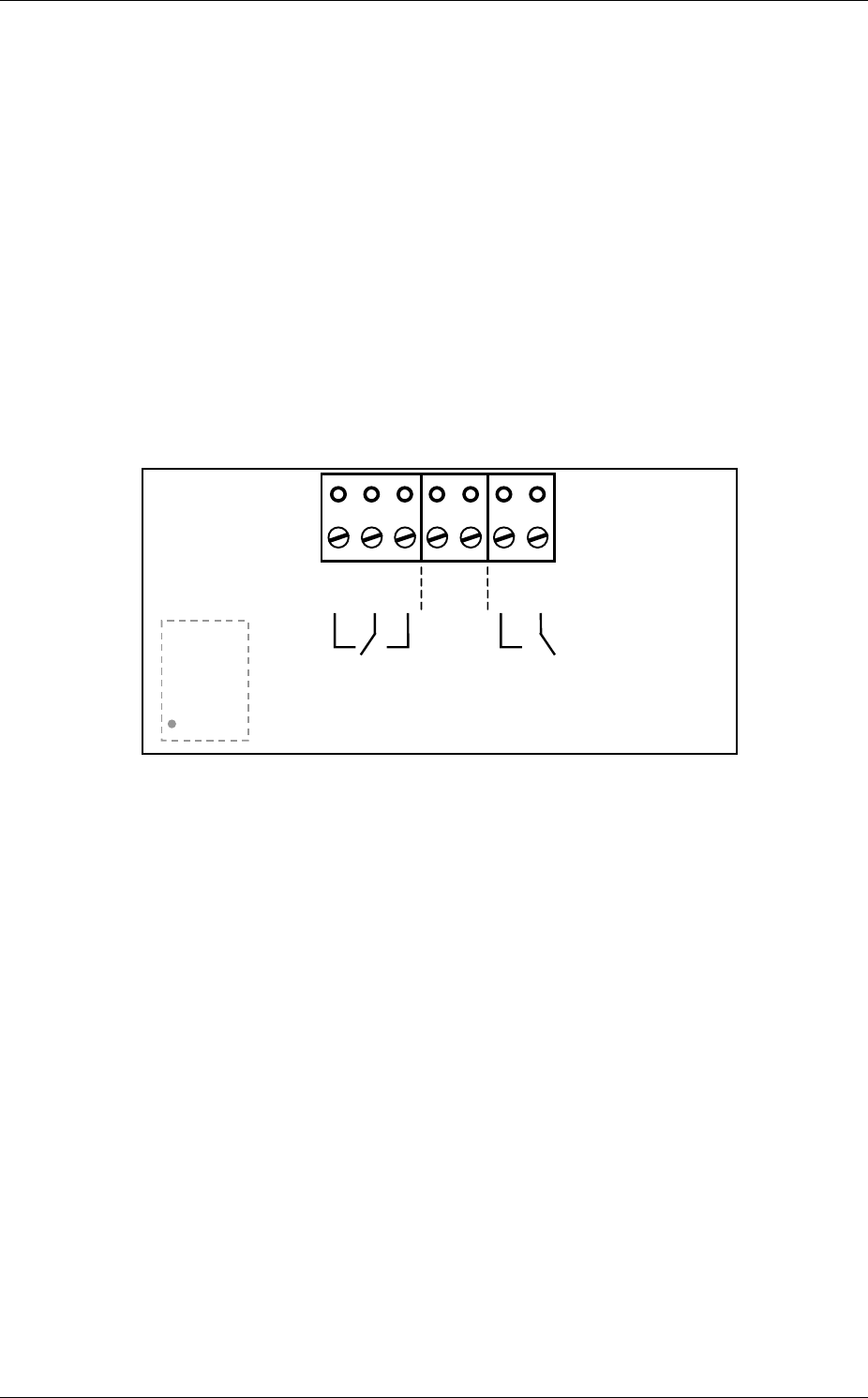
- In factory settings relay 1 with change over contacts is assigned to channel 1 (display „| .“) and relay 2 with
normally open contact is assigned to channel 2 (display „| |.“). It is possible to change relay assignments via
parameter entry.
- Only the odd device address of channel 1 can be changed. The address of channel 2 results from the following
even address.
- Common parameter (e.g. firmware info, profiles...) can be displayed/changed with even or odd device ad-
dress.
8 Connections
X1
8
NC
1Com
1NO
1GND 24V NO
2Com
2
1234567
Backside view, Contact status for power off
9 Technical data
Dimensions 135x65x130mm (BxHxT)
Protective system IP 65
Power supply 12-27 V AC / 12-30 V DC
Power consumption typ. 1,0 W, max. 2,4 W
Admissible working temperature -20 °C .. +60 °C
Storing temperature -30 °C .. +75 °C
Air moisture < 95 % not condensing
Transmit frequency typ. 24,125 GHz
Output power (EIRP) typ. 40 mW, max. 100 mW
Output relay
max. switching load 1 A / 30 V AC/DC (resistive load)
min. switching load 1 mA / 5 V DC
Use external protective wiring for inductive load !
Maximum mounting height 7 m

Instruction Manual Radar Motion Detector MWD BP 11/13
Manual MWD BP.doc as 07/21/2006 FEIG ELECTRONIC GmbH
10 Type Approval
10.1 Europe (CE)
When used according to regulation, this radio equipment conforms with the basic requirements of article 3 and the
other relevant provisions of the R&TTE guideline1999/5/EC dated March 99.

Instruction Manual Radar Motion Detector MWD BP 12/13
Manual MWD BP.doc as 07/21/2006 FEIG ELECTRONIC GmbH
10.2 USA (FCC) / Canada (IC)
FCC ID: PJMMWDBP
IC: 6633A-MWDBP
This device complies with part 15 of the FCC Rules and with RSS-210 of Industry Canada.
Operation is subject to the following two conditions:
(1) This device may not cause harmful interference, and
(2) this device must accept any interference received, including interference that may
cause undesired operation.
Warning: Changes or modifications made to this equipment not expressly approved by FEIG ELECTRONIC
GmbH may void the FCC authorization to operate this equipment.
This equipment has been tested and found to comply with the limits for a Class B digital device, pursuant to Part
15 of the FCC Rules. These limits are designed to provide reasonable protection against harmful interference in a
residential installation. This equipment generates, uses and can radiate radio frequency energy and, if not installed
and used in accordance with the instructions, may cause harmful interference to radio communications. However,
there is no guarantee that interference will not occur in a particular installation. If this equipment does cause
harmful interference to radio or television reception, which can be determined by turning the equipment off and
on, the user is encouraged to try to correct the interference by one or more of the following measures:
• Reorient or relocate the receiving antenna.
• Increase the separation between the equipment and receiver.
• Connect the equipment into an outlet on a circuit different from that to which the receiver is connected.
• Consult the dealer or an experienced radio/TV technician for help.

Instruction Manual Radar Motion Detector MWD BP 13/13
Manual MWD BP.doc as 07/21/2006 FEIG ELECTRONIC GmbH
11 Safety instructions
• This device shall only be used for the purpose intended by the manufacturer.
• The operating instructions have to be handed out to each user and accessible at any time.
• Improper changes and spare parts resp. special features which are not sold or recommended by the manufac-
turer of the device may cause fires, electric shock and injuries. Such measures therefore lead to nonliability of
the manufacturer and no guarantee will be given.
• For this device, the indemnity contract applies in the version valid at the time of purchase. We exclude liabil-
ity for improper or wrong manual or automatic adjustment of parameters resp. improper use of the appliance.
• Repair work should only be carried out by the manufacturer.
• Connection, initiation, maintenance, measuring and adjustment of the motion detector should only be carried
out by electrical engineers with accident prevention skills.
• When handling appliances which get into contact with electric current, VDE-rules have to be observed - espe-
cially VDE 0100, VDE 0550/0551, VDE 0700, VDE 0711, VDE 0860, VDE 0105 as well as the fire – and
accident prevention standard VBG4.
• Please switch off current supply prior to opening the device and make sure that it remains off.
• If an indicator lamp goes out, this is not a proof that the device is without electricity and disconnected from
power supply. All work that is carried out at the device as well as installation has to be carried out in confor-
mance with the national electric regulations and the local rules.
• The user has to make sure that the appliance is mounted and connected according to the technical rules of the
country of installation as well as other regional regulations. This applies especially to cable dimensioning,
protection, earthing, cutoff, disconnection, isolation supervision and excess current cut-out.
• Low-voltage operation is not allowed at the relay outputs.
• According to machine rule 89/392/EWG, appendix IV, the device may not be used as a safety component. In
facilities with a high danger potential, additional safety devices are necessary !
• The hard gold alloy of the relay contacts is destroyed if switching currents of more than 100 mA are used.
Relays with such pre-damaged contacts may only switch currents of more than 100 mA reliably!
• If the place of operation is located in direct proximity to foil gates, suitable measures have to be taken to
branch off the electrostatic charging of the gate foil.