Feig Electronic RW02 Inductive Reader User Manual RW02 Manual
Feig Electronic GmbH Inductive Reader RW02 Manual
UserManual.wiki
>
Feig Electronic
>
RW02 User Manual
Users Manual
Navigation menu
Upload a User Manual
Namespaces
Wiki Guide
HTML
PDF
Info
Views
User Manual
Discussion / Help
Navigation

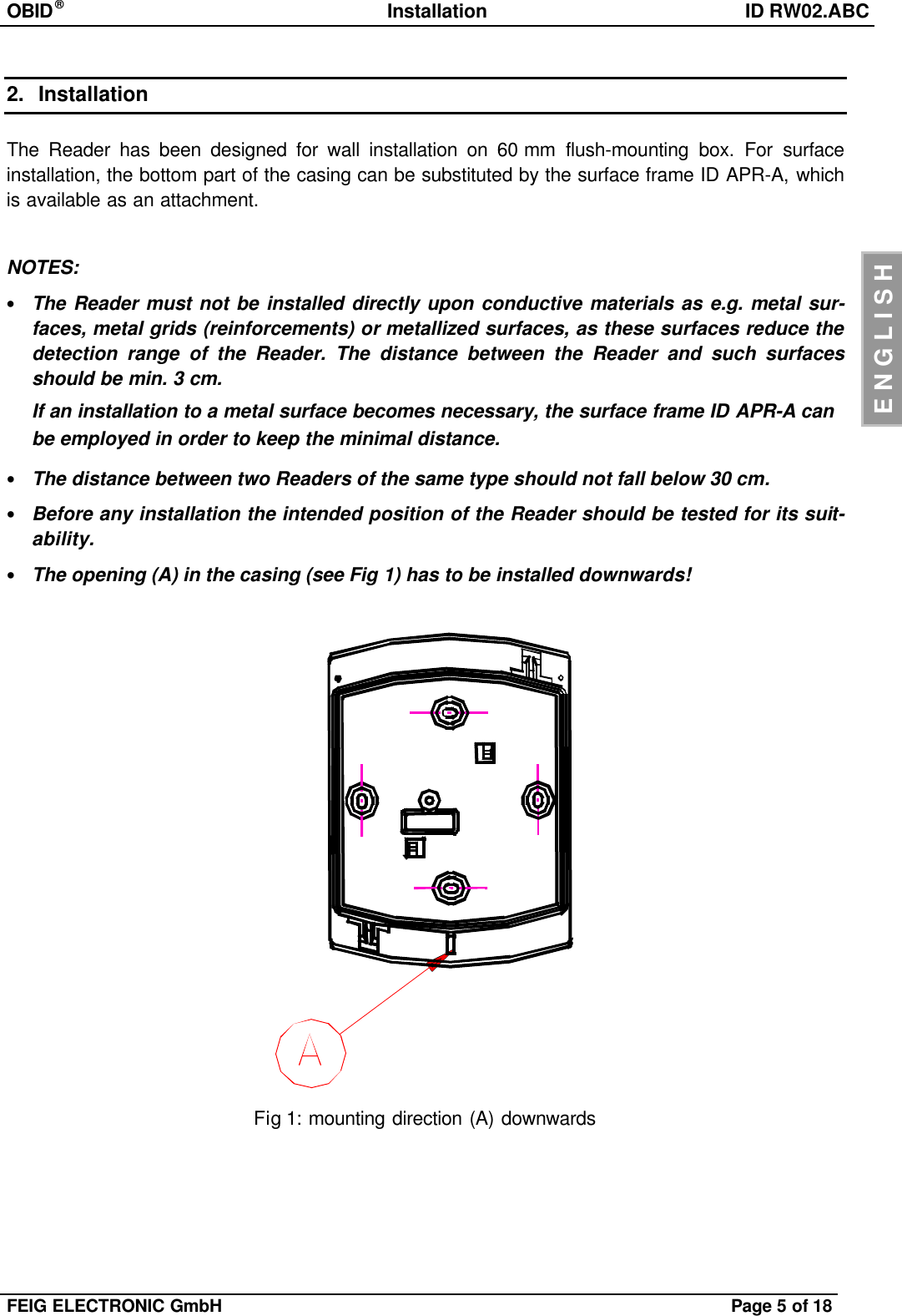
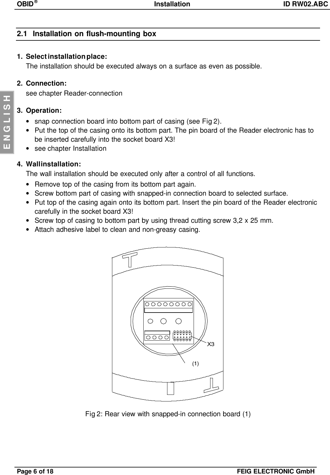
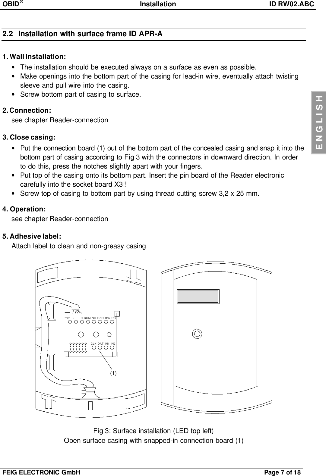
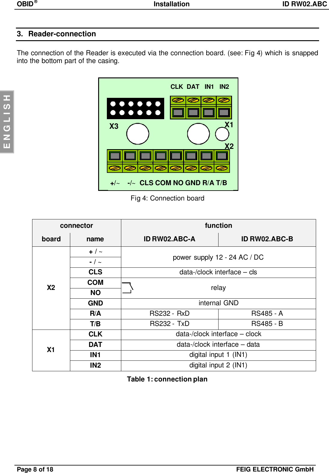
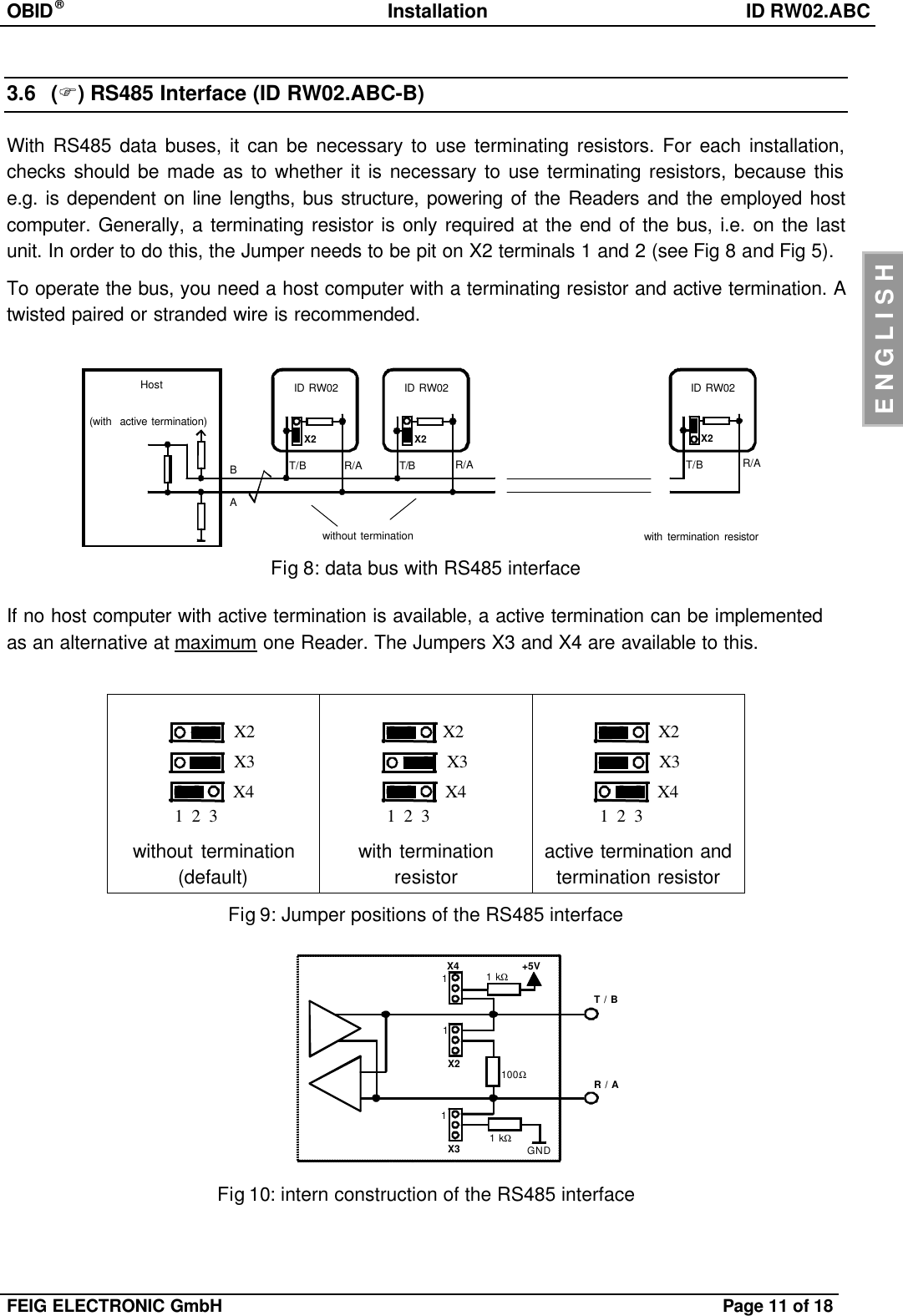
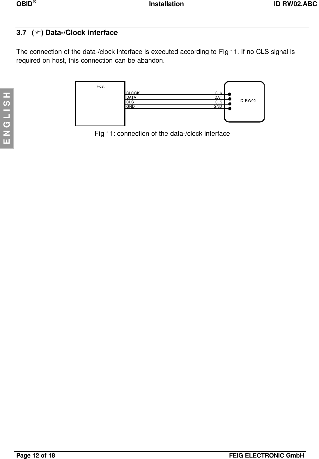
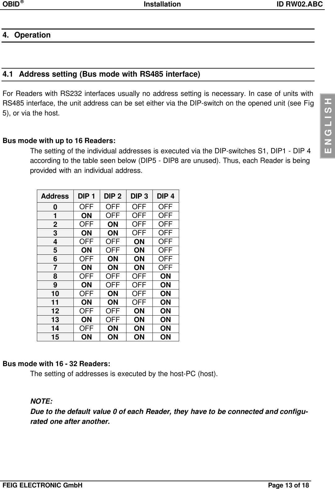
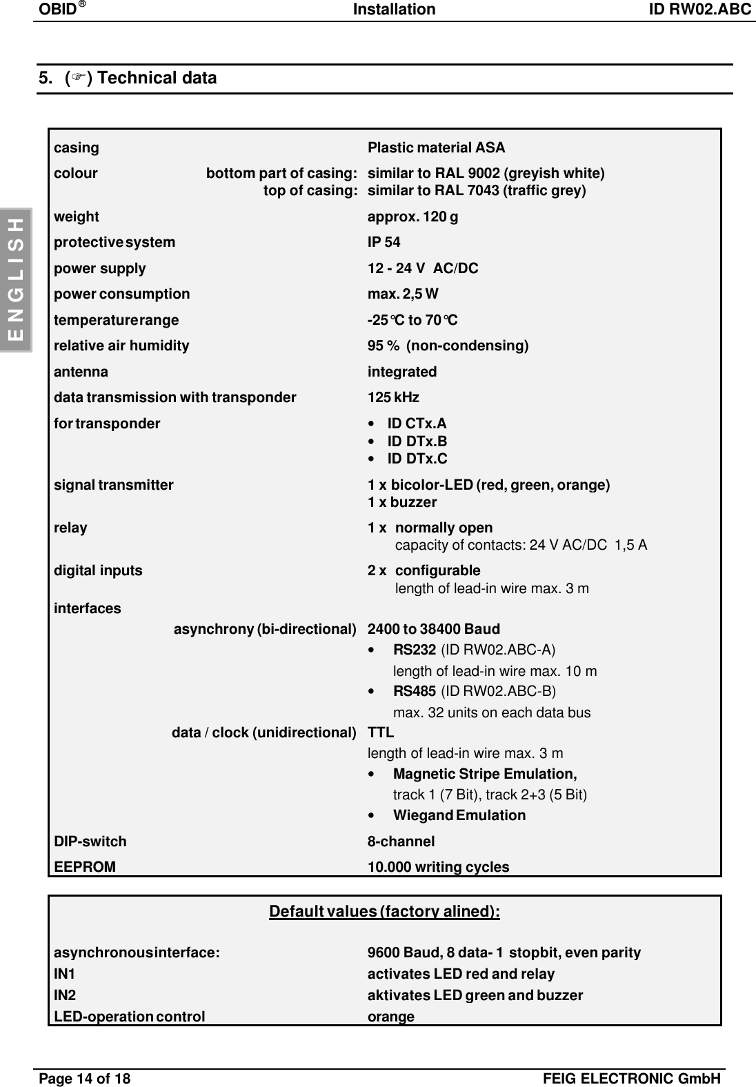
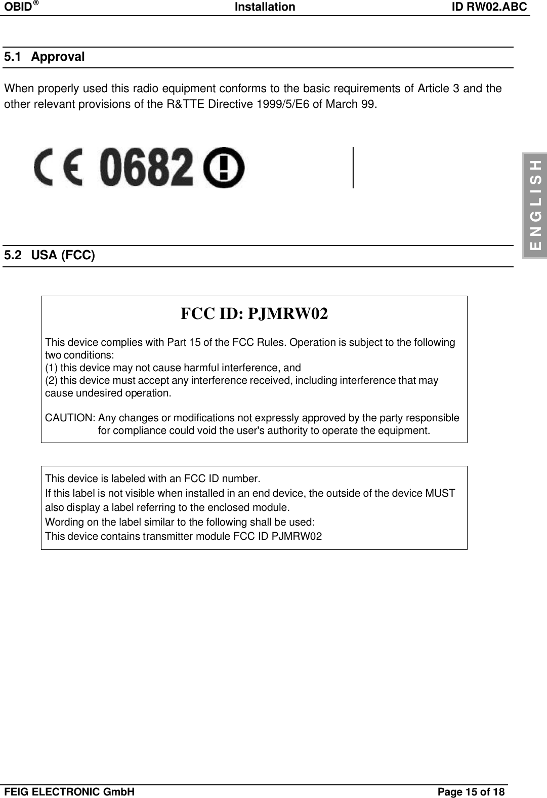
![OBID®Installation ID RW02.ABCPage 10 of 18 FEIG ELECTRONIC GmbHENGLISH3.2 Power supplyThe power supply is effected via the connectors [+ / ~] and [- / ~]. The device may be suppliedeither with 12 - 24 V AC or DC. In case of DC supply, the polarity may be chosen freely.NOTE:The lead-in wire should not be laid directly parallel to other power supply- and low voltagewires.3.3 RelayThe device is equipped with an relay (normally open contact). The connection is executed via theconnectors [NO] and [COM].3.4 Digital inputs (IN1 / IN2)The digital inputs [IN1] and [IN2] can only be connected to internal GND (terminal [GND]) accord-ing to Fig 6.Any connection to external voltage might damage the unit!Fig 6: connection of the digital inputs3.5 RS232 Interface (ID RW02.ABC-A)Readers with RS232 interface have to be connected to the host according to Fig 7.Fig 7: connection of the RS232-interfaceHostR/AT/BGND ID RW02RxDTxDGNDIN1IN2GND](https://usermanual.wiki/Feig-Electronic/RW02/User-Guide-380150-Page-10.png)