Feig Electronic RW02 Inductive Reader User Manual RW02 Manual
Feig Electronic GmbH Inductive Reader RW02 Manual
Users Manual
OBID®Installation ID RW02.ABC
FEIG ELECTRONIC GmbH Page 1of 18
ENGLISH
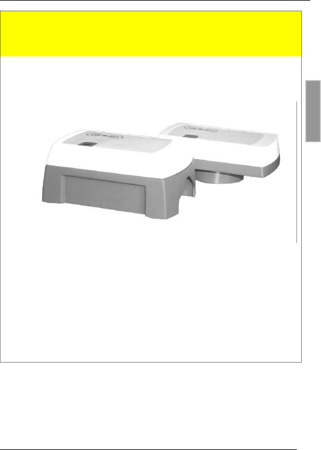
ID RW02.ABC-A (RS232 Interface)
ID RW02.ABC-B (RS485 Interface)
(english)

OBID®Installation ID RW02.ABC
Page 2of 18 FEIG ELECTRONIC GmbH
ENGLISH
Note
Copyright 1999 - 2002 by
FEIG ELECTRONIC GmbH
Lange Strasse 4
D-35781 Weilburg-Waldhausen
Tel.: +49 6471 3109-0
http://www.feig.de
With the edition of this document, all previous editions become void. Indications made in this manual may be
changed without previous notice.
Copying of this document, and giving it to others and the use or communication of the contents thereof are
forbidden without express authority. Offenders are liable to the payment of damages. All rights are reserved
in the event of the grant of a patent or the registration of a utility model or design.
Composition of the information in this document has been done to the best of our knowledge. FEIG ELEC-
TRONIC GmbH does not guarantee the correctness and completeness of the details given in this manual
and may not be held liable for damages ensuing from incorrect or incomplete information. Since, despite all
our efforts, errors may not be completely avoided, we are always grateful for your useful advises.
The instructions given in this manual are based on advantageous boundary conditions. FEIG ELECTRONIC
GmbH does not give any guarantee promise for perfect function in cross environments.
FEIG ELECTRONIC GmbH assumes no responsibility for the use of any information contained in this
document and makes no representation that they free of patent infringement. FEIG ELECTRONIC GmbH
does not convey any license under its patent rights nor the rights of others.
OBID®is registered trademark of FEIG ELECTRONIC GmbH.
General information's regarding this document
The sign "F" indicates extensions or changes of this manual compared with the former issue.

OBID®Installation ID RW02.ABC
FEIG ELECTRONIC GmbH Page 3of 18
ENGLISH
Content
1. Safety instructions 4
2. Installation 5
2.1 Installation on flush-mounting box ...........................................................................6
2.2 Installation with surface frame ID APR-A..................................................................7
3. Reader-connection 8
3.1 (F) Jumper and Switches ..........................................................................................9
3.2 Power supply.............................................................................................................10
3.3 Relay..........................................................................................................................10
3.4 Digital inputs (IN1 / IN2)............................................................................................10
3.5 RS232 Interface (ID RW02.ABC-A) ...........................................................................10
3.6 (F) RS485 Interface (ID RW02.ABC-B) ....................................................................11
3.7 (F) Data-/Clock interface..........................................................................................12
4. Operation 13
4.1 Address setting (Bus mode with RS485 interface).................................................13
5. (F) Technical data 14
5.1 Approval ....................................................................................................................15
5.2 USA (FCC)..................................................................................................................15
5.3 Dimensions for concealed installation ....................................................................16
5.4 Dimensions for surface installation with ID APR-A................................................17
6. System delivery contents: 18
6.1 Optional Accessories ...............................................................................................18

OBID®Installation ID RW02.ABC
Page 4of 18 FEIG ELECTRONIC GmbH
ENGLISH
1. Safety instructions
•The device has to be used only for the purpose designed by the manufacturer.
•The operation manual has to be stored available at any time and has to be handed over
to each user.
•Unauthorized changes and the use of spare parts and additional devices which have not
been sold or recommended by the manufacturer may cause fire, electric shocks or
injuries. Such measures will lead to exclusion of any liability by the manufacturer.
•The liability-prescriptions of the manufacturer in the issue valid at the time of purchase
are valid for the device. The manufacturer is not legally responsible for incorrect,
unsuitable manual or automatical setting of parameters for a device or the incorrect
application of a device.
•Repairs can only be executed by the manufacturer.
•Installation-, operation- and maintenance procedures should only be carried out by
qualified personnel.
•Before opening the device, the power supply must always be interrupted. Make sure
that the device is without voltage by measuring. CAUTION! The fading of an operation
control (LED) is no indicator for an interrupted power supply or the device being
without voltage!
•Works at the device and its installation have to be executed according to the national
legal requirements and local prescriptions.
•When working on devices the valid safety regulations must be observed.
OBID®Installation ID RW02.ABC
FEIG ELECTRONIC GmbH Page 5of 18
ENGLISH
2. Installation
The Reader has been designed for wall installation on 60 mm flush-mounting box. For surface
installation, the bottom part of the casing can be substituted by the surface frame ID APR-A, which
is available as an attachment.
NOTES:
•The Reader must not be installed directly upon conductive materials as e.g. metal sur-
faces, metal grids (reinforcements) or metallized surfaces, as these surfaces reduce the
detection range of the Reader. The distance between the Reader and such surfaces
should be min. 3 cm.
If an installation to a metal surface becomes necessary, the surface frame ID APR-A can
be employed in order to keep the minimal distance.
•The distance between two Readers of the same type should not fall below 30 cm.
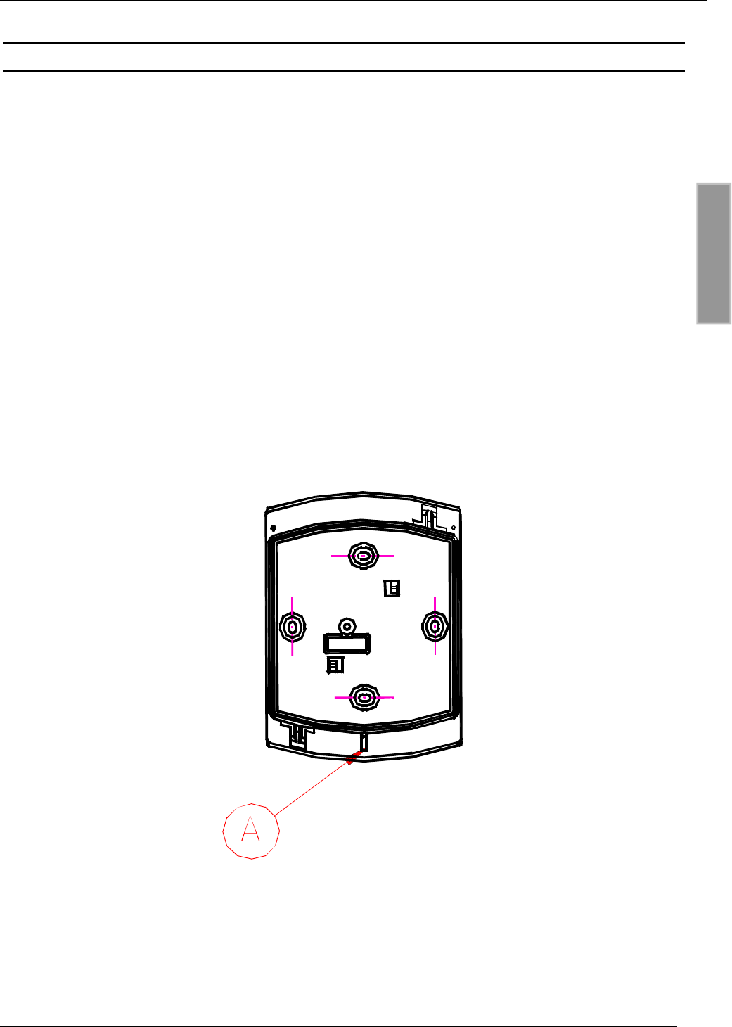
•Before any installation the intended position of the Reader should be tested for its suit-
ability.
•The opening (A) in the casing (see Fig 1) has to be installed downwards!
Fig 1: mounting direction (A) downwards
OBID®Installation ID RW02.ABC
Page 6of 18 FEIG ELECTRONIC GmbH
ENGLISH
2.1 Installation on flush-mounting box
1. Select installation place:
The installation should be executed always on a surface as even as possible.
2. Connection:
see chapter Reader-connection
3. Operation:
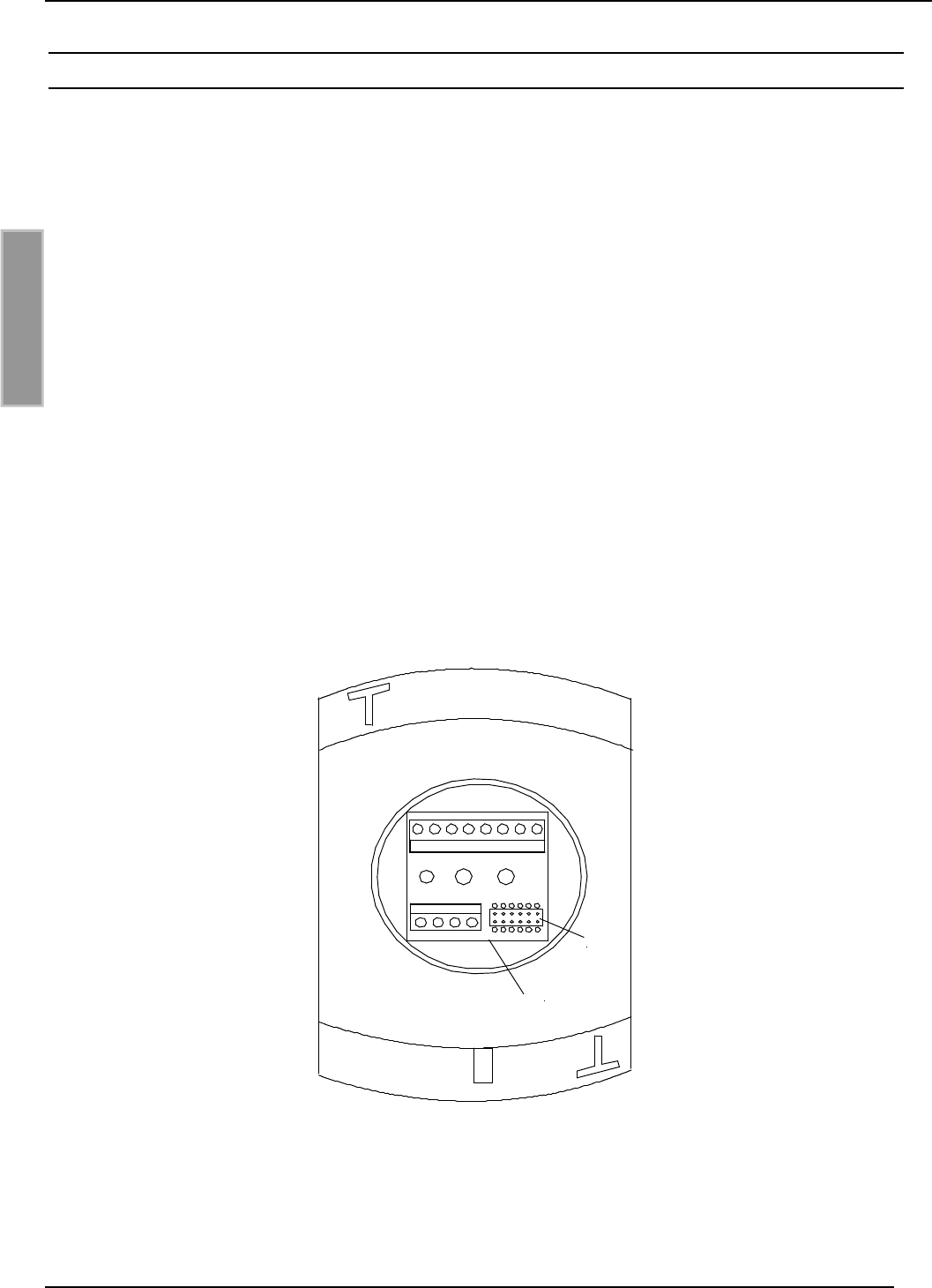
•snap connection board into bottom part of casing (see Fig 2).
•Put the top of the casing onto its bottom part. The pin board of the Reader electronic has to
be inserted carefully into the socket board X3!
•see chapter Installation
4. Wall installation:
The wall installation should be executed only after a control of all functions.
•Remove top of the casing from its bottom part again.
•Screw bottom part of casing with snapped-in connection board to selected surface.
•Put top of the casing again onto its bottom part. Insert the pin board of the Reader electronic
carefully in the socket board X3!
•Screw top of casing to bottom part by using thread cutting screw 3,2 x 25 mm.
•Attach adhesive label to clean and non-greasy casing.
(1)
X3
Fig 2: Rear view with snapped-in connection board (1)
OBID®Installation ID RW02.ABC
FEIG ELECTRONIC GmbH Page 7of 18
ENGLISH
2.2 Installation with surface frame ID APR-A
1. Wall installation:
•The installation should be executed always on a surface as even as possible.
•Make openings into the bottom part of the casing for lead-in wire, eventually attach twisting
sleeve and pull wire into the casing.
•Screw bottom part of casing to surface.
2. Connection:
see chapter Reader-connection
3. Close casing:
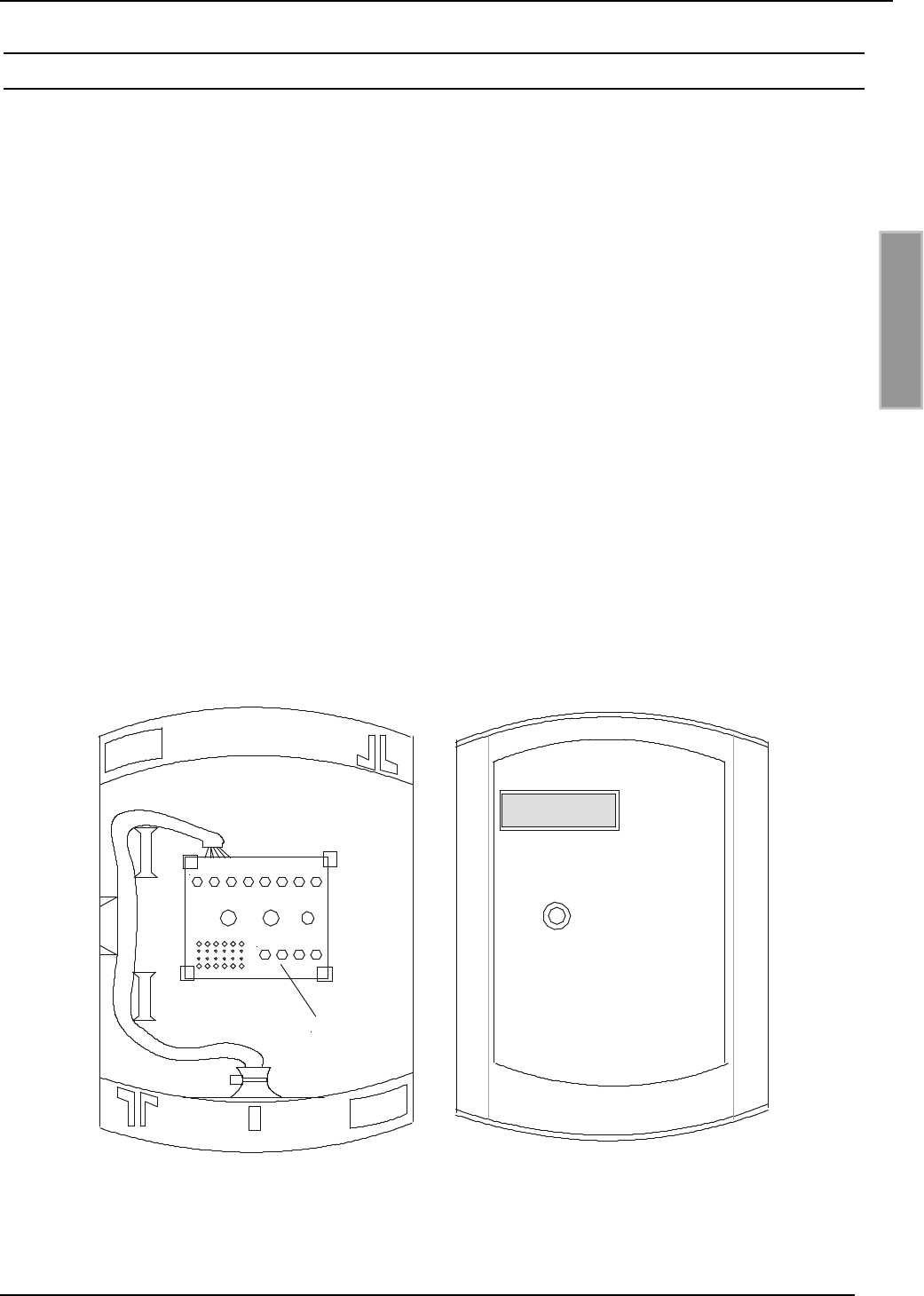
•Put the connection board (1) out of the bottom part of the concealed casing and snap it into the
bottom part of casing according to Fig 3with the connectors in downward direction. In order
to do this, press the notches slightly apart with your fingers.
•Put top of the casing onto its bottom part. Insert the pin board of the Reader electronic
carefully into the socket board X3!!
•Screw top of casing to bottom part by using thread cutting screw 3,2 x 25 mm.
4. Operation:
see chapter Reader-connection
5. Adhesive label:
Attach label to clean and non-greasy casing
+/~ -/~ R COM NO GND R/A T/B
CLK DAT IN1 IN2
(1)
Fig 3: Surface installation (LED top left)
Open surface casing with snapped-in connection board (1)
OBID®Installation ID RW02.ABC
Page 8of 18 FEIG ELECTRONIC GmbH
ENGLISH
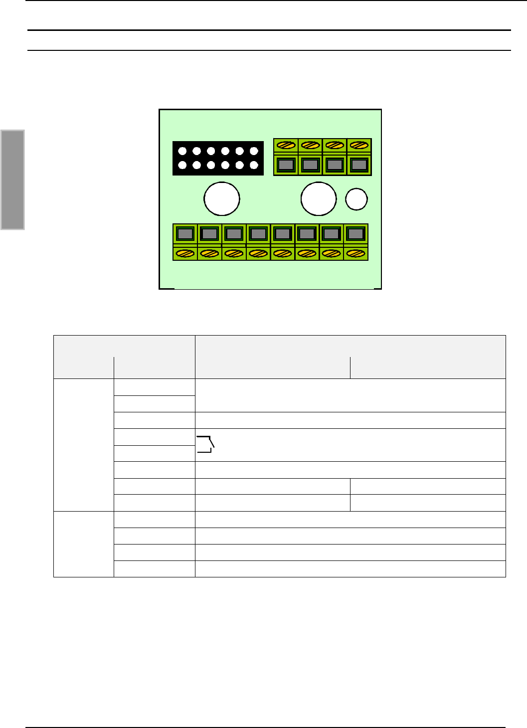
3. Reader-connection
The connection of the Reader is executed via the connection board. (see: Fig 4) which is snapped
into the bottom part of the casing.
Fig 4: Connection board
connector function
board name ID RW02.ABC-A ID RW02.ABC-B
+ / ~
- / ~power supply 12 - 24 AC / DC
CLS data-/clock interface – cls
COM
NO relay
GND internal GND
R/A RS232 - RxD RS485 - A
X2
T/B RS232 - TxD RS485 - B
CLK data-/clock interface – clock
DAT data-/clock interface – data
IN1 digital input 1 (IN1)
X1
IN2 digital input 2 (IN1)
Table 1: connection plan
CLK DAT IN1 IN2
+/~-/~CLS COM NO GND R/A T/B
X1
X2
X3
OBID®Installation ID RW02.ABC
FEIG ELECTRONIC GmbH Page 9of 18
ENGLISH
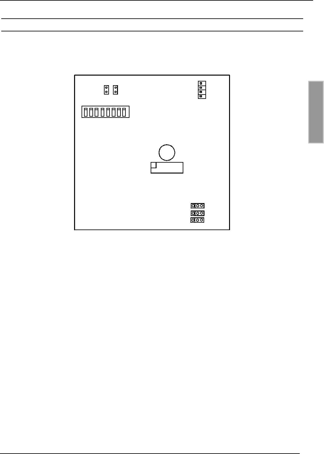
3.1 (F) Jumper and Switches
Fig 5 shows the position of the jumpers and switches on the printed circuit board of the ID
RW02.ABC. The jumpers and switches are only accessible at opened device.
1 2 3 4 5 6 7 8 ON
OFF
1 2 3
X2
X3
X4
J1 J2
S1
X1
X7
1
Fig 5: Jumper and switsches
S1:
DIP-switch to configure the Reader address.
X1:
Terminal for sticking up the connection board.
X2 / X3 / X4:
Jumper for termination resistors of the RS485 interface (only ID RW02.ABC-B).
X7:
Interface for firmware update.
J1 / J2:
Jumper for firmware update.
OBID®Installation ID RW02.ABC
Page 10 of 18 FEIG ELECTRONIC GmbH
ENGLISH
3.2 Power supply
The power supply is effected via the connectors [+ / ~] and [- / ~]. The device may be supplied
either with 12 - 24 V AC or DC. In case of DC supply, the polarity may be chosen freely.
NOTE:
The lead-in wire should not be laid directly parallel to other power supply- and low voltage
wires.
3.3 Relay
The device is equipped with an relay (normally open contact). The connection is executed via the
connectors [NO] and [COM].
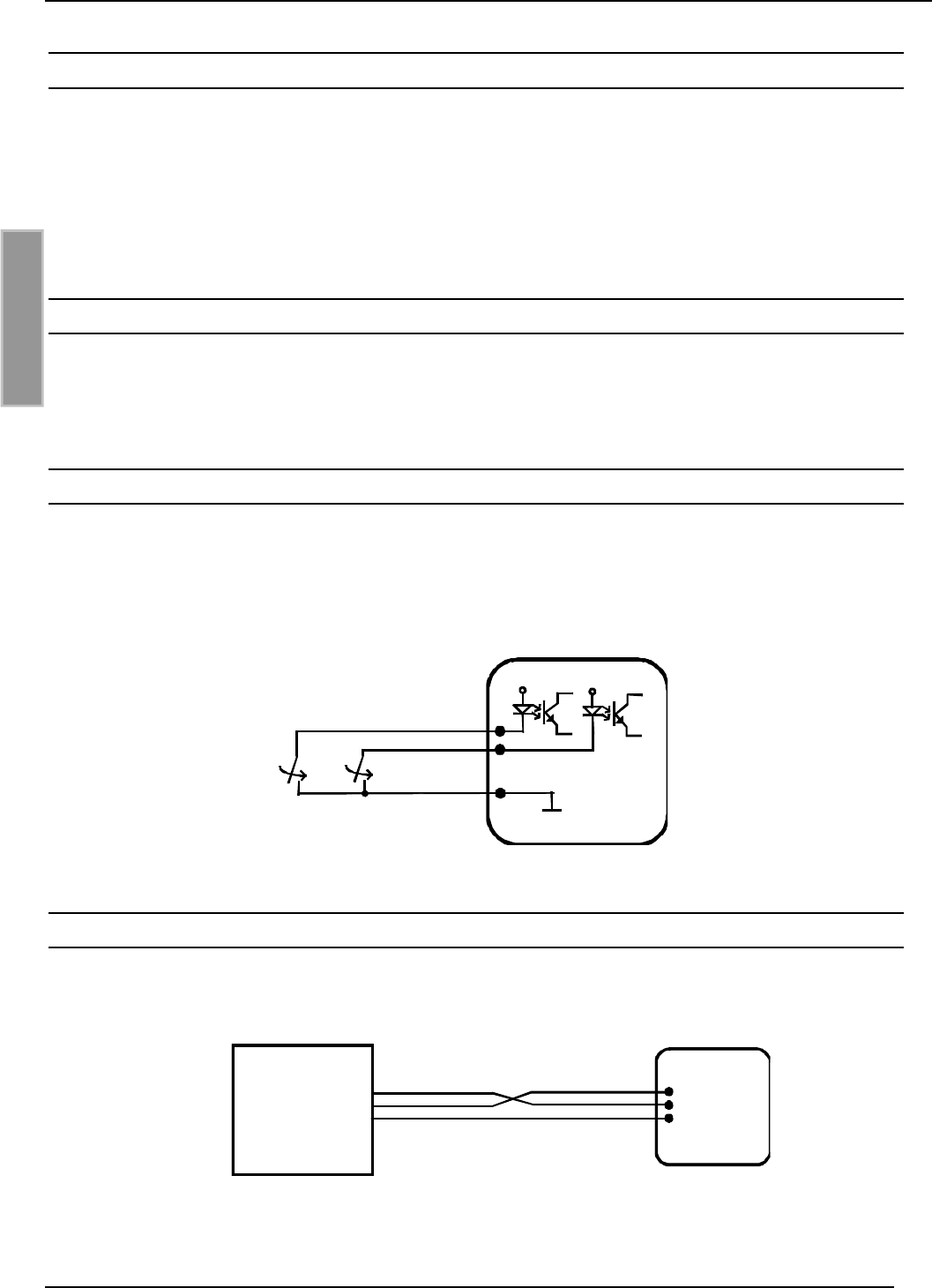
3.4 Digital inputs (IN1 / IN2)
The digital inputs [IN1] and [IN2] can only be connected to internal GND (terminal [GND]) accord-
ing to Fig 6.
Any connection to external voltage might damage the unit!
Fig 6: connection of the digital inputs
3.5 RS232 Interface (ID RW02.ABC-A)
Readers with RS232 interface have to be connected to the host according to Fig 7.
Fig 7: connection of the RS232-interface
Host
R/A
T/B
GND ID RW02
RxD
TxD
GND
IN1
IN2
GND
OBID®Installation ID RW02.ABC
FEIG ELECTRONIC GmbH Page 11 of 18
ENGLISH
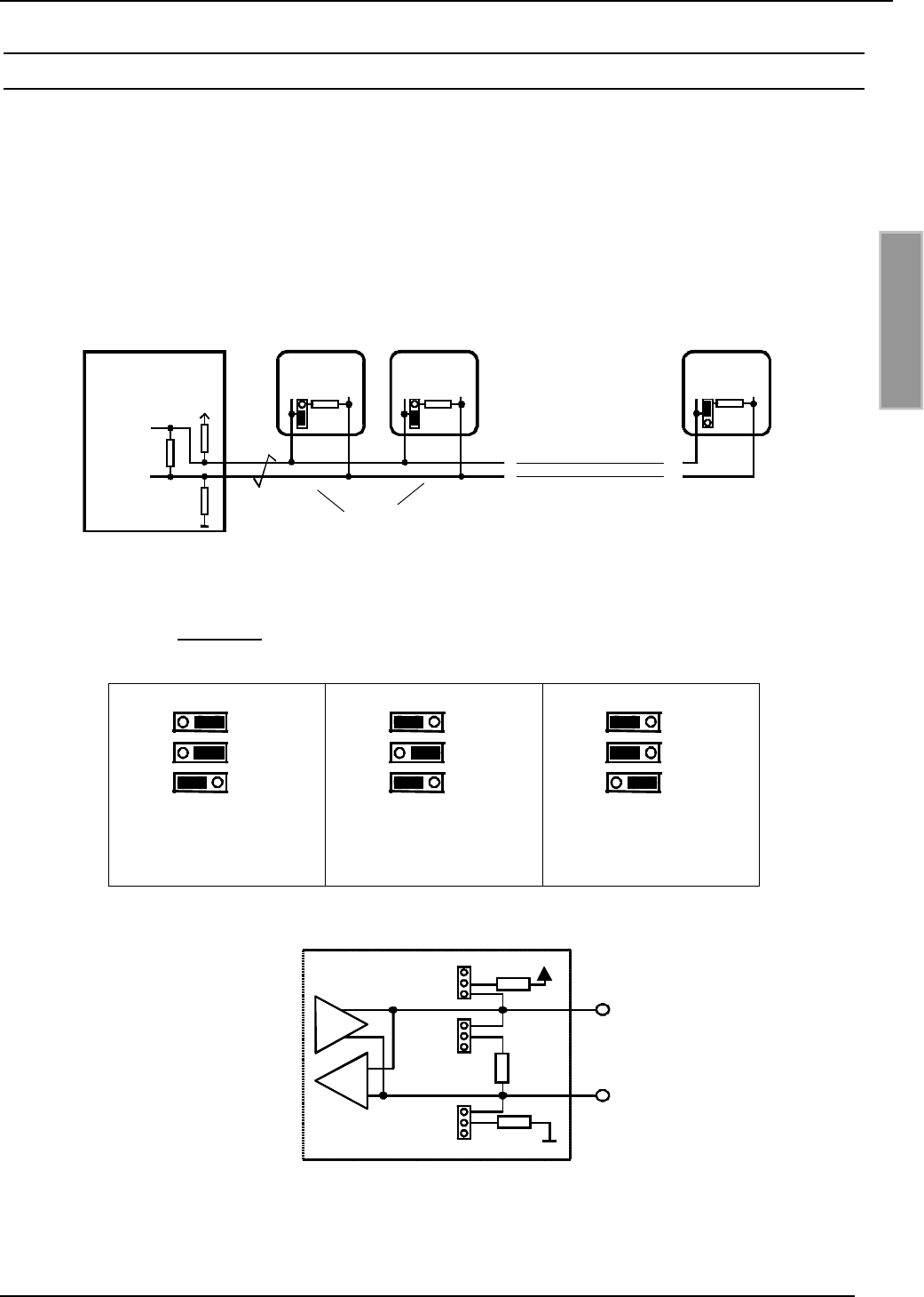
3.6 (F)RS485 Interface (ID RW02.ABC-B)
With RS485 data buses, it can be necessary to use terminating resistors. For each installation,
checks should be made as to whether it is necessary to use terminating resistors, because this
e.g. is dependent on line lengths, bus structure, powering of the Readers and the employed host
computer. Generally, a terminating resistor is only required at the end of the bus, i.e. on the last
unit. In order to do this, the Jumper needs to be pit on X2 terminals 1 and 2 (see Fig 8 and Fig 5).
To operate the bus, you need a host computer with a terminating resistor and active termination. A
twisted paired or stranded wire is recommended.
Host
without termination
R/A
T/B
ID RW02
(with active termination)
with termination resistor
A
B
X2
ID RW02
X2
ID RW02
X2
T/B T/BR/A R/A
Fig 8: data bus with RS485 interface
If no host computer with active termination is available, a active termination can be implemented
as an alternative at maximum one Reader. The Jumpers X3 and X4 are available to this.
1 2 3
X2
X3
X4
1 2 3
X2
X3
X4
1 2 3
X2
X3
X4
without termination
(default)
with termination
resistor
active termination and
termination resistor
Fig 9: Jumper positions of the RS485 interface
Fig 10: intern construction of the RS485 interface
X2
X3
X4 +5V
GND
1
T / B
R / A
1
1
1 kΩ
1 kΩ
100Ω

OBID®Installation ID RW02.ABC
Page 12 of 18 FEIG ELECTRONIC GmbH
ENGLISH
3.7 (F)Data-/Clock interface
The connection of the data-/clock interface is executed according to Fig 11. If no CLS signal is
required on host, this connection can be abandon.
Fig 11: connection of the data-/clock interface
Host
ID RW02
CLOCK
DATA
CLS
GND
CLK
DAT
CLS
GND

OBID®Installation ID RW02.ABC
FEIG ELECTRONIC GmbH Page 13 of 18
ENGLISH
4. Operation
4.1 Address setting (Bus mode with RS485 interface)
For Readers with RS232 interfaces usually no address setting is necessary. In case of units with
RS485 interface, the unit address can be set either via the DIP-switch on the opened unit (see Fig
5), or via the host.
Bus mode with up to 16 Readers:
The setting of the individual addresses is executed via the DIP-switches S1, DIP1 - DIP 4
according to the table seen below (DIP5 - DIP8 are unused). Thus, each Reader is being
provided with an individual address.
Address DIP 1 DIP 2 DIP 3 DIP 4
0OFF OFF OFF OFF
1ON OFF OFF OFF
2OFF ON OFF OFF
3ON ON OFF OFF
4OFF OFF ON OFF
5ON OFF ON OFF
6OFF ON ON OFF
7ON ON ON OFF
8OFF OFF OFF ON
9ON OFF OFF ON
10 OFF ON OFF ON
11 ON ON OFF ON
12 OFF OFF ON ON
13 ON OFF ON ON
14 OFF ON ON ON
15 ON ON ON ON
Bus mode with 16 - 32 Readers:
The setting of addresses is executed by the host-PC (host).
NOTE:
Due to the default value 0 of each Reader, they have to be connected and configu-
rated one after another.

OBID®Installation ID RW02.ABC
Page 14 of 18 FEIG ELECTRONIC GmbH
ENGLISH
5. (F)Technical data
casing Plastic material ASA
colour bottom part of casing:
top of casing: similar to RAL 9002 (greyish white)
similar to RAL 7043 (traffic grey)
weight approx. 120 g
protective system IP 54
power supply 12 - 24 V AC/DC
power consumption max. 2,5 W
temperature range -25°C to 70°C
relative air humidity 95 % (non-condensing)
antenna integrated
data transmission with transponder 125 kHz
for transponder •ID CTx.A
•ID DTx.B
•ID DTx.C
signal transmitter 1 x bicolor-LED (red, green, orange)
1 x buzzer
relay 1 x normally open
capacity of contacts: 24 V AC/DC 1,5 A
digital inputs 2 x configurable
length of lead-in wire max. 3 m
interfaces
asynchrony (bi-directional) 2400 to 38400 Baud
•RS232 (ID RW02.ABC-A)
length of lead-in wire max. 10 m
•RS485 (ID RW02.ABC-B)
max. 32 units on each data bus
data / clock (unidirectional) TTL
length of lead-in wire max. 3 m
•Magnetic Stripe Emulation,
track 1 (7 Bit), track 2+3 (5 Bit)
•Wiegand Emulation
DIP-switch 8-channel
EEPROM 10.000 writing cycles
Default values (factory alined):
asynchronous interface: 9600 Baud, 8 data- 1 stopbit, even parity
IN1 activates LED red and relay
IN2 aktivates LED green and buzzer
LED-operation control orange
OBID®Installation ID RW02.ABC
FEIG ELECTRONIC GmbH Page 15 of 18
ENGLISH
5.1 Approval
When properly used this radio equipment conforms to the basic requirements of Article 3 and the
other relevant provisions of the R&TTE Directive 1999/5/E6 of March 99.
5.2 USA (FCC)
FCC ID: PJMRW02
This device complies with Part 15 of the FCC Rules. Operation is subject to the following
two conditions:
(1) this device may not cause harmful interference, and
(2) this device must accept any interference received, including interference that may
cause undesired operation.
CAUTION: Any changes or modifications not expressly approved by the party responsible
for compliance could void the user's authority to operate the equipment.
This device is labeled with an FCC ID number.
If this label is not visible when installed in an end device, the outside of the device MUST
also display a label referring to the enclosed module.
Wording on the label similar to the following shall be used:
This device contains transmitter module FCC ID PJMRW02
OBID®Installation ID RW02.ABC
Page 16 of 18 FEIG ELECTRONIC GmbH
ENGLISH
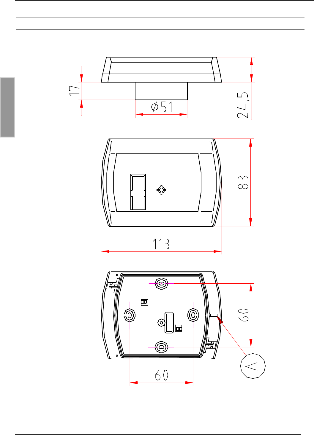
5.3 Dimensions for concealed installation
Fig 12:Dimensions of concealed casing
(A) = below
OBID®Installation ID RW02.ABC
FEIG ELECTRONIC GmbH Page 17 of 18
ENGLISH
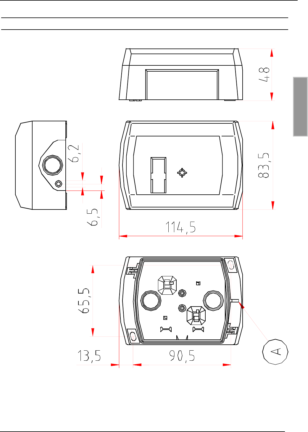
5.4 Dimensions for surface installation with ID APR-A
Fig 13: Dimensions for installation with surface frame ID APR-A
(A) = below

OBID®Installation ID RW02.ABC
Page 18 of 18 FEIG ELECTRONIC GmbH
ENGLISH
6. System delivery contents:
1 x bottom part of casing (concealed casing)
1 x top of casing with Reader electronic
1 x connection board
1 x adhesive label
1 x thread cutting screw 3,2 x 25 mm (for connecting parts of casing)
2 x thread cutting screws 3,2 x 15 mm (for wall installation)
1 x Installation instructions
6.1 Optional Accessories
bottom part of casing for surface installation
ID APR-A Order-No.: 1144.001.00
adhesive front label
ID AKL.02 Order-No.: 1424.000.00