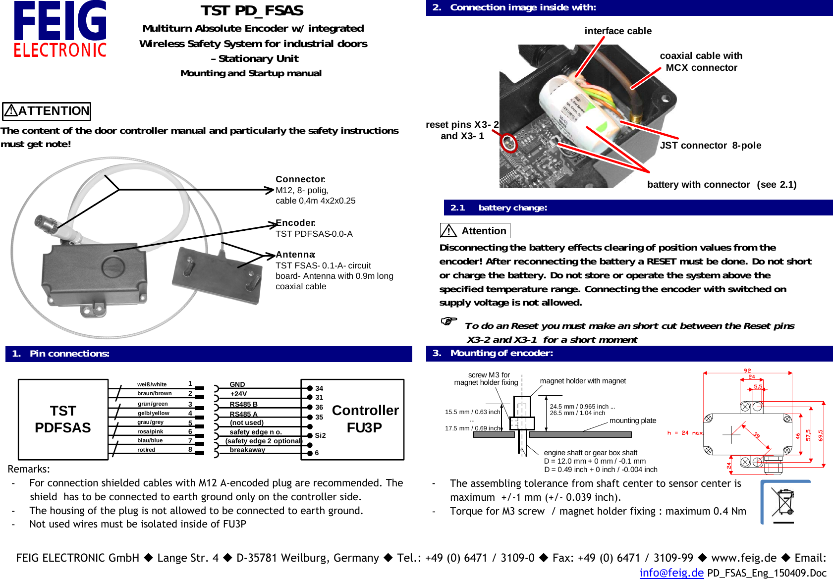
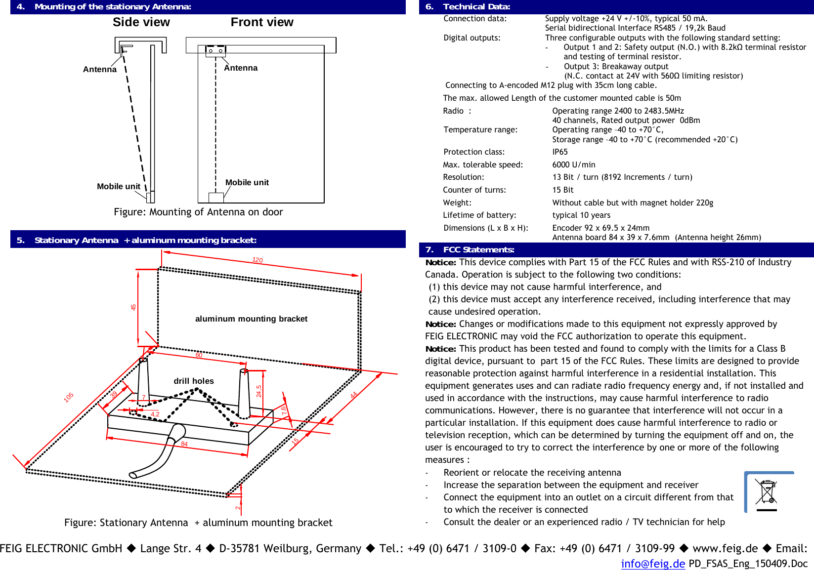
Feig Electronic TSTPDFSAS Wireless Safety System for industrial doors - Stationary Unit User Manual PD FSAS Eng 150409

Feig Electronic GmbH Wireless Safety System for industrial doors - Stationary Unit PD FSAS Eng 150409

User Manual

FEIG ELECTRONIC GmbH  Lange Str. 4  D-35781 Weilburg, Germany  Tel.: +49 (0) 6471 / 3109-0  Fax: +49 (0) 6471 / 3109-99  www.feig.de  Email:info@feig.de PD_FSAS_Eng_150409.DocTST PD_FSASMultiturn Absolute Encoder w/ integratedWireless Safety System for industrial doors – Stationary UnitMounting and Startup manual!ATTENTIONThe content of the door controller manual and particularly the safety instructionsmust get note!Connector:M12, 8- polig, cable 0,4m 4x2x0.25Encoder:TST PDFSAS-0.0-AAntenna: TST FSAS- 0.1-A- circuit board- Antenna with 0.9m long coaxial cable1. Pin connections:TST PDFSAS ControllerFU3Pbraun/brownweiß/whitegrün/greengelb/yellowgrau/greyrosa/pinkblau/bluerot/red12345678GND +24VRS485 BRS485 Asafety edge n o.breakaway34313635Si26(not used)(safety edge 2 optional)Remarks:-  For connection shielded cables with M12 A-encoded plug are recommended. Theshield  has to be connected to earth ground only on the controller side.-  The housing of the plug is not allowed to be connected to earth ground.-  Not used wires must be isolated inside of FU3P2. Connection image inside with:reset pins X3- 2and X3- 1coaxial cable with MCX connectorJST connector  8-polebattery with connector  (see 2.1)interface cable2.1     battery change:AttentionDisconnecting the battery effects clearing of position values from theencoder! After reconnecting the battery a RESET must be done. Do not shortor charge the battery. Do not store or operate the system above thespecified temperature range. Connecting the encoder with switched onsupply voltage is not allowed.)  To do an Reset you must make an short cut between the Reset pins         X3-2 and X3-1  for a short moment3. Mounting of encoder:magnet holder with magnetengine shaft or gear box shaftmounting platescrew M3 formagnet holder fixing15.5 mm / 0.63 inch17.5 mm / 0.69 inch...24.5 mm / 0.965 inch ...26.5 mm / 1.04 inchD = 0.49 inch + 0 inch / -0.004 inchD = 12.0 mm + 0 mm / -0.1 mm- The assembling tolerance from shaft center to sensor center ismaximum  +/-1 mm (+/- 0.039 inch).-  Torque for M3 screw  / magnet holder fixing : maximum 0.4 Nm
FEIG ELECTRONIC GmbH  Lange Str. 4  D-35781 Weilburg, Germany  Tel.: +49 (0) 6471 / 3109-0  Fax: +49 (0) 6471 / 3109-99  www.feig.de  Email:info@feig.de PD_FSAS_Eng_150409.Doc4. Mounting of the stationary Antenna:AntennaMobile unitSide view Front viewAntennaMobile unitFigure: Mounting of Antenna on door5. Stationary Antenna  + aluminum mounting bracket:45105120607847,61524,5394,2442drill holesaluminum mounting bracketFigure: Stationary Antenna  + aluminum mounting bracket6. Technical Data:Connection data: Supply voltage +24 V +/-10%, typical 50 mA.Serial bidirectional Interface RS485 / 19,2k BaudDigital outputs: Three configurable outputs with the following standard setting:- Output 1 and 2: Safety output (N.O.) with 8.2kΩ terminal resistorand testing of terminal resistor.- Output 3: Breakaway output(N.C. contact at 24V with 560Ω limiting resistor) Connecting to A-encoded M12 plug with 35cm long cable.The max. allowed Length of the customer mounted cable is 50mRadio  : Operating range 2400 to 2483.5MHz40 channels, Rated output power  0dBmTemperature range:  Operating range –40 to +70°C,Storage range –40 to +70°C (recommended +20°C)Protection class:  IP65Max. tolerable speed: 6000 U/minResolution: 13 Bit / turn (8192 Increments / turn)Counter of turns: 15 BitWeight:  Without cable but with magnet holder 220gLifetime of battery: typical 10 yearsDimensions (L x B x H): Encoder 92 x 69.5 x 24mmAntenna board 84 x 39 x 7.6mm  (Antenna height 26mm)7. FCC Statements:Notice: This device complies with Part 15 of the FCC Rules and with RSS-210 of IndustryCanada. Operation is subject to the following two conditions:(1) this device may not cause harmful interference, and(2) this device must accept any interference received, including interference that maycause undesired operation.Notice: Changes or modifications made to this equipment not expressly approved byFEIG ELECTRONIC may void the FCC authorization to operate this equipment.Notice: This product has been tested and found to comply with the limits for a Class Bdigital device, pursuant to  part 15 of the FCC Rules. These limits are designed to providereasonable protection against harmful interference in a residential installation. Thisequipment generates uses and can radiate radio frequency energy and, if not installed andused in accordance with the instructions, may cause harmful interference to radiocommunications. However, there is no guarantee that interference will not occur in aparticular installation. If this equipment does cause harmful interference to radio ortelevision reception, which can be determined by turning the equipment off and on, theuser is encouraged to try to correct the interference by one or more of the followingmeasures :- Reorient or relocate the receiving antenna- Increase the separation between the equipment and receiver- Connect the equipment into an outlet on a circuit different from thatto which the receiver is connected- Consult the dealer or an experienced radio / TV technician for help

Navigation menu