Feig Electronic TSTPDFSAS Wireless Safety System for industrial doors - Stationary Unit User Manual PD FSAS Eng 150409
Feig Electronic GmbH Wireless Safety System for industrial doors - Stationary Unit PD FSAS Eng 150409
User Manual
FEIG ELECTRONIC GmbH Lange Str. 4 D-35781 Weilburg, Germany Tel.: +49 (0) 6471 / 3109-0 Fax: +49 (0) 6471 / 3109-99 www.feig.de Email:
info@feig.de PD_FSAS_Eng_150409.Doc
TST PD_FSAS
Multiturn Absolute Encoder w/ integrated
Wireless Safety System for industrial doors
– Stationary Unit
Mounting and Startup manual
!
ATTENTION
The content of the door controller manual and particularly the safety instructions
must get note!
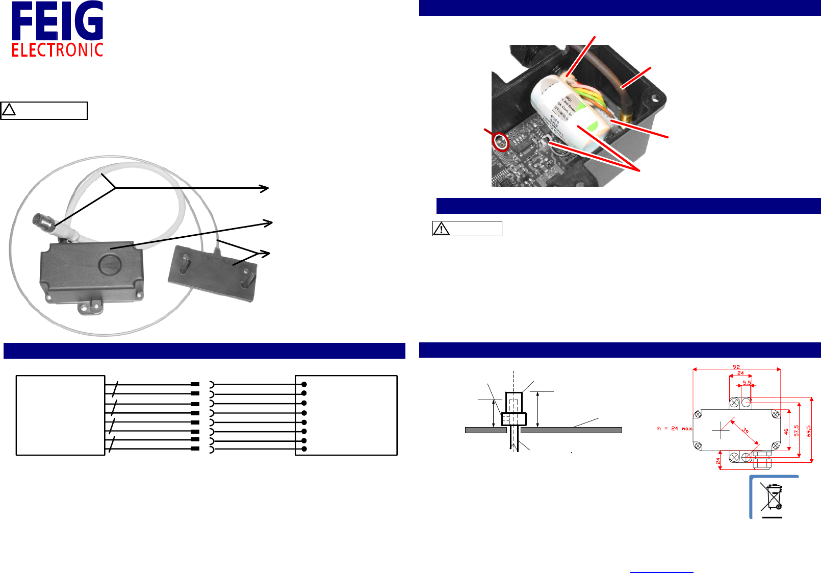
Connector:
M12, 8- polig,
cable 0,4m 4x2x0.25
Encoder:
TST PDFSAS-0.0-A
Antenna:
TST FSAS- 0.1-A- circuit
board- Antenna with 0.9m long
coaxial cable
1. Pin connections:
TST
PDFSAS Controller
FU3P
braun/brown
weiß/white
grün/green
gelb/yellow
grau/grey
rosa/pink
blau/blue
rot/red
1
2
3
4
5
6
7
8
GND
+24V
RS485 B
RS485 A
safety edge n o.
breakaway
34
31
36
35
Si2
6
(not used)
(safety edge 2 optional)
Remarks:
- For connection shielded cables with M12 A-encoded plug are recommended. The
shield has to be connected to earth ground only on the controller side.
- The housing of the plug is not allowed to be connected to earth ground.
- Not used wires must be isolated inside of FU3P
2. Connection image inside with:
reset pins X3- 2
and X3- 1
coaxial cable with
MCX connector
JST connector 8-pole
battery with connector (see 2.1)
interface cable
2.1 battery change:
Attention
Disconnecting the battery effects clearing of position values from the
encoder! After reconnecting the battery a RESET must be done. Do not short
or charge the battery. Do not store or operate the system above the
specified temperature range. Connecting the encoder with switched on
supply voltage is not allowed.
) To do an Reset you must make an short cut between the Reset pins
X3-2 and X3-1 for a short moment
3. Mounting of encoder:
magnet holder with magnet
engine shaft or gear box shaft
mounting plate
screw
M
3 fo
r
magnet holder fixing
15.5 mm / 0.63 inch
17.5 mm / 0.69 inch
...
24.5 mm / 0.965 inch ...
26.5 mm / 1.04 inch
D = 0.49 inch + 0 inch / -0.004 inch
D = 12.0 mm + 0 mm / -0.1 mm
- The assembling tolerance from shaft center to sensor center is
maximum +/-1 mm (+/- 0.039 inch).
- Torque for M3 screw / magnet holder fixing : maximum 0.4 Nm
FEIG ELECTRONIC GmbH Lange Str. 4 D-35781 Weilburg, Germany Tel.: +49 (0) 6471 / 3109-0 Fax: +49 (0) 6471 / 3109-99 www.feig.de Email:
info@feig.de PD_FSAS_Eng_150409.Doc
4. Mounting of the stationary Antenna:
Antenna
Mobile unit
Side view Front view
Antenna
Mobile unit
Figure: Mounting of Antenna on door
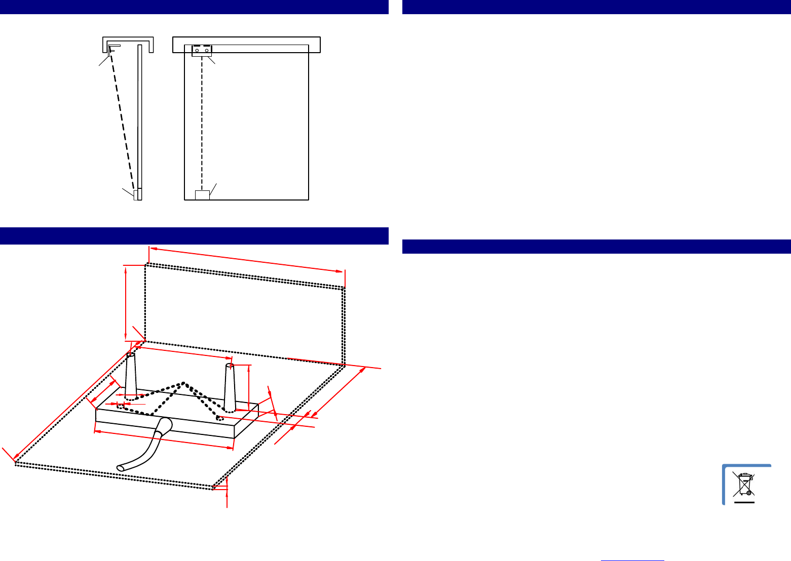
5. Stationary Antenna + aluminum mounting bracket:
45
105
120
60
7
84
7,6
15
24,5
39
4,2
44
2
drill holes
aluminum mounting bracket
Figure: Stationary Antenna + aluminum mounting bracket
6. Technical Data:
Connection data: Supply voltage +24 V +/-10%, typical 50 mA.
Serial bidirectional Interface RS485 / 19,2k Baud
Digital outputs: Three configurable outputs with the following standard setting:
- Output 1 and 2: Safety output (N.O.) with 8.2kΩ terminal resistor
and testing of terminal resistor.
- Output 3: Breakaway output
(N.C. contact at 24V with 560Ω limiting resistor)
Connecting to A-encoded M12 plug with 35cm long cable.
The max. allowed Length of the customer mounted cable is 50m
Radio : Operating range 2400 to 2483.5MHz
40 channels, Rated output power 0dBm
Temperature range: Operating range –40 to +70°C,
Storage range –40 to +70°C (recommended +20°C)
Protection class: IP65
Max. tolerable speed: 6000 U/min
Resolution: 13 Bit / turn (8192 Increments / turn)
Counter of turns: 15 Bit
Weight: Without cable but with magnet holder 220g
Lifetime of battery: typical 10 years
Dimensions (L x B x H): Encoder 92 x 69.5 x 24mm
Antenna board 84 x 39 x 7.6mm (Antenna height 26mm)
7. FCC Statements:
Notice: This device complies with Part 15 of the FCC Rules and with RSS-210 of Industry
Canada. Operation is subject to the following two conditions:
(1) this device may not cause harmful interference, and
(2) this device must accept any interference received, including interference that may
cause undesired operation.
Notice: Changes or modifications made to this equipment not expressly approved by
FEIG ELECTRONIC may void the FCC authorization to operate this equipment.
Notice: This product has been tested and found to comply with the limits for a Class B
digital device, pursuant to part 15 of the FCC Rules. These limits are designed to provide
reasonable protection against harmful interference in a residential installation. This
equipment generates uses and can radiate radio frequency energy and, if not installed and
used in accordance with the instructions, may cause harmful interference to radio
communications. However, there is no guarantee that interference will not occur in a
particular installation. If this equipment does cause harmful interference to radio or
television reception, which can be determined by turning the equipment off and on, the
user is encouraged to try to correct the interference by one or more of the following
measures :
- Reorient or relocate the receiving antenna
- Increase the separation between the equipment and receiver
- Connect the equipment into an outlet on a circuit different from that
to which the receiver is connected
- Consult the dealer or an experienced radio / TV technician for help