Fibar Group FGKF601 Fibaro KeyFob User Manual Manual 2of2
Fibar Group S.A. Fibaro KeyFob Manual 2of2
UserManual.wiki
>
Fibar Group
>
FGKF601 User Manual
>
Manual 2of2
Contents
1.
Manual 1of2
2.
Manual 2of2
Manual 2of2
Navigation menu
Upload a User Manual
Namespaces
Wiki Guide
HTML
PDF
Info
Views
User Manual
Discussion / Help
Navigation
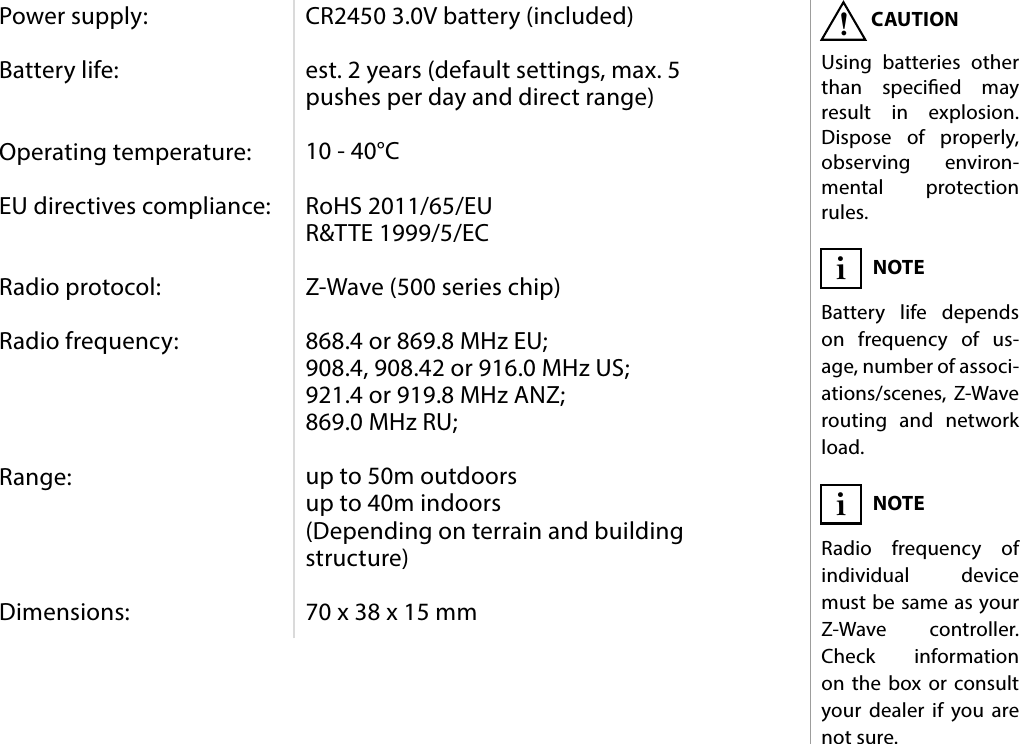
![15ADVANCED PARAMETERS#11: Advanced parameters1. Lock Mode - unlocking sequenceThis parameter allows to activate Lock Mode and set up unlocking sequence. Device will lock after time set in parameter 2 or after press-ing and holding selected button. See "Lock Mode" on page 9 for more information.Available settings: 0 - Lock Mode disabled9-28086 - unlocking sequenceDefault setting: 0Parameter size: 2 [bytes]2. Lock Mode - time to lock and locking buttonThis parameter allows to set time that must elapse from the last press of the button to lock the device and locking button. Setting locking button will deactivate associations and scenes for pressing and holding the selected button. This parameter is irrelevant if parameter 1 is set to 0 (Lock Mode disable).See "Lock Mode" on page 9 for more information.Available settings: 0 - Lock Mode disabled5-1791- calculated valueDefault setting: 60 (60s) Parameter size: 2 [bytes]3. First scene sequenceThis parameter allows to set up sequence that activates scene with ID 7. See "Sequences" on page 10 for more information.Available settings: 0 - 1st sequence disabled9-28086 - value of sequenceDefault setting: 0Parameter size: 2 [bytes]The KeyFob allows to customize its operation to user’s needs. The set-tings are available in the FIBARO interface as simple options that may be chosen by selecting the appropriate box.In order to congure the KeyFob (using the Home Center controller):1. Go to the device options by clicking the icon: 2. Select the „Advanced” tab.3. Modify values of chosen parameters.4. Save the changes.5. Press and simultaneously to wake up the device.NOTEEntering invalid value of parameter will re-sult in response with Application Rejected frame and not setting the value.i](https://usermanual.wiki/Fibar-Group/FGKF601.Manual-2of2/User-Guide-3330748-Page-4.png)
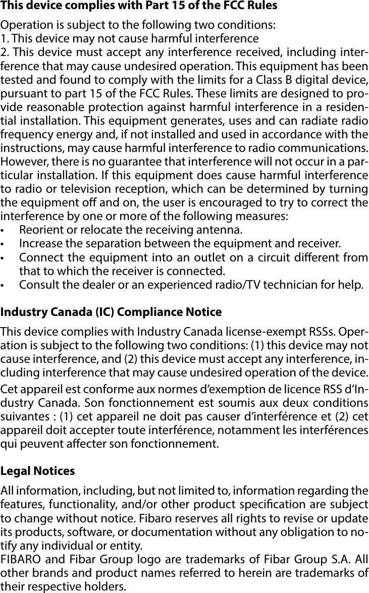
![16ADVANCED PARAMETERS4. Second scene sequenceThis parameter allows to set up sequence that activates scene with ID 8. See "Sequences" on page 10 for more information.Available settings: 0 - 1st sequence disabled9-28086 - value of sequenceDefault setting: 0Parameter size: 2 [bytes]5. Third scene sequenceThis parameter allows to set up sequence that activates scene with ID 9. See "Sequences" on page 10 for more information.Available settings: 0 - 3rd sequence disabled9-28086 - value of sequenceDefault setting: 0Parameter size: 2 [bytes]6. Fourth scene sequenceThis parameter allows to set up sequence that activates scene with ID 10. See "Sequences" on page 10 for more information.Available settings: 0 - 4th sequence disabled9-28086 - value of sequenceDefault setting: 0Parameter size: 2 [bytes]7. Fifth scene sequenceThis parameter allows to set up sequence that activates scene with ID 11. See "Sequences" on page 10 for more information.Available settings: 0 - 5th sequence disabled9-28086 - value of sequenceDefault setting: 0Parameter size: 2 [bytes]8. Sixth scene sequenceThis parameter allows to set up sequence that activates scene with ID 12. See "Sequences" on page 10 for more information.Available settings: 0 - 6th sequence disabled9-28086 - value of sequenceDefault setting: 0Parameter size: 2 [bytes]9. Sequences - timeoutThis parameter allows to set time that must elapse from the last press of the button to check if the sequence is valid.Available settings: 5-30 (0.5-3s, 0.1s step) - time to lockDefault setting: 10 (1s) Parameter size: 1 [byte]](https://usermanual.wiki/Fibar-Group/FGKF601.Manual-2of2/User-Guide-3330748-Page-5.png)
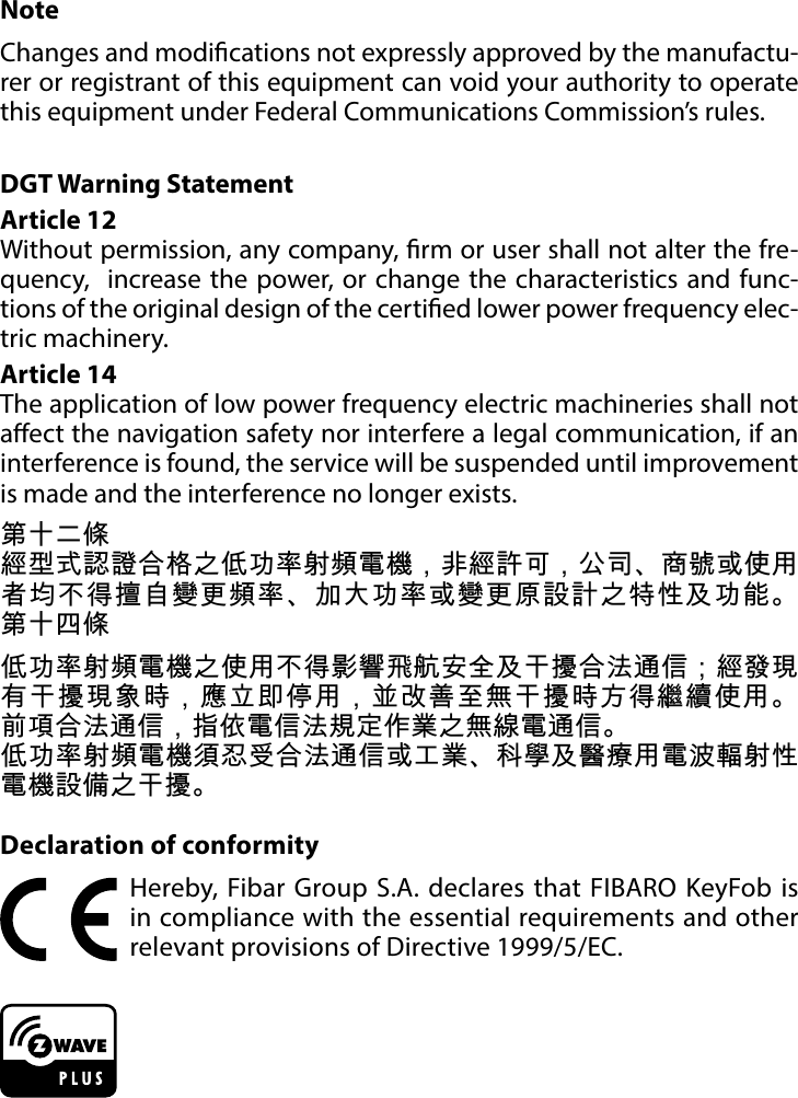
![17ADVANCED PARAMETERS10. Single button associations - operating modeThis parameter allows to choose operating mode for single button associations. Available settings: 0 - single press switches state to opposite1 - single press switches state to opposite, dou-ble press sets to maximum level2 - single press turns on, double press turns oDefault setting: 0 (switch)Parameter size: 1 [byte]11. Value sent to association group12. Value sent to association group13. Value sent to association group14. Value sent to association group15. Value sent to association group16. Value sent to association groupThis parameter allows to set value sent to devices in association group. It will result in turning multilevel devices on with set or last level. Value is irrelevant for simple on/o devices.Available settings: 1-99 or 255Default setting: 255 Parameter size: 2 [bytes]17. Paired buttons association for and This parameter allows to activate paired buttons association mode for and buttons. Paired buttons are dependent and association are sent only to groups. turns devices on and increases value, turns them o and decreases value.Available settings: 0 - paired buttons association inactive1 - paired buttons association activeDefault setting: 0 (inactive) Parameter size: 1 [byte]18. Paired buttons association for and This parameter allows to activate paired buttons association mode for and buttons. Paired buttons are dependent and association are sent only to groups. turns devices on and increases value, turns them o and decreases value.Available settings: 0 - paired buttons association inactive1 - paired buttons association activeDefault setting: 0 (inactive) Parameter size: 1 [byte]NOTESetting parameters 11-16 to appropriate value will result in:1-99 - forcing level of associated devices255 - setting associat-ed devices to the last remembered state or turning them oni](https://usermanual.wiki/Fibar-Group/FGKF601.Manual-2of2/User-Guide-3330748-Page-6.png)
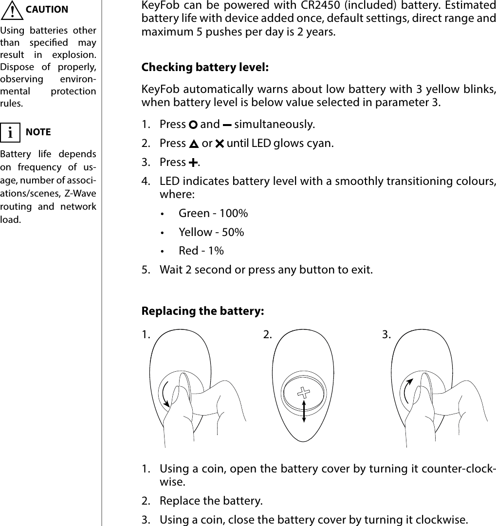
![18ADVANCED PARAMETERS19. Paired buttons association for and This parameter allows to activate paired buttons association mode for and buttons. Paired buttons are dependent and association are sent only to groups. turns devices on and increases value, turns them o and decreases value. Available settings: 0 - paired buttons association inactive1 - paired buttons association activeDefault setting: 0 (inactive) Parameter size: 1 [byte]21. Scene activation for button22. Scene activation for button23. Scene activation for button24. Scene activation for button25. Scene activation for button26. Scene activation for buttonThis parameter determines which actions result in sending assigned scene IDs and attributes to the controller.Available settings: 1 - Key Pressed 1 time2 - Key Pressed 2 times4 - Key Pressed 3 times8 - Key Held Down & ReleasedDefault setting: 9 (1x & hold) Parameter size: 1 [byte]29. Associations in Z-Wave network security modeParameter defines how commands are sent in specified association groups: as secure or non-secure. Parameter is active only in Z-Wave network security mode. It does not apply to 1st “Lifeline” association group.Available settings: 1 - 2nd group sent as secure2 - 3rd group sent as secure4 - 4th group sent as secure8 - 5th group sent as secure16 - 6th group sent as secure32 - 7th group sent as secure64 - 8th group sent as secure128 - 9th group sent as secure256 - 10th group sent as secure512 - 11th group sent as secure1024 - 12th group sent as secure2048 - 13th group sent as secureDefault setting: 4095 Parameter size: 2 [bytes]NOTEParameter 29 values may be combined, e.g. 1+2=3 means that 2nd & 3rd group are sent as secure.iNOTEParameters 21 to 26 values may be com-bined, e.g. 1+2=3 means that pressing button once or twice will result in sending assigned scene ID.i](https://usermanual.wiki/Fibar-Group/FGKF601.Manual-2of2/User-Guide-3330748-Page-7.png)