Fibar Group FGKF601 Fibaro KeyFob User Manual Manual 2of2
Fibar Group S.A. Fibaro KeyFob Manual 2of2
Contents
- 1. Manual 1of2
- 2. Manual 2of2
Manual 2of2
12
BATTERY
#9: Battery
Checking battery level:
KeyFob automatically warns about low battery with 3 yellow blinks,
when battery level is below value selected in parameter 3.
1. Press and simultaneously.
2. Press or until LED glows cyan.
3. Press .
4. LED indicates battery level with a smoothly transitioning colours,
where:
• Green - 100%
• Yellow - 50%
• Red - 1%
5. Wait 2 second or press any button to exit.
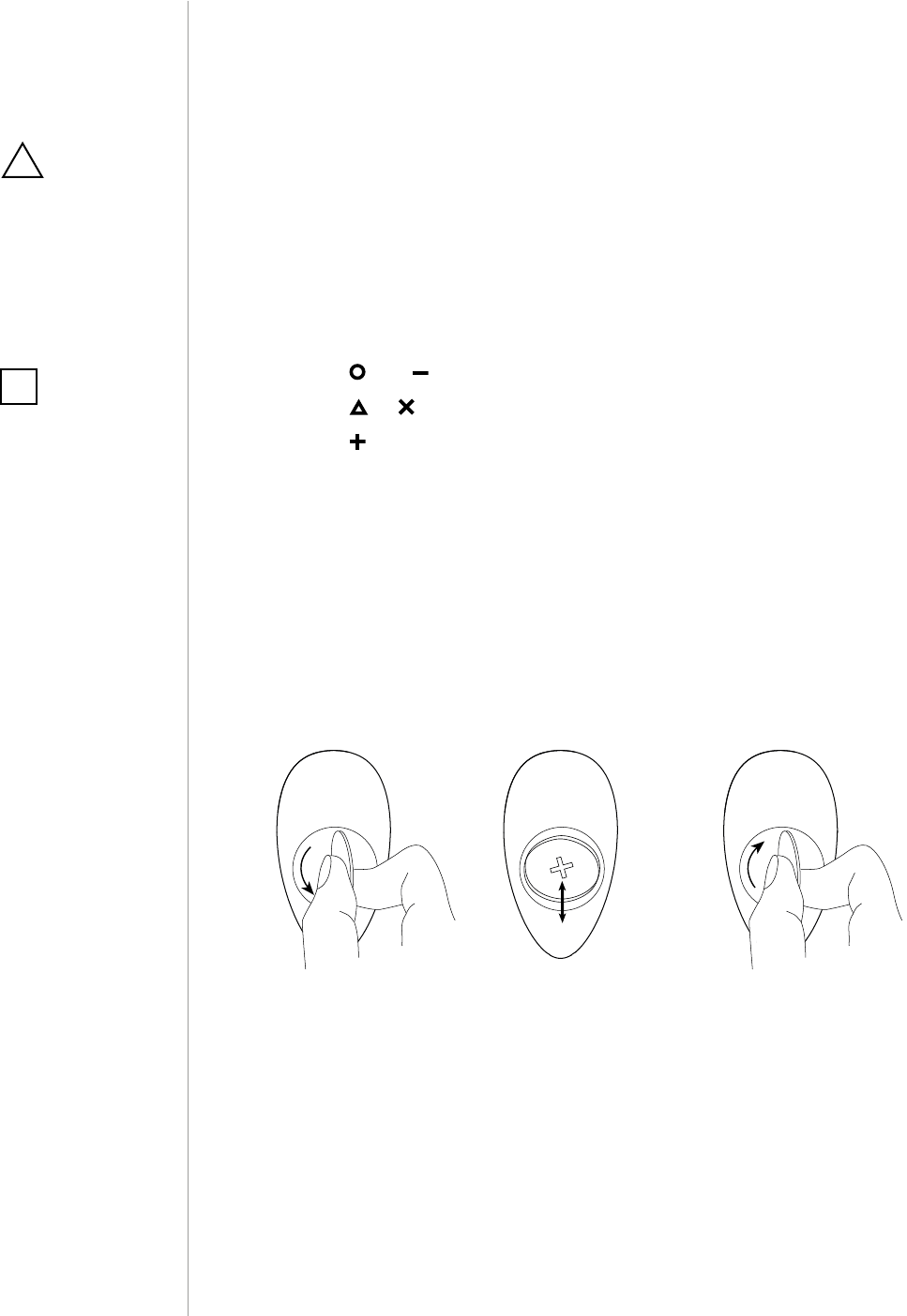
Replacing the battery:
KeyFob can be powered with CR2450 (included) battery. Estimated
battery life with device added once, default settings, direct range and
maximum 5 pushes per day is 2 years.
o
s
e
o
s
e
1.
1. Using a coin, open the battery cover by turning it counter-clock-
wise.
2. Replace the battery.
3. Using a coin, close the battery cover by turning it clockwise.
2. 3.
CAUTION
Using batteries other
than specied may
result in explosion.
Dispose of properly,
observing environ-
mental protection
rules.
!
NOTE
Battery life depends
on frequency of us-
age, number of associ-
ations/scenes, Z-Wave
routing and network
load.
i
13
ASSOCIATIONS
#10: Associations
The device provides the association of thirteen groups:
1st association group – “Lifeline” reports the device status and al-
lows for assigning single device only (main controller by default).
2nd association group – “Square - On/O” is assigned to clicking
the button and is used to turn on/o associated devices.
3rd association group – “Square - Multilevel” is assigned to click-
ing and holding the button and is used to turn on/o and change
level of associated devices.
4th association group – “Circle - On/O” is assigned to clicking the
button and is used to turn on/o associated devices.
5th association group – “Circle - Multilevel” is assigned to clicking
and holding the button and is used to turn on/o and change level
of associated devices.
6th association group – “Cross - On/O” is assigned to clicking the
button and is used to turn on/o associated devices.
7th association group – “Cross - Multilevel” is assigned to clicking
and holding the button and is used to turn on/o and change level
of associated devices.
8th association group – “Triangle - On/O” is assigned to clicking
the button and is used to turn on/o associated devices.
9th association group – “Triangle - Multilevel” is assigned to click-
ing and holding the button and is used to turn on/o and change
level of associated devices.
10th association group – “Minus - On/O” is assigned to clicking
the button and is used to turn on/o associated devices.
11th association group – “Minus - Multilevel” is assigned to clicking
and holding the button and is used to turn on/o and change level of
associated devices.
12th association group – “Plus - On/O” is assigned to clicking the
button and is used to turn on/o associated devices.
13th association group – “Plus - Multilevel” is assigned to clicking
and holding the button and is used to turn on/o and change level
of associated devices.
Association (linking devices) - direct control of other devices within
the Z-Wave system network e.g. Dimmer, Relay Switch, Roller Shutter
or scene (may be controlled only through a Z-Wave controller).
NOTE
Association ensures
direct transfer of
control commands
between devices, is
performed without
participation of the
main controller and
requires associated
device to be in the di-
rect range.
i
NOTE
States of the associa-
tion groups are aect-
ed only by buttons.
Changing state of
associated device by
other means will not
update remembered
state of association
group.
i
NOTE
2, 4, 6, 8, 10 and 12 as-
sociation groups use
BASIC CC, but device
does not repond to
GET commands.
i
14
BATTERY
To add an association (using the Home Center controller):
1. Go to the device options by clicking the icon:
2. Select the „Advanced” tab.
3. Click the “Setting Association” button.
4. Specify to which group and what devices are to be associated.
5. Save the changes.
6. Press and simultaneously to wake up the device.
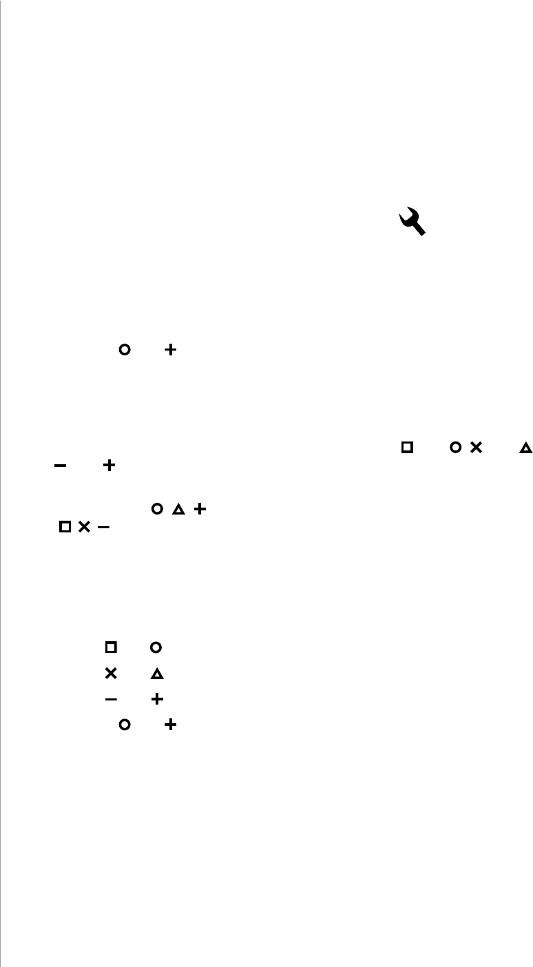
Paired buttons association
After pairing buttons, horizontal pairs of buttons
(
and
, and ,
and ) work as one button and send associations to left buttons
groups only.
Left buttons ( , , ) turn on associated devices and right buttons
(, , ) turn them o.
In multilevel association groups (3, 7, 11) left buttons increase level
while holding and right buttons decrease it.
To pair buttons:
1. Change settings of parameters:
•
and
– set parameter 6 to value 1
• and – set parameter 7 to value 1
• and – set parameter 8 to value 1
2. Press and simultaneously to wake up the device.
The KeyFob in 2nd to 13th group allows to control 5 reg-
ular or multichannel devices per an association group.
“LifeLine” group is reserved solely for the controller and hence only 1
node can be assigned.
It is not recommended to associate more than 10 devices in general,
as the response time to control commands depends on the number of
associated devices. In extreme cases, system response may be delayed.
15
ADVANCED PARAMETERS
#11: Advanced parameters
1. Lock Mode - unlocking sequence
This parameter allows to activate Lock Mode and set up unlocking
sequence. Device will lock after time set in parameter 2 or after press-
ing and holding selected button. See "Lock Mode" on page 9 for more
information.
Available settings: 0 - Lock Mode disabled
9-28086 - unlocking sequence
Default setting: 0Parameter size: 2 [bytes]
2. Lock Mode - time to lock and locking button
This parameter allows to set time that must elapse from the last press
of the button to lock the device and locking button.
Setting locking button will deactivate associations and scenes for
pressing and holding the selected button.
This parameter is irrelevant if parameter 1 is set to 0 (Lock Mode
disable).
See "Lock Mode" on page 9 for more information.
Available settings: 0 - Lock Mode disabled
5-1791- calculated value
Default setting: 60 (60s) Parameter size: 2 [bytes]
3. First scene sequence
This parameter allows to set up sequence that activates scene
with ID 7. See "Sequences" on page 10 for more information.
Available settings: 0 - 1st sequence disabled
9-28086 - value of sequence
Default setting: 0Parameter size: 2 [bytes]
The KeyFob allows to customize its operation to user’s needs. The set-
tings are available in the FIBARO interface as simple options that may
be chosen by selecting the appropriate box.
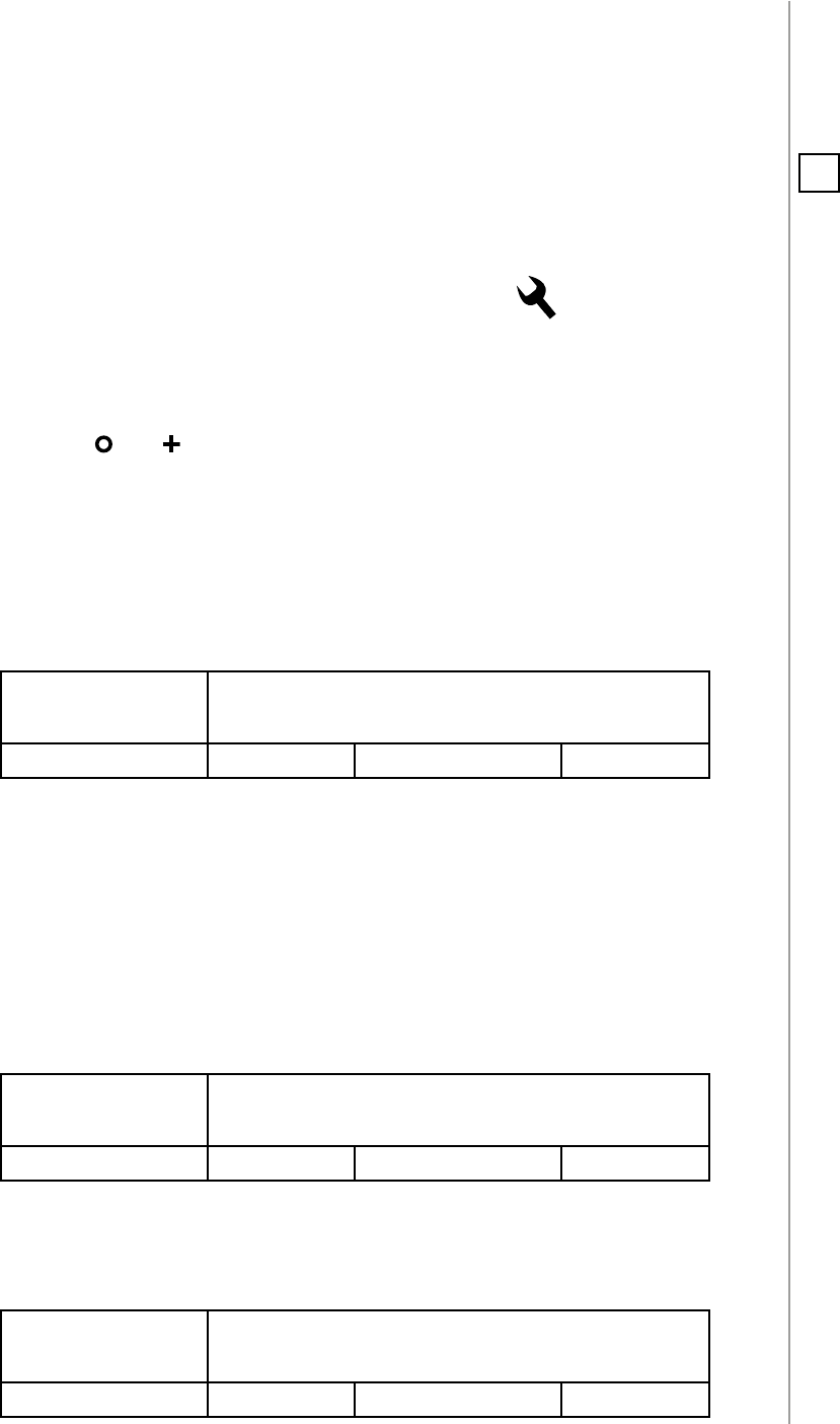
In order to congure the
KeyFob
(using the Home Center controller):
1. Go to the device options by clicking the icon:
2. Select the „Advanced” tab.
3. Modify values of chosen parameters.
4. Save the changes.
5. Press and simultaneously to wake up the device.
NOTE
Entering invalid value
of parameter will re-
sult in response with
Application Rejected
frame and not setting
the value.
i
16
ADVANCED PARAMETERS
4. Second scene sequence
This parameter allows to set up sequence that activates scene
with ID 8. See "Sequences" on page 10 for more information.
Available settings: 0 - 1st sequence disabled
9-28086 - value of sequence
Default setting: 0Parameter size: 2 [bytes]
5. Third scene sequence
This parameter allows to set up sequence that activates scene
with ID 9. See "Sequences" on page 10 for more information.
Available settings: 0 - 3rd sequence disabled
9-28086 - value of sequence
Default setting: 0Parameter size: 2 [bytes]
6. Fourth scene sequence
This parameter allows to set up sequence that activates scene
with ID 10. See "Sequences" on page 10 for more information.
Available settings: 0 - 4th sequence disabled
9-28086 - value of sequence
Default setting: 0Parameter size: 2 [bytes]
7. Fifth scene sequence
This parameter allows to set up sequence that activates scene
with ID 11. See "Sequences" on page 10 for more information.
Available settings: 0 - 5th sequence disabled
9-28086 - value of sequence
Default setting: 0Parameter size: 2 [bytes]
8. Sixth scene sequence
This parameter allows to set up sequence that activates scene
with ID 12. See "Sequences" on page 10 for more information.
Available settings: 0 - 6th sequence disabled
9-28086 - value of sequence
Default setting: 0Parameter size: 2 [bytes]
9. Sequences - timeout
This parameter allows to set time that must elapse from the last press
of the button to check if the sequence is valid.
Available settings: 5-30 (0.5-3s, 0.1s step) - time to lock
Default setting: 10 (1s) Parameter size: 1 [byte]
17
ADVANCED PARAMETERS
10. Single button associations - operating mode
This parameter allows to choose operating mode for single button
associations.
Available settings: 0 - single press switches state to opposite
1 - single press switches state to opposite, dou-
ble press sets to maximum level
2 - single press turns on, double press turns o
Default setting: 0
(switch)
Parameter size: 1 [byte]
11. Value sent to association group
12. Value sent to association group
13. Value sent to association group
14. Value sent to association group
15. Value sent to association group
16. Value sent to association group
This parameter allows to set value sent to devices in association
group. It will result in turning multilevel devices on with set or last
level. Value is irrelevant for simple on/o devices.
Available settings: 1-99 or 255
Default setting: 255 Parameter size: 2 [bytes]
17. Paired buttons association for and
This parameter allows to activate paired buttons association mode
for and buttons. Paired buttons are dependent and association
are sent only to groups. turns devices on and increases value,
turns them o and decreases value.
Available settings: 0 - paired buttons association inactive
1 - paired buttons association active
Default setting: 0 (inactive) Parameter size: 1 [byte]
18. Paired buttons association for and
This parameter allows to activate paired buttons association mode
for and buttons. Paired buttons are dependent and association
are sent only to groups. turns devices on and increases value,
turns them o and decreases value.
Available settings: 0 - paired buttons association inactive
1 - paired buttons association active
Default setting: 0 (inactive) Parameter size: 1 [byte]
NOTE
Setting parameters
11-16 to appropriate
value will result in:
1-99 - forcing level of
associated devices
255 - setting associat-
ed devices to the last
remembered state or
turning them on
i
18
ADVANCED PARAMETERS
19. Paired buttons association for and
This parameter allows to activate paired buttons association mode
for and buttons. Paired buttons are dependent and association
are sent only to groups. turns devices on and increases value,
turns them o and decreases value.
Available settings: 0 - paired buttons association inactive
1 - paired buttons association active
Default setting: 0 (inactive) Parameter size: 1 [byte]
21. Scene activation for button
22. Scene activation for button
23. Scene activation for button
24. Scene activation for button
25. Scene activation for button
26. Scene activation for button
This parameter determines which actions result in sending assigned
scene IDs and attributes to the controller.
Available settings: 1 - Key Pressed 1 time
2 - Key Pressed 2 times
4 - Key Pressed 3 times
8 - Key Held Down & Released
Default setting: 9 (1x & hold) Parameter size: 1 [byte]
29. Associations in Z-Wave network security mode
Parameter defines how commands are sent in specified association
groups: as secure or non-secure. Parameter is active only in Z-Wave
network security mode. It does not apply to 1st “Lifeline” association
group.
Available settings: 1 - 2nd group sent as secure
2 - 3rd group sent as secure
4 - 4th group sent as secure
8 - 5th group sent as secure
16 - 6th group sent as secure
32 - 7th group sent as secure
64 - 8th group sent as secure
128 - 9th group sent as secure
256 - 10th group sent as secure
512 - 11th group sent as secure
1024 - 12th group sent as secure
2048 - 13th group sent as secure
Default setting: 4095 Parameter size: 2 [bytes]
NOTE
Parameter 29 values
may be combined,
e.g. 1+2=3 means that
2nd & 3rd group are
sent as secure.
i
NOTE
Parameters 21 to 26
values may be com-
bined, e.g. 1+2=3
means that pressing
button once or twice
will result in sending
assigned scene ID.
i
19
SPECIFICATIONS
#12: Specications
Power supply:
Battery life:
Operating temperature:
EU directives compliance:
Radio protocol:
Radio frequency:
Range:
Dimensions:
CR2450 3.0V battery (included)
est. 2 years (default settings, max. 5
pushes per day and direct range)
10 - 40°C
RoHS 2011/65/EU
R&TTE 1999/5/EC
Z-Wave (500 series chip)
868.4 or 869.8 MHz EU;
908.4, 908.42 or 916.0 MHz US;
921.4 or 919.8 MHz ANZ;
869.0 MHz RU;
up to 50m outdoors
up to 40m indoors
(Depending on terrain and building
structure)
70 x 38 x 15 mm
CAUTION
Using batteries other
than specied may
result in explosion.
Dispose of properly,
observing environ-
mental protection
rules.
!
NOTE
Radio frequency of
individual device
must be same as your
Z-Wave controller.
Check information
on the box or consult
your dealer if you are
not sure.
i
NOTE
Battery life depends
on frequency of us-
age, number of associ-
ations/scenes, Z-Wave
routing and network
load.
i

20
REGULATIONS
#13: Regulations
This device complies with Part 15 of the FCC Rules
Operation is subject to the following two conditions:
1. This device may not cause harmful interference
2. This device must accept any interference received, including inter-
ference that may cause undesired operation. This equipment has been
tested and found to comply with the limits for a Class B digital device,
pursuant to part 15 of the FCC Rules. These limits are designed to pro-
vide reasonable protection against harmful interference in a residen-
tial installation. This equipment generates, uses and can radiate radio
frequency energy and, if not installed and used in accordance with the
instructions, may cause harmful interference to radio communications.
However, there is no guarantee that interference will not occur in a par-
ticular installation. If this equipment does cause harmful interference
to radio or television reception, which can be determined by turning
the equipment o and on, the user is encouraged to try to correct the
interference by one or more of the following measures:
• Reorient or relocate the receiving antenna.
• Increase the separation between the equipment and receiver.
• Connect the equipment into an outlet on a circuit dierent from
that to which the receiver is connected.
• Consult the dealer or an experienced radio/TV technician for help.
Industry Canada (IC) Compliance Notice
This device complies with Industry Canada license-exempt RSSs. Oper-
ation is subject to the following two conditions: (1) this device may not
cause interference, and (2) this device must accept any interference, in-
cluding interference that may cause undesired operation of the device.
Cet appareil est conforme aux normes d’exemption de licence RSS d’In-
dustry Canada. Son fonctionnement est soumis aux deux conditions
suivantes : (1) cet appareil ne doit pas causer d’interférence et (2) cet
appareil doit accepter toute interférence, notamment les interférences
qui peuvent aecter son fonctionnement.
Legal Notices
All information, including, but not limited to, information regarding the
features, functionality, and/or other product specication are subject
to change without notice. Fibaro reserves all rights to revise or update
its products, software, or documentation without any obligation to no-
tify any individual or entity.
FIBARO and Fibar Group logo are trademarks of Fibar Group S.A. All
other brands and product names referred to herein are trademarks of
their respective holders.

21
REGULATIONS
Note
Changes and modications not expressly approved by the manufactu-
rer or registrant of this equipment can void your authority to operate
this equipment under Federal Communications Commission’s rules.
DGT Warning Statement
Article 12
Without permission, any company, rm or user shall not alter the fre-
quency, increase the power, or change the characteristics and func-
tions of the original design of the certied lower power frequency elec-
tric machinery.
Article 14
The application of low power frequency electric machineries shall not
aect the navigation safety nor interfere a legal communication, if an
interference is found, the service will be suspended until improvement
is made and the interference no longer exists.
第十二條
經型式認證合格之低功率射頻電機,非經許可,公司、商號或使用
者均不得擅自變更頻率、加大功率或變更原設計之特性及功能。
第十四條
低功率射頻電機之使用不得影響飛航安全及干擾合法通信;經發現
有干擾現象時,應立即停用,並改善至無干擾時方得繼續使用。
前項合法通信,指依電信法規定作業之無線電通信。
低功率射頻電機須忍受合法通信或工業、科學及醫療用電波輻射性
電機設備之干擾。
Declaration of conformity
Hereby, Fibar Group S.A. declares that FIBARO KeyFob is
in compliance with the essential requirements and other
relevant provisions of Directive 1999/5/EC.