Fibar Group FGWPB121 Fibaro Wall Plug User Manual
Fibar Group S.A. Fibaro Wall Plug
UserManual.wiki
>
Fibar Group
>
FGWPB121 User Manual
>
User Manual
Contents
1.
User Manual
2.
User manual
User Manual
Navigation menu
Upload a User Manual
Namespaces
Wiki Guide
HTML
PDF
Info
Views
User Manual
Discussion / Help
Navigation
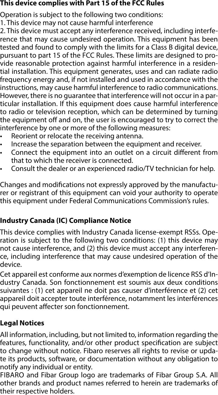
![9POWER AND ENERGY CONSUMPTION#6: Power and energy consumptionThe Wall Plug allows to monitor the active power and energy con-sumption. Data is sent to the main Z-Wave controller, e.g. Home Cen-ter. Measuring is carried out by the most advanced micro-controller tech-nology, assuring maximum accuracy and precision (+/- 1% for loads greater than 5W).Power and energy are reported according to parameters 11-15. For loads under 5W power is reported for every 0.2W change. For USB port power is not reported for loads under 0.4W.Electric active power - power that energy receiver is changing into a work or a heat. The unit of active power is Watt [W].Electric energy - energy consumed by a device through a time period. Consumers of electricity in households are billed by sup-pliers on the basis of active power used in given unit of time. Most commonly measured in kilowatt-hour [kWh]. One kilowatt-hour is equal to one kilowatt of power consumed over period of one hour, 1kWh = 1000Wh.Resetting consumption memory:Wall Plug allows to erase stored consumption data (turning it o/on or removing it from the socket will not erase consumption):1. Make sure the device is powered.2. Press and hold the button.3. Release the button when the LED frame glows green (1st menu position).4. Press the button briey.](https://usermanual.wiki/Fibar-Group/FGWPB121.User-Manual/User-Guide-3630073-Page-9.png)
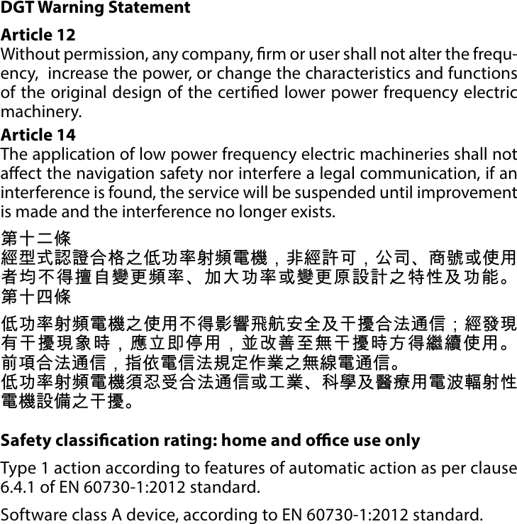
![12ZWAVE SPECIFICATIONCommand Class Version SecureZWAVEPLUS_INFO [0x5E] V2SWITCH_BINARY [0x25] V1 YESASSOCIATION [0x85] V2 YESMULTI_CHANNEL_ASSOCIATION [0x8E] V3 YESASSOCIATION_GRP_INFO [0x59] V2 YESTRANSPORT_SERVICE [0x55] V2VERSION [0x86] V2 YESMANUFACTURER_SPECIFIC [0x72] V2 YESDEVICE_RESET_LOCALLY [0x5A] V1 YESPOWERLEVEL [0x73] V1 YESSECURITY [0x98] V1SECURITY_2 [0x9F] V1SUPERVISION [0x6C] V1 YESMETER [0x32] V3 YESAPPLICATION_STATUS [0x22] V1CONFIGURATION [0x70] V1 YESCRC_16_ENCAP [0x56] V1NOTIFICATION [0x71] V8 YESPROTECTION [0x75] V1 YESFIRMWARE_UPDATE_MD [0x7A] V4MULTI_CHANNEL [0x60] V4 YESBASIC [0x20] V1 YES#9: Z-Wave specicationEndpoint 1:Generic Device Class: GENERIC_TYPE_SWITCH_BINARYSpecic Device Class: SPECIFIC_TYPE_POWER_SWITCH_BINARYDescription: represents the main B type socket, allows to turn on/o connected device and measure its active power and en-ergy consumption.Endpoint 2:Generic Device Class: GENERIC_TYPE_METER Specic Device Class: SPECIFIC_TYPE_SIMPLE_METERDescription: represents the USB port, allows to measure its active power and energy consumption.Supported Command Classes:](https://usermanual.wiki/Fibar-Group/FGWPB121.User-Manual/User-Guide-3630073-Page-12.png)
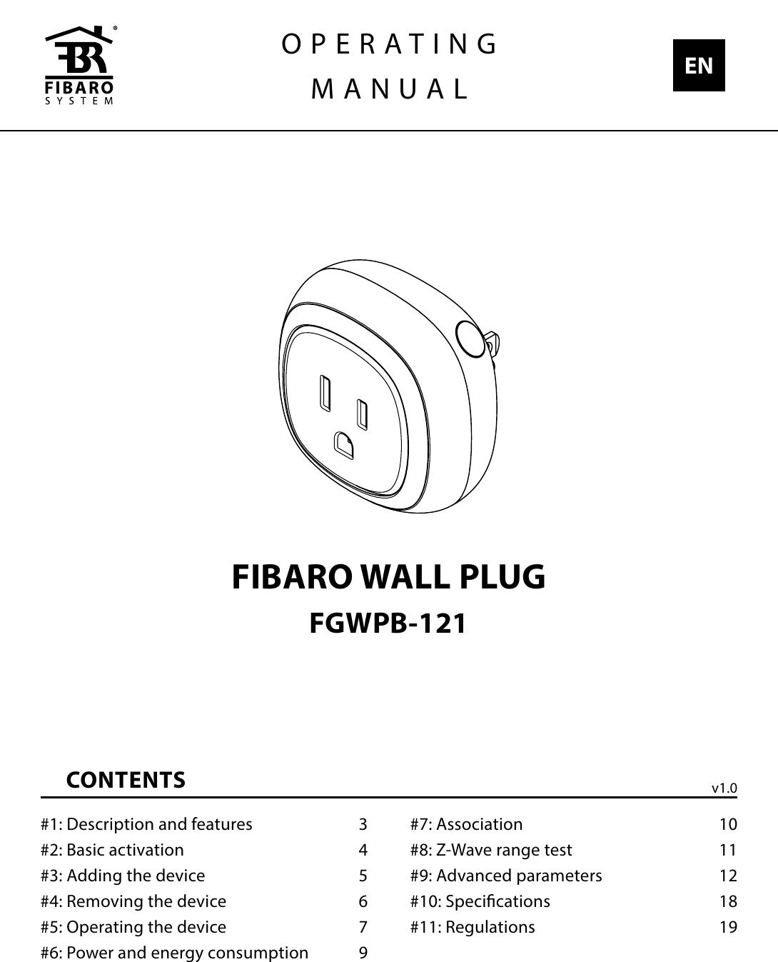
![13ZWAVE SPECIFICATIONNotication Command Class: The device uses Notication Command Class to report dierent events to the controller (“Lifeline” group).Notication Type Event Event ParametersPower Management [0x08]Over-load detected [0x08]Over-current detected [0x06]System [0x09]System Hardware Failure [0x03] Device overheat [0x01]Command Class Version SecureEndpoint 1ZWAVEPLUS_INFO [0x5E] V2SECURITY [0x98] V1SECURITY_2 [0x9F] V1ASSOCIATION [0x85] V2 YESMULTI_CHANNEL_ASSOCIATION [0x8E] V3 YESASSOCIATION_GRP_INFO [0x59] V2 YESSUPERVISION [0x6C] V1 YESSWITCH_BINARY [0x25] V1 YESMETER [0x32] V3 YESNOTIFICATION [0x71] V8 YESPROTECTION [0x75] V1 YESEndpoint 2ZWAVEPLUS_INFO [0x5E] V2SECURITY [0x98] V1SECURITY_2 [0x9F] V1ASSOCIATION [0x85] V2 YESMULTI_CHANNEL_ASSOCIATION [0x8E] V3 YESASSOCIATION_GRP_INFO [0x59] V2 YESSUPERVISION [0x6C] V1 YESMETER [0x32] V3 YESMultichannel Command Class:](https://usermanual.wiki/Fibar-Group/FGWPB121.User-Manual/User-Guide-3630073-Page-13.png)
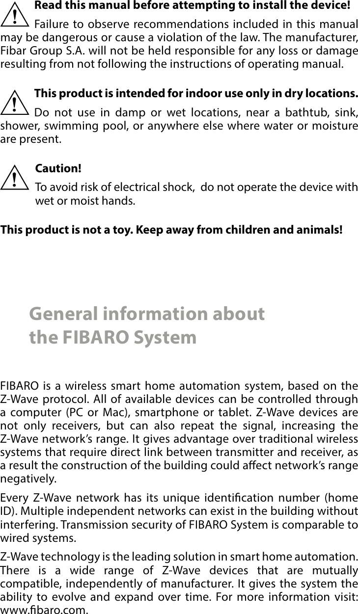
![14ADVANCED PARAMETERS#10: Advanced parametersThe Wall Plug allows to customize its operation to user’s needs. The settings are available in the FIBARO interface as simple options that may be chosen by selecting the appropriate box.In order to congure the Wall Plug (using the FIBARO Home Center controller):1. Go to the device options by clicking the icon: 2. Select the „Advanced” tab.3. Modify values of chosen parameters.4. Save the changes.GENERAL SETTINGS2. Remember device status before the power failureThis parameter determines how the Wall Plug will react in the event of power supply failure (e.g. power outage or taking out from the electrical outlet). After the power supply is back on, the Wall Plug can be restored to previous state or remain switched o. Available settings: 0 - device remains switched o1 - device restores the state from before the power failureDefault setting: 1Parameter size: 1 [byte]3. Overload safety switchThis function allows to turn o the controlled device in case of ex-ceeding the dened power. Controlled device can be turned back on via button or sending a con-trol frame. By default this function is inactive. Available settings: 0 - function inactive10-18000 (1.0-1800.0W, step 0.1W) - power thresholdDefault setting: 0Parameter size: 2 [bytes]POWER AND ENERGY MEASUREMENTThe default values of the parameters suit most types of devices. They were selected to show in real time the instantaneous power values, while not overloading the Z-Wave network in the process. In specic cases it may be necessary to modify default settings in order to op-timize Z-Wave network’s use. In extreme cases it is recommended to turn o reporting completely and congure power polling or period-NOTEEntering invalid value of parameter will re-sult in not setting the value and response with Application Re-jected or Supervision CC frame and (de-pending on the con-troller). i](https://usermanual.wiki/Fibar-Group/FGWPB121.User-Manual/User-Guide-3630073-Page-14.png)
![15ADVANCED PARAMETERSic reports in the Z-Wave controller. The Wall Plug reports the power load with specied frequency. Below conguration parameters allow to specify how frequently power load will be reported.11. Power reportingThis parameter determines the minimum percentage change in active power consumption (in relation to the previously reported) that will result in sending new power report. Available settings: 0 - power reports inactive1-100 - power change in percentDefault setting: 15 (15%) Parameter size: 1 [byte]12. Energy reporting thresholdThis parameter determines the minimum change in energy consump-tion (in relation to the previously reported) that will result in sending a new report.Available settings: 0 - energy reports inactive1-500 (0.01-5kWh, step 0.01kWh) - thresholdDefault setting: 10 (0.1kWh)Parameter size: 2 [bytes]13. Periodic power reportingThis parameter denes time period between independent reports sent when changes in power load have not been recorded or if chang-es are insignicant. By default reports are sent every hour.Available settings: 0 - periodic reports inactive5-32400 (in seconds)Default setting: 3600 (1h) Parameter size: 2 [bytes]14. Periodic energy reportingThis parameter denes time period between independent reports sent when changes in power load have not been recorded or if chang-es are insignicant. By default reports are sent every hour.Available settings: 0 - periodic reports inactive5-32400 (in seconds)Default setting: 3600 (1h) Parameter size: 2 [bytes]15. Measuring energy consumed by the Wall Plug itselfThis parameter determines whether power metering should include the amount of power consumed by the Wall Plug itself. Results are being added to the value of power consumed by controlled device.Available settings: 0 - function inactive1 - function activeDefault setting: 0Parameter size: 1 [byte]NOTEIn extreme cases, re-ports may be sent every second if rapid and signicant load power changes oc-cur. Frequent report-ing may overload the Z-Wave network so these parameter’s set-tings should reect signicant changes in power load only.iNOTEParameter 11 is not relevant for loads un-der 5W.i](https://usermanual.wiki/Fibar-Group/FGWPB121.User-Manual/User-Guide-3630073-Page-15.png)
![16ADVANCED PARAMETERS„ON/OFF” ASSOCIATION GROUPS21. UP value - „On/O (Power)” association group (3) Upper power threshold, used in parameter 23. UP value cannot be lower than a value specied in parameter 22.Available settings: 100-18000 (10.0-1800.0W, step 0.1W)Default setting: 500 (50W) Parameter size: 2 [bytes]22. DOWN value - „On/O (Power)” association group (3)Lower power threshold, used in parameter 23. DOWN value cannot be higher than a value specied in parameter 21.Available settings: 0-17900 (0.0-1790.0W, step 0.1W)Default setting: 300 (30W) Parameter size: 2 [bytes]23. Controlling „On/O (Power)” association group (3) This parameter denes the way that 3rd association group devices are controlled. Depends on the actual measured power (according to parameters 21 and 22 settings).Available settings:1 - send frame (with value set in parameter 26)only if power exceeded value of parameter 212 - send frame (with value set in parameter 27) only if power dropped below value of parame-ter 223 - send frame in both casesDefault setting: 3Parameter size: 1 [byte]24. SWITCH ON value - „On/O (Button)” association group (2)The value of BASIC SET command frame sent to the devices associat-ed in 2nd group „On/O (Button)” when turning the device ON using the button.Available settings: 0-99 or 255Default setting: 255 Parameter size: 2 [bytes]25. SWITCH OFF value - „On/O (Button)” association group (2)The value of BASIC SET command frame sent to the devices associat-ed in 2nd group „On/O (Button)” when turning the device OFF using the button.Available settings: 0-99 or 255Default setting: 0Parameter size: 2 [bytes]NOTESetting parameters 24, 25, 26, 27 to appro-priate value will result in:0 - turning o associ-ated devices1-99 - forcing level of associated devices255 - setting associat-ed devices to the last remembered state or turning them oni](https://usermanual.wiki/Fibar-Group/FGWPB121.User-Manual/User-Guide-3630073-Page-16.png)
![17ADVANCED PARAMETERS26. THRESHOLD UP value - „On/O (Power)” association group (3) The value of BASIC SET command frame sent to the devices associat-ed in 3rd group „On/O (Power)” if power exceeded value of param-eter 21.Available settings: 0-99 or 255Default setting: 255 Parameter size: 2 [bytes]27. THRESHOLD DOWN value - „On/O (Power)” association group (3) The value of BASIC SET command frame sent to the devices associ-ated in 3rd group „On/O (Power)” if power dropped below value of parameter 22.Available settings: 0-99 or 255Default setting: 0Parameter size: 2 [bytes]ALARMS30. Active alarmsDene Z-Wave network alarms to which the Wall Plug will respond.Available settings: 1 - general alarm2 - smoke alarm4 - CO alarm8 - CO2 alarm16 - high temperature alarm32 - ood alarmDefault setting: 63 (all) Parameter size: 1 [byte]31. Response to alarm framesThis parameter denes how the Wall Plug will respond to alarms (de-vice’s status change). In case of values 1 or 2 the Wall Plug is operating normally and LED frame signals an alarm through time dened in parameter 32 or until the alarm is canceled.In case of values 5 to 50 the Wall Plug does not report status change, power changes, ignores BASIC SET command frames. After time de-ned in parameter 32 or after the alarm cancellation, connected de-vice is set to the previous state.Available settings: 0 - no reaction,1 - turn connected device on2 - turn connected device o5-50 (0.5-5.0s, step 0.1s) - cyclically change de-vice state with set periodDefault setting: 0Parameter size: 1 [byte]](https://usermanual.wiki/Fibar-Group/FGWPB121.User-Manual/User-Guide-3630073-Page-17.png)
![18ADVANCED PARAMETERS32. Alarm state durationThis parameter species the duration of alarm state. If a device send-ing an alarm frame through the Z-Wave network sets alarm duration as well, this settings are ignored.Available settings: 1-32400 (in seconds)Default setting: 600 (10min) Parameter size: 2 [bytes]COLOR SETTINGS40. Power load for violet colorThis parameter determines maximum active power value, which when exceeded, causes the LED frame to ash violet. Function is active only when parameter 41 is set to 1 or 2.Available settings: 1000-18000 (100.0-1800.0W, step 0.1W)Default setting: 18000 (1800W)Parameter size: 2 [bytes]41. LED frame color when controlled device is onWhen set to 1 or 2, LED frame color will change depending on active power and parameter 40. Other colors are set permanently and do not depend on power consumption.Available settings: 0 - illumination turned o completely1 - color changes smoothly depending on ac-tive power2 - color changes in steps depending on active power3 - white, 4 - red, 5 - green, 6 - blue, 7 - yellow8 - cyan, 9 - magentaDefault setting: 1Parameter size: 1 [byte]42. LED frame color when controlled device is oThis parameter denes the illumination color after turning o.Available settings: 0 - illumination turned o completely1 - LED frame is illuminated with a color corre-sponding to the last measured power, before the controlled device was turned o3 - white, 4 - red, 5 - green, 6 - blue, 7 - yellow8 - cyan, 9 - magentaDefault setting: 0Parameter size: 1 [byte]NOTEThe alarm may be can-celed by pressing and holding the button.i](https://usermanual.wiki/Fibar-Group/FGWPB121.User-Manual/User-Guide-3630073-Page-18.png)
![19ADVANCED PARAMETERS43. LED frame color at the Z-Wave network alarm detectionThis parameter denes the illumination color in case of Z-Wave alarm.Available settings: 0 - illumination turned o completely1 - no change in color. LED frame color is deter-mined by settings of parameters 41 or 422 - LED frame ashes red/blue/white3 - white, 4 - red, 5 - green, 6 - blue, 7 - yellow8 - cyan, 9 - magentaDefault setting: 2Parameter size: 1 [byte]](https://usermanual.wiki/Fibar-Group/FGWPB121.User-Manual/User-Guide-3630073-Page-19.png)