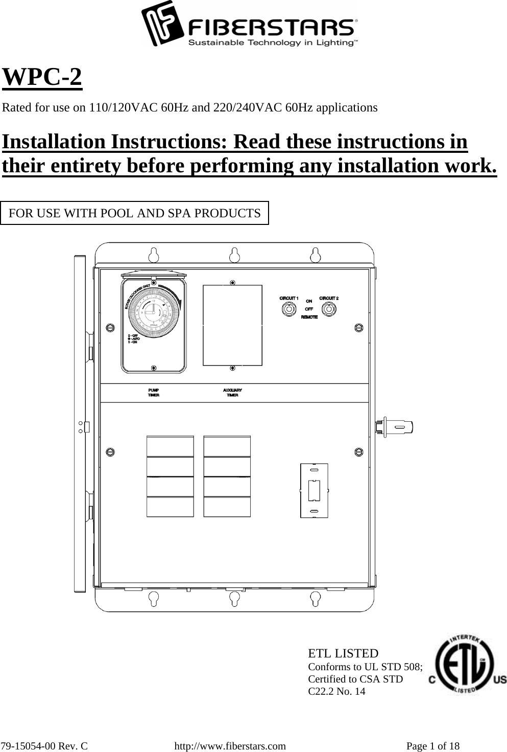
Fiberstars WPC2 WIRELESS CONTROLLER FOR SWIMMING POOL PERIPHERALS User Manual WPC 1
Fiberstars, Inc. WIRELESS CONTROLLER FOR SWIMMING POOL PERIPHERALS WPC 1
UserManual.wiki
>
Fiberstars
>
WPC2 User Manual
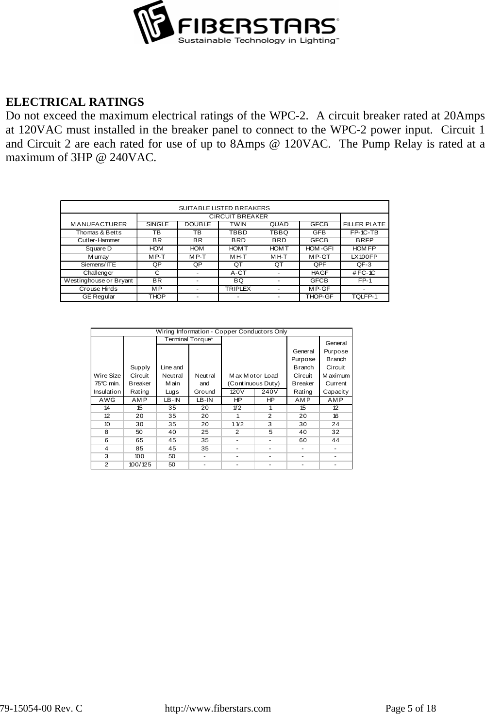
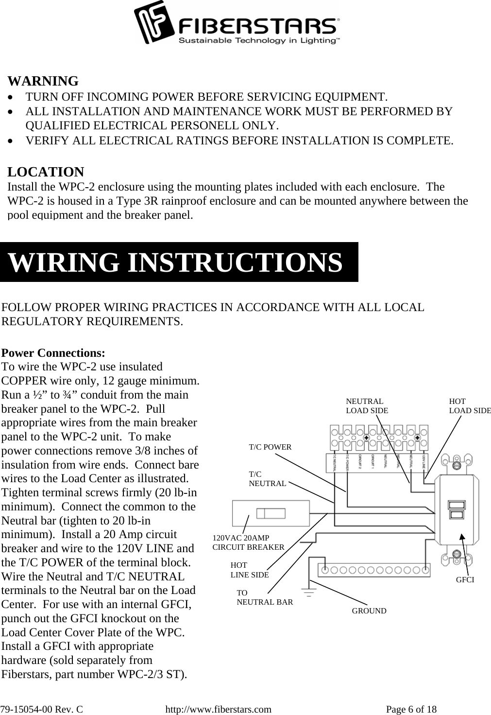
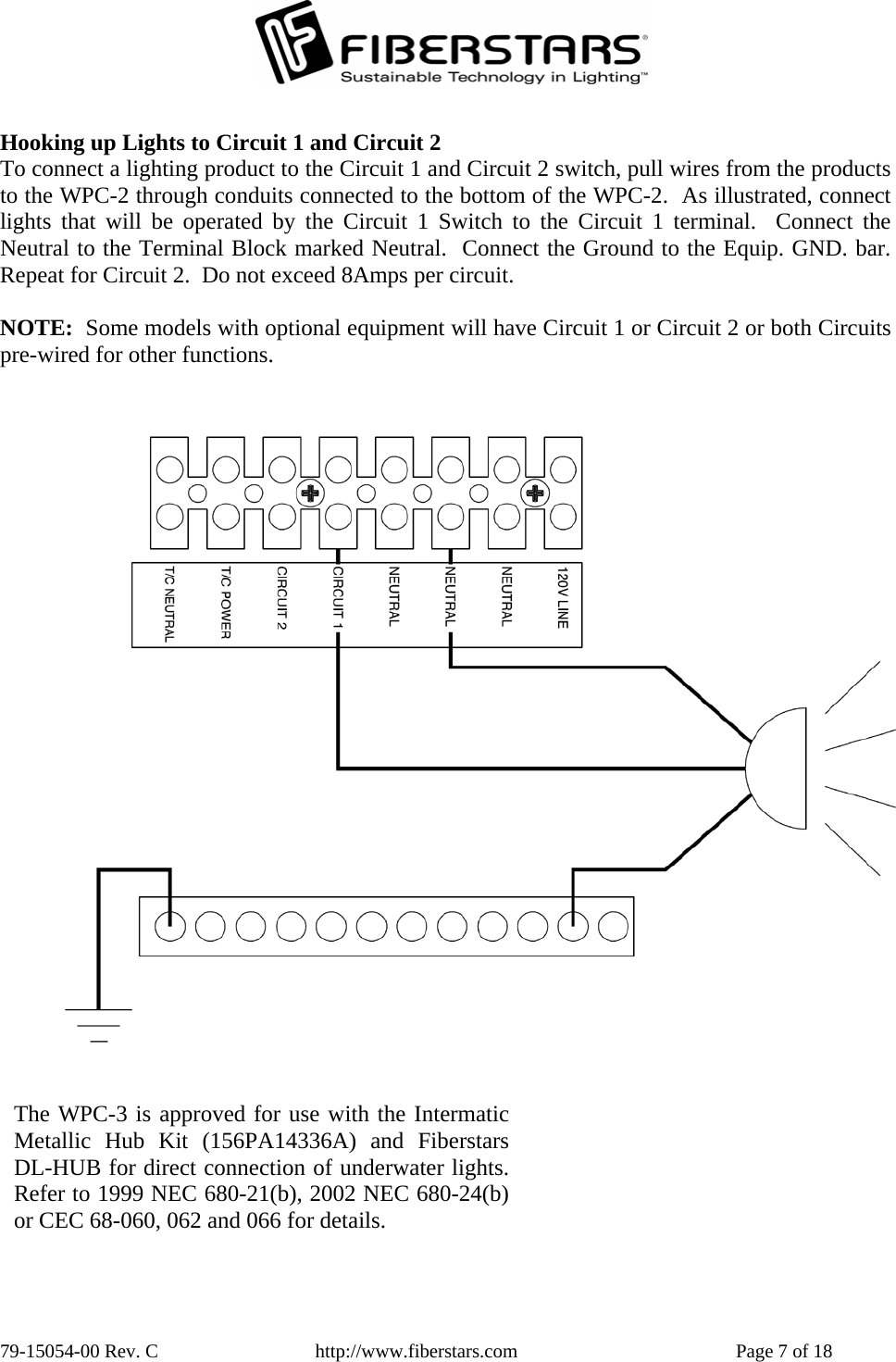
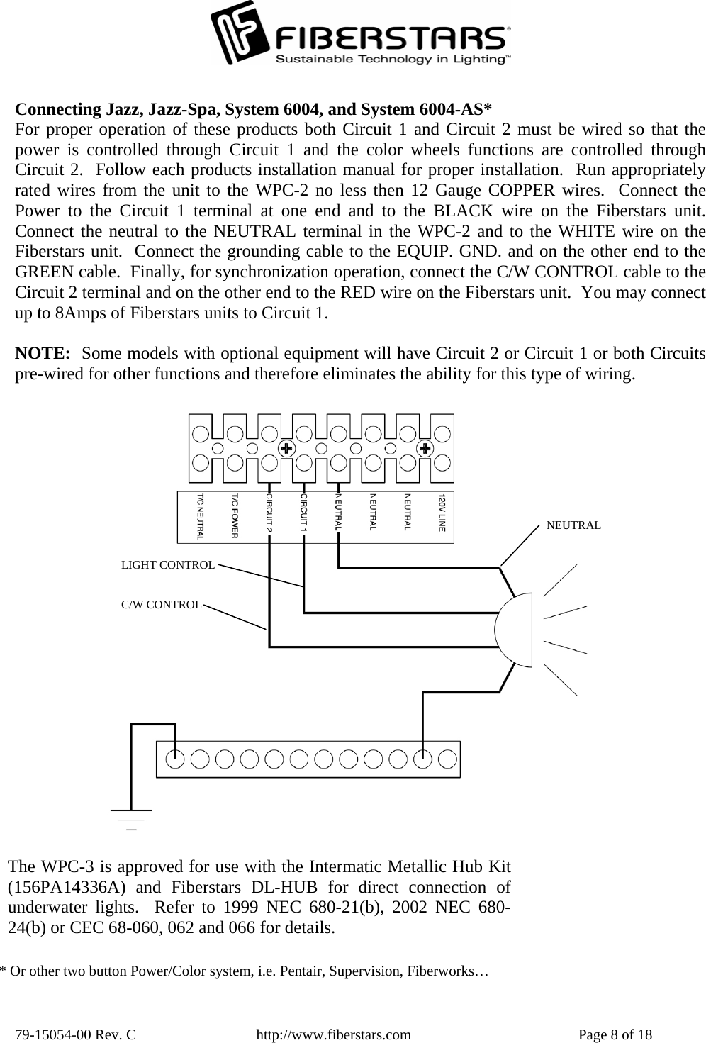
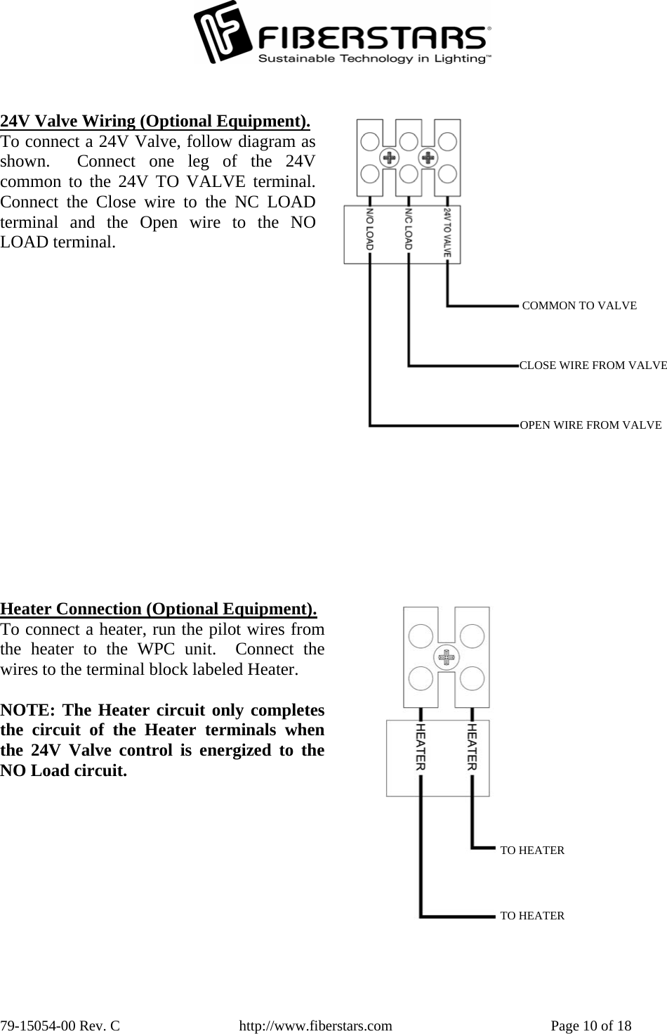
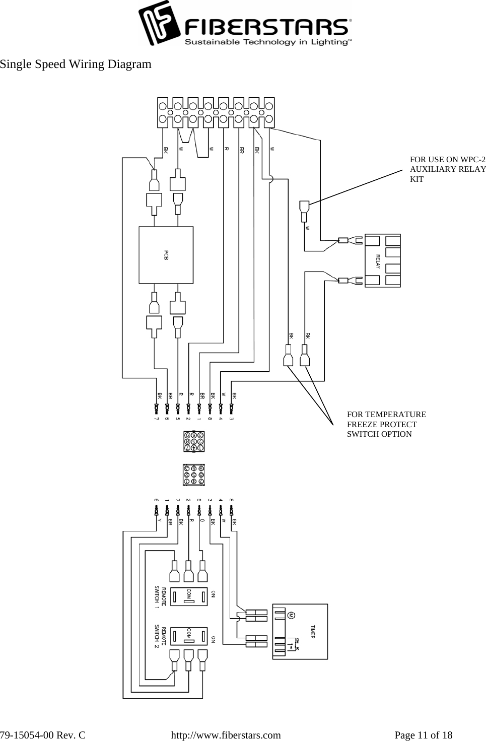
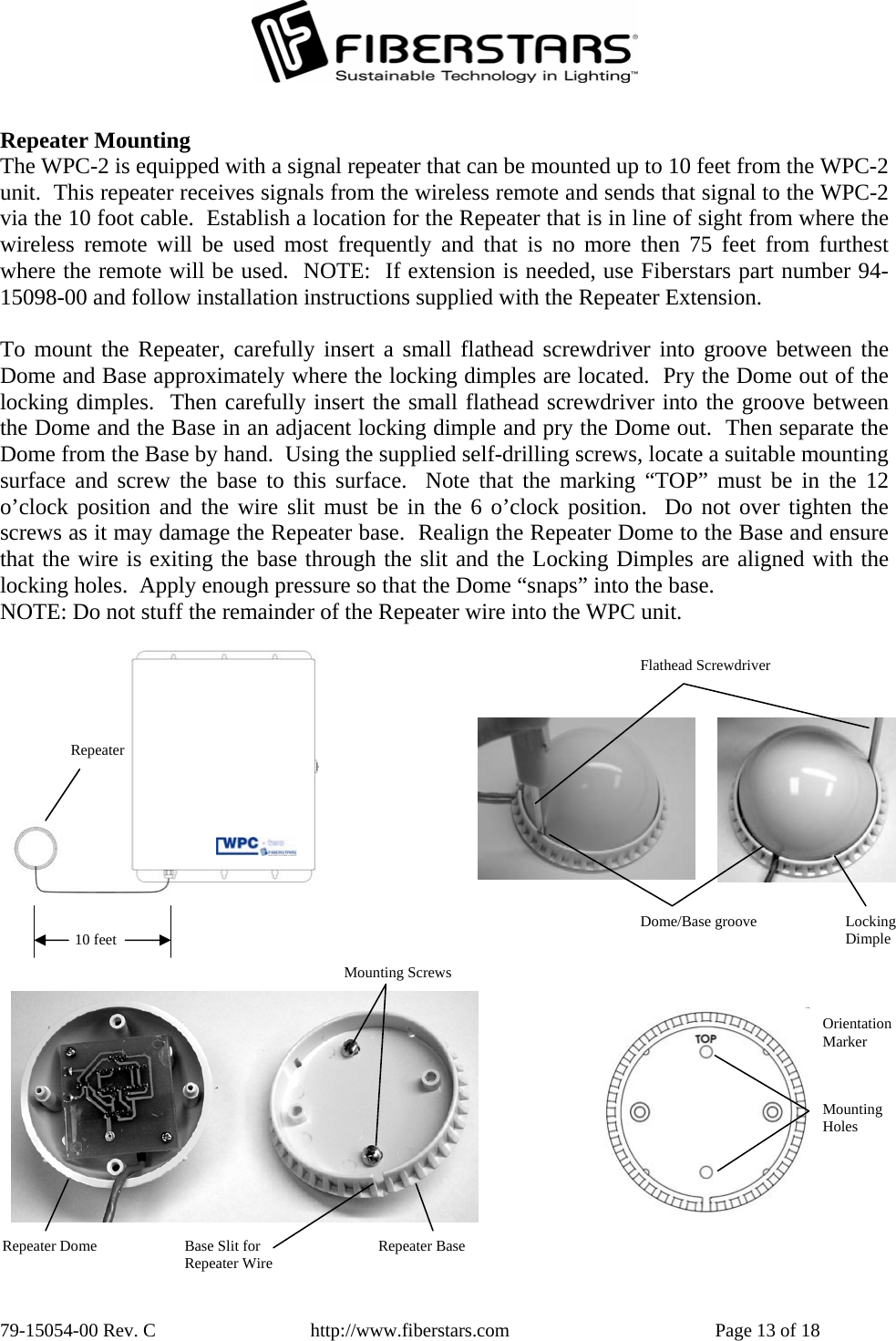
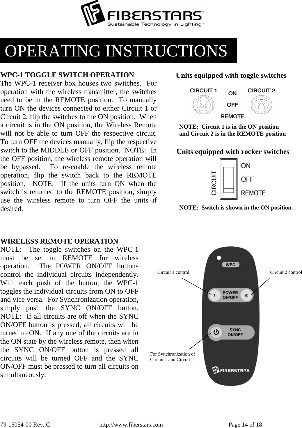
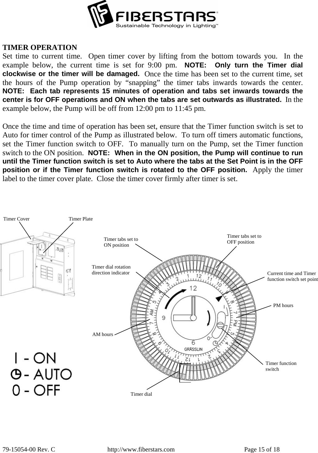
USERS MANUAL
Navigation menu
Upload a User Manual
Namespaces
Wiki Guide
HTML
PDF
Info
Views
User Manual
Discussion / Help
Navigation