Fiberstars WPC2 WIRELESS CONTROLLER FOR SWIMMING POOL PERIPHERALS User Manual WPC 1
Fiberstars, Inc. WIRELESS CONTROLLER FOR SWIMMING POOL PERIPHERALS WPC 1
USERS MANUAL
79-15054-00 Rev. C http://www.fiberstars.com Page 1 of 18
Installation Instructions: Read these instructions in
their entirety before performing any installation work.
Rated for use on 110/120VAC 60Hz and 220/240VAC 60Hz applications
WPC-2
ETL LISTED
Conforms to UL STD 508;
Certified to CSA STD
C22.2 No. 14
FOR USE WITH POOL AND SPA PRODUCTS

79-15054-00 Rev. C http://www.fiberstars.com Page 2 of 18
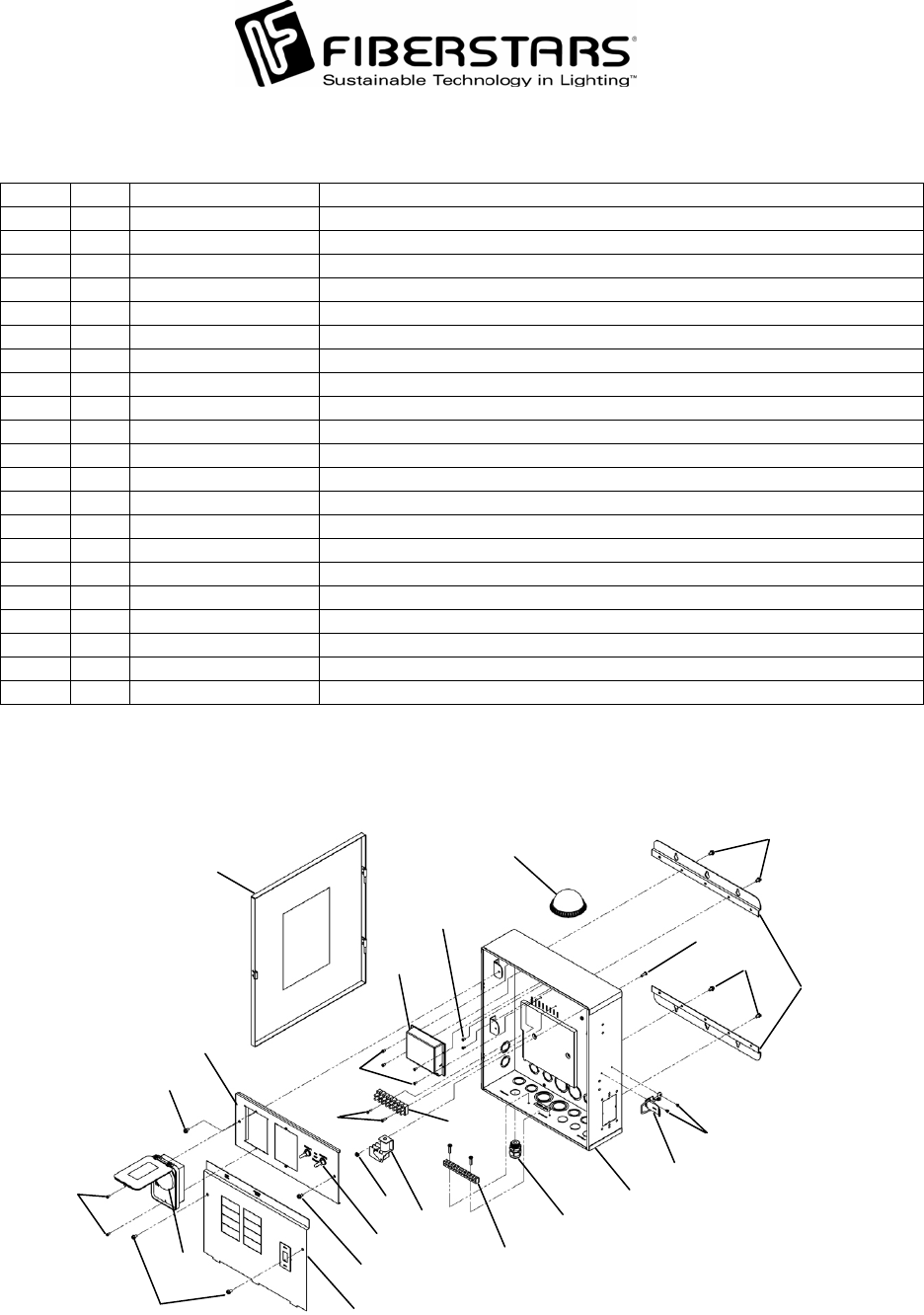
The WPC2 single speed version consists of the following parts:
Item Qty. Component part No. Description
1 1 - WPC-2 Enclosure
2 1 94-15089-00 WPC-2 Enclosure Door
3 1 37-15000-00 Relay
4 1 41-15004-08 8 Position Terminal Block
5 1 42-15032-00 Timer
6 1 02-15269-00 Load Center Cover Plate
7 2 02-15267-00 WPC-2 Mounting Bracket
8 1 41-15003-00 Grounding Bar
9 1 94-15090-00 WPC Receiver
10 8 10-15086-04 Load Center Cover Plate, Switch Bracket, and Mounting Bracket Screws
11 2 10-15089-06 Terminal Block Mounting Screw
12 2 10-15060-01 Relay Mounting Screw
13 8 10-15089-03 Timer and Receiver Mounting Screws
14 2 A11526 3-Position Toggle Switch
15 1 94-15092-00 WPC Repeater
16 2 10-15089-02 Freeze Device Mounting Screw (Optional equipment)
17 1 20-15013-00 Strain Relief
18 1 02-15270-00 Switch Bracket
19 1 17-15005-00 Latch
20 2 10-15089-01 Latch Mounting Screws
Accessory Items:
FP 1/2 Temperature Freeze Device
WE-65 65 ft Repeater Cord Extension Kit
WPC-2/3 ST GFCI Mounting Kit
DL-HUB Direct Light Hub Connection Kit
TC-2 Additional Timeclock/Dust Cover
WPC-12V 12V Transformer for Fiberstars Li
g
ht Streams LED Products
17
16
15
10
18 13
13
11
10
10
9
8
10
7
5
3
12
6
14
10
4
2
1
19
20
79-15054-00 Rev. C http://www.fiberstars.com Page 3 of 18
7
6
19
20
18
17
16
15
10 13
13
11
10
9
8
10
21
4
5
12
14
10
10
3
2
1
The WPC2 dual speed version consists of the following parts:
Item Qty. Component part No. Description
1 1 - WPC-2 Enclosure
2 1 94-15089-00 WPC-2 Enclosure Door
3 1 37-15001-00 DPDT Relay
4 1 41-15004-08 8 Position Terminal Block
5 1 42-15032-00 Timer
6 1 02-15269-00 Load Center Cover Plate
7 2 02-15267-00 WPC-2 Mounting Bracket
8 1 41-15003-00 Grounding Bar
9 1 94-15090-00 WPC Receiver
10 8 10-15086-04 Load Center Cover Plate, Switch Bracket, and Mounting Bracket Screws
11 2 10-15089-06 Terminal Block Mounting Screw
12 1 A7000 Relay Mounting Nut
13 8 10-15089-03 Timer and Receiver Mounting Screws
14 2 A11526 3-Position Toggle Switch
15 1 94-15092-00 WPC Repeater
16 2 10-15089-02 Freeze Device Mounting Screw (Optional equipment)
17 1 20-15013-00 Strain Relief
18 1 02-15270-00 Switch Bracket
19 1 17-15005-00 Latch
20 2 10-15089-01 Latch Mounting Screws
21 1 A8966 Relay Mounting Screw

79-15054-00 Rev. C http://www.fiberstars.com Page 4 of 18
FCC WARNING
1. This device complies with Part 15 of the FCC Rules. Operation is subject to the following two
conditions: (1) this device may not cause harmful interference, and (2) this device must accept
any interference received, including interference that may cause undesired operation.
2. Changes or modifications not expressly approved by Fiberstars Inc. could void the user's
authorit
y
to o
p
erate the e
q
ui
p
ment.
SAVE THESE INSTRUCTIONS!
Basic safety precautions should be observed when operating the WPC-2 product and other
associated equipment.
1. A qualified electrician must install the WPC-2 in accordance to the National and Local
Electrical Codes.
2. The WPC-2 must not be less then 5 feet (3 meters in Canada) from inside edge of pool. ONLY
USE COPPER CONDUCTORS.
3. Do not exceed the maximum ratings of individual components, wiring devices, and current
carrying capacity of conductors.
4. For the bonding, grounding, installing, and wiring of underwater lights to the WPC-2, refer to
Article 680 of the National Electrical Code or Article 68 of the Canadian Electrical Code.
5. This device should never operate an equipment that could cause property damage, bodily
injury, or death should it be activated unexpectedly.
6. Never allow children to operate the WPC-2 unsupervised.
IMPORTANT SAFETY INFORMATION

ELECTRICAL RATINGS
Do not exceed the maximum electrical ratings of the WPC-2. A circuit breaker rated at 20Amps
at 120VAC must installed in the breaker panel to connect to the WPC-2 power input. Circuit 1
and Circuit 2 are each rated for use of up to 8Amps @ 120VAC. The Pump Relay is rated at a
maximum of 3HP @ 240VAC.
SINGLE DOUBLE TWIN QUAD GFCB
Thomas & Betts TB TB TBBD TBBQ GFB FP-1C-TB
Cutler-Hammer BR BR BRD BRD GFCB BRFP
Square D HOM HOM HOM T HOM T HOM -GFI HOM FP
Murray MP-T MP-T MH-T MH-T MP-GT LX100FP
Siemens/ITE QPQPQTQTQPFQF-3
Challenger C - A-CT - HAGF # FC-1C
Westinghouse or Bryant BR - BQ - GFCB FP-1
Crouse Hinds M P - TRIPLEX - M P-GF -
GE Regular THOP - - - THOP-GF TQLFP-1
SUITABLE LISTED BREAKERS
CIRCUIT BREAKER
MANUFACTURER FILLER PLATE
120V 240V
AWG AMP LB-IN LB-IN HP HP AMP AMP
14 15 3 5 2 0 1/ 2 1 15 12
12 20 35 20 1 2 20 16
10 30 35 20 1 1/2 3 30 24
8 504025 2 5 4032
6654535- -6044
4854535- - - -
310050-----
2100/12550-----
General
Purpose
Branch
Circuit
Breaker
Rating
General
Purpose
Branch
Circuit
Maximum
Current
Capacity
Wiring Inf ormation - Copper Conduct ors Only
Terminal Torque*
Wire Size
75°C min.
Insulation
Supply
Circuit
Breaker
Rating
Line and
Neutral
Main
Lugs
Neutral
and
Ground
Max Motor Load
(Continuous Duty)
79-15054-00 Rev. C http://www.fiberstars.com Page 5 of 18

WARNING
• TURN OFF INCOMING POWER BEFORE SERVICING EQUIPMENT.
• ALL INSTALLATION AND MAINTENANCE WORK MUST BE PERFORMED BY
QUALIFIED ELECTRICAL PERSONELL ONLY.
• VERIFY ALL ELECTRICAL RATINGS BEFORE INSTALLATION IS COMPLETE.
LOCATION
Install the WPC-2 enclosure using the mounting plates included with each enclosure. The
WPC-2 is housed in a Type 3R rainproof enclosure and can be mounted anywhere between the
p
ool e
q
ui
p
ment and the breaker
p
anel.
WIRING INSTRUCTIONS
FOLLOW PROPER WIRING PRACTICES IN ACCORDANCE WITH ALL LOCAL
REGULATORY REQUIREMENTS.
Power Connections:
To wire the WPC-2 use insulated
COPPER wire only, 12 gauge m
Run a ½” to ¾” conduit from the ma
breaker panel to the WPC-2. Pull
appropriate wires from the main breaker
panel to the WPC-2 unit. To make
power connections remove 3/8 inches of
insulation from wire ends. Connect b
wires to the Load Center as illustrated.
Tighten terminal screws firmly (20 lb-in
minimum). Connect the common to the
Neutral bar (tighten to 20 lb-in
minimum). Install a 20 Amp circuit
breaker and wire to the 120V LINE a
the T/C POWER of the terminal blo
Wire the Neutral and T/C NEUTRAL
terminals to the Neutral bar on the Load
Center. For use with an internal GFCI,
punch out the GFCI knockout on the
Load Center Cover Plate of the WPC
Install a GFCI with appropriate
hardware (sold separately from
Fiberstars, part number WPC-2/3 ST).
in
are
nd
ck.
.
TO
N
EUTRAL BAR
DE
GROUND
HOT
LINE SI
T/C
N
EUTRAL
T/C POWER
HOT
LOAD SIDE
N
EUTRAL
LOAD SIDE
GFCI
120VAC 20AMP ERCIRCUIT BREAK
inimum.
79-15054-00 Rev. C http://www.fiberstars.com Page 6 of 18
79-15054-00 Rev. C http://www.fiberstars.com Page 7 of 18
The WPC-3 is approved for use with the Intermatic
Metallic Hub Kit (156PA14336A) and Fiberstars
DL-HUB for direct connection of underwater lights.
Refer to 1999 NEC 680-21(b), 2002 NEC 680-24(b)
or CEC 68-060, 062 and 066 for details.
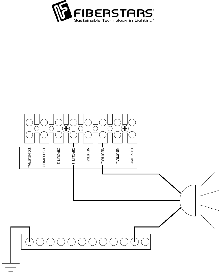
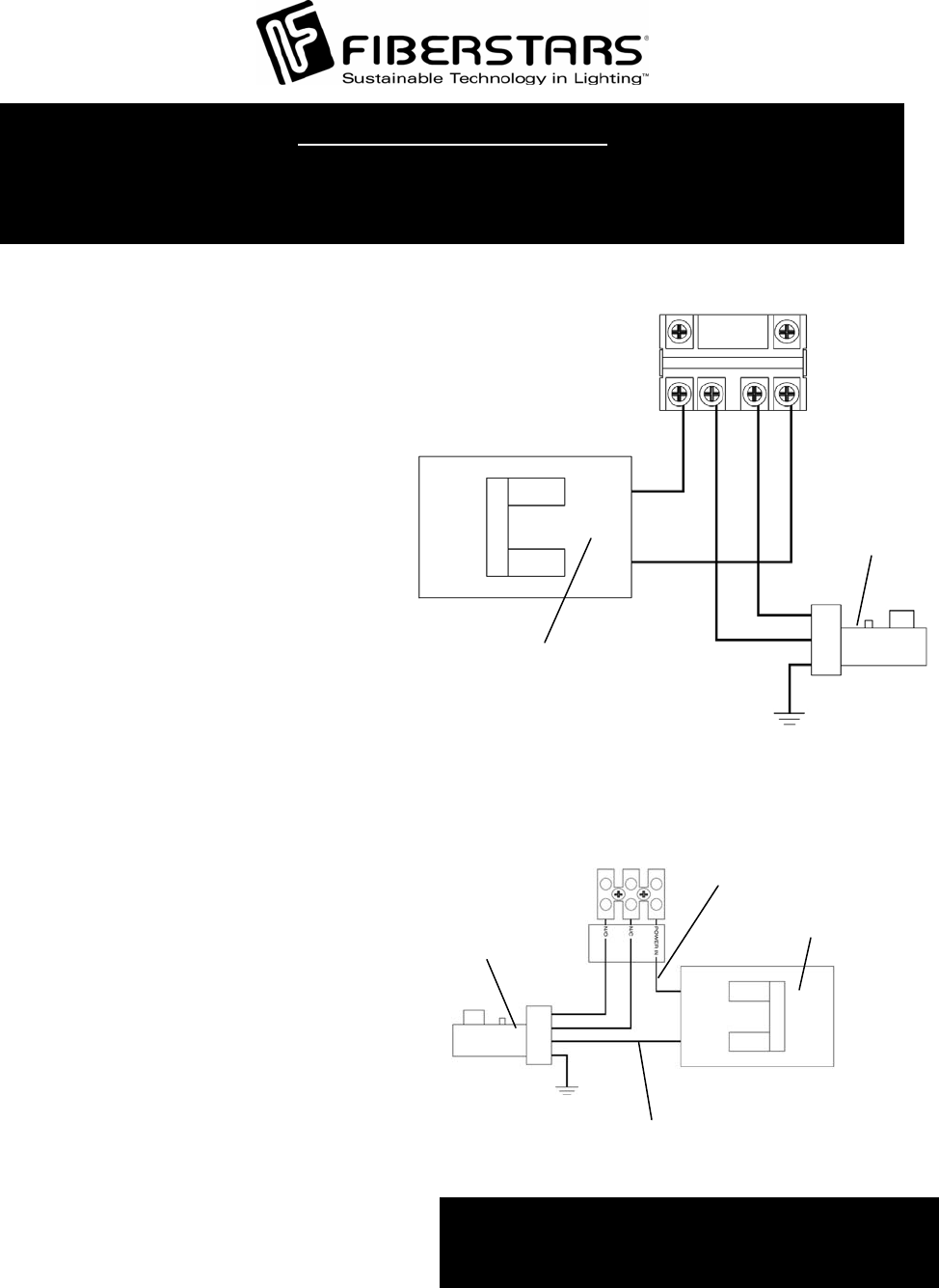
Hooking up Lights to Circuit 1 and Circuit 2
To connect a lighting product to the Circuit 1 and Circuit 2 switch, pull wires from the products
to the WPC-2 through conduits connected to the bottom of the WPC-2. As illustrated, connec
t
lights that will be operated by the Circuit 1 Switch to the Circuit 1 terminal. Connect the
N
eutral to the Terminal Block marked Neutral. Connect the Ground to the Equip. GND. bar.
Repeat for Circuit 2. Do not exceed 8Amps per circuit.
NOTE: Some models with optional equipment will have Circuit 1 or Circuit 2 or both Circuits
p
re-wired for other functions.
79-15054-00 Rev. C http://www.fiberstars.com Page 8 of 18
C/W CONTROL
LIGHT CONTROL
N
EUTRAL
The WPC-3 is approved for use with the Intermatic Metallic Hub Kit
(156PA14336A) and Fiberstars DL-HUB for direct connection o
f
underwater lights. Refer to 1999 NEC 680-21(b), 2002 NEC 680-
24(b) or CEC 68-060, 062 and 066 for details.
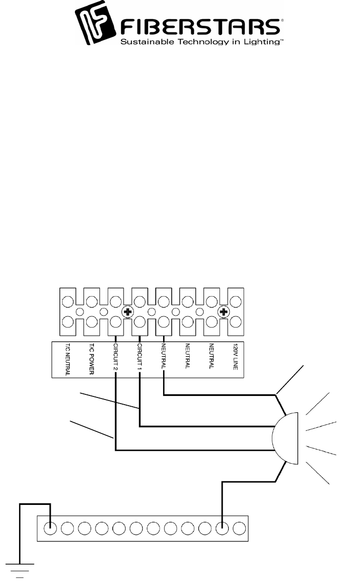
Connecting Jazz, Jazz-Spa, System 6004, and System 6004-AS*
For proper operation of these products both Circuit 1 and Circuit 2 must be wired so that the
p
ower is controlled through Circuit 1 and the color wheels functions are controlled through
Circuit 2. Follow each products installation manual for proper installation. Run appropriately
rated wires from the unit to the WPC-2 no less then 12 Gauge COPPER wires. Connect the
Power to the Circuit 1 terminal at one end and to the BLACK wire on the Fiberstars unit.
Connect the neutral to the NEUTRAL terminal in the WPC-2 and to the WHITE wire on the
Fiberstars unit. Connect the grounding cable to the EQUIP. GND. and on the other end to the
GREEN cable. Finally, for synchronization operation, connect the C/W CONTROL cable to the
Circuit 2 terminal and on the other end to the RED wire on the Fiberstars unit. You may connec
t
up to 8Amps of Fiberstars units to Circuit 1.
NOTE: Some models with optional equipment will have Circuit 2 or Circuit 1 or both Circuits
p
re-wired for other functions and therefore eliminates the ability for this type of wiring.
* Or other two button Power/Color system, i.e. Pentair, Supervision, Fiberworks…
79-15054-00 Rev. C http://www.fiberstars.com Page 9 of 18
HI SPEED
LO SPEED
POWER IN
120V SECONDARY CONNECTED
TO 2 SPEED PUMP
240VAC CIRCUIT
BREAKER
2 SPEED PUMP
120V PRIMARY
NOTE: Pump Breaker MUST be turned OFF
before servicing as 2nd leg of 240V
circuit is HOT at all time!
CONNECTING A 240VAC DUAL
SPEED PUMP
As illustrated, connect the Low Spee
d
wire to the Low Speed Load terminal o
n
the terminal block. Connect the High
Speed wire to the High Speed Loa
d
terminal on the terminal block. Connec
t
the 120V Primary from the 240V Circuit
Breaker to the 120V PRI INPUT terminal.
Directly connect the 120V Secondary
from the Circuit Breaker to the 2 Spee
d
Pump.
NOTE: The Secondary 120V must be
directly connected to the
pump for 240V operation.
240VAC Pump
240V Circuit
Breaker
CONNECTING A 240VAC PUMP
Connect a 240V 30AMP Circuit Breake
r
for each pump (if this control box is
equipped with optional pump relays).
Using an appropriately sized copper
wires connect to the outer contacts of the
JQX relays of the appropriate pumps as
shown. Run wires from the pump to the
inner contacts of the appropriate JQX
relay.
NOTE: This unit maybe equipped with
more then one JQX relay for pump
control.
PUMP CONNECTIONS
NOTE: Some models are ONLY equipped with Single Speed OR Dual Speed pump
connections.
79-15054-00 Rev. C http://www.fiberstars.com Page 10 of 18
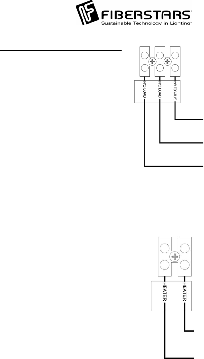
TO HEATER
TO HEATER
Heater Connection (Optional Equipment).
To connect a heater, run the pilot wires from
the heater to the WPC unit. Connect the
wires to the terminal block labeled Heater.
NOTE: The Heater circuit onl
y
completes
the circuit of the Heater terminals when
the 24V Valve control is ener
g
ized to the
NO Load circuit.
OPEN WIRE FROM VALVE
CLOSE WIRE FROM VALVE
COMMON TO VALVE
24V Valve Wiring (Optional Equipment).
To connect a 24V Valve, follow diagram as
shown. Connect one leg of the 24V
common to the 24V TO VALVE terminal.
Connect the Close wire to the NC LOAD
terminal and the Open wire to the NO
LOAD terminal.
79-15054-00 Rev. C http://www.fiberstars.com Page 11 of 18
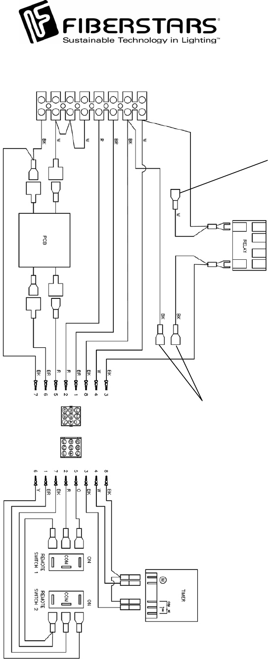
Single Speed Wiring Diagram
FOR USE ON WPC-2
AUXILIARY RELAY
KIT
FOR TEMPERATURE
FREEZE PROTECT
SWITCH OPTION
79-15054-00 Rev. C http://www.fiberstars.com Page 12 of 18
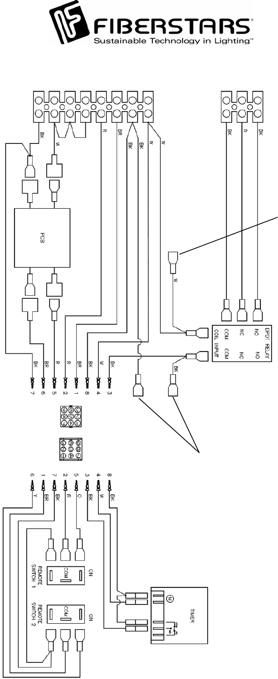
Dual Speed Wiring Diagram
FOR USE ON WPC-2
AUXILIARY RELAY
KIT
FOR TEMPERATURE
FREEZE PROTECT
SWITCH OPTION
79-15054-00 Rev. C http://www.fiberstars.com Page 13 of 18
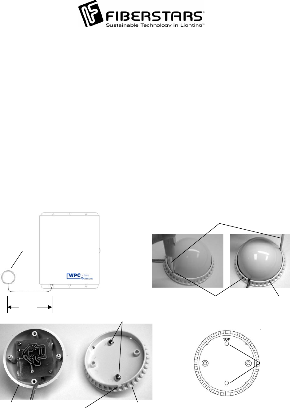
Repeater Dome
Repeater Mounting
The WPC-2 is equipped with a signal repeater that can be mounted up to 10 feet from the WPC-2
unit. This repeater receives signals from the wireless remote and sends that signal to the WPC-2
via the 10 foot cable. Establish a location for the Repeater that is in line of sight from where the
wireless remote will be used most frequently and that is no more then 75 feet from furthest
where the remote will be used. NOTE: If extension is needed, use Fiberstars part number 94-
15098-00 and follow installation instructions supplied with the Repeater Extension.
To mount the Repeater, carefully insert a small flathead screwdriver into groove between the
Dome and Base approximately where the locking dimples are located. Pry the Dome out of the
locking dimples. Then carefully insert the small flathead screwdriver into the groove betwee
n
the Dome and the Base in an adjacent locking dimple and pry the Dome out. Then separate the
Dome from the Base by hand. Using the supplied self-drilling screws, locate a suitable mounting
surface and screw the base to this surface. Note that the marking “TOP” must be in the 12
o’clock position and the wire slit must be in the 6 o’clock position. Do not over tighten the
screws as it may damage the Repeater base. Realign the Repeater Dome to the Base and ensure
that the wire is exiting the base through the slit and the Locking Dimples are aligned with the
locking holes. Apply enough pressure so that the Dome “snaps” into the base.
N
OTE: Do not stuff the remainder of the Repeater wire into the WPC unit.
Flathead Screwdriver
Dome/Base groove Locking
Dimple
10 feet
Repeater
Orientation
Marker
Mounting
Holes
Mounting Screws
Repeater Base Base Slit for
Repeater Wire
79-15054-00 Rev. C http://www.fiberstars.com Page 14 of 18
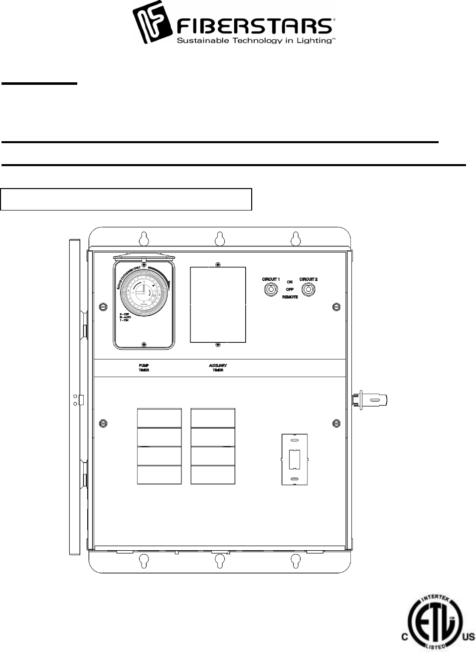
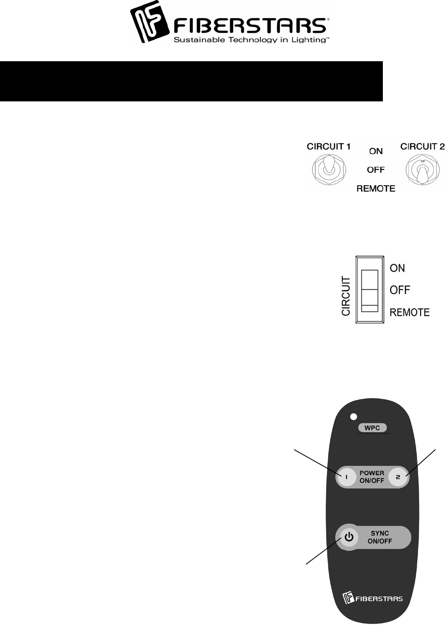
Units equipped with rocker switches
NOTE: Switch is shown in the ON position.
Units equipped with toggle switches
NOTE: Circuit 1 is in the ON position
and Circuit 2 is in the REMOTE position
WPC-1 TOGGLE SWITCH OPERATION
The WPC-1 receiver box houses two switches. Fo
r
operation with the wireless transmitter, the switches
need to be in the REMOTE position. To manually
turn ON the devices connected to either Circuit 1 o
r
Circuit 2, flip the switches to the ON position. When
a circuit is in the ON position, the Wireless Remote
will not be able to turn OFF the respective circuit.
To turn OFF the devices manually, flip the respective
switch to the MIDDLE or OFF position. NOTE: I
n
the OFF position, the wireless remote operation will
be bypassed. To re-enable the wireless remote
operation, flip the switch back to the REMOTE
p
osition. NOTE: If the units turn ON when the
switch is returned to the REMOTE position, simply
use the wireless remote to turn OFF the units i
f
desired.
OPERATING INSTRUCTIONS
For Synchronization of
Circuit 1 and Circuit 2
Circuit 2 control Circuit 1 control
WIRELESS REMOTE OPERATION
N
OTE: The toggle switches on the WPC-1
must be set to REMOTE for wireless
operation. The POWER ON/OFF buttons
control the individual circuits independently.
With each push of the button, the WPC-1
toggles the individual circuits from ON to OFF
and vice versa. For Synchronization operation,
simply push the SYNC ON/OFF button.
N
OTE: If all circuits are off when the SYNC
ON/OFF button is pressed, all circuits will be
turned to ON. If any one of the circuits are in
the ON state by the wireless remote, then when
the SYNC ON/OFF button is pressed all
circuits will be turned OFF and the SYNC
ON/OFF must be pressed to turn all circuits on
simultaneously.
79-15054-00 Rev. C http://www.fiberstars.com Page 15 of 18
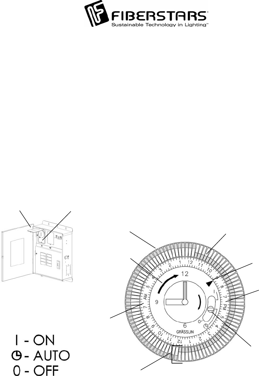
PM hours
TIMER OPERATION
Set time to current time. Open timer cover by lifting from the bottom towards you. In the
example below, the current time is set for 9:00 pm. NOTE: Only turn the Timer dial
clockwise or the timer will be damaged. Once the time has been set to the current time, set
the hours of the Pump operation by “snapping” the timer tabs inwards towards the center.
NOTE: Each tab represents 15 minutes of operation and tabs set inwards towards the
center is for OFF operations and ON when the tabs are set outwards as illustrated. In the
example below, the Pump will be off from 12:00 pm to 11:45 pm.
Once the time and time of operation has been set, ensure that the Timer function switch is set to
Auto for timer control of the Pump as illustrated below. To turn off timers automatic functions,
set the Timer function switch to OFF. To manually turn on the Pump, set the Timer function
switch to the ON position. NOTE: When in the ON position, the Pump will continue to run
until the Timer function switch is set to Auto where the tabs at the Set Point is in the OFF
position or if the Timer function switch is rotated to the OFF position. Apply the time
r
label to the timer cover plate. Close the timer cover firmly after timer is set.
Timer Cover Timer Plate
Timer tabs set to
OFF position
Timer tabs set to
ON position
Timer dial rotation
direction indicator Current time and Timer
function switch set point
Timer function
switch
Timer dial
AM hours
79-15054-00 Rev. C http://www.fiberstars.com Page 16 of 18
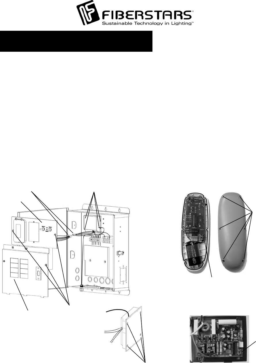
Receiver
screws
DIP switch
Rear screws
DIP Switch
Load Center
Cover Plate
Molex Connector
Switch Bracket
Mounting
Screws
Receiver Mounting
Holes
If it is necessary to change the transmission code on the WPC-2 an adjustment to the receiver AND the transmitte
r
DIP switches must be performed.
RECEIVER DIP SWITCHES – Turn OFF power to the WPC-2 from the circuit breaker on the Load Center o
r
from Main Power. Open the enclosure door. Unscrew and remove the Load Center Cover Plate. Place the Cove
r
Bracket in a safe location. Unscrew and remover the Switch Bracket. Disconnect the Molex connector tha
t
connects the Switch Bracket controls to the receiver unit and set the Switch Bracket in a safe location where it will
not be bent, scratched, or impact forces applied to the components or the face plate itself. Unscrew the four (4)
screws holding the receiver to the base of the WPC-2 control box. Unscrew the four (4) screws located on the
b
ack of the receiver to release the cover. NOTE: Take notice of how the wires enter and exit the receiver.
Remove the cover and look on the PCB to locate the DIP switch as illustrated.
TRANSMITTER DIP SWITCHES – Remove all screws from rear of remote. Separate the bottom cover from the
top cover.
DIP SWITCH ADJUSTMENT – The four DIP switches have an ON and an OFF position. Changing just one DIP
switch will change the code. MAKE SURE BOTH THE RECEIVER AND TRANSMITTER HAVE THE SAME
DIP SWITCH SETTINGS.
CODE ADJUSTMENTS

79-15054-00 Rev. C http://www.fiberstars.com Page 17 of 18
Note: Sample shown is of Channel 9
DIP SWITCH1234
Channel 1 OFF OFF OFF OFF
Channel 2 ON OFF OFF OFF
Channel 3 OFF ON OFF OFF
Channel 4 ON ON OFF OFF
Channel 5 OFF OFF ON OFF
Channel 6 ON OFF ON OFF
Channel 7 OFF ON ON OFF
Channel 8ONONONOFF
Channel 9 OFF OFF OFF ON
Channel 10 ON OFF OFF ON
Channel 11 OFF ON OFF ON
Channel 12 ON ON OFF ON
Channel 13 OFF OFF ON ON
Channel 14 ON OFF ON ON
Channel 15 OFF ON ON ON
Channel 16 ON ON ON ON
DIP Switch
CHANNEL
15913
2 6 10 14
3 7 11 15
4 8 12 16
WPC FUNCTION CHART
Below is a chart of the WPC functionality based on the model number.
WPC2 - -
Pump
Features Button 1
Features Button 2
Features Other
Options Accessories
X – Standard
1 – Load Center
Removed
X – Standard
1 – T/C Bypass
2 – T/C Bypass & JVA Valve
3 – WFPR added for Booster Pump
X – Standard
3 – WFPR added for Booster
Pump
X –1 Speed Pump – Standard
2 – 2 Speed Pump – 24/7 LO Speed,
T/C controls HI Speed
3 – 2 Speed Pump w/T.C. for Lo Speed
& T/C for Hi Speed
X – Standard
1 – Freeze Protect
2 – T/C w/Relay for
Pool Booster Pump
Cleaner
5 – FP & T/C w/Relay
for Pool Cleaner
Pump
EXAMPLE:
WPC2-2X2X-1 is a 2 speed pump model with the Low Speed ON continuously until High
Speed is actuated by the Time Clock. Button 1/Circuit 1 is wired standard. Button 2/Circuit 2 is
wired as a Time Clock Bypass & JVA which actuates a JVA valve and turns on the High Speed
pump (if Time Clock is already ON, then this action will keep the High Speed ON even after the
Time Clock has Shut OFF) with the push of the Button 2 on the remote or flipping the Circuit 2
switch to ON. And this equipment is equipped with a Freeze Protect device which will turn on
the High Speed pump when outside temperatures drop near freezing.
79-15054-00 Rev. C http://www.fiberstars.com Page 18 of 18