Fidelity Comtech FCI3100X Phased Array WLAN Terminal User Manual Phocus 2 1 Beta 3
Fidelity Comtech, Inc. Phased Array WLAN Terminal Phocus 2 1 Beta 3
Contents
- 1. User Manual Part One
- 2. User Manual Part Two
- 3. User Manual Part Three
User Manual Part Three
Phocus Array System Manual v2.1
55
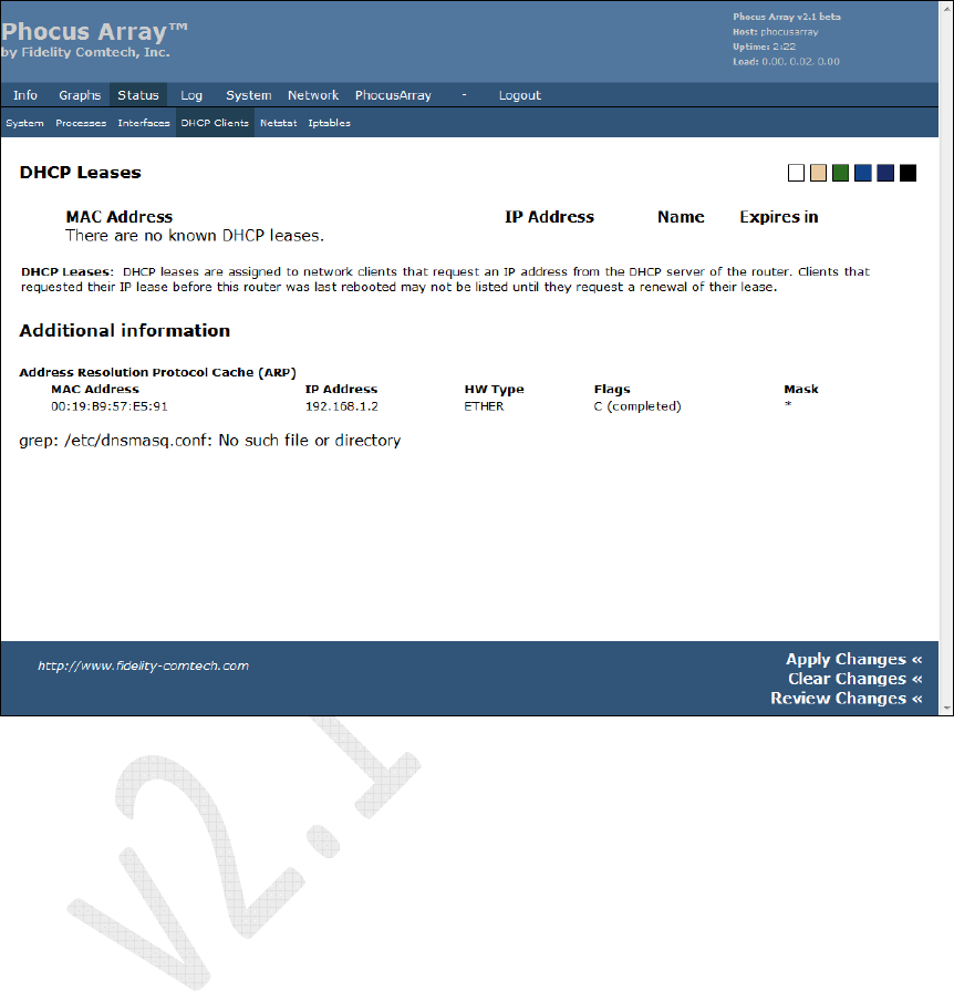
5.4.4 DHCP Clients
The screen displays information about any DHCP Leases and information such as
Address Resolution Protocol Cache.
Figure 35 – DHCP Clients
Phocus Array System Manual v2.1
56
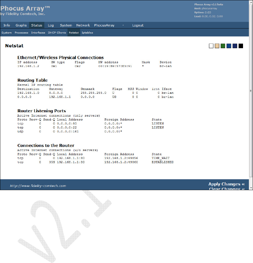
5.4.5 Netstat
The screen displays Ethernet/Wireless Physical Connections, Routing Table,
Router Listening Ports, and Connections to the Router.
Figure 36 – Netstat
Phocus Array System Manual v2.1
57
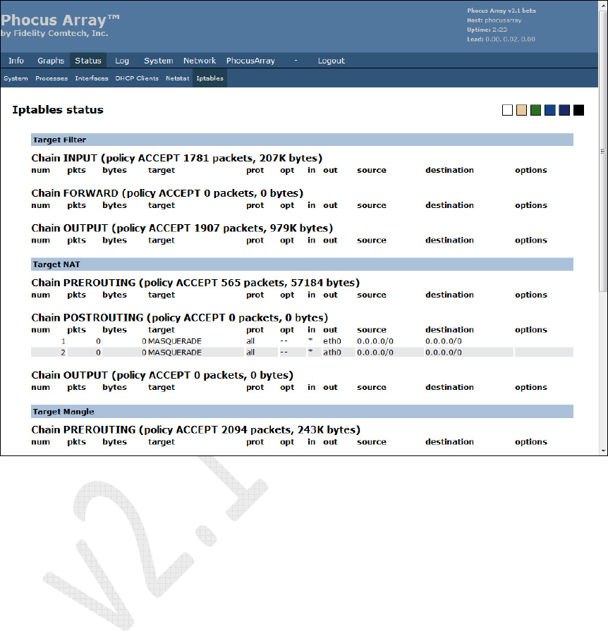
5.4.6 Iptables
The screen displays the status for each Iptable, including Target filter, Target NAT,
and Target Mangle.
Figure 37 – Iptables
Phocus Array System Manual v2.1
58
5.5 Log Tab
The Log menu contains the following tabs:
• Syslog Settings – remote syslog, syslog marks, local log
• Syslog – syslog view
• Kernel – kernel ring buffer
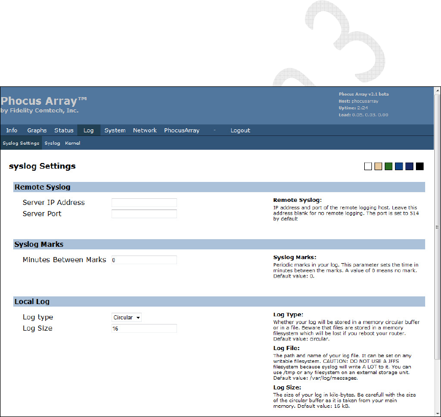
5.5.1 Syslog Settings
This screen allows the system administrator to set up “syslogs”. It permits
administrators to direct the system’s syslog to be routed to a remote system. This
permits archiving of historical system activity.
Enter the Server IP Address and Server Port into the appropriate fields. The remote
server receives a continuous stream of log entries. The Local Log controls affect the
entries that are views under the Syslog tab.
Figure 38 – Syslog Settings
Phocus Array System Manual v2.1
59
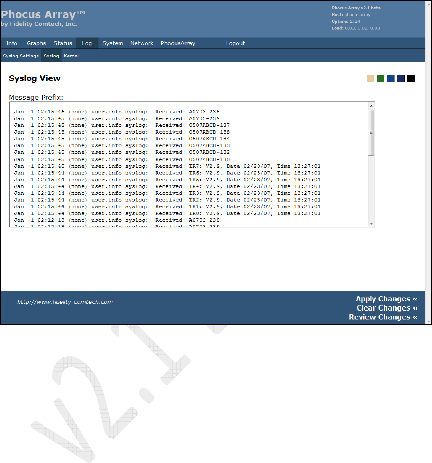
5.5.2 Syslo
This screen provides a view of the historical syslog.
Figure 39 – Syslog View
Phocus Array System Manual v2.1
60
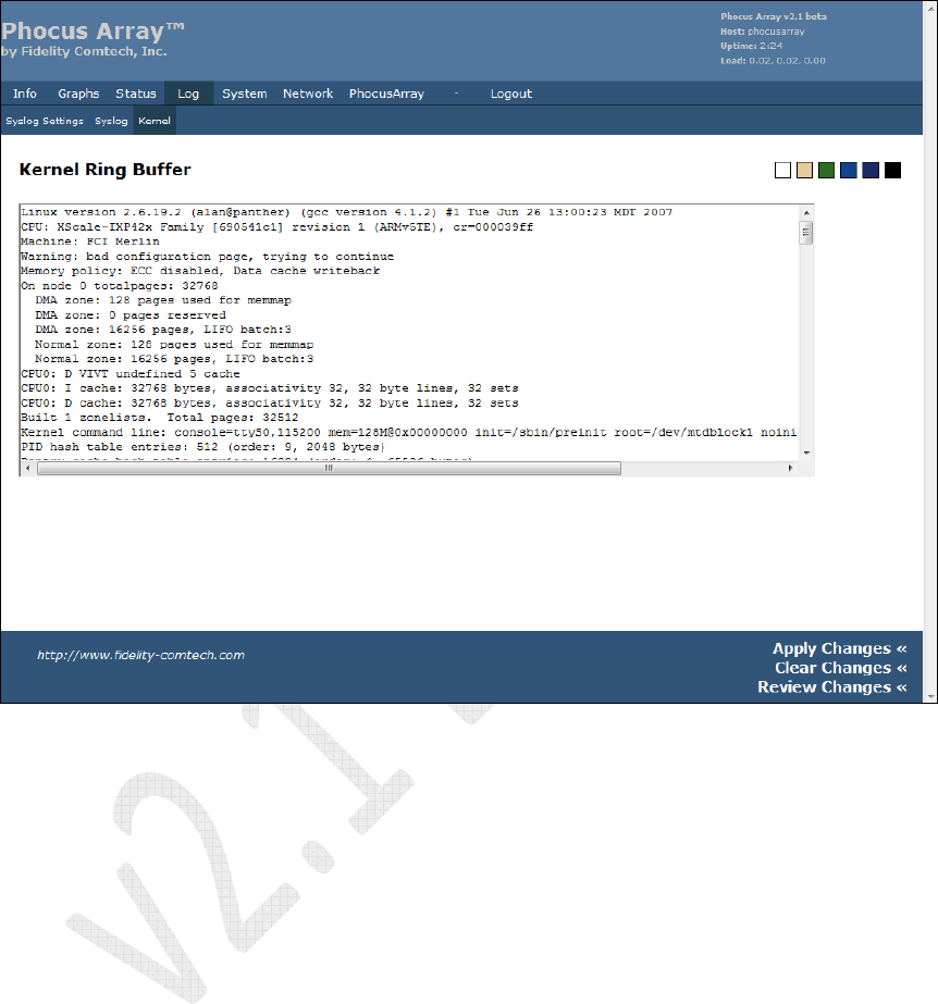
5.5.3 Kernel
This screen displays a record of the Kernel Ring Buffer .
Figure 40 – Kernel Ring Buffer
Phocus Array System Manual v2.1
61
5.6 System Tab
The System menu contains the following tabs:
• Settings – system settings, time settings, Webif
2
settings
• Password – password change
• Backup and Restore – options to backup or restore configuration and
entire flash
• Upgrade – UpGrade Phocus Array System firmware
• Reboot
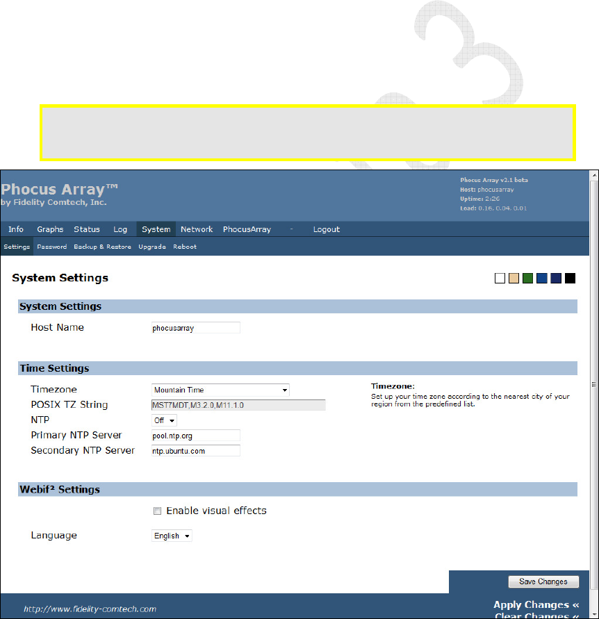
5.6.1 Settings
Use this screen to enter a Host Name for the Phocus Array System, set the Timezone
and NTP Servers, and select Webif
2
Settings.
Limits/caution: Only letters and numerals may be used for the
Host Name
(a-z, A-Z and 0-
9).
No spaces or special characters may be used.
Figure 41 – System Settings
Phocus Array System Manual v2.1
62
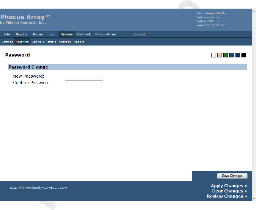
5.6.2 Password
Use this screen to change the password.
Password guidelines include using:
•
Eight (8) or more characters including letters, numerals and non-alphanumeric
characters.
•
Uppercase on more than the first letter. Passwords are case sensitive.
•
The first letter from each word in a phrase (e.g., C$200wpG, represents
"Collect $200 when passing Go").
Figure 42 – Password Change
Phocus Array System Manual v2.1
63
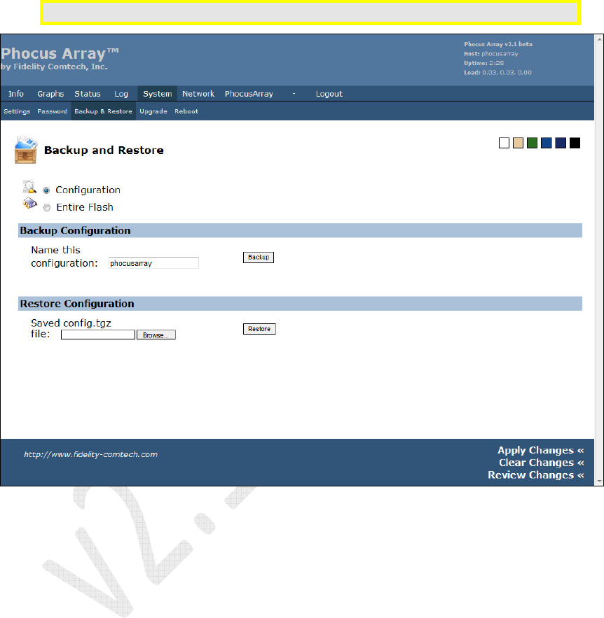
5.6.3 Backup and Restore
Use this screen to perform routine backup of files and to restore previous
configurations. Most users should only backup their Configuration.
Caution: Do not backup or restore the
Entire Flash
. This is for development use only
Figure 43 – Backup and Restore
Phocus Array System Manual v2.1
64
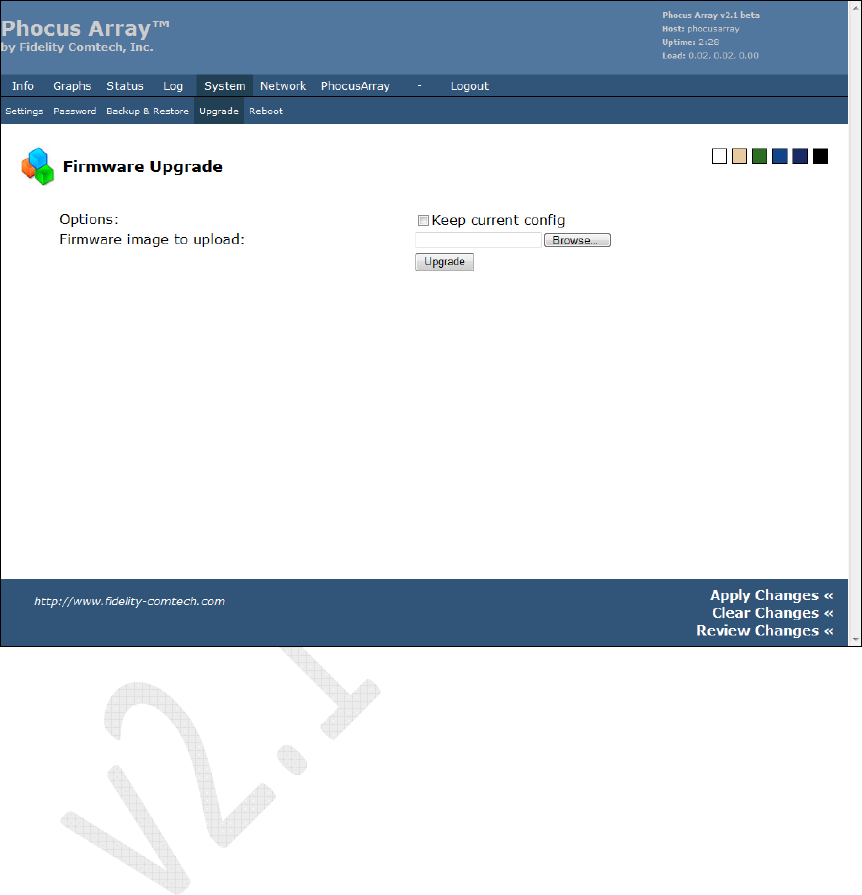
5.6.4 Uploading Firmware UpDates or UpGrades
Use this screen to upload Phocus Array System firmware UpDates or UpGrades when
provided by Fidelity Comtech, Inc. or an FCI Authorized Channel Partner.
Figure 44 – Firmware Uploads
Phocus Array System Manual v2.1
65
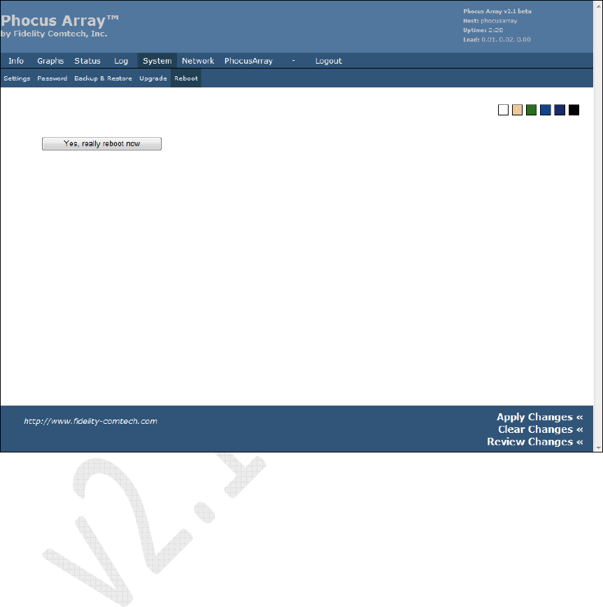
5.6.5 Reboot
Use this screen to reboot the Phocus Array System. The system will be taken out of
service for about two minutes when rebooted. It boots to the last saved/applied
configuration.
Figure 45 – Reboot
Phocus Array System Manual v2.1
66
5.7
Network Tab
The Network menu contains the following tabs:
• Configuration – system configuration, wired and wireless configuration,
gateway, and DNS server
• Wireless – wireless adapter wifi0 configuration, wireless virtual adapter
configuration for wireless card wifi0
• DHCP Server – configuration of DHCP server for LAN
• Hosts – host names, static IP addresses (for DHCP)
• Tweaks – networking tweaks, conntrack settings
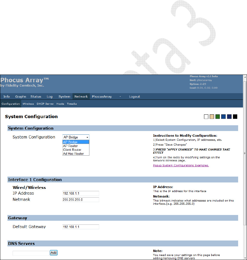
5.7.1 Configuration
Use this screen to configure the overall function of the Phocus Array System as an AP
Bridge, AP Router, Client Router, or Ad Hoc Router. Once a system function is
selected, the appropriate fields in the lower parts of the screen can be completed with
information for your application. The Wired and Wireless interfaces can be
configured with static IP addresses.
Figure 46 – System Configuration
Phocus Array System Manual v2.1
67
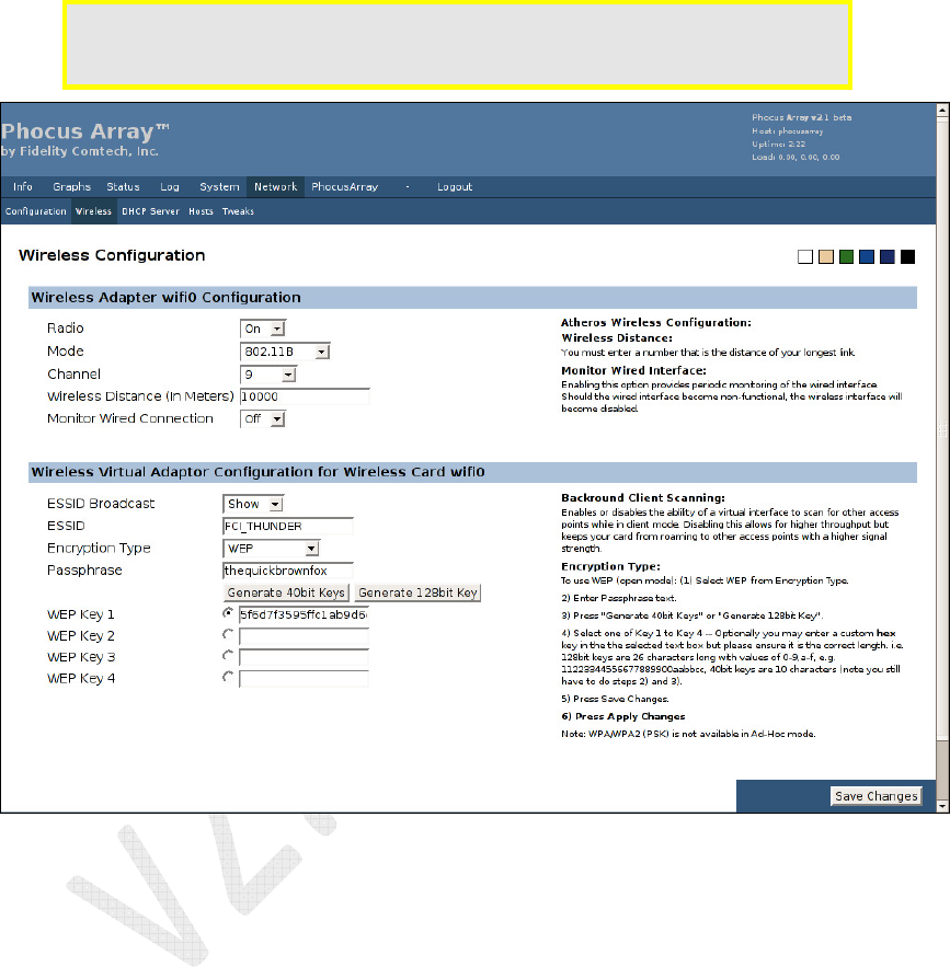
5.7.2 Wireless
Use this screen to configure Wireless Adapter wifi0 or Wireless Virtual adapter for
Wireless Card wifi0.
Caution: Modification of the
Encryption Type
requires the Phocus Array System to
be rebooted. After saving and applying changes, you must reboot the
system for the new encryption settings to take effect.
Figure 47 – Wireless Configuration
Phocus Array System Manual v2.1
68
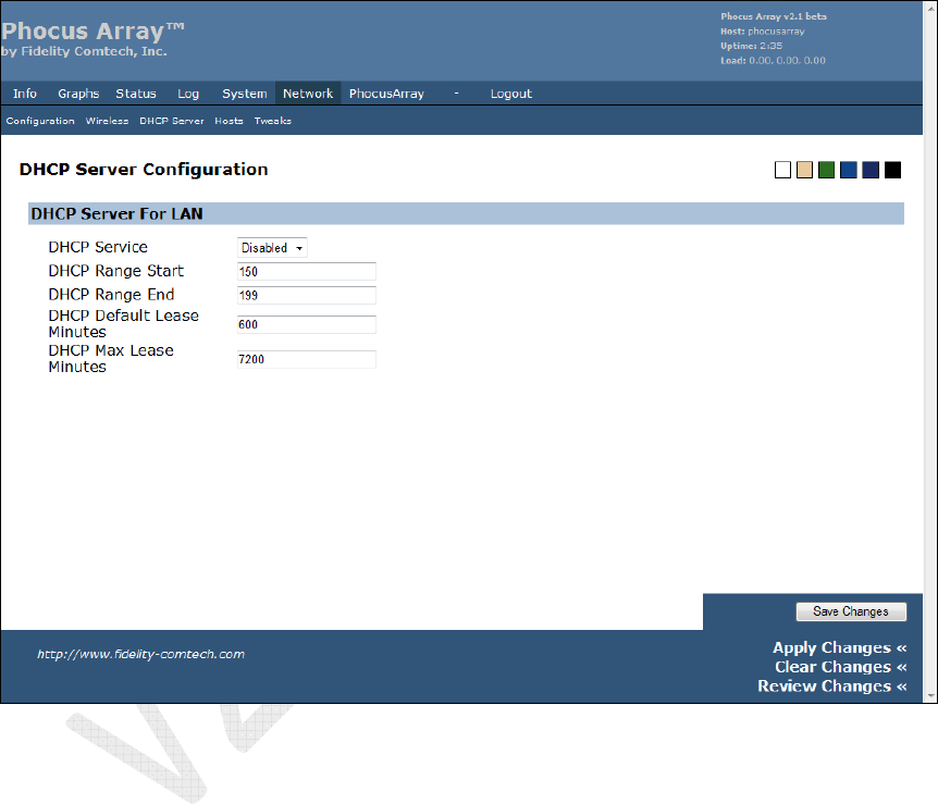
5.7.3 DHCP Server
The DHCP Server is enabled and disabled from this page. When enabled, it hands out
IP addresses using the parameters from this page.
The DHCP server serves:
• The wireless interface when the system configuration is AP Router or AP
Bridge.
• The wired interface when the system configuration is Client Router.
Figure 48 – DHCP Server Configuration
Phocus Array System Manual v2.1
69
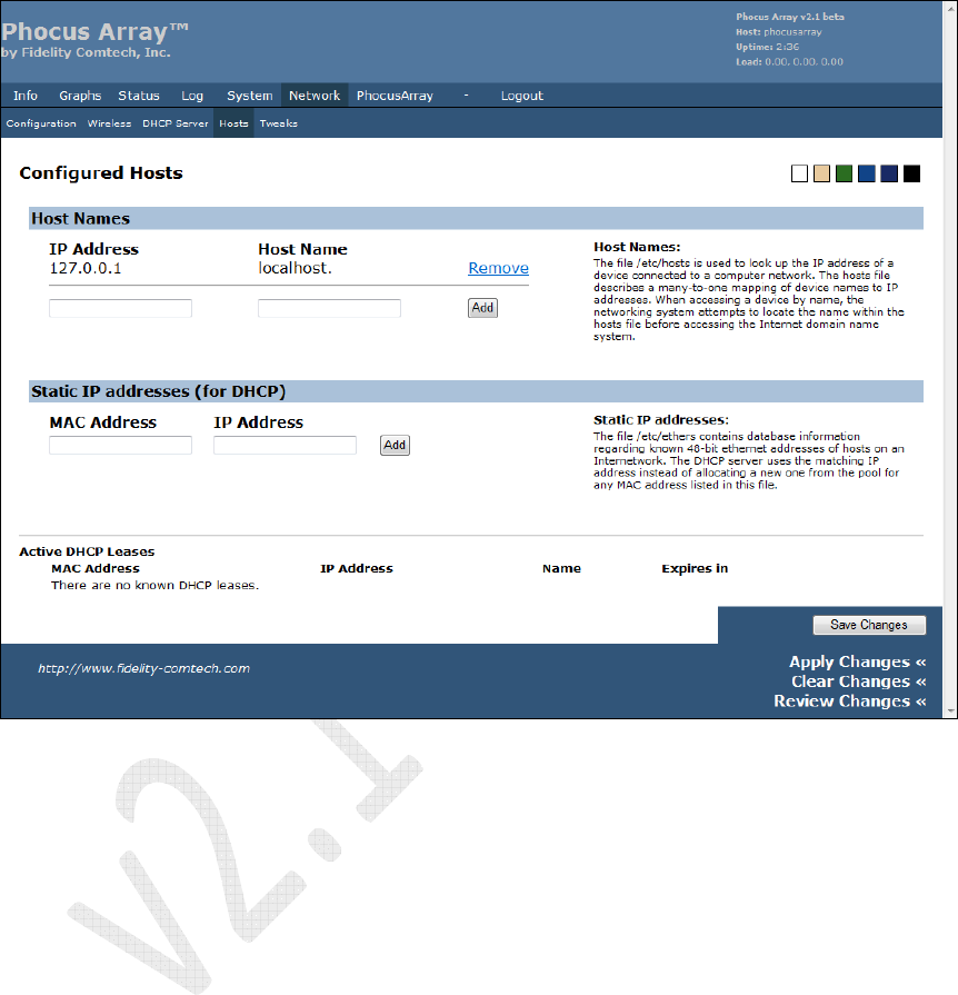
5.7.4 Hosts
Use this screen to enter the IP Address and Host Name, and Static IP addresses
(for DHCP) during system setup. See Section 4.1 Performing Initial Configuration.
Figure 49 – Host Configuration
Phocus Array System Manual v2.1
70
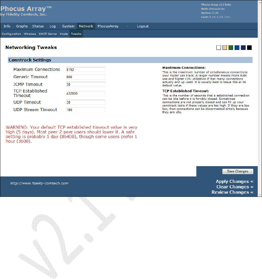
5.7.5 Tweaks
Enter networking tweaks to improve performance.
Figure 50 – Networking Tweaks
Phocus Array System Manual v2.1
71
5.8 PhocusArray Tab
The PhocusArray menu contains the following tabs:
• Configure Antenna – set beamsteering mode, set sweep interval
• Monitor Stations – monitor associated client stations and their direction
• Manage Stations – assign nicknames to associated client stations
• Upload Patterns – upload antenna pattern files, view loaded patterns
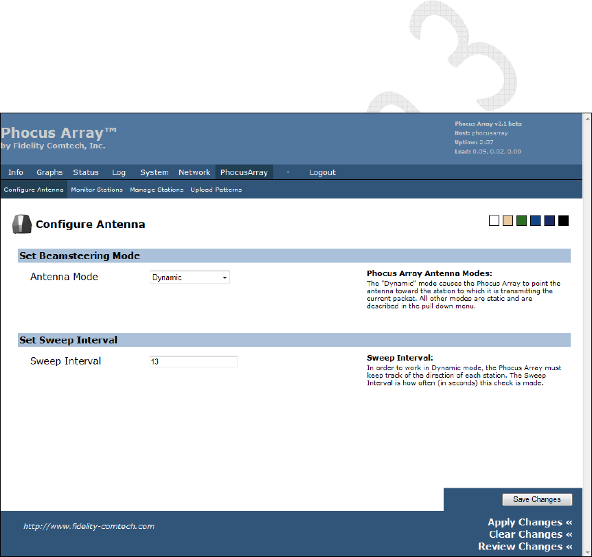
5.8.1 Configure Antenna
Use this screen to configure an antenna’s Beamsteering Mode and Sweep Interval.
• Set Beamsteering Mode is used to enable either a static antenna pattern
(e.g. Omnidirectional, Co-Phase 0 deg, etc.) or a Dynamic mode.
• Set Sweep Interval is used to set the number of seconds between sweeps.
Figure 51 – Configure Antenna
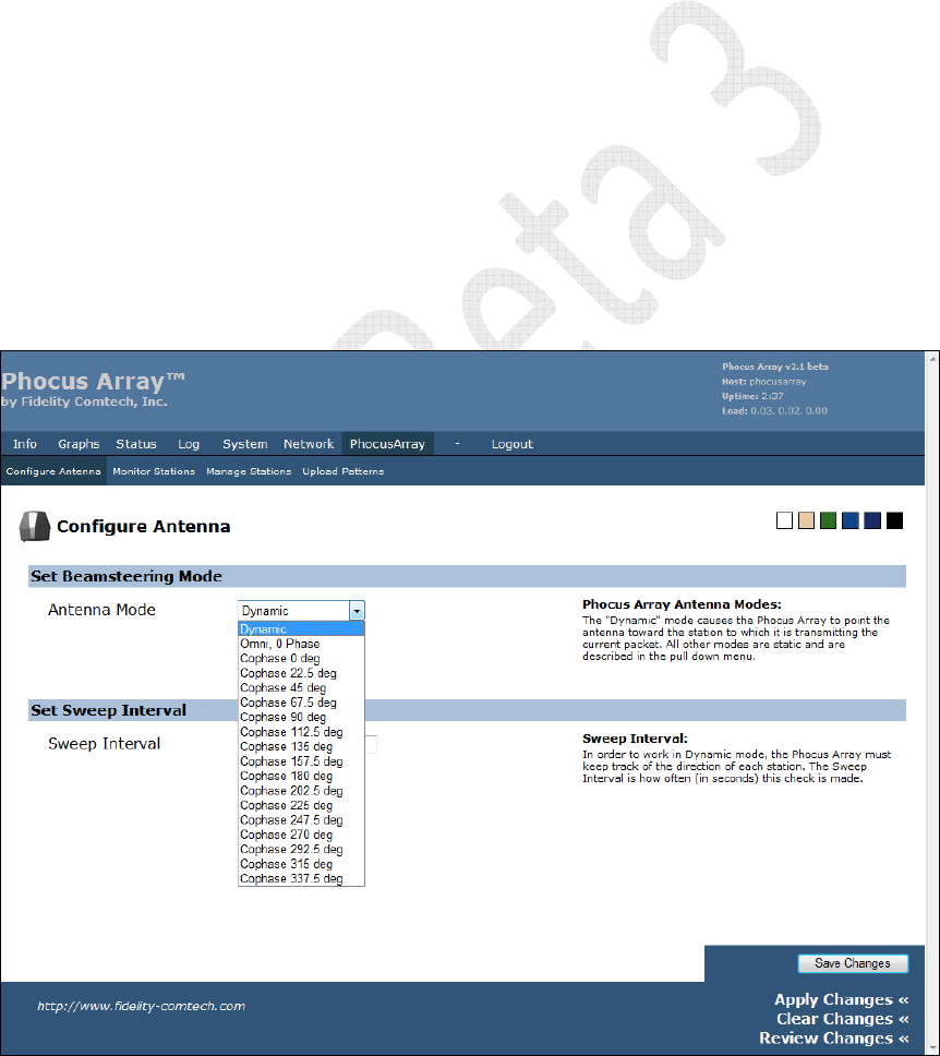
Set Beamsteering Mode
Select the antenna system configuration with the Set Beamsteering Mode control:
• A static state selection such as Co-Phase 0 deg configures the antenna to a
particular pattern and leaves it that way until administered differently. Both
transmitted and received radio communications use the designated pattern.
Phocus Array System Manual v2.1
72
• Dynamic mode allows the Phocus Array System to determine approximately
where the client radios are located, and sends any transmissions to a client
radio using one of the system patterns for that client (receives are done with an
omni-directional pattern).
Defining custom patterns may improve your performance depending on your
application. See Section 2.5 for more on custom patterns.
Static States Selections
A user can select a static state, and thereby disable scanning of client radios and fix the
antenna in a predetermined pattern or azimuth.
• Omnidirectional is 0 Phase which is preset to the Omnidirectional pattern for
the factory configured patterns. All communications (transmit and receive) are
performed with this Omnidirectional pattern
• Co-Phase 0 deg to Co-Phase 337.5 deg creates an antenna pattern that
optimizes transmissions and receives in one direction. “0” degrees is indicated
on the Phocus Array System by the orientation tab that is stamped on the
bottom of the housing (see Figure 10). If you look down on the antenna from
above as if it were a clock face, 90 degrees is at 9 o’clock, 180 degrees is at 6
o’clock and 270 degrees is at 3 o’clock.
You must click the Save Changes button and then click Apply Changes for the new
antenna pattern to take effect. This setting will take effect immediately and remain
effective even through system power cycles.
Figure 52 – Set Beamsteering Mode

Phocus Array System Manual v2.1
73
Generally you’ll get the best reception using the Phocus Array System in the following
modes (best first) and adhering to the installations recommendations in Section 3.1.3.
• Custom Pattern (designed for your application).
• Co-Phase 0 deg to Co-Phase 337.5 deg Patterns – The factory pre-defined
patternsCo-Phase have high efficiency, generate less interference, provide
better spectral reuse, and afford more privacy than a omni pattern.
• Dynamic Mode
o In Dynamic mode, the Phocus Array System periodically “sweeps”
(every Sweep Interval) using all stored directional beam patterns
(States) to determine which pattern results in the best signal from the
particular client’s radio. All signal values are stored, and the best signal
value determines the beam pattern that will be used for transmitting
data to that specific station.
o If Dynamic mode is selected, you should select the Sweep Interval.
Essentially, the Sweep Interval tells the Phocus Array System how
often to stop and recompute the directional optimization for each
associated wireless client. The Sweep Interval can be set to anywhere
from 5 to 300 seconds.
• Default Pattern (Omnidirectional mode).
Consult with Fidelity Comtech if you have special requirements for scanning.
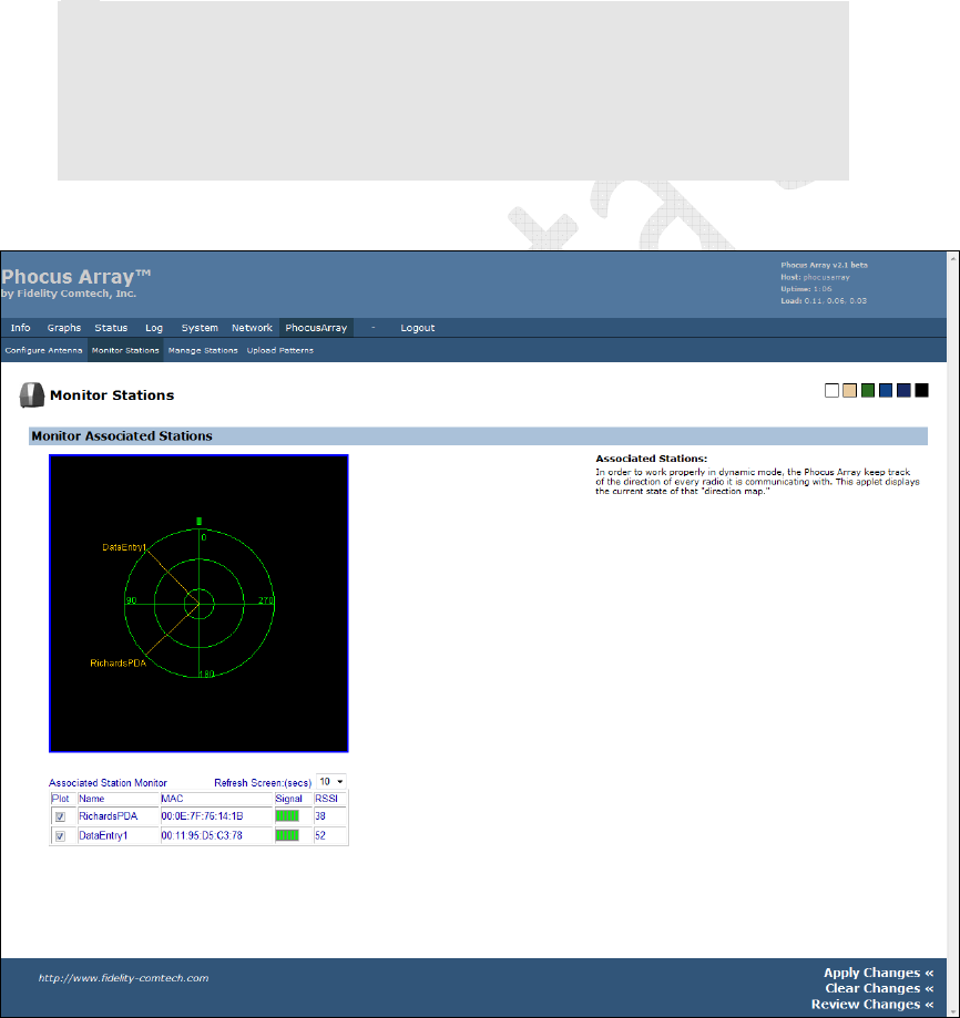
5.8.2 Monitor Stations
When in Dynamic mode the Phocus Array System periodically scans through all
antenna patterns (except the Default state) searching for the strongest RSSI value of
associated client stations and determines their approximate direction (or more
precisely the “angle of arrival” of its packets). Utilizing Phocus Array – Monitor
Stations, you can view the results of the most recent antenna system scan in Dynamic
mode.
After clicking the Monitor Stations button, you may be asked to accept and download
a Java component from the Phocus Array System. This Fidelity Comtech authored
component is a graphic that allows you to “see” a radar-like display of the direction of
802.11-associated clients. Click Yes to accept the download of the component.
See Figure 53 for an example of the screen, in this case, illustrating two client stations
associated with the system. By clicking the Plot checkbox in the first column, the
radar display will draw a line illustrating the “angle of arrival” (i.e. the approximate
direction) of the station with relationship to the Phocus Array System.
Note: Tthe green orientation mark at 0 degrees at the top of the radar display – it
represents the orientation mark on the Phocus Array System base, as if you are
looking down on the top of the system.
The Refresh Screen control sets the rate at which the browser asks the Phocus Array
System for data to display, and thus updates the radar display. (This is different than
Phocus Array System Manual v2.1
74
the Sweep Interval described on the Antenna Configuration screen, which is how
often the antenna system scans the for station position.) Ideally the Refresh Screen
setting should be the same or larger than the Sweep Interval.
If a station is moving (e.g. a laptop PC or handheld pocket computer) the radar display
will up automatically update changes in apparent direction of the client. Note, even if
a client station is stationary, the display may occasionally show different directions for
the client. This is normal and reflects the changing conditions of the RF environment,
including reflections, obstructions, and possibly movement of other objects in the
environment or the fact that a client may be aligned between two antenna states.
Note
: Display of direction and RSSI values only is relevant to
Dynamic
mode. Even
though Station
MAC
addresses are listed in the
Associated Station Monitor
table when
Static
mode is selected; the radar plot produced is only relevant to the
Dynamic
mode scans.
Note
: If a new station associates, its MAC will automatically appear in the
Associated
Station Monitor
table.
Figure 53 – Monitor Associated Stations
If you download new antenna patterns with a greater or less number of states, the
display will adapt to however many states are loaded in the Phocus Array System.

Phocus Array System Manual v2.1
75
If a new client station associates with the Phocus Array System, its MAC will
automatically appear in the Associated Station Monitor table with a name of
unnamed. The Phocus Array System then attempts to scan the new client station and
if successful, a direction will be established it. To display the direction, click the Plot
checkbox adjacent to the MAC. If the client station cannot be successfully scanned, its
MAC address still appears in the Associated Station Monitor table, but with a 0
RSSI value.
Note
: With the antenna in
DYNAMIC
mode an associated client station with an
incomplete/indeterminate scan will appear as a MAC address or name in the
center of the radar display.
Note
: With the antenna in
STATIC
mode an associated client station MAC/name will
appear in the center of the radar display.
An incomplete Dynamic mode scan can be the result of a client station being turned
off or moving out of range or aggressive radio power management by the client.
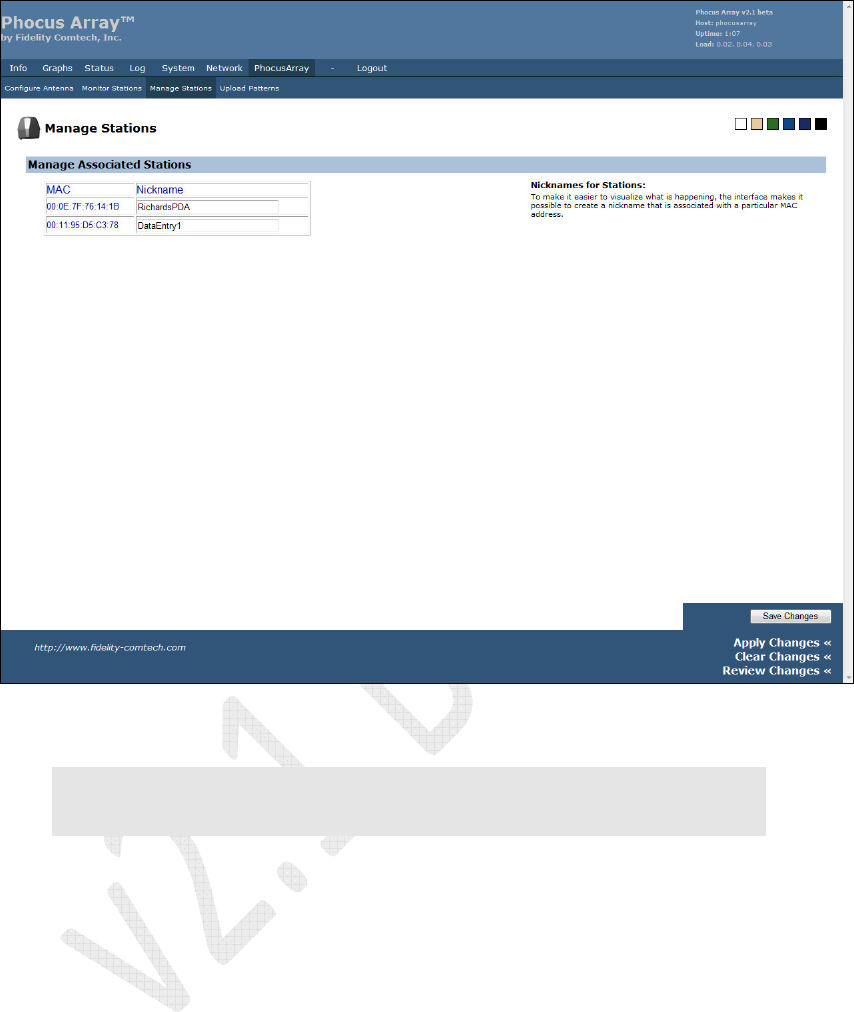
5.8.3 Manage Stations
By utilizing the Manage Stations screen in the PhocusArray menu, as shown below,
you can give a Nickname (name) to a client station. This name is local to the Phocus
Array System and is not related to 802.11 broadcast nickname.
Until a client station is given a name using this screen, the Associated Station
Monitor described in Section 5.8.2 only displays MAC addresses in the radar plot.
Naming stations allows you to assign meaningful names to clients in your network. It
also makes it easy to see when a new (perhaps unwelcome) station arrives in the
network.
To assign a name, type a character string into the text box to the right of MAC
address. It can be anything you feel descriptive of the client such as “Ricks Laptop” or
“Node in Room 6”. After entering the desired names, click the Apply button to have
the Phocus Array System memorize the MAC/Name pair. This name will remain in
the system associated with the MAC through power cycles, and even if the client
station becomes disassociated. The next time station associates, the system will
automatically display the name on this screen as well as the PhocusArray – Monitor
Stations screen.
Phocus Array System Manual v2.1
76
Figure 54 – Manage Associated Stations
Note: After clicking the
Apply
button, the names will be stored, but the screen may not
refresh correctly on this screen. Click your browser’s
Refresh
button to see the
newly assigned names.
Phocus Array System Manual v2.1
77
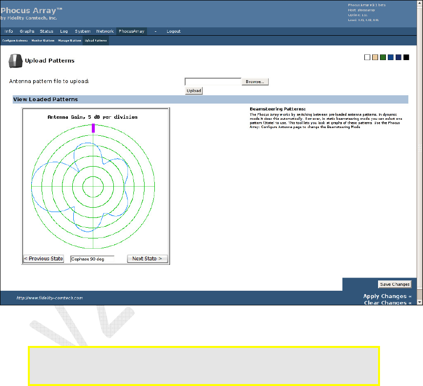
5.8.4 Upload Patterns
Use this screen to upload custom antenna pattern files, and to view pre-loaded
patterns. Fidelity Comtech can design antenna patterns for your facility upon request.
You can review a graphic of each of the currently loaded patterns in the Phocus Array
System by clicking the Next State or Previous State buttons. Clicking these buttons
does not change the state or operation of the system. Keep in mind the orientation
mark illustrated in these graphics and their relationship to the actual orientation of the
mark on the Phocus Array System case. Dynamic mode is not illustrated in this pane.
Figure 55 – View Loaded Patterns
Caution: Uploading a new set of patterns permanently overwrites the factory default
patterns. Contact Fidelity Comtech for custom patterns such as those
described in Section 2.3.
To upload a new patterns file:
1. Click the Browse button to navigate to the location of the file.
2. Select an appropriate file.
3. Click the Upload button.
4. The upload and programming of new patterns into the system takes about one
minute, after which the antenna system will be in the static “Default” state.
Phocus Array System Manual v2.1
78
5. Review the newly download patterns using the View Loaded Patterns
control.
6. Click the Configure Antenna button and use the Antenna Mode drop-down
list to select and activate a different static pattern or Dynamic mode.
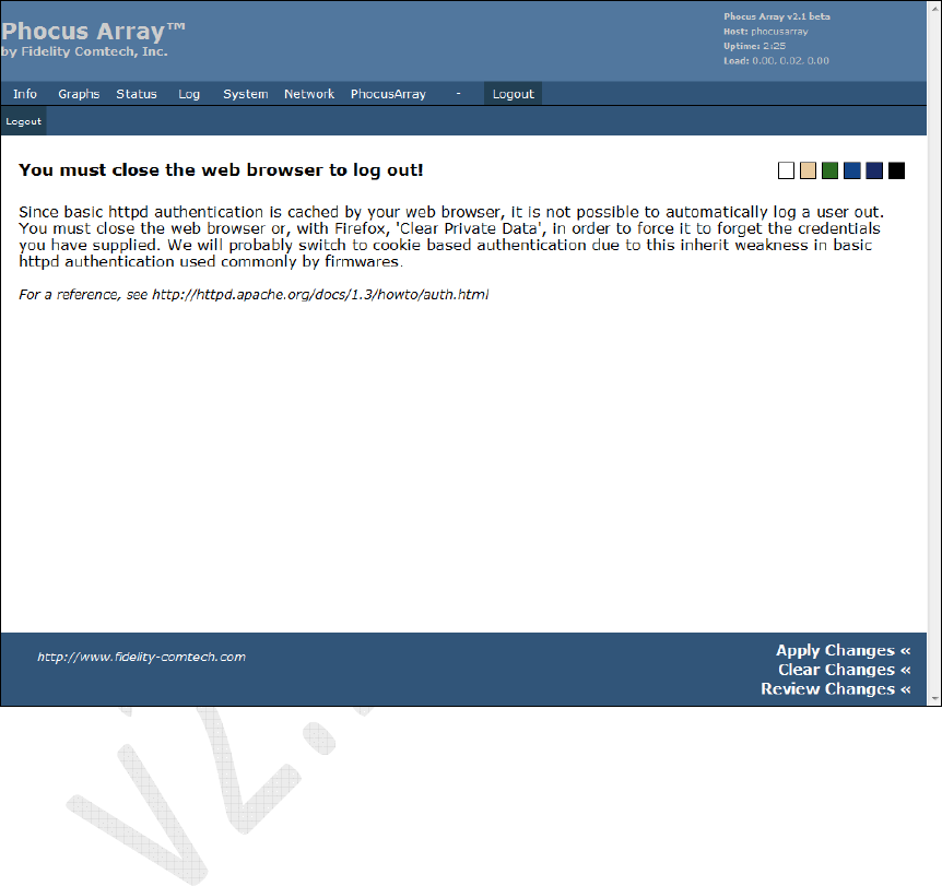
5.9 Logout Tab
Figure 56 – Logout