Fidelity Comtech FCI3100X Phased Array WLAN Terminal User Manual Phocus 2 1 Beta 3
Fidelity Comtech, Inc. Phased Array WLAN Terminal Phocus 2 1 Beta 3
Contents
- 1. User Manual Part One
- 2. User Manual Part Two
- 3. User Manual Part Three
User Manual Part Two
Phocus Array System Manual v2.1
35
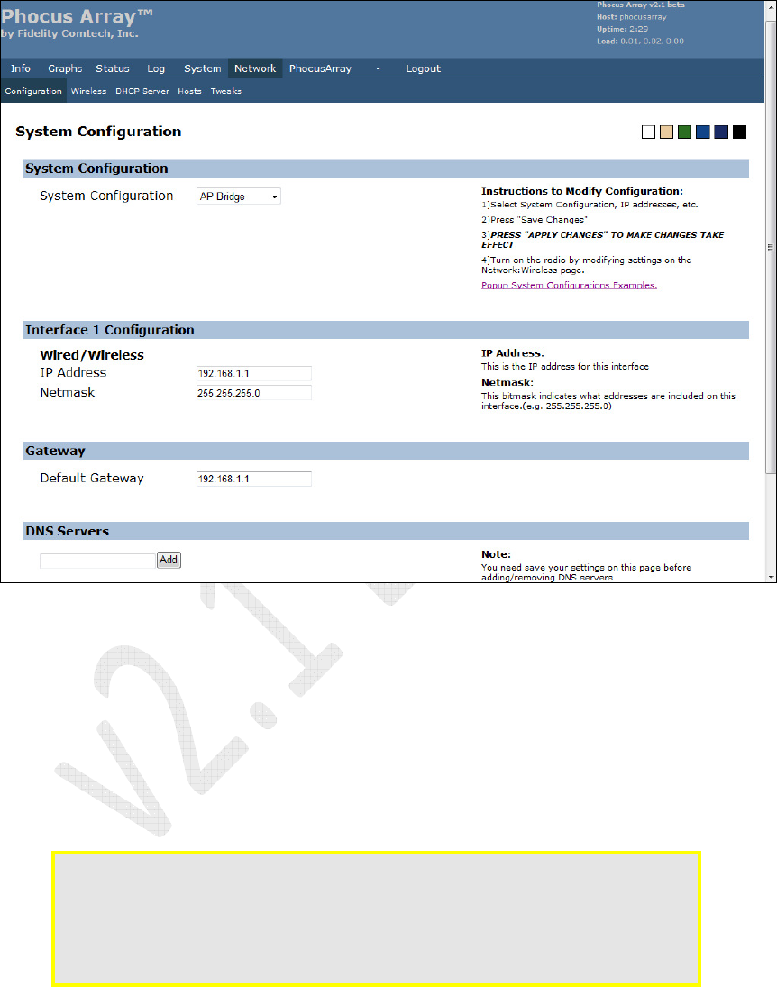
4.2.5 System Configuration Options
1. Click the Network tab. The System Configuration screen displays.
Figure 17 – System Configuration
Use the System Configuration drop-down list to select the basic operating mode for
the system. The number of interfaces to administer (wired/wireless) and the sequence
in which they are listed changes according to which system configuration you select.
Selecting AP Bridge, as shown above, results in only a single wired/wireless
interface, whereas selecting AP Router results in two interfaces, one wired and one
wireless.
Caution: The sequence of types of interfaces displayed changes when you select a
different
System Configuration
. Please re-verify that the
IP Address
, etc.
is correct for each wired and wireless interface before saving and applying
changes. If you apply changes to the system with incorrect IP addresses,
this can render the Phocus Array system inoperable and require extensive
work to recover the system.
Phocus Array System Manual v2.1
36
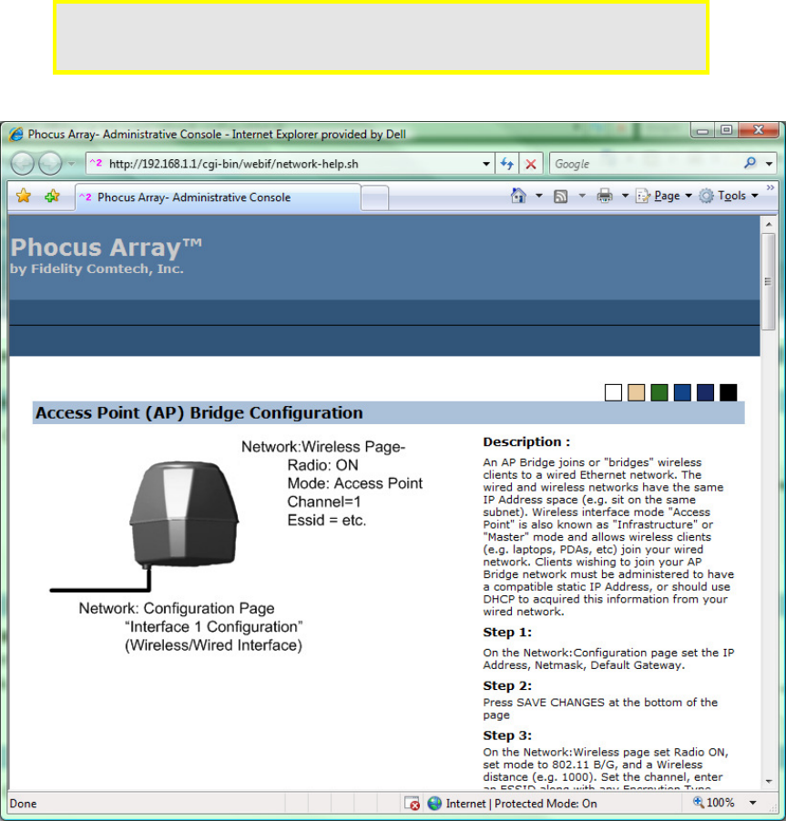
2. Enter the correct IP Addresses in the Wireless Interface and Wired Interface
fields. Click the Popup System Configurations Examples link under the
System Configuration section for detailed descriptions of the configuration
options.
Caution: The relative positions of the
Wireless
and
Wired
interfaces change when
the
System
Configuration
is changed from
AP
Router
or
Ad Hoc Router
to
Client
Router
. Always check the IP Address and other settings.
Figure 18 – System Configurations Examples
Phocus Array System Manual v2.1
37
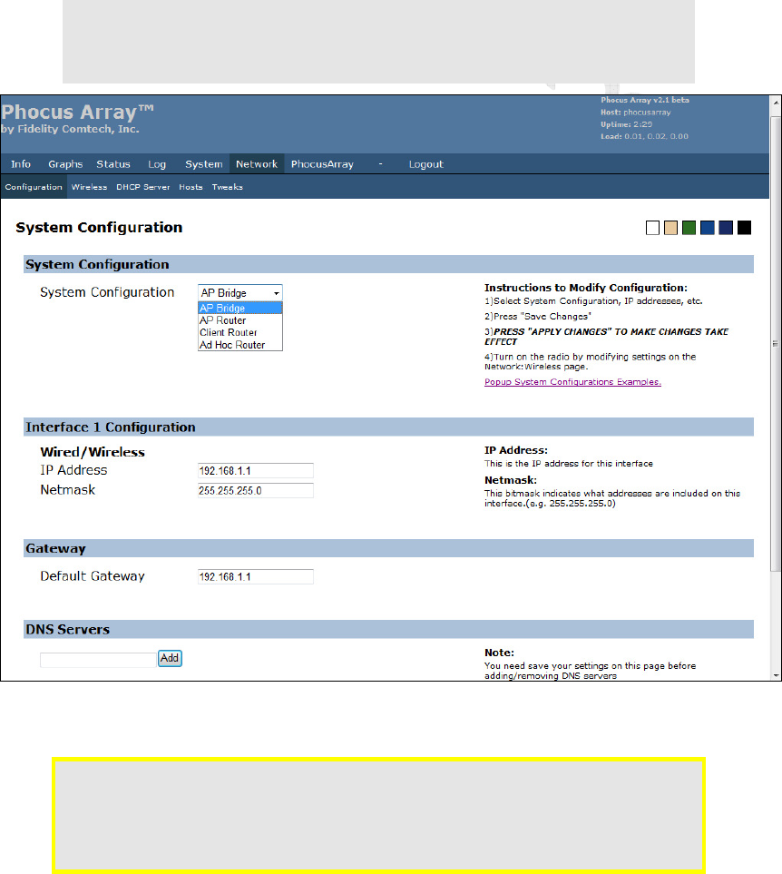
3. Select the desired configuration from the System Configuration drop-down
list.
AP Bridge has only one interface to configure.
a. Under Interface 1 Configuration, you can see fields for the IP Address
and Netmask of the interface. These may be configured if desired.
b. Click the Save Changes button.
c. Click Apply Changes.
Note: When these changes are applied to the wired network, the IP address of the
Phocus Array System will change, requiring reconfiguration of your
administration computer or network to continue communicating with the
Phocus Array System.
Figure 19 – System Configuration Options
Caution: Optional
DNS Servers
settings should be saved after saving changes for
System Configuration
and
Interfaces
. If you accidentally added DNS
servers out of order, simply click the
Remove
button to eliminate DNS
servers. You may then administer the interfaces, save changes, and add
DNS servers.
Phocus Array System Manual v2.1
38
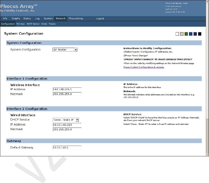
AP Router
a. Under Interface 1 Configuration, enter the IP Address for the Wireless
Interface.
b. Under Interface 2 Configuration, enter the IP Address for the Wired
Interface.
c. Click the Save Changes button.
d. Click Apply Changes.
Figure 20 – AP Router Configuration
Phocus Array System Manual v2.1
39
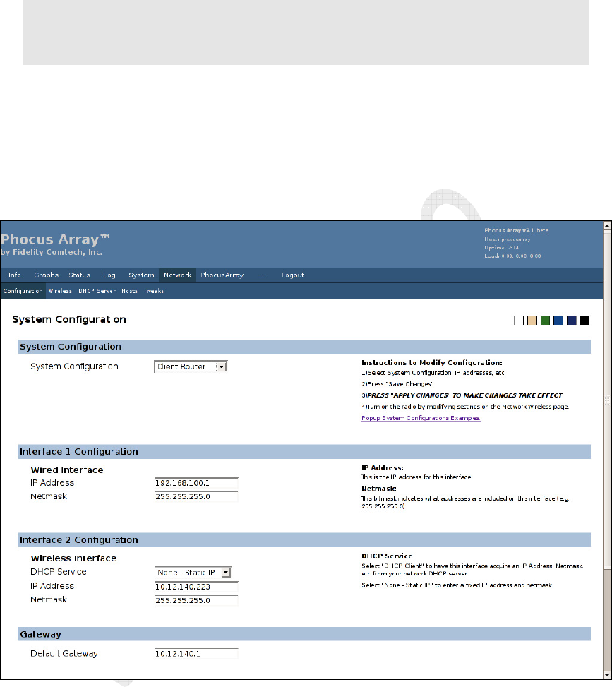
Client Router
Note
: The relative positions of the
Wireless
and
Wired
interfaces change when the
System
Configuration
is changed from
AP Router
or
Ad Hoc Router
to
Client Router
. Always
check the
IP Address
and other settings. Enter the correct
IP Addresses
in the
Wireless
Interface
and
Wired Interface
fields.
a. Under Interface 1 Configuration, enter the IP Address for the Wired
Interface.
b. Under Interface 2 Configuration, enter the IP Address for the Wireless
Interface.
c. Click the Save Changes button.
d. Click Apply Changes.
Figure 21 – Client Router Configuration

Phocus Array System Manual v2.1
40
Ad Hoc Router
Note
: The relative positions of the
Wireless
and
Wired
interfaces
change
when
the
System
Configuration
is changed
from
Client Router
to
Ad Hoc Router
or
AP Router
. Always
check the
IP Address
and other settings. Enter the correct
IP addresses
in the
Wireless
Interface
and
Wired Interface
fields.
a. Under Interface 1 Configuration, enter the IP Address for the Wireless
Interface.
b. Under Interface 2 Configuration, enter the IP Address for the Wired
Interface.
c. Click the Save Changes button.
d. Click Apply Changes.
Figure 22 – Ad Hoc Router Configuration
Phocus Array System Manual v2.1
41
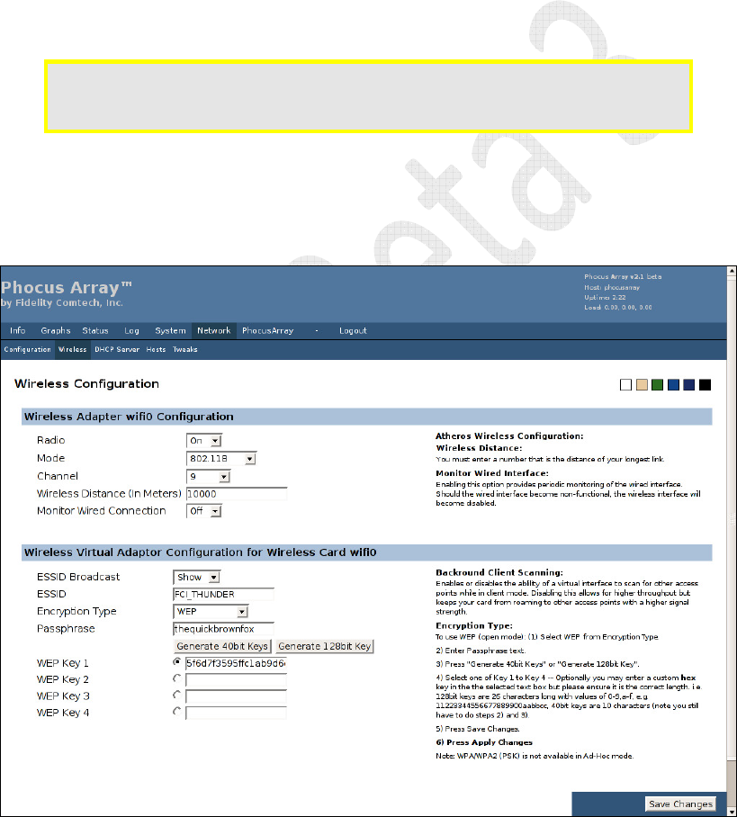
4.2.6 Wireless Adapter Configuration
1. Click Wireless in the Network menu bar.
2. Enter the Wireless Adapter configuration.
3. Enter the ESSID configuration.
4. Select the Encryption Type from the drop-down list.
5. Enter the Passphrase (for WEP).
6. Enter the WEP Key or WEP PSK in the appropriate field.
7. Click the Save Changes button.
8. Click Apply Changes.
Caution: Modification of the
Encryption Type
requires the Phocus Array System to
be rebooted. After saving and applying changes, you must reboot the
system for the new encryption settings to take effect.
9. Click Reboot in the System menu bar.
10. Click Yes, really reboot now. The system will be taken out of service for
about two minutes when rebooted. It boots to the last saved/applied
configuration.
Figure 23 – Wireless Configuration – WEP
Phocus Array System Manual v2.1
42
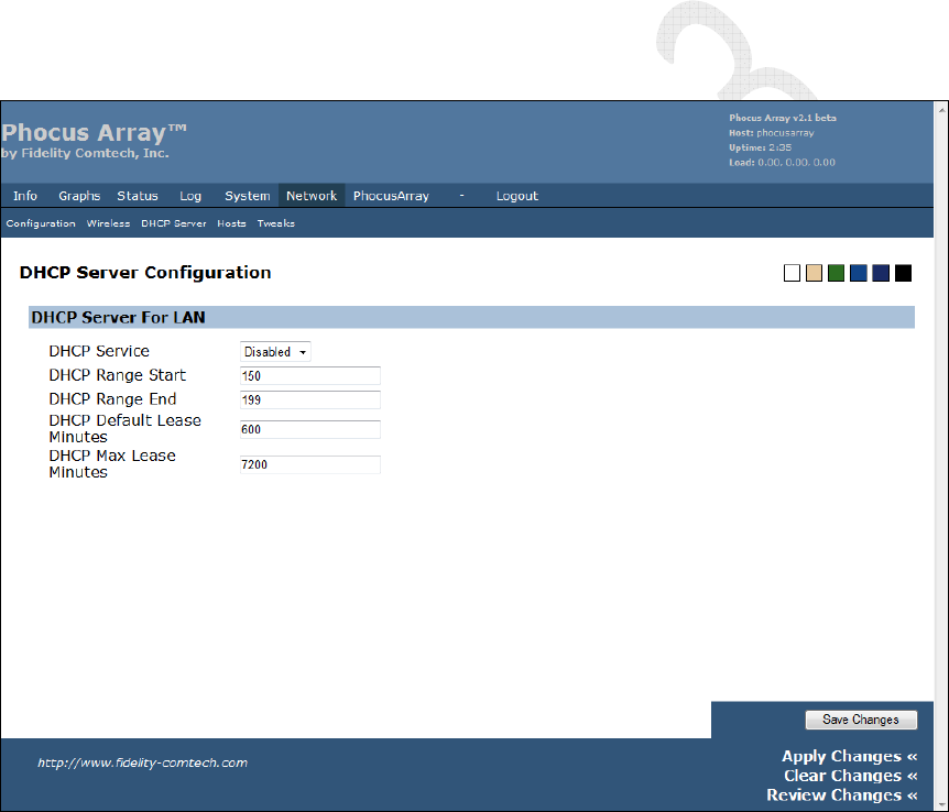
4.2.7 DHCP Server Configuration (optional)
The system can be configured to serve DHCP information (e.g. IP address) to the
LAN by enabling the DHCP server. The LAN in this case would be the Wireless
Interface for a system configuration of AP Router of Ad Hoc Router, or Wired
Interface for a system configuration of Client Router. DHCP server is not available
for the AP Bridge configuration.
1. Click DHCP Server in the Network menu bar.
2. Select Enabled from the DHCP Service drop-down list.
3. Enter the DHCP Server configuration.
4. Click the Save Changes button.
5. Click Apply Changes.
Figure 24 – DHCP Server Configuration
Phocus Array System Manual v2.1
43
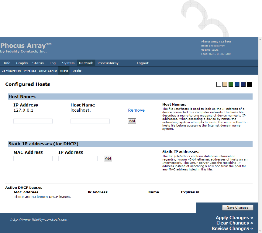
4.2.8 Adding Hosts (optional)
1. Click Hosts in the Network menu bar.
2. To add a device to the network, enter the IP Address and the Host Name.
3. Click the Add button.
4. Click the Save Changes button.
5. Click Apply Changes.
6. To add Static IP Addresses (for DHCP), enter the device’s MAC Address
and IP Address.
7. Click the Add button.
8. Click the Save Changes button.
9. Click Apply Changes.
Figure 25 – Adding Hosts
Phocus Array System Manual v2.1
44
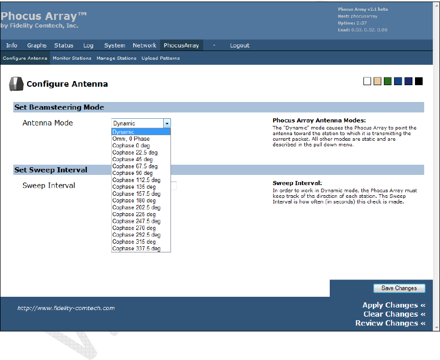
4.2.9 Antenna Configuration
1. Use the PhocusArray screens to configure the behavior of the antenna and to
monitor the stations associated with the unit.
2. Click the PhocusArray tab. The Configure Antenna screen displays.
3. Select the desired Antenna Mode from the drop-down list.
4. Set the Sweep Interval, if desired.
5. Click the Save Changes button.
6. Click Apply Changes.
Figure 26 – Configure Antenna
Once the above steps have been completed, a wireless client should be able to find and
associate the Phocus Array System in AP mode.
Phocus Array System Manual v2.1
45
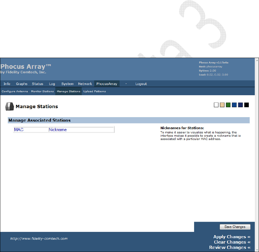
4.2.10 Manage Stations (optional)
To help monitor associations with Phocus Array System, associated stations can be
named using the Manage Station page. While a client is associated with the system, it
can be assigned a name that will be displayed on the Monitor Stations page. If the
station disassociates the name will be retained internally in the system and will
automatically reappear if the same wireless MAC Address again associates with the
system
This is a useful security feature because new, possibly unauthorized, stations will
appear as a MAC Address (without a name). A system administrator would easily
recognize “unnamed” associated stations as potential security risk.
1. Click Manage Stations in the PhocusArray menu.
2. Enter the MAC address and a Nickname for each Phocus Array station.
3. Click the Save Changes button.
4. Click Apply Changes.
Figure 27 – Manage Stations

Phocus Array System Manual v2.1
46
5 Using the Administrative Console
This section discusses the Administrative Console for the Phocus Array System. For a
quick start guide to simply getting a Phocus Array System up and running on a
network, refer to Section 4, Configuration and Software Setup.
Most common tasks can be performed using the Administrative Console for the
Phocus Array System, making it the preferred method to access the system. Common
tasks include:
• Installation and setup of the wireless and network parameters
• Monitoring client associations
5.1 Using the Administrative Console
To access the console, perform steps 1 through 4 in Section 4.2 (pages 30 through 27).
There are seven different categories of settings, each accessible from a tab at the top of
the page. Most categories have several menu options, accessible from the menu bar
just below the tabs. These options are discussed in the following sections.
• Info – System, About
• Graphs – CPU, Traffic IO, Traffic eth0, Traffic eth1, Traffic br-lan,
Traffic wifi0
• Status – System, Processes, Interfaces, DCHP Clients, Netstat, Iptables
• Log – Syslog Settings, Syslog, Kernel
• System – Settings, Password, Backup and Restore, Upgrade, Reboot
• Network – Configuration, Wireless, DHCP Server, Hosts, Tweaks
• PhocusArray – Configure Antenna, Monitor Stations, Manage Stations,
Upload Patterns
• Logout
Phocus Array System Manual v2.1
47
5.2 Info Tab
The Info menu contains the following tabs:
• System – system information
• About – information about Release 2.1
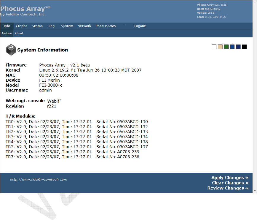
5.2.1 System
The screen displays complete system information on hardware and software.
Figure 28 – Info > System: System Information
Phocus Array System Manual v2.1
48
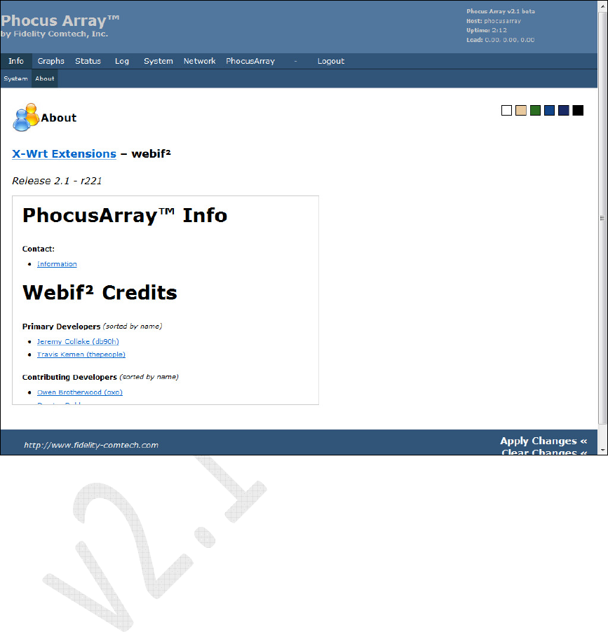
5.2.2 About
The screen displays a continuous scrolling list of information about Release 2.1,
including Contact information and Webif2 Credits.
Figure 29 – Info > About
Phocus Array System Manual v2.1
49
5.3 Graphs Tab
The Graphs menu contains the following tabs:
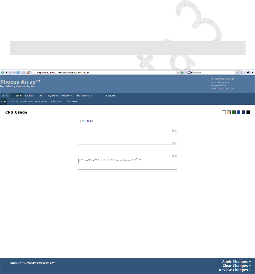
• CPU –shows CPU utilization
• Traffic Io – shows traffic on the local loopback interface and can be
ignored.
• Traffic eth0 – shows traffic on the wired interface.
• Traffic eth1 – should be ignored.
• Traffic br-lan – if configured as an AP bridge, shows traffic passing
through the bridge..
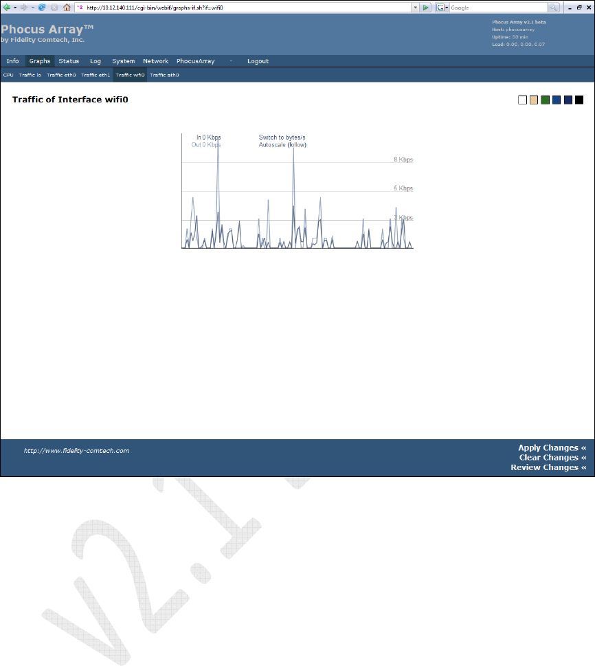
• Traffic wifi0 – shows wireless interface traffic.
• Traffic ath0 – shows same graph as wifi0.
Note
: These graphs require SVG capability from your browser. To display the graphs you must
use a browser that supports SVG, such as Mozilla Firefox 2.0.
5.3.1 CPU Usage
Figure 30 – Graphs > CPU
Phocus Array System Manual v2.1
50
5.3.2 Traffic wifi0
Figure 31 – Traffic wifi0

Phocus Array System Manual v2.1
51
5.4 Status Tab
The Status menu contains the following tabs:
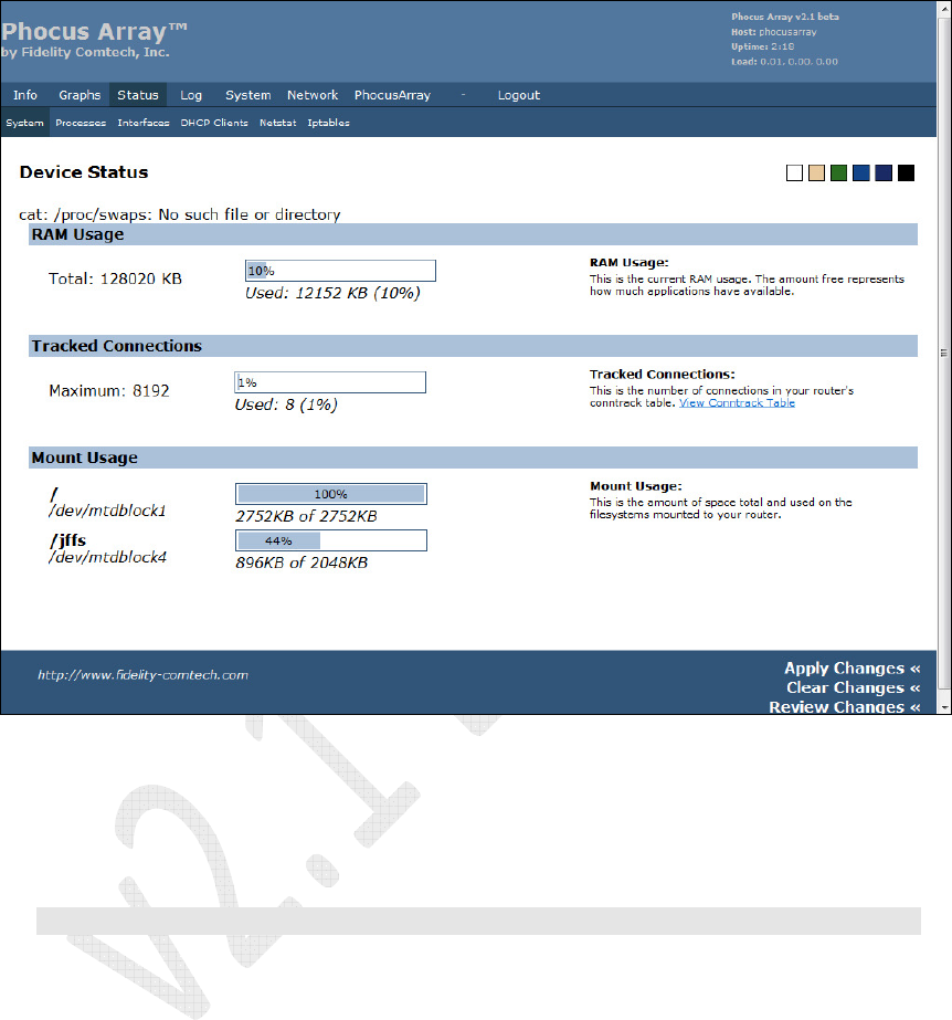
• System – device status: RAM usage, tracked connections, mount usage
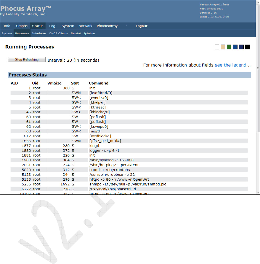
• Processes – all running processes
• Interfaces – LAN and WLAN interface data
• DHCP Clients – DHCP leases and related information
• Netstat – Ethernet/wireless physical connections, routing table, router
listening ports, connections to the router
• Iptables – Iptables status for IP packet handling rules tables
Phocus Array System Manual v2.1
52
5.4.1 System
The screen displays RAM Usage, Tracked Connections, and Mount Usage.
Figure 32 – Device Status
You can click the View Conntrack Table link to show the connections being utilized
on your system. It allows you to roughly follow the packets UDP/TCP transactions
over time.
Note: At this time this page is untested and may not work.
Phocus Array System Manual v2.1
53
5.4.2 Processes
The screen displays all processes that are running.
Click the see the legend link for more information about the fields.
Figure 33 – Running Processes
Phocus Array System Manual v2.1
54
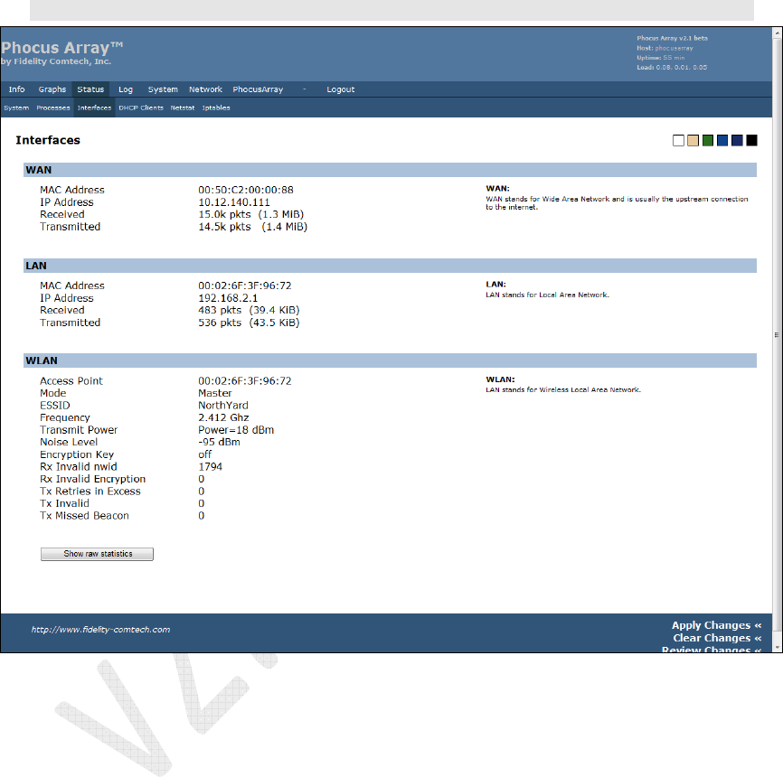
5.4.3 Interfaces
The screen displays LAN and WLAN interface data. Click the Show raw statistics
button to view the low-level interface status and configuration, which can be helpful
when calling Technical Support
Note
: The
WAN
and
LAN
designations change according to the
System Configuration.
Figure 34 – Interfaces