Fidelity Comtech FCI3100X Phased Array WLAN Terminal User Manual Phocus 2 1 Beta 3
Fidelity Comtech, Inc. Phased Array WLAN Terminal Phocus 2 1 Beta 3
Contents
- 1. User Manual Part One
- 2. User Manual Part Two
- 3. User Manual Part Three
User Manual Part One

Phocus Array
™
System
Manual
Part Number FCI-3000-UM
Document Version/Revision 2.1.A
Phocus Array System Manual v2.1
2
NOTICE
Information in this manual is subject to change without notice and does not represent a
commitment on the part of Fidelity Comtech, Inc. Portions of the software described
in this document are copyrighted by Fidelity Comtech, Inc and may not be copied or
reproduced without written consent of Fidelity Comtech, Inc. No part of this manual
may be reproduced or transmitted in any form or by any means, electronic or
mechanical, including photocopying and recording, for any purpose without the
express written permission of Fidelity Comtech, Inc.
Copyright 2007 Fidelity Comtech, Inc.
All rights reserved. Reproduction, adaptation, or translation without prior written
permission is prohibited, except as allowed under the copyright laws.
Phocus Array, G.R.I.P.S., Flexible Vector Modular Technology, FlexVMT, Geo-I,
Geo-II, and Geo-III are trademarks of Fidelity Comtech, Inc.
All other brand and product names mentioned in this document are trademarks and/or
registered trademarks of their respective holders.
This symbol indicates that this device provides a certain level of protection against
electric shock.
This symbol indicates that the user must read and understand all instructions and
warnings prior to use.
This symbol indicates that the associated jack is for a Universal Serial Bus
connection.
Fidelity Comtech, Inc
2400 Trade Centre Ave.
Longmont, Colorado, 80503, USA
General Information and Support: 303.678.8876
Fax 303.362.7545
Email: info@fidelity-comtech.com
Phocus Array System Manual v2.1
3
ABOUT THIS MANUAL
The instructions in the following chapters assume the user is adequately familiar with
the intended use and application of this device.
Knowledge of the IEEE 802.11 wireless standard as well as RF concepts, protocols,
and networking (e.g. TCP/IP and IEEE 802.3) are especially useful.
Documentation Conventions
The following format conventions are used in this document to identify special
information:
Warning statements identify conditions or practices that could result in personal
injury.
Caution statements identify conditions or practices that could result in damage to
equipment or loss of data.
Notes:
The displayed data in this document are for example purposes only.
The graphical illustrations in this document are for example purposes only and the
hardware illustrated may differ from your hardware.

Phocus Array System Manual v2.1
4
IMPORTANT SAFETY INFORMATION
Warning: Installation of this product near power lines is dangerous! For your safety,
follow the installation directions.
How to Install your Phocus Array System Safely
The following installation precautions and guidelines are extracted from the
Recommendations of the U.S. Consumer Product Safety Commission on installing
antennas.
These safety recommendations apply to all antennas.
Each year, hundreds of people are killed, mutilated, or receive severe and permanent
injuries when attempting to install an antenna. In many of these cases, the victim was
aware of the danger of electrocution, but did not take adequate steps to avoid the
hazard.
For your safety, and to help you achieve a good installation, please read and follow the
safety precautions below. They may save your life!
That this is not complete list of instructions, precautions, and installation guidelines
necessary to safely and effectively install the antenna. You should consult a
professional, as well as observe local and national code requirements.
1. If you are installing an antenna for the first time, please, for your own safety as
well as others, seek professional assistance. The professional can explain
which mounting method to use for the size and type of antenna you are about
to install.
2. Select your installation site with safety, as well as performance, in mind.
REMEMBER: ELECTRIC POWER LINES AND PHONE LINES LOOK
ALIKE. FOR YOUR SAFETY, ASSUME THAT ANY OVERHEAD LINES
CAN KILL YOU.
3. Call your electric power company. Tell them your plans and ask them to come
take a look at your proposed installation. This is a small inconvenience,
considering YOUR LIFE IS AT STAKE.
4. Plan your installation procedure carefully and completely before you begin.
Successful raising of a mast or tower is largely a matter of coordination. Each
person should be assigned a specific task, and should know what to do and
when to do it. One person should be designated as the leader/coordinator of the
operation to call out instructions and watch for signs of trouble.
5. When installing your antenna, REMEMBER: DO NOT USE A METAL
LADDER. DO NOT WORK ON A WET OR WINDY DAY. DO DRESS
PROPERLY: shoes with rubber soles and heels, rubber gloves, long sleeved
shirt or jacket.

Phocus Array System Manual v2.1
5
6. If the assembly starts to drop, get away from it and let it fall. Remember, an
antenna, mast, cable, and metal guy wires are all excellent conductors of
electrical current. Even the slightest touch of any of these parts to a power line
completes an electrical path through the antenna and the installer – THAT’S
YOU!
7. If ANY PART of the antenna system should come in contact with a power line,
DON’T TOUCH IT OR TRY TO REMOVE IT YOURSELF. CALL YOUR
LOCAL POWER COMPANY. They will remove it safely.
If an accident should occur with the power lines, call for qualified emergency help
IMMEDIATELY.
Warnings and Precautions
Cautions: Always use the AC power adapter that accompanied the system. Using a
different AC power adapter may cause permanent damage to your system.
Always use outdoor-rated CAT5 or better Ethernet cable in order to
comply with radiation and conducted emissions and immunity.
Use included weatherproof Ethernet cable connector boot to protect
external connection integrity.
Always ensure a strain relief system is employed on the Ethernet cable to
prevent the weight of the cable from causing intermittent connections for
the cable connector.
Do not attempt to immerse the device or accessories in water or cleaning
fluid, as there are electronic components inside that will be permanently
damaged.
Maintaining Device Effectiveness
The recommended operating conditions for the device are -40° to 85° C, 0% to 100%
humidity. The recommended transport and storage conditions are -20°C to 50 °C; 0 to
95% non-condensing humidity; -1000 to 10,000 feet or 787.9-522.7 mm Hg.
Although the Phocus Array System is designed for outdoor use it should not be
immersed in water or other fluids. The housing may be wiped clean with a soft cloth
dampened with mild soapy water.

Phocus Array System Manual v2.1
6
TABLE OF CONTENTS
1 Overview ..................................................................................................... 10
1.1.1 Device Description And Specifications ............................................... 12
1.1.2 Core Features .................................................................................... 13
1.1.3 Electrical Characteristics .................................................................... 14
1.1.4 Certifications, Compliance And Warranty ........................................... 15
1.1.5 Definitions .......................................................................................... 15
2 Principles Of Geo-I (Beam Shaping And Steering) .................................. 17
2.1 Theory.................................................................................................. 17
2.2 Phased Array Technology .................................................................... 17
2.3 Benefits Of The Flexvmt (Phased Antennas In A Uniform Circular
Array Configuration) ............................................................................. 18
2.3.1 Geolocation ........................................................................................ 18
2.3.2 Reach ................................................................................................ 18
2.3.3 Interference Mitigation ........................................................................ 19
2.3.4 Privacy / Security ............................................................................... 19
2.4 The Phocus Array System Implementation .......................................... 19
2.5 Additional Beam Patterns .................................................................... 21
3 Installation And Hardware Set Up ............................................................. 23
3.1 Installation Considerations ................................................................... 25
3.1.1 Safety ................................................................................................ 25
3.1.2 How To Install Your Phocus Array System Safely .............................. 25
3.1.3 Placement And Performance ............................................................. 26
3.2 Installation Procedure .......................................................................... 26
4 Configuration And Software Setup ........................................................... 29
4.1 Configuration Sequence And Options .................................................. 29
4.2 Performing Initial Configuration ............................................................ 30
4.2.1 Connecting The Phocus Array System To Your Computer ................. 30
4.2.2 Administering The Password .............................................................. 31
4.2.3 Login .................................................................................................. 33
4.2.4 System Settings ................................................................................. 34
4.2.5 System Configuration Options ............................................................ 35
4.2.6 Wireless Adapter Configuration .......................................................... 41
4.2.7 Dhcp Server Configuration (Optional) ................................................ 42
4.2.8 Adding Hosts (Optional) ..................................................................... 43
4.2.9 Antenna Configuration ....................................................................... 44
4.2.10 Manage Stations (Optional) ................................................................ 45
5 Using The Administrative Console ........................................................... 46
5.1 Using The Administrative Console ....................................................... 46
5.2 Info Tab................................................................................................ 47
5.2.1 System ............................................................................................... 47

Phocus Array System Manual v2.1
7
5.2.2 About ................................................................................................. 48
5.3 Graphs Tab .......................................................................................... 49
5.3.1 Cpu Usage ......................................................................................... 49
5.3.2 Traffic Wifi0 ........................................................................................ 50
5.4 Status Tab ........................................................................................... 51
5.4.1 System ............................................................................................... 52
5.4.2 Processes .......................................................................................... 53
5.4.3 Interfaces ........................................................................................... 54
5.4.4 Dhcp Clients ...................................................................................... 55
5.4.5 Netstat ............................................................................................... 56
5.4.6 Iptables .............................................................................................. 57
5.5 Log Tab................................................................................................ 58
5.5.1 Syslog Settings .................................................................................. 58
5.5.2 Syslo .................................................................................................. 59
5.5.3 Kernel ................................................................................................ 60
5.6 System Tab .......................................................................................... 61
5.6.1 Settings .............................................................................................. 61
5.6.2 Password ........................................................................................... 62
5.6.3 Backup And Restore .......................................................................... 63
5.6.4 Uploading Firmware Updates Or Upgrades ........................................ 64
5.6.5 Reboot ............................................................................................... 65
5.7 Network Tab ........................................................................................ 66
5.7.1 Configuration...................................................................................... 66
5.7.2 Wireless ............................................................................................. 67
5.7.3 Dhcp Server ....................................................................................... 68
5.7.4 Hosts ................................................................................................. 69
5.7.5 Tweaks .............................................................................................. 70
5.8 Phocusarray Tab ................................................................................. 71
5.8.1 Configure Antenna ............................................................................. 71
5.8.2 Monitor Stations ................................................................................. 73
5.8.3 Manage Stations ................................................................................ 75
5.8.4 Upload Patterns ................................................................................. 77
5.9 Logout Tab ........................................................................................... 78

Phocus Array System Manual v2.1
8
TABLE OF FIGURES
Figure 1 – Phocus Array Antenna System in a Wireless Access Point Application ...................... 10
Figure 2 – Phocus Array System Block Diagram ........................................................................... 11
Figure 3 – Omnidirectional Antenna Pattern – “0 Phase” .............................................................. 20
Figure 4 – Factory Default Antenna Patterns “Co-Phase 247.5” and “Co-Phase 315” ................. 21
Figure 5 – Sector Antenna Pattern ................................................................................................ 22
Figure 6 – Two Lobe Pattern ......................................................................................................... 22
Figure 7 – Antenna in Outdoor Enclosure...................................................................................... 23
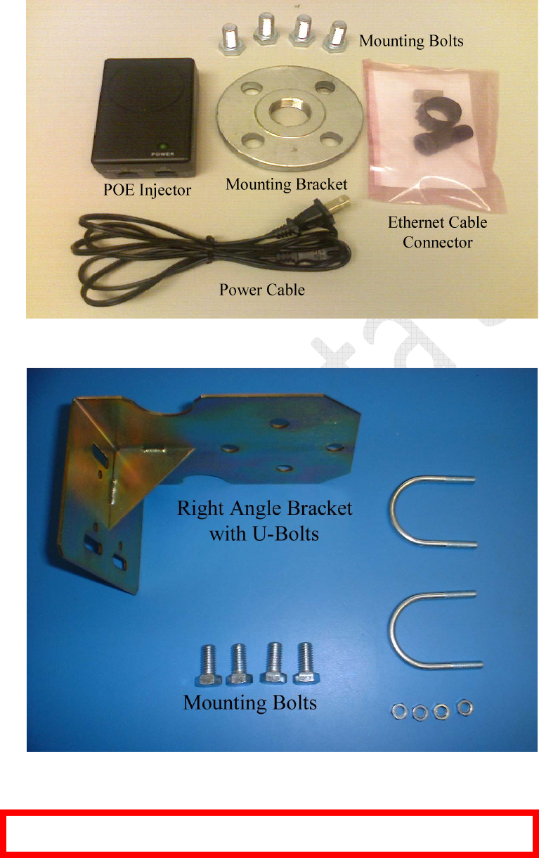
Figure 8 – Power Injector, Cable, Pole Mounting Bracket, and Accessories ................................ 24
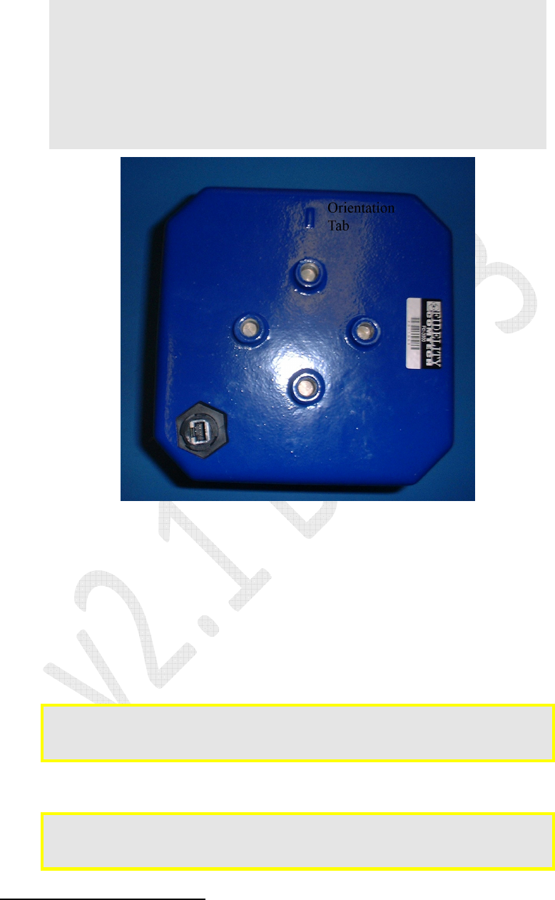
Figure 9 – Right Angle Mounting Hardware ................................................................................... 24
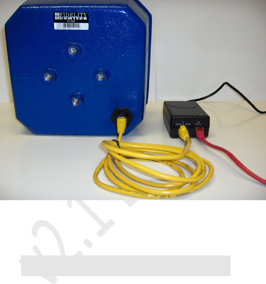
Figure 10 – Bottom View showing Orientation Tab ....................................................................... 27
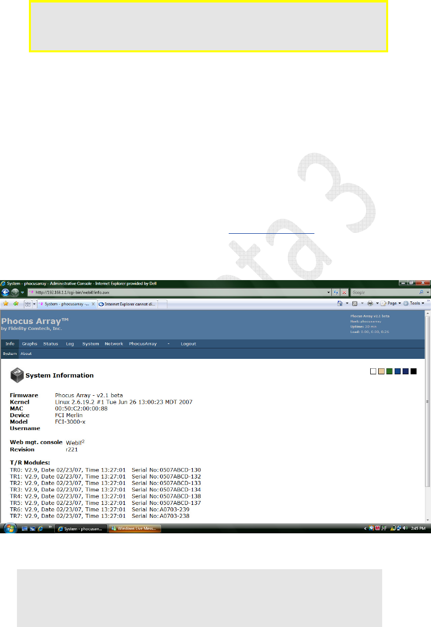
Figure 11 – Power Connections ..................................................................................................... 28
Figure 12 – System Information ..................................................................................................... 30
Figure 13 – System Configuration: Password Prompt ................................................................... 31
Figure 14 – System Configuration: Password Response .............................................................. 32
Figure 15 – Login Screen ............................................................................................................... 33
Figure 16 – System Settings .......................................................................................................... 34
Figure 17 – System Configuration ................................................................................................. 35
Figure 18 – System Configurations Examples ............................................................................... 36
Figure 19 – System Configuration Options .................................................................................... 37
Figure 20 – AP Router Configuration ............................................................................................. 38
Figure 21 – Client Router Configuration ........................................................................................ 39
Figure 22 – Ad Hoc Router Configuration ...................................................................................... 40
Figure 23 – Wireless Configuration – WEP ................................................................................... 41
Figure 24 – DHCP Server Configuration........................................................................................ 42
Figure 25 – Adding Hosts............................................................................................................... 43
Figure 26 – Configure Antenna ...................................................................................................... 44
Figure 27 – Manage Stations ......................................................................................................... 45
Figure 28 – Info > System: System Information ............................................................................. 47
Figure 29 – Info > About ................................................................................................................ 48
Figure 30 – Graphs > CPU ............................................................................................................ 49
Figure 31 – Traffic wifi0 .................................................................................................................. 50
Figure 32 – Device Status .............................................................................................................. 52
Figure 33 – Running Processes ..................................................................................................... 53
Figure 34 – Interfaces .................................................................................................................... 54
Figure 35 – DHCP Clients .............................................................................................................. 55
Figure 36 – Netstat ......................................................................................................................... 56
Figure 37 – Iptables ....................................................................................................................... 57

Phocus Array System Manual v2.1
9
Figure 38 – Syslog Settings ........................................................................................................... 58
Figure 39 – Syslog View ................................................................................................................ 59
Figure 40 – Kernel Ring Buffer ...................................................................................................... 60
Figure 41 – System Settings .......................................................................................................... 61
Figure 42 – Password Change ...................................................................................................... 62
Figure 43 – Backup and Restore ................................................................................................... 63
Figure 44 – Firmware Uploads ....................................................................................................... 64
Figure 45 – Reboot ........................................................................................................................ 65
Figure 46 – System Configuration ................................................................................................. 66
Figure 47 – Wireless Configuration ................................................................................................ 67
Figure 48 – DHCP Server Configuration........................................................................................ 68
Figure 49 – Host Configuration ...................................................................................................... 69
Figure 50 – Networking Tweaks .................................................................................................... 70
Figure 51 – Configure Antenna ...................................................................................................... 71
Figure 52 – Set Beamsteering Mode ............................................................................................. 72
Figure 53 – Monitor Associated Stations ....................................................................................... 74
Figure 54 – Manage Associated Stations ...................................................................................... 76
Figure 55 – View Loaded Patterns ................................................................................................. 77
Figure 56 – Logout ......................................................................................................................... 78
TABLE OF TABLES
Table 1 – Device Description and Specifications ........................................................................... 12
Table 2 – Features ......................................................................................................................... 13
Table 3 – Electrical Characteristics ................................................................................................ 14
Table 4 – Certifications, Compliance and Warranty ...................................................................... 15
Table 5 – Terms and Definitions .................................................................................................... 15
Table 6 – Default Wired Interface Network Parameters ................................................................ 29
Phocus Array System Manual v2.1
10
1 Overview
This is the installation and user manual for Fidelity Comtech’s Phocus Array System.
The Phocus Array System is an IEEE 802.11b/g radio and phased array antenna
system designed for outdoor use and housed in a single NEMA
1
rated package that can
act as an access point (AP) or as a client station.
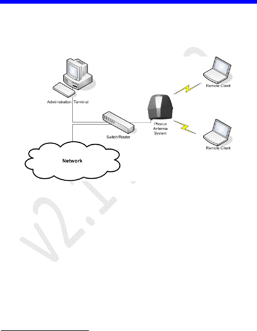
Figure 1 – Phocus Array Antenna System in a Wireless Access Point Application
The unique feature of the Phocus Array System is that its antenna radiation patterns
are electronically shaped and steerable
2
. This means that by giving the Phocus Array
System the appropriate software commands it can configure the antenna elements to
shape and steer patterns to become an Omnidirectional pattern, a 45-degree directional
pattern, or many more complex patterns and behaviors in any direction.
1
NEMA rating and IP rating
2
The ability to electronically shape and steer antenna patterns is also referred to as the Geo-I feature.
Phocus Array System Manual v2.1
11
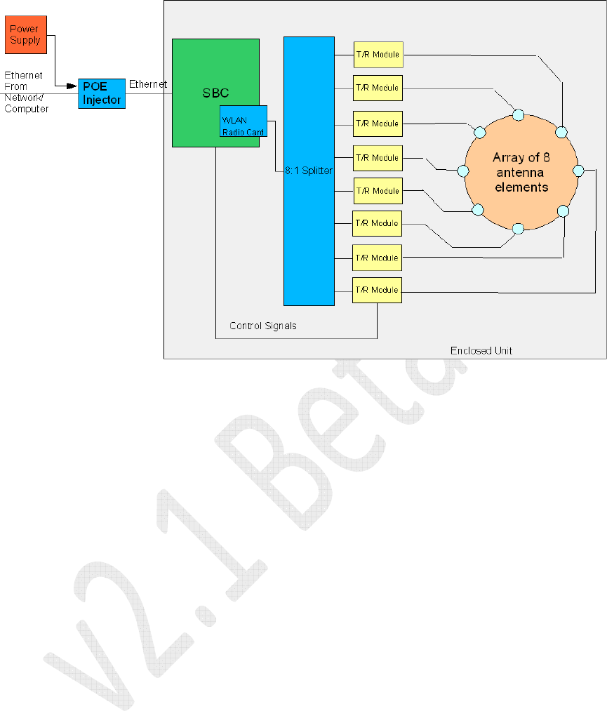
Figure 2 – Phocus Array System Block Diagram
The Phocus Array System consists of the following components contained in a sealed
outdoor enclosure:
• An embedded single board computer (SBC) running Linux-based software
• FlexVMT
o An IEEE 802.11b/g-based radio module wireless LAN (WLAN) card
o An 8:1 RF splitter
o Eight (8) T/R (transmit/receive) Modules that control the beam shaping
and steering
• An array of eight (8) antenna elements arranged in a circular pattern
Additionally, the system is shipped with an external power supply and Power Over
Ethernet (POE) Injector that combines Ethernet signals and the correct power supply
voltage to operate the unit. These two components should be mounted indoors
separately from the outdoor mounted Phocus Array System enclosure.
There are several ways of managing the Phocus Array System. The primary one is the
Administrative Console. This interface should be used to configure the Phocus Array
System and for simple monitoring, administration, and maintenance. Additionally,
there is a Secure Shell (SSH) interface to the SBC. The SSH interface requires
considerable Linux expertise to use and must be used with caution to avoid rendering
the system inoperable and possibly unrecoverable.

Phocus Array System Manual v2.1
12
The remainder of this manual gives a basic overview of beam shaping and steering,
walks you through the basic installation and configuration, explains the different
interfaces and tools, and gives a more detailed description of the operation of the
Phocus Array System. The appendices contain the default passwords, details of the
customized Linux distribution, and discussion of the direct software interfaces.
1.1.1 Device Description and Specifications
Table 1 – Device Description and Specifications
Power Requirements: Supplied external 120V AC Power Supply, 24 V DC
Output, 2.5 Amp
Dimensions (w/o attachment
hardware):
9.5” x 9.5” x 11” (24.1 cm x 24.1 cm x 28 cm)
Weight (w/o attachment
hardware):
10 lbs (4.5 kg) system
Pole Mounting kit
Wall Mounting kit
External Construction: Outdoor mountable, sealed, high-impact, UV painted,
ABS plastic radome over a powder-coated cast aluminum
base. Base and radome are joined with a neoprene seal.
Operating Environment: -40°C to 85°C (-40⁰F to 185⁰F); 0 – 100% relative
humidity, when used in conjunction with included
weatherproof Ethernet cable connector boot. Not designed
to be immersed in liquid.
EMC Rating: Designed to comply with FCC Part 15
Input Connections RJ-45 Ethernet
Wireless Protocols IEEE 802.11 b/g
TCP/IP v4
Wireless Security WEP 64, WEP 128, WPA (3DES), WPA2 (AES)
Antenna Technology FlexVMT

Phocus Array System Manual v2.1
13
1.1.2 Core Features
Table 2 – Features
Geo-Location
•
Geo-I—Dynamic Beam Steering and Beam Shaping
included
Reach Improvement
•
Phased array’s “Super-Omnidirectional” signal using
spatial integration provides up to 6.1 dB better
performance than traditional antenna diversity systems,
thereby doubling Reach in free space and balancing
coverage.
•
Focused signal’s range can increase up to 4 times over
the “super” Omnidirectional pattern’s Reach or 16 times
the coverage area
•
Link reliability also dramatically improves with a
focused beam
Interference Improvement
•
A focused directed or shaped beam reduces interference
by up to 88%
Privacy / Security
•
A focused directed or shaped beam keeps signal away
from threats
Data Packet Routing
•
Targeted user packet-by-packet data routing and beam
reconfiguration:
•
Reduces spectrum use
•
Enhances network capacity
•
Reduces signal intercept probability
Management and Software
Interface
•
Remote software/firmware UpGradeability using
browser-based administration, configuration, monitoring
and pattern selection; SNMP (Ethernet-Network, CPU,
Wireless MIBs); XML-RPC
•
UpGrades may use factory defaults of previously stored
settings
Power Consumption
•
Low power requirements simplify installation and
increase usage in mobile or remote applications

Phocus Array System Manual v2.1
14
Table 2 – Features
Ruggedized Package
•
Optimal for outdoor and mobile vehicle applications
Compact Size
•
Ideal for portable and vehicle systems and those that
require a small “wind sail” profile
1.1.3 Electrical Characteristics
Table 3 – Electrical Characteristics
EIRP - Effective Isotropic
Radiated Power
Restricted to 42 dBm to meet FCC requirements
(Capable of 45 dBm)
Coverage Patterns Standard 360º horizontal by 35º vertical, focused to 43º H.
Radiation Patterns Omnidirectional, 16 high-gain presets, and custom available
Dynamic Pattern
Reconfiguration
<100 µSecs
Frequency Bandwidth 2.400 GHz—2.484 GHz supporting IEEE 802.11 b/g
Data Rates—802.11 b and g* 1, 2, 5.5, 6*, 9*, 11, 12*, 18*, 24*, 36*, 48*, 54* Mb/sec
Antenna Gain 15 dBi maximum (43º HPBW azimuth)
Array Control Single Intel XScale 425 processor
Input Power Power over Ethernet (POE), 20 watts maximum at 48VDC
Power Consumption 9 Watts average, 20 Watts peak
Dynamic Pattern
Reconfiguration
Restricted

Phocus Array System Manual v2.1
15
1.1.4 Certifications, Compliance and Warranty
Table 4 – Certifications, Compliance and Warranty
Certifications Radio FCC - Part 15, MilSpec 810F
Compliancy Enclosure NEMA ???
Warranty System One year limited warranty
1.1.5 Definitions
The following acronyms, abbreviations, and terms are used in this manual:
Table 5 – Terms and Definitions
Term Definition
AP Access Point
AP Bridge Access Point Bridge – The Phocus Array System acts as a bridge
between two network segments: a wired network segment and a
wireless network segment. Generally DHCP is utilized for a network
based DHCP server
Ad Hoc Router The Phocus Array System is configured to connect in a peer-to-peer
fashion to another Ad Hoc Wireless station. This mode is often used to
create a dedicated wireless peer-to-peer link.
API Application Programming Interface
AP Router Access Point Router – The Phocus Array System acts as a router and
routes network traffic between two networks: a wired network and a
wireless network
Azimuthally Along the horizon.
CF Compact Flash.
Client Router The Phocus Array System is configured to act like a standard wireless
client.
DBm Decibels referenced to 1 mille watt
DHCP Dynamic Host Configuration Protocol. RFC 2131.
DNS Domain Name Server.
ESSID Extended Service Set IDentifier.
FCI Fidelity Comtech, Inc.
FlexVMT Flexible Vector Modular Technology – Patent #6,894,657
Geo-I Dynamic Beam Shaping and Steering

Phocus Array System Manual v2.1
16
Term Definition
GHz Giga Hertz
G.R.I.P.S. GeoLocation, Reach, Interference mitigation, Privacy/Security
IP Internet Protocol.
MAC Media Access Control
MADWiFi Multiband Atheros Driver for Wi-Fi
MilSpec Military Specification
NEMA National Electrical Manufacturers Association
NTP Network Time Protocol
POE Power Over Ethernet
Reach Describes how far away a wireless client can effectively receive and
transmit 802.11 b/g signals with a wireless infrastructure node.
RSSI Receive Signal Strength Indication.
SBC Single Board Computer.
SSH Secure Shell
State An antenna configuration compromised of a set of weights, one for
each T/R Module, plus system-level drive and gain parameters that
have been stored by the Phocus Array System and may be recalled.
TCP Transmission Control Protocol. RFC 793.
T/R Module Transmit/Receive Module –
a internal component of the Phocus Array
System that is responsible for adjusting phase and magnitude of RF
signals for one antenna element under the control of the SBC.
TCP Transmission Control Protocol. RFC 793.
UpDate UpDates are software or firmware code releases that include bug fixes
and minor feature enhancements. UpDates are always available to
Phocus Array System customers at no charge.
UpGrade UpGrades are software or firmware code releases that include new
features or feature enhancements. UpGrades are available to Phocus
Array System customers for a fee or under a Support Plan Agreement.
Weight A particular set of the two parameters (magnitude and phase) that
determine the basic behavior of a T/R Module.
WEP Wired Equivalent Privacy
Wi-Fi Wireless Fidelity.
WLAN Wireless Local Area Network

Phocus Array System Manual v2.1
17
2 Principles of Geo-I
(Beam Shaping and Steering)
Before discussing the Phocus Array System, it is helpful to have a basic understanding
of the beam shaping and steering “Geo-I” feature that differentiates the Phocus Array
System from other IEEE 802.11 compliant APs.
2.1 Theory
A phased array antenna is one that shapes and steers its beam by applying the same
signal to different antennas in an antenna system using different phases. When the
system combines two radio waves of the same frequency, the result depends on the
phase difference. If the two radio waves are in phase (their positive peak occurs at the
same time), the radio waves add. If they are 180 degrees out of phase (the positive
peak of one occurs at the same time as the negative peak of the other), they reduce. In
the latter case, if the two waves are the same amplitude, they will completely cancel
each other out. If the phase difference is in between, the result will be in between.
If there are more than two antenna elements, it is possible to create very complex
beam patterns by choosing the amplitude and phase of the signal applied to each
antenna element. The Phocus Array System uses an eight (8)-element antenna
FlexVMT in a uniform circular array configuration. This provides the ability to create
a directional beam (about 45 degrees wide) in any direction azimuthally (i.e. along the
horizon). It also has the ability to form an Omnidirectional antenna, such that the
signal can be transmitted in all directions simultaneously. It can also form much more
complex beam patterns. Finally, the system can control a received signal in exactly the
same way as it can a transmitted signal so that it can selectively receive from any
direction, all directions at once, etc.
2.2 Phased Array Technology
Fidelity Comtech’s small, patented light-weight Flexible Vector Modular Technology
(FlexVMT), is a circular 8-element focused array beam has a variable target footprint
from a standard 360º Omnidirectional pattern to an extended long-Reach focused 43º
pattern. The FlexVMT can electronically switch between steered or shaped patterns in
less than 100 µSecs on a packet-by-packet basis or be statically administered.
The beam pattern can also avoid other radiation patterns and sources, avoiding
interference while improving signal Reach and quality for better throughput
performance due to fewer packet retransmissions.
The FlexVMT Dynamic Antenna combines signals from all eight (8) antenna elements
to form each pattern, even a “super” Omnidirectional. This "spatial integration"
provides up to 6.1 dB better performance than traditional antenna diversity systems.

Phocus Array System Manual v2.1
18
2.3 Benefits of the FlexVMT (Phased Antennas in a Uniform
Circular Array Configuration)
The Phocus Array System product line, from Fidelity Comtech, Inc., utilizes second
generation wireless “Phased Array” technology contained within the patented
FlexVMT technology. The benefits of the FlexVMT technology (a Phased Array
antenna in a Uniform Circular Array configuration) is a feature set we refer to as
G.R.I.P.S:
G.R.I.P.S. is an acronym for the feature set and key benefits of the implementation of
the technology in any product. G.R.I.P.S. stands for GeoLocation, Reach,
Interference mitigation, Privacy and Security.
2.3.1 GeoLocation
Fidelity Comtech has implemented and is extending a premium GeoLocation feature
set based on the power of the FlexVMT technology. The current set provides three
levels of GEO capability with additional refinements coming soon. This document
presents high level definitions of the first three levels, with more details available in
the GeoLocation Datasheet.
GEO-I is the ability to dynamically shape, steer and extend the electronic beam used
in products implementing the FlexVMT technology. The shaping, steering and
extension is performed on a packet-by-packet basis using a dictionary of predefined
beam patterns (Custom patterns available).
2.3.2 Reach
The term “Reach” is used to describe how far away a wireless client can effectively
receive and transmit 802.11 b/g signals with a wireless infrastructure node.
The limits of Reach have to do with transmitted power, a radio receiver’s sensitivity or
rather its ability to distinctly recognize a unique transmission, and the amount of
signal interference. It is generally true that system powered APs, or system antennas,
are capable of much more radiated power and can “extend” or “push” their electronic
beam signal much further than battery powered mobile devices.
Thus, the shortest distance an AP and a mobile device can actively and reliably
communicate is known as its ‘Reach”.
To increase Reach; transmission, reception, and interference must be improved. To
increase transmission distance compared to a simple Omnidirectional or diversity
antenna, a phased array antenna focuses the signal energy in a desired direction. While
Omnidirectional signals send the energy in all directions, a phased array antenna uses
its multiple antenna elements, transmitters, and receivers to cooperatively “boost” the
signal in a desired direction and diminish the signal in others. Similarly, receiver
“gain” is accomplished when the phased array’s elements and receivers act together to
receive a signal.

Phocus Array System Manual v2.1
19
Dynamic phased array antennas, specifically the FlexVMT technology used within
products such as the Phocus Array System offer nearly four (4) times the Reach of a
common Omnidirectional or diversity antenna.
2.3.3 Interference Mitigation
The key to Reach, both for the Mobile Device and the APs, is the ability of the
receivers to discriminate a specific “Tuned” signal at its weakest point in a
surrounding full of electronic noise from other radiated signals from the general
environment and universal bodies like the sun.
The main reason dynamic antennas have extended Reach over traditional
Omnidirectional antennas is because shaped steered and extended beams produce
much lower noise environments. Signal-to-Noise Ratios (SNR) may be improved by
putting the desired signal only in the area of concern and not bleeding over into other
environments. Thus, signal clarity or reliability is greatly enhanced.
The beam pattern can also avoid other radiation patterns and sources, avoiding
interference while improving signal Reach and quality for better throughput
performance due to fewer packet retransmissions.
2.3.4 Privacy / Security
The first rule of wireless security is to prevent others access to the transmitted signal.
Omnidirectional antennas commonly used in APs radiate in a full 360º pattern that
resembles a “donut-like” shape. The dynamic beam can be shaped, steered, and
extended to cover only the desired “footprint” and keep the signal from “bleeding”
over into unwanted spaces. Thus, the system administrator can “Avoid” other areas
providing privacy. Signal Avoidance is step one. The FlexVMT-based dynamic
antennas electively directs its signal improving security and privacy dramatically by
reducing eavesdropping possibilities and interference. Signal Avoidance also helps
minimize the noise “pollution” for other environments maintaining their Reach.
Signals received in a multi-path
3
are both “in and out” of phase when distributed
across a Phased Array in a Uniform Circular Array configuration providing contiguous
signal receptions where a standard panel or di-pole antenna would have dropouts of
signal loss. The Phocus Array System is ideal for “Multipath” environments” In these
environments at least some antenna elements in the circular array will be able to
capture the signal. Thus signal Reach and fidelity is consistently maintained.
2.4 The Phocus Array System Implementation
The Phocus Array System consists of a single radio (the IEEE 802.11b/g module)
which handles both transmit and receive functions (refer to Figure 2). The antenna
terminal of the radio connects to the common terminal of an eight (8)-way splitter.
3
Multipath is when many signals from the same source are received in and out of phase caused by
reflections of the signals in the transmission path. (i.e. Container yards have many reflected signals
from a radiated source)
Phocus Array System Manual v2.1
20
Each of the other terminals of the splitter connects to a T/R Module that connects to an
antenna. The T/R Module is a vector modulator and a bi-directional amplifier that is
directed by the software.
The Phocus Array System can control its beam patterns using two basic modes: static
and dynamic. In static mode, the beam pattern is configured and all radio operations
are conducted using that pattern. The system remains fixed in the designated beam
pattern until directed to change via the Administrative Console. In dynamic mode, the
beam pattern can be different for each radio communication (packet) with each client.
The dynamic mode obviously requires much closer cooperation between the radio and
the antenna.
Fidelity Comtech has pre-computed a number of beam patterns for the Phocus Array
System. Seventeen of these patterns come pre-loaded into the Phocus Array System as
Omnidirectional and sixteen Co-Phasedirectional patterns. You may purchase and load
additional patterns. Contact FCI for more information. The following is brief
description of some the factory default patterns:
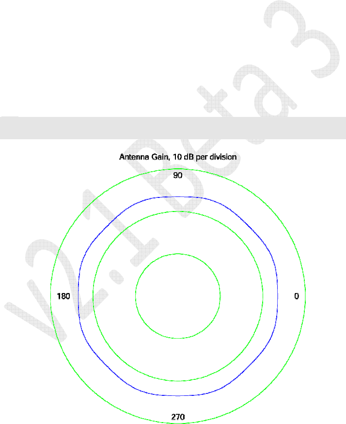
• Omnidirectional Pattern: Transmits/receives in a 360-degree circle. This
pattern is pre-programmed as Omnidirectional, 0 Phase and is illustrated in
Figure 3.
Note
: The pattern is illustrated by the blue line between the concentric green polar plot
divisions. The antenna is implied at the center of the plot.
Figure 3 – Omnidirectional Antenna Pattern – “0 Phase”
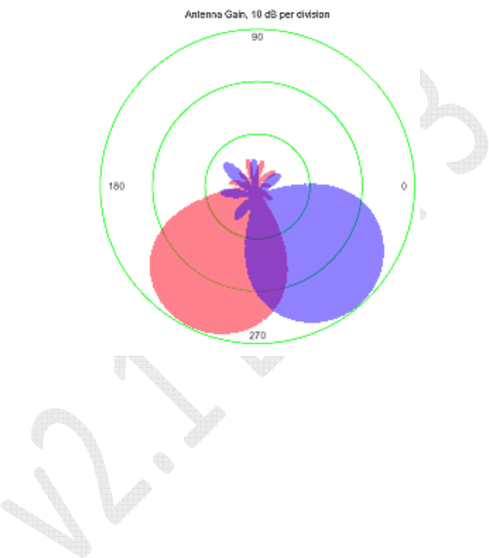
• Co-Phase Unidirectional Patterns (Co-Phase 0 deg through Co-Phase 337.5
deg): These patterns transmit/receive primarily in one direction. Each of the 16
Phocus Array System Manual v2.1
21
standard Co-Phasepatterns has a beam that is nearly identical in shape (the
half-power beamwidth for each is approximately 43 degrees), but each pattern
is rotated counterclockwise 22.5 degrees more than the one before it. You can
change the direction of the beam by changing the active pattern (e.g.: from Co-
Phase 22.5 deg to Co-Phase 67.5 deg). The following example (see Figure
4) illustrates the directional effect of changing the antenna from pre-
programmed beam pattern Co-Phase 225 deg (red) to Co-Phase 315 deg
(blue).
Figure 4 – Factory Default Antenna Patterns “Co-Phase 247.5” and “Co-Phase 315”
2.5 Additional Beam Patterns
The factory default antenna patterns provide a balance between beam width, Reach,
and side lobe power, making them suitable for many applications.
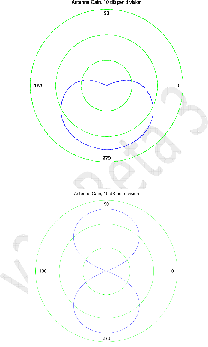
Finally, in addition to the factory default and the dynamically synthesized patterns
described above, custom beam patterns can be designed and installed with various
benefits and trade offs in mind. Two of the many possibly synthesizable patterns are
illustrated in Figure 5 and Figure 6. Please contact Fidelity Comtech with your
antenna pattern synthesis needs.
Phocus Array System Manual v2.1
22
Figure 5 – Sector Antenna Pattern
Figure 6 – Two Lobe Pattern
Phocus Array System Manual v2.1
23
3 Installation and Hardware Set Up
Unpack the Phocus Array System from its shipping container. The system should
consist of the following parts:
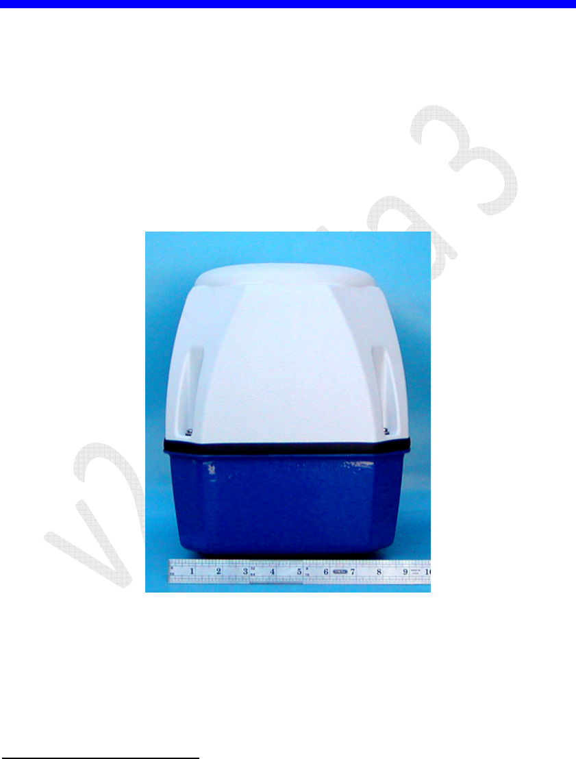
• Phased array antenna in outdoor enclosure (see Figure 7)
• Weatherproof Ethernet cable connector (see Figure 8)
• Power over Ethernet power injector (see Figure 8)
• Power cable (see Figure 8)
• Mounting bracket, either right angle (see Figure 9) or pole (see Figure 8)
• Four bolts to attach bracket to antenna (see Figure 9 or Figure 8)
4
Figure 7 – Antenna in Outdoor Enclosure
4
Note: The bolts for mounting the pole mounting kit to the Phocus Array System are longer than the
bolts needed to mount the right angle bracket.
Phocus Array System Manual v2.1
24
Figure 8 – Power Injector, Cable, Pole Mounting Bracket, and Accessories
Figure 9 – Right Angle Mounting Hardware
Note: The bolts for mounting the pole mounting kit to the Phocus Array System
are longer than the bolts supplied to mount the right angle bracket.

Phocus Array System Manual v2.1
25
3.1 Installation Considerations
3.1.1 Safety
Warning: Installation of this product near power lines is dangerous! For your safety,
follow the installation directions.
3.1.2 How to Install your Phocus Array System Safely
The following installation precautions and guidelines are extracted from the
Recommendations of the U.S. Consumer Product Safety Commission on installing
antennas.
These safety recommendations apply to all antennas.
Each year, hundreds of people are killed, mutilated, or receive severe and permanent
injuries when attempting to install an antenna. In many of these cases, the victim was
aware of the danger of electrocution, but did not take adequate steps to avoid the
hazard.
For your safety, and to help you achieve a good installation, please read and follow the
safety precautions below. They may save your life!
That this is not complete list of instructions, precautions, and installation guidelines
necessary to safely and effectively install the antenna. You should consult a
professional, as well as observe local and national code requirements.
8. If you are installing an antenna for the first time, please, for your own safety as
well as others, seek professional assistance. The professional can explain
which mounting method to use for the size and type of antenna you are about
to install.
9. Select your installation site with safety, as well as performance, in mind.
REMEMBER: ELECTRIC POWER LINES AND PHONE LINES LOOK
ALIKE. FOR YOUR SAFETY, ASSUME THAT ANY OVERHEAD LINES
CAN KILL YOU.
10. Call your electric power company. Tell them your plans and ask them to come
take a look at your proposed installation. This is a small inconvenience,
considering YOUR LIFE IS AT STAKE.
11. Plan your installation procedure carefully and completely before you begin.
Successful raising of a mast or tower is largely a matter of coordination. Each
person should be assigned a specific task, and should know what to do and
when to do it. One person should be designated as the leader/coordinator of the
operation to call out instructions and watch for signs of trouble.
12. When installing your antenna, REMEMBER: DO NOT USE A METAL
LADDER. DO NOT WORK ON A WET OR WINDY DAY. DO DRESS
PROPERLY: shoes with rubber soles and heels, rubber gloves, long sleeved
shirt or jacket.

Phocus Array System Manual v2.1
26
13. If the assembly starts to drop, get away from it and let it fall. Remember, an
antenna, mast, cable, and metal guy wires are all excellent conductors of
electrical current. Even the slightest touch of any of these parts to a power line
completes an electrical path through the antenna and the installer – THAT’S
YOU!
14. If ANY PART of the antenna system should come in contact with a power line,
DON’T TOUCH IT OR TRY TO REMOVE IT YOURSELF. CALL YOUR
LOCAL POWER COMPANY. They will remove it safely.
If an accident should occur with the power lines, call for qualified emergency help
IMMEDIATELY.
3.1.3 Placement and Performance
Placement of the Phocus Array System can affect performance. Keep in mind that the
number, thickness, and location of walls, buildings, trees, or other objects that wireless
signals pass through or reflect off, may limit the range. Typical ranges vary depending
on terrain, proximity to objects, types of materials and background RF noise. The key
to maximizing range is to follow these basic guidelines:
Clear line-of-sight between the Phocus Array System and your network devices gives
the best performance.
Keep the number of walls and ceilings between the Phocus Array System and other
network devices to a minimum - each wall or ceiling can reduce your range from 3-90
feet (1-30 meters.) Position your devices so that the number of walls, trees, etc. is
minimized.
Be aware of the direct line between network devices. A wall that is 1.5 feet thick (.5
meters), at a 45-degree angle appears to be just over 2 feet (.6 meters) thick. At a 2-
degree angle it looks over 42 feet (14 meters) thick! Position devices so that the signal
will travel straight through a wall or ceiling (instead of at an angle) for better
reception.
Building materials can impede the wireless signal - a solid metal door or aluminum
studs may have a negative effect on range. Try to position wireless devices and
computers with wireless adapters so that the signal passes through drywall or open
doorways and not other materials.
Keep your product away (at least 3-6 feet (1-2 meters)) from electrical devices or
appliances that generate extreme RF noise. (i.e. Microwave ovens…)
3.2 Installation Procedure
1. Attach the antenna to the bracket using the supplied bolts and fasten the
bracket securely in its final location. There is an orientation tab on the bottom
of the Phocus Array System housing that marks the 0 degree direction (see
Figure 10).
Phocus Array System Manual v2.1
27
Notes: Washers are not supplied with these bolts because threads in the base of the
Phocus Array System housing are self-locking.
The pole bracket requires a one-inch OD pipe with an NPT thread.
If the Phocus Array System is to be used with the pole bracket, be aware that
the pipe threads in the bracket are tapered and the bracket should be attached
to the Phocus Array System housing with the thicker center pad away from
the housing.
Figure 10 – Bottom View showing Orientation Tab
2. Install the supplied Ethernet connector by inserting the rubber sleeve through
the cable access hole in the bottom of the housing,
3. Attach the supplied Ethernet connector to the end of a CAT5 (or better) cable.
If this is a temporary connection just to configure the antenna, an ordinary RJ-
45 connector will work.
5
If the connection is permanent, use the supplied
connector to ensure a weatherproof connection.
Caution: Be sure to use outdoor rated CAT5 cable unless the antenna is to be
installed in a sheltered location (cable will not be exposed to moisture or
direct sunlight).
4. Put a standard RJ-45 connector on the other end of the CAT5 cable.
Caution: This cable should be no more than 100 feet in length. This limitation is
less than that normally specified for Ethernet because the Power Over
Ethernet (POE) limits the length of the cable.
5
Note if a direct connection is needed to a PC use a cross over Ethernet cable between the PC and the
POE Injector.
Phocus Array System Manual v2.1
28
5. Plug this cable into the RJ-45 port on the side of the power injector that has the
indicator lights (see Figure 11).
Figure 11 – Power Connections
6. Plug the power supply in to the power jack on the power injector. Use a
standard Ethernet cable to connect the other RJ-45 connector on the power
injector to the network.
Note: If the antenna is going to be connected directly to a laptop or desktop
computer to configure it (as opposed to going through a switch or a hub), a
crossover (reverse) Ethernet cable will be necessary.
Data Cable
Data and Power Cable
POE Power
Injector
Phocus Array

Phocus Array System Manual v2.1
29
4 Configuration and Software Setup
This section describes a startup procedure for those who want to immediately bring up
a Phocus Array System on their network. For a complete overview of the
Administrative Console that is used to do this quick configuration, refer to Section 5,
Using the Administrative Console.
Note
: English is the only language supported in this release.
The Phocus Array System comes pre-configured with the following wired interface
network parameters:
Table 6 – Default Wired Interface Network Parameters
IP Address 192.168.1.1
Netmask 255.255.255.0
Gateway <nil>
4.1 Configuration Sequence and Options
Initial configuration consists of several required steps, as well as some optional steps:
1. Connect the Phocus Array System to your computer via a networking interface
2. Administer the password
3. Login
4. Administer the System Settings
5. Select the System Configuration
a. AP Bridge
b. AP Router
c. Client Router
d. Ad Hoc Router
6. Administer the Wireless Adapter Configuration
7. DHCP Server Configuration (optional)
8. Adding Hosts (optional)
9. Select the Antenna Configuration
10. Manage Stations (optional)
Phocus Array System Manual v2.1
30
Caution: When configuring the Phocus Array System, you must click the
Save
Changes
button and then click
Apply Changes
for settings to take effect.
At your discretion, you may
Save Changes
for several pages and submit
them all by clicking
Apply Changes
once.
4.2 Performing Initial Configuration
Use this section to connect and configure the Phocus Array System.
4.2.1 Connecting the Phocus Array System to your Computer
1. Setup a computer that will be used to administer the Phocus Array System on
the same local network as the Phocus Array System. This computer must have
an IP address in the same class C network as the Phocus Array System (e.g.,
192.168.1.100) as well as the appropriate Netmask and Gateway settings. Use
the appropriate commands/settings for your administration machine’s
operating system.
2. Open a Web browser and type the URL http://192.168.1.1.
3. If a message about an invalid certificate is displayed, proceed anyway.
4. The Phocus Array System Information screen displays.
Figure 12 – System Information
Note
: On all screens in the Administration tool there is a series of small colored boxes on
the upper right hand side of the screen. These boxes are for the user to change the
“skin” color of the displayed screens to optimize them for easy viewing, extended
battery life of mobile units or color blindness. Just click on the color selection that
works best for your current situation.
Phocus Array System Manual v2.1
31
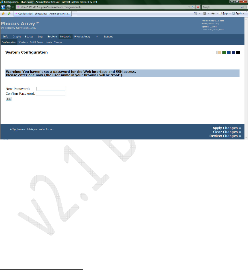
4.2.2 Administering the Password
1. Click the Network tab.
2. When prompted for a New Password, type in your password (using good
password guidelines) and confirm it.
6
3. Click the Set button.
Figure 13 – System Configuration: Password Prompt
6
Password guidelines include using:
• Eight (8) or more characters including letters, numerals and non-alphanumeric characters.
• Uppercase on more than the first letter. Passwords are case sensitive.
• The first letter from each word in a phrase (e.g., C$200wpG, represents "Collect $200 when
passing Go").
Phocus Array System Manual v2.1
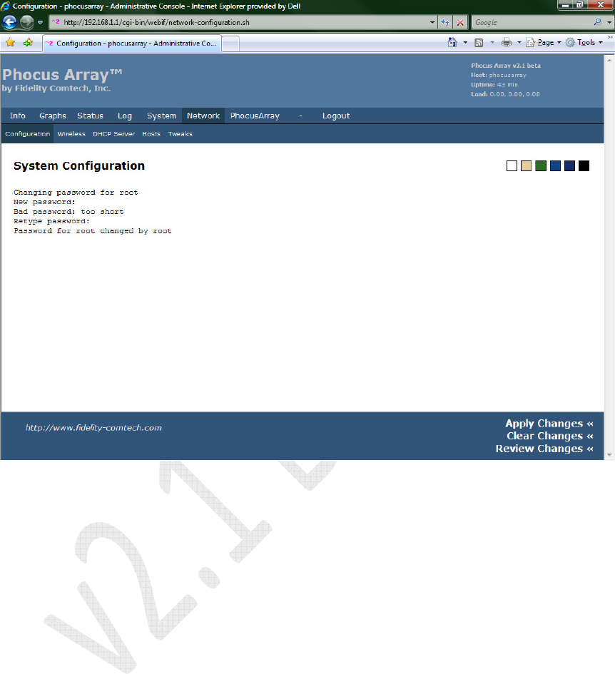
32
4. The System Configuration screen will display progress as the password is
accepted.
Figure 14 – System Configuration: Password Response
Phocus Array System Manual v2.1
33
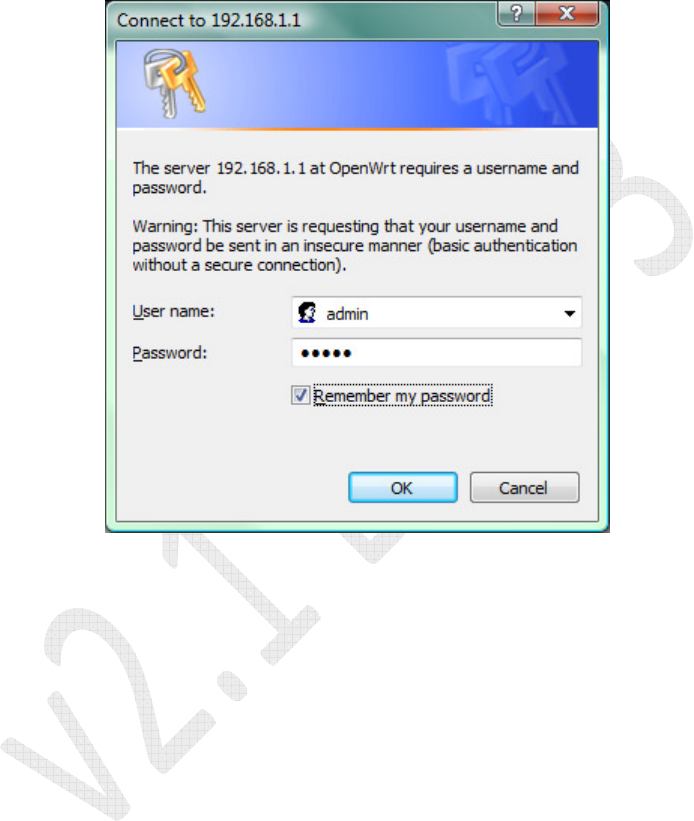
4.2.3 Login
1. The Login screen displays.
2. Type admin for the User name and your administered password for the
Password.
3. Click the OK button.
Figure 15 – Login Screen
4. The System Information screen displays.
Phocus Array System Manual v2.1
34
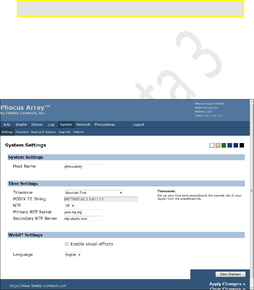
4.2.4 System Settings
1. Click the System tab.
2. Click Settings in the System menu bar.
3. Enter the desired Host Name for the Phocus Array System. This name will
help you identify this system.
Limits/caution: Only letters and numerals may be used for the
Host Name
(a-z, A-Z and 0-
9). No spaces or special characters may be used.
4. Select your Timezone from the drop-down list.
Optionally, NTP (Network Time Protocol) may be turned on to synchronize the
system’s time with a networked source. To enable and NTP:
a. Select NTP “On” from the drop-down list
b. Enter the address of the nearest NTP Server.
5. Click the Save Changes button.
6. Click Apply Changes.
Figure 16 – System Settings