Firetide 5020-1 Dual band outdoor Access Point User Manual User Guide
Firetide Inc. Dual band outdoor Access Point User Guide
Firetide >
User Guide
Firetide
Manual Revision 1.0d1 2012-09-03
The contents of this Installation Guide are subject to change without notice.
Please refer to the Firetide partners web site, partners.retide.com, for current versions.
Installation & Setup Guide
HotPort 5020 Mesh Node
HotPort 5020 MIMO Outdoor Mesh Node
2 HotPort 5020 User Guide
Safety Instructions Firetide units must be installed by a qualified professional. Failure to install
properly may result in equipment damage, personal injury, or death.
POWER LINES CAN BE LETHAL
Do not install Firetide products where possible contact with power lines can be made. Antennas, poles, towers,
guy wires, or cables may lean or fall and contact these lines. People may be injured or killed if they are touching or
holding any part of equipment when it contacts electric lines. Make sure there is NO possibility that equipment or
personnel can come in contact directly or indirectly with power lines.
ASSUME ALL OVERHEAD LINES ARE POWER LINES
The horizontal distance from a tower, pole or antenna to the nearest power line should be at least twice the total
length of the pole/antenna combination. This will ensure that the pole will not contact power if it falls either dur-
ing or after installation.
SURVEY THE SITE
Look over the entire site before beginning any installation and anticipate possible hazards. Never assume anything
without checking it out for yourself! Don’t take shortcuts!
TO AVOID FALLING, USE SAFE PROCEDURES WHEN WORKING AT HEIGHTS ABOVE
GROUND
•Select equipment locations that will allow safe and simple installation.
•Don’t work alone. A friend or co-worker can save your life if an accident happens.
•Don’t attempt repair work when you are tired. Not only will you be more careless, but your primary diagnostic
tool - deductive reasoning - will not be operating at full capacity.
•Use approved non-conducting ladders, shoes, and other safety equipment. Make sure all equipment is in good
repair.
•If a tower or pole begins falling, don’t attempt to catch it. Stand back and let it fall.
•If anything such as a wire or pole does come in contact with a power line, DON’T TOUCH IT OR AT-
TEMPT TO MOVE IT. Instead, save your life by calling the power company.
•Don’t attempt to erect antennas or towers on windy days.
•MAKE SURE ALL TOWERS AND POLES ARE SECURELY GROUNDED, AND ELECTRICAL CABLES
CONNECTED TO ANTENNAS HAVE LIGHTNING ARRESTORS. This will help prevent fire damage or
human injury in case of lightning, static build-up, or short circuit within equipment connected to the antenna.
The HotPort mesh node has built-in lightning protection. Be sure that any other equipment connected to the
HotPort mesh node also has the same level of protection.
•The base of the antenna pole or tower must be connected directly to the building protective ground or to one
or more approved grounding rods, using 10 AWG ground wire and corrosion-resistant connectors.
•Refer to the National Electrical Code for grounding details.
IF AN ACCIDENT SHOULD OCCUR WITH THE POWER LINES
•DON’T TOUCH THAT PERSON, OR YOU MAY BE ELECTROCUTED.
•Use a non-conductive dry board, stick, or rope to push or drag them so they no longer are in contact with elec-
trical power.
•Once they are no longer contacting electrical power, administer CPR if you are certified.
•Immediately have someone call for medical help.
3
Contents
1 System Overview .........................................................................................4
Mesh Design and Software Conguration ....................................................4
2 HotPort 5020 Installation .................................................................................5
Antenna Installation .........................................................................5
Installing the Radio Unit .....................................................................6
Connecting the Antennas ....................................................................7
Appendix A HotPort 5020 Specications ......................................................................8
Appendix B Regulatory Notices ............................................................................. 10
DFS Rules ..................................................................................11
Appendix C Limited End User Product Warranty ............................................................. 14
4 HotPort 5020 User Guide
The Firetide HotPort 5020 is a member of Firetide’s HotPort family of
wireless mesh nodes. It offers features similar to Firetide’s HotPort 7000
Series in a lower-cost unit.
Fundamentally, a Firetide mesh network gives you the convenience of a
wired-Ethernet switch combined with the flexibility of wireless technology.
A simple mesh network can be set up in minutes, with little more effort
than it takes to deploy an Ethernet switch. At the same time, Firetide offers
advanced features to enhance security, quality of service, and manageability.
This design makes the mesh ideal for any location where network cabling is
too difficult or expensive to install. HotPort networks operate indoors and out,
in the 900 MHz, 2.4, 4.9 (public safety), and 5 GHz bands. With its self-healing
capabilities and trac-prioritization options, a HotPort mesh network readily
satises the demands of high-bandwidth/low-latency applications, such as video,
voice, and data.
In addition, Firetide meshes support mobile mesh nodes, mobile 802.11
clients, and roaming. With this capability, nodes in a Firetide mesh can
move rapidly from zone to zone.
Complete Stand-Alone System
A Firetide mesh is a self-contained a fully-functional Ethernet switch, us-
ing a wireless backplane for its interconnect. There is no master node, nor
does the system require a computer or other management device. Thus, the
system is highly fault-tolerant; loss of a single radio will not bring down
the mesh.
Mesh Design and Software Conguration
For information on how design your mesh and configure your HotPort
5020 mesh nodes, refer to the the HotView Pro Reference Guide, available
from Firetide.
1 System Overview
Figure 1.1 HotPort 5020
outdoor MesH node
HotPort 5020 Installation 5
This appendix shows a typical installation. Details will vary depending on
antenna type.
The assembly must be grounded. If the mast is not already properly ground-
ed, you will need appropriate grounding hardware. Consult local codes.
The HotPort 5020 units have three antenna connectors for each radio. Each
HotPort 5200 unit should be installed with its antenna on a sturdy pole or
mast. It does not matter whether you install the antenna first or the radio
unit first. In all cases, antennas should be installed by a qualified profes-
sional. Outdoor installations MUST have code-approved grounding and
lightning-protection systems.
Antenna Installation
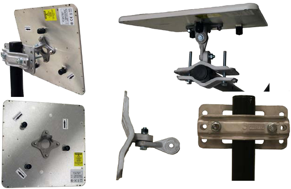
An assembled and mounted antenna is shown in Figure 1.2. The mount-
ing systems consists of a pole clamp assembly, a pivot link, and an antenna
bracket. These are shown in Figure 1.3.
Begin assembly by attaching the pivot link to the pole clamp assembly. Use
a flat washer under the bolt head, and under the nut use a flat washer and
lock washer.
Next, attach the pole clamp assembly to the pole. Again, use a flat washer
under the bolt heads, and under the nuts use a flat washer and lock washer.
Mount the antenna bracket to the antenna such that the mounting lug is
horizontal when the top of the antenna is up. Antenna polarizations must
match between the two ends of a link.
table 1.1 installation tools
1/2-inch open-end wrench
7/16-in open-end wrench
3/8-inch open-end wrench
Phillips screwdriver
Channel-lock or slip-joint pliers
RJ-45 crimping tool and male
plug
Waterproong tape or mastic for
RF connections.
Figure 1.2 Mounted antenna
Back and top views
Figure 1.3 antenna witH
bracket; two-Piiece angle
bracket; Ploe claMPs
2 HotPort 5020 Installation
6 HotPort 5020 User Guide
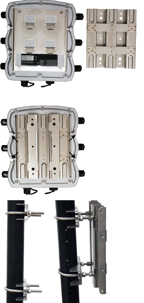
Installing the Radio Unit
Hooks (4) Hook Attachments
(4)
Radio Unit with
Mounting Plate
Plate for Pole
or Wall Mount
Captive Screws (4)
Figure 1.4 tHe HotPort 5020
is sHiPPed witH a two-Piece
Mounting Plate already attacHed.
Loosen the four fasteners, two on each
side, to remove the hook-attachment
plate. The captive screws are tight; you
will need channel-lock or slip-joint
pliers.
Figure 1.5 attacH two u-bolt
asseMblies to tHe Mounting Pole.
The U-bolts are large enough to
accomodate large poles; if you are
mounitng on a smaller-dialmeter pole,
you must either cut the U-bolts to
length or use four additional spacer
nutes.
Now you can hang the radio unit on
the bracket, and tighten the four cap-
tive screws.
Figure 1.6 tHe radio unit
Mounts witH a two-Piece Mount-
ing asseMbly.
One half of the assembly is perma-
nently attached to a pole or wall; the
second half, on the radio itself, hooks
over the first.
HotPort 5020 Installation 7
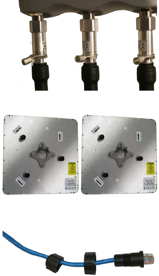
Figure 1.7 cable-to-radio
connections
Connect the radio unit to the an-
tenna using the supplied cables.
The cables are equipped with light-
ning-arrestor units, and should be
installed with the arrrestors con-
nected to the radio unit, not the
antennas.
Figure 1.8 tHe Final steP is
to Fabricate tHe weatHerProoF
etHernet connect.
Thread the cable as shown, and then
attach it to the HotPort 5020 radio
unit.
Connecting the Antennas
11
23
32
Figure 1.9 cable connection
Pattern is critical.
You must use the Radio 2 antenna
connectors; these are on the right side
of the unit when viewed from the
front. The panel antennas included
with the HotPort 5020 are ‘handed’;
the individual antenna connections
on the radio unit must be connected
to the antenna in a specific way, and
it is slightly different on each end of
the link.
On one end of the link, connect the
three antenna leads as shown in red.
On the other end, connect them as
shown in green. Not that this reverses
connections 2 and 3; this preserves
matching antenna polarization.
11
23
32

8 HotPort 5020 User Guide
Appendix A HotPort 5020 Specications
table 1.2 wireless interFace
sPeciFications
Model Use
HotPort 5020 Outdoor, Worldwide, Radio 2: 5 GHz
Bands Frequency (GHz) Restrictions
802.11a
802.11n
5.25-5.35
5.725-5.825
4.9-5.090
4.94-4.990
Japan only
US Public Safety
5.470-5.725 ETSI 301.893, U-NII
Bands Max TX Power
802.11a 5.725-5.825 UNII-3
802.11n
5.470-5.735 UNII
5.25-5.36 M UNII-2
26 dBm
26 dBm
24 dBm
23 dBm
23 dBm
23 dBm
802.11b 2.412-2.484 24 dBm
802.11g 2.412-2.484
802.11n
26 dBm
26 dBm
SUPPORTED DATA RATES & STANDARDS
• 802.11a6/9/12/18/24/36/48/54Mbps
• 802.11aCapableofswitchingto1⁄4and1⁄2ratesfor4.940–4.990
GHzPublicSafetyBand
• 802.11g6/9/12/18/24/36/48/54Mbps
• 802.11n6.5/13/19.5/26/65/130(20MHzLGB)
7.2/14.4/21.7/28.9/72.2/144(20MHzSGB)
13.5/27/40.5/54/135/270(40MHzLGB)
15/30/45/60/150/300(40MHzSGB)
• NetworkStandards:IEEE802.11a/d/e/f/h/i/n
• Security:WPA;64/128/256w/TKIP,AES
POWER
• 48VDCviaDCconnecteror802.3afPoE
ENVIRONMENTAL
• Humidity(non-condensing):10%to90%
• Storagehumidity(non-condensing):5%to95%
• Maximumaltitude15,000feet(4600meters)
NETWORK PORT
• One10/100/1000MbpsEthernetportwithweatherproofconnector
• IEEE802.3,802.3ucompliant
• CSMA/CD10/100/1000autosense

9
Firetide Mesh nodes may be reset to factory parameters. This is useful when return-
ing a unit from eld service or in recovering a unit you cannot communicate with.
To reset a unit, apply power and wait for the unit to fully boot. This takes 60 to 90
seconds. Use a paperclip to press and hold the reset button for 15 seconds. Wait for
the units to reboot before removing power.
ENCLOSURE
• CastaluminumNEMA-4X/IP66enclosure
• SixN-typeantennaconnectors
• Weatherproof48VDCpowerconnector
• Weight:3.75lbs(1.7Kg)withbracket
• Dimensions:8.2”x8.6”x2”(205x214x100mm)
SECURITY, AUTHENTICATION AND ENCRYPTION
• 802.11i,WPA2
• 40-bit,104-bitWEPkeys
• SSIDsuppression
NETWORK PORTS
• One10/100/1000autosenseBase-Tport
• IEEE802.3,802.3atbasedPoE
10 HotPort 5020 User Guide
ThesedevicescomplywithPart15oftheFCCRules.Operationissubject
tothefollowingtwoconditions:
• Thisdevicemaynotcauseharmfulinterference.
• Thisdevicemustacceptanyinterferencereceived,includinginterfer-
encethatmaycauseundesiredoperation.
Thisequipmenthasbeentestedandfoundtocomplywiththelimitsfora
ClassAdigitaldevice,pursuanttoPart15oftheFCCRules.Theselimits
aredesignedtoprovidereasonableprotectionagainstharmfulinterference.
Thisequipmentgenerates,usesandcanradiateradiofrequencyenergyand,
if not installed and used in accordance with the instructions, may cause
harmfulinterferencetoradiocommunications.However,thereisnoguar-
antee that interference will not occur in a particular installation. If this
equipmentdoescauseharmfulinterferencetoradioortelevisionreception,
whichcanbedeterminedbyturningtheequipmentoffandon,theuseris
encouragedtotrytocorrecttheinterferencebyoneormoreofthefollow-
ingmeasures:
• Reorientorrelocatethereceivingantenna.
• Increasetheseparationbetweentheequipmentandreceiver.
• Connecttheequipmentintoanoutletonacircuitdifferentfromthat
towhichthereceiverisconnected.
• Consultthedealeroranexperiencedradio/TVtechnicianforhelp.
ToensurecompliancewiththeFCC’sRFexposurelimits,theantennaused
forthistransmittermustbeinstalledtoprovideaseparationdistanceofat
least76cmfortheHotPort5020,fromallpersonsandmustnotbeco-
locatedoroperatedinconjunctionwithanyotherantennaortransmitter.
Installersandusersmustfollowtheseinstructions.
AnymodificationsmadetothisdevicethatarenotapprovedbyFiretide,
Inc.mayvoidtheauthoritygrantedtotheuserbytheFCCtooperatethis
equipment.
Antenna(s)fortheModel5020outdoorunitmustbeinstalledbyaquali-
fiedprofessional.Operationoftheunitwithnon-approvedantennasisa
violationofU.S.FCCRules,Part15.203(c),CodeofFederalRegulations,
Title47.
一、經型式認證合格之低功率射頻電機,非經許可,公司、商號或使用者均不
得擅自變更頻率、加大功率或變更原設計之特性及功能。
二、低功率射頻電機之使用不得影響飛航安全及干擾合法通信;經發現有干擾
現象時,應立即停用,並改善至無干擾時方得繼續使用。
前項合法通信,指依電信法規定作業之無線電通信。
低功率射頻電機須忍受合法通信或工業、科學及醫療用電波輻射性電機設
備之干擾。
Appendix B Regulatory Notices
FCC Class A Notice
FCC Part 15 Note
FCC Radiation Exposure
Modications
Installation
NCC Statement

11
This Class A Digital apparatus meets
all the requirements of the Canadian
Interference-Causing Equipment Regu-
lations.
CetappareilnumeriquedelaclasseAre-
spectelesexigencesduReglementsurle
materialbroilleurduCanada.
The device for operation in the band
5150-5250MHzisonlyforindooruse
to reduce the potential for harmful in-
terferencetoco-channelmobilesatellite
systems.
L’artificepourl’opérationdanslabande
5150-5250 MHz est seulement pour
l’utilisationensallepourréduirelepo-
tentielpourl’interférencemalfaisanteau
radiotéléphone de co-canal les systèmes
satellites.
The maximum antenna gain permit-
tedfordevicesinthebands5250-5350
MHzand5470-5725MHzshallcomply
withtheEIRPlimit.
l’augmentation d’antenne maximum
permisepourlesartificesdanslesbandes
5250-5350MHzet5470-5725MHzse
plieraàlalimited’e.i.r.p.
The maximum antenna gain permitted
fordevicesintheband5725-5825MHz
shallcomplywiththeEIRPlimitspeci-
fied for point-to-point and non point-
to-pointoperationasappropriate.
l’augmentation d’antenne maximum
permisepourlesartificesdanslabande
5725-5825 MHz se pliera aux limites
d’e.i.r.p.spécifiéespourlepoint-à-point
etnonl’opérationdepoint-à-pointcom-
meappropriées.
Firetide5020devicesarecertifiedtothe
requirements of RSS-210 for 2.4 GHz
spread spectrum devices. The use of
thisdeviceinasystemoperatingeither
partiallyorcompletelyoutdoorsmayre-
quiretheusertoobtainalicenseforthe
systemaccordingtotheCanadianregu-
lations.Forfurtherinformation,contact
yourlocalIndustryCanadaoffice.
Dispositifs Firetide 5100 et 5020 sont
certifiésselonlesexigencesduCNR-210
pourlespériphériques2,4GHzàétale-
mentdespectre.L’utilisationdecedis-
positif dans un système d’exploitation,
partiellement ou complètement à
l’extérieur peut obliger l’utilisateur à
obtenir une licence pour le système en
fonction de la réglementation cana-
dienne. Pour de plus amples renseigne-
ments,communiquezavecvotrebureau
d’IndustrieCanada.
table 1.3 canadian coMPli-
ance stateMent
DFS Rules
ThissectionexplainshowtoenableDFSoperation,andhowtocorrectly
configureDFSchannelssoastomaintaincompliancewithFCCregulations
and guidelines. Firetide equipment sold in the US has the country code
pre-settoUS;thiscannotbealtered.DFSoperationcanonlybeenabled
andconfiguredbyaDFS-qualifiedprofessionalinstaller.ContactFiretide
fordetails.AlllistedchannelsmustcomplywithbasicDFSrules,includ-
ingchannelavoidancewhenradarsignalsaredetected.Channels120,124,
and128havebeenremovedfromDFSservicecompletely.These channels
must not be used in the US anywhere, at any time.Theydonotappearin
channellistinginanyFiretideproduct,andareonlylistedhereforhistori-
calreference
Channels116and132mayonlybeusedwhencertainspecialruleshave
beenfollowed.Thechannelscanonlybeusedifeitherofthefollowingtwo
conditionsaremet:
• Thetransmittingantennaismorethan35kmfromallTDWRstations;
OR
• TheTDWRisoperatingonafrequencymorethan30MHzdifferent
thantheequipment.
DISTANCE
Youmustdetermineifthereareanytransmittingelements(i.e.,anyFiretide
product)within35kmofanyTDWRsystem.Ifthereare,youshouldreg-
istertheinstallation.

12 HotPort 5020 User Guide
Ch. Center
Freq.
Distance
Determination
Registration Channel
Avoidance
TDWR
Restrictions
52 5260 Yes If > 35 km Yes No
56 5280 Yes If > 35 km Yes No
60 5300 Yes If > 35 km Yes No
64 5320 Yes If > 35 km Yes No
100 5500 Yes If > 35 km Yes No
104 5520 Yes If > 35 km Yes No
108 5540 Yes If > 35 km Yes No
112 5560 Yes If > 35 km Yes No
116 5580 Yes If > 35 km Yes Yes
120 5600 Banned
124 5620 Banned
128 5640 Banned
132 5660 Yes If > 35 km Yes Yes
136 5680 Yes If > 35 km Yes No
140 5700 Yes If > 35 km Yes No
table 1.4 dFs cHannels
Thistableshowschannelsdefinedas
DFS.Theyarecolor-codedbasedon
theapplicableruleset.
REGISTRATION
A voluntary WISPA-sponsored database has been developed that allows
registrationof devices within 35km of anyTDWRlocation(see http://
www.spectrumbridge.com/udia/home.aspx).Thisdatabaseisusedbygov-
ernmentagenciestoexpediteresolutionofanyinterferencewithTDWRs.
CHANNEL AVOIDANCE
Whenaradar signatureisdetected onachannel, transmittersmust stop
usingthatchannel.TheChannelSelectioncontrolletsyouconfigurethe
channelstowhichthesystemcanswitch,andthechannelswhichmustbe
avoided(blacklisted).
TDWR-Restricted Additional Requirements
TerminalDopplerWeatherRadarsystemsoperateinthe5600MHzband,
andmustbekeptfreeofinterferencefromallothertypesofequipment.For
thisreason,theFCChasremovedchannels120,124,and128(5600-5640)
from service, and placed additional restrictions on channels 116 (5580
MHz)and132(5660MHz).
Ifyouarewithin35kmofaTDWR,youmaynotoperateonanychannel
thatiswithin30MHzofthelistedTDWRfrequency.Insomeinstancesit
ispossiblethatadevicemaybewithin35kmofmultipleTDWRs.Inthis
casethedevicemustensurethatitavoidsoperationwithin30MHzforeach
oftheTDWRs.
Thisrequirementappliesevenifthemasterisoutsidethe35kmradiusbut
communicateswithoutdoorclientswhichmaybewithinthe35kmradius
oftheTDWRs.
Therequirementforensuring30MHzfrequencyseparationisbasedonthe
bestinformationavailabletodate.Ifinterferenceisnoteliminated,adis-
tancelimitationbasedonline-of-sightfromTDWRwillneedtobeused.In
addition,deviceswithbandwidthsgreaterthan20MHzmayrequiregreater
frequencyseparation.

13
ST City Longitude Latitude Frequency Elev Ht
AZ Phoenix W 112 09 46 N 33 25 14 5610 MHz 1024 64
CO Denver W 104 31 35 N 39 43 39 5615 MHz 5643 64
FL Ft Lauderdale W 080 20 39 N 26 08 36 5645 MHz 7 113
FL Miami W 080 29 28 N 25 45 27 5605 MHz 10 113
FL Orlando W 081 19 33 N 28 20 37 5640 MHz 72 97
FL Tampa W 082 31 04 N 27 51 35 5620 MHz 14 80
FL West Palm Beach W 080 16 23 N 26 41 17 5615 MHz 20 113
GA Atlanta W 084 15 44 N 33 38 48 5615 MHz 962 113
IL Mccook W 087 51 31 N 41 47 50 5615 MHz 646 97
IL Crestwood W 087 43 47 N 41 39 05 5645 MHz 663 113
IN Indianapolis W 086 26 08 N 39 38 14 5605 MHz 751 97
KS Wichita W 097 26 13 N 37 30 26 5603 MHz 1270 80
KY Covington-Cincinnati W 084 34 48 N 38 53 53 5610 MHz 942 97
KY Louisville W 085 36 38 N 38 02 45 5646 MHz 617 113
LA New Orleans W 090 24 11 N 30 01 18 5645 MHz 2 97
MA Boston W 070 56 01 N 42 09 30 5610 MHz 151 113
MD Brandywine W 076 50 42 N 38 41 43 5635 MHz 233 113
MD Beneld W 076 37 48 N 39 05 23 5645 MHz 184 113
MD Clinton W 076 57 43 N 38 45 32 5615 MHz 249 97
MI Detroit W 083 30 54 N 42 06 40 5615 MHz 656 113
MN Minneapolis W 092 55 58 N 44 52 17 5610 MHz 1040 80
MO Kansas City W 094 44 31 N 39 29 55 5605 MHz 1040 64
MO Saint Louis W 090 29 21 N 38 48 20 5610 MHz 551 97
MS Desoto County W 089 59 33 N 34 53 45 5610 MHz 371 113
NC Charlotte W 080 53 06 N 35 20 14 5608 MHz 757 113
NC Raleigh Durham W 078 41 50 N 36 00 07 5647 MHz 400 113
NJ Woodbridge W 074 16 13 N 40 35 37 5620 MHz 19 113
NJ Pennsauken W 075 04 12 N 39 56 57 5610 MHz 39 113
NV Las Vegas W 115 00 26 N 36 08 37 5645 MHz 1995 64
NY Floyd Bennett Field W 073 52 49 N 40 35 20 5647 MHz 8 97
OH Dayton W 084 07 23 N 40 01 19 5640 MHz 922 97
OH Cleveland W 082 00 28 N 41 17 23 5645 MHz 817 113
OH Columbus W 082 42 55 N 40 00 20 5605 MHz 1037 113
OK Aero. Ctr TDWR #1 W 097 37 31 N 35 24 19 5610 MHz 1285 80
OK Aero. Ctr TDWR #2 W 097 37 43 N 35 23 34 5620 MHz 1293 97
OK Tulsa W 095 49 34 N 36 04 14 5605 MHz 712 113
OK Oklahoma City W 097 30 36 N 35 16 34 5603 MHz 1195 64
PA Hanover W 080 29 10 N 40 30 05 5615 MHz 1266 113
PR San Juan W 066 10 46 N 18 28 26 5610 MHz 59 113
TN Nashville W 086 39 42 N 35 58 47 5605 MHz 722 97
TX Houston Intercontl W 095 34 01 N 30 03 54 5605 MHz 154 97
TX Pearland W 095 14 30 N 29 30 59 5645 MHz 36 80
TX Dallas Love Field W 096 58 06 N 32 55 33 5608 MHz 541 80
TX Lewisville DFW W 096 55 05 N 33 03 53 5640 MHz 554 31
UT Salt Lake City W 111 55 47 N 40 58 02 5610 MHz 4219 80
VA Leesburg W 077 31 46 N 39 05 02 5605 MHz 361 113
WI Milwaukee W 088 02 47 N 42 49 10 5603 MHz 820 113
Latitude and Longitude based on NAD83 datum.
Figure 1.10 tdwr installations
ThislistiscurrentasofAugust2011.
Elevationandantennaheightshownin
feet.Refertowww.fcc.govforthemost
currentversion.
14 HotPort 5020 User Guide
Appendix C Limited End User Product Warranty
Pursuanttoallprovisionsdescribedherein,Firetidehardwareproductsand
Firetideantennasarewarrantedforone(1)yearfromthedateofpurchase
againstdefectsinthebuildmaterialsandworkmanship.Firetidedoesnot
warrantthattheProductswillmeetanyrequirementsorspecificationsof
anyEndUserCustomer.ThiswarrantyappliestotheentireFiretideprod-
uct,includingtheACpoweradapter.
Pursuanttoallprovisionsdescribedherein,Firetidesoftwareproductsare
warrantedforninety(90) daysfromthedate ofpurchaseagainstdefects
in the build materials and workmanship. Firetide also warrants that the
SoftwarewillmateriallyconformtothedocumentationsuppliedbyFiretide
withtheSoftware.IntheeventthattheSoftwarefailstomateriallyconform
tothedocumentationandanauthorizedFiretideresellerisnotifiedinwrit-
ingofsuchfailurewithinthewarrantyperiod,Firetideoritsresellershall
usecommerciallyreasonableeffortstopromptlycorrectthenonconformity.
FiretidedoesnotwarrantthattheuseoftheSoftwarewillbeuninterrupted
orerrorfree.
Theabovewarrantiesarevoidifthe allegeddefectcannotbeverifiedby
Firetide or if, as determined by Firetide, the product failure was due to
tampering,abuse,misuse,accident,shipping,handling,orstorage;orifthe
producthasbeeninstalled,used,ormaintainedinamannernotdescribed
intheproductusermanual;oriftheproducthasbeenalteredinanyway;
orifproductserializationhasbeenaltered.Anyattempttodisassembleor
repair the product by anyone other than Firetide immediately voids this
warranty.
ThiswarrantyappliesonlytotheoriginalEndUserpurchaseroftheprod-
uctandmaynotbetransferredtoanyotherindividualorentity.
The foregoing are the exclusive warranties applicable to the product
including the software, and the exclusive remedy for defects in the prod-
uct. Firetide disclaims all other warranties, whether express, implied,
statutory or otherwise, including but not limited to implied warranties
of merchantability, non-infringement or fitness for a particular pur-
pose. Some laws do not allow the exclusion of implied warranties so to
that extent this limitation may not apply to you.
InnoeventwillFiretidebeliableforanyspecial,incidental,consequential,
punitive or indirect damages whatsoever (including, without limitation,
damagesforlossofprofits,businessinterruption,lossofinformation,or
otherpecuniaryloss)arisingoutoftheuseorinabilitytousetheproduct
ortheperformance,interruptionorfailureoftheproduct,irrespectiveof
thecauseofaction,evenifFiretidehasbeenadvisedofthepossibilityof
suchdamages.Firetide’scumulativeliabilityforallclaimsarisingoutofor
inconnectionwiththiswarrantywillnotexceedtheamountpaidbythe
originalEndUserpurchasertopurchasetheproduct.Theamountspayable
fortheproductarebasedinpartontheselimitationsandtheselimitations
shallapplynotwithstandingthefailureofessentialpurposeofanyremedy.
15
Somejurisdictionsdonotallowtheexclusionorlimitationofincidentalor
consequentialdamages,sotothatextenttheabovelimitationsorexclusions
maynotapplytoyou.
ByusingtheproducttheoriginalEndUserpurchaseragreestoandisbound
bythesetermsandconditions.
Inthe eventthataproductfailstomeet this warrantyandFiretide’sau-
thorizedresellerisnotifiedinwritingofsuchfailurewithinthewarranty
period, Firetide shall, at its own discretion, either repair the product or
replaceitwiththesameorafunctionally-equivalentproductfreeofcharge.
Replacement products may contain refurbished materials in whole or in
part. Firetide will honor this warranty provided the product is returned
throughanauthorizedFiretideresellerordealerwithshippingchargespre-
paid,alongwithaproofofpurchasedescribingtheoriginalpurchasedate
andproductserialnumbersifapplicable.Theauthorizedresellermustac-
quireaReturnMaterialsAuthorization(RMA)numberfromFiretideprior
toreturninganyproduct.Firetidedoesnotacceptshipmentsofdefective
productswithoutshippingchargesprepaid.
PleasecontactyourFiretidedealerforinstructionsonreturningdefective
ordamagedproductsforrepairorreplacement.Donotreturnproductsto
Firetide,Inc.Pleasekeepalloriginalpackagingmaterialsintheeventthey
areneededtoreturntheproductforservicing.