Flir BelgiumBA RAY54 VHF/FM marine transceiver with class D DSC User Manual 81231 1
Raymarine UK Ltd. VHF/FM marine transceiver with class D DSC 81231 1
Contents
- 1. Owner handbook 1
- 2. Owner handbook 2
- 3. Owner handbook 3
Owner handbook 1

Ray54
Marine VHF
Radio
Owner’s Handbook
Document number: 81231-1
Date: April2004
81231_1.book Page i Thursday, April 22, 2004 5:21 PM

81231_1.book Page ii Thursday, April 22, 2004 5:21 PM

i
About this Handbook
Introduction
This handbook describes the Ray54 fixed VHF marine radio. The Ray54
provides two-way communications on all US, Canadian and International
marine channelsand seven weather channels.
Conventions Used
Throughout this handbook, the dedicated (labelled) keys are shown in bold
capitals (for example: SCAN/SAVE). The LCD indicators and functions
are shown in normal capitals (for example: TX).
➤Operating procedures, which may consist of a single key-press or a
sequence of numbered steps, are indicated by an arrow icon shown in
the margin.
Technical Accuracy
To the best of our knowledge, the information in this handbook was correct
as it went to press. However, our policy of continuous product
improvement and updating may change specifications without prior notice.
As a result, unavoidable differences between the product and handbook
may occur from time to time. Raymarine cannot accept liability for any
inaccuracies or omissions it may contain.
For the latest product information visit our website:
www.raymarine.com
Warranty
To register your new Raymarine product, please take a few minutes to fill out
the warranty registration card found at the end of this handbook. It is very
important that you complete the owner information and return the card to the
factory in order to receive full warranty benefits.
81231_1.book Page i Thursday, April 22, 2004 5:21 PM

ii Ray54 VHF Radio
Important Information
Raymarine radios comply with the Federal Communications Commission
(FCC) and Industry Canada requirements that regulate marine VHF radio
usage for the US and Canada, respectively. Marine VHF radio users in the US
must comply with all applicable FCC rules and regulations, some of which
are described in this handbook.
This information was current at the time this handbook was printed. Up-to-
date information, including licensing requirements, can be obtained on the
FCC website at:
www.fcc.gov/wtb/marine
Official FCC forms can be obtained on the FCC website at:
www.fcc.gov/formpage.html
FCC Notice
This device complies with part 15 of the FCC Rules. Operation is subject to
the following two conditions: (1) This device may not cause harmful
interference, and (2) this device must accept any interference received,
including interference that may cause undesired operation.
Changes or modifications to this equipment not expressly approved in
writing by Raymarine, Incorporated could violate compliance with FCC
rules and void the operator’s authority to operate the equipment.
Station License
An FCC Ship Radio Station License and Call Sign are not required for most
recreational vessels travelling in US waters. However, you must obtain a
license if your vessel travels to foreign ports.
Ships that use MF/HF single side-band radio, satellite communications, or
telegraphy must be licensed by the FCC. If necessary, you can obtain a
Station License by filing FCC Form 605, which is available from the FCC
website listed above.
81231_1.book Page ii Thursday, April 22, 2004 5:21 PM

iii
Operator License
An Operator License is not required to operate a VHF Marine Radio within
US territorial waters. However, a license is required to operate the radio if
you dock in a foreign port (including Canada and Mexico) or leave a foreign
port to dock in a U.S. port. You can request a Restricted Radiotelephone
Operator Permit from the FCC by filing Form 753.
INDUSTRY CANADA
You do not need a license to operate this radio within sovereign waters of
Canada or the US. You will need a license to operate this radio outside of
Canada or the US. To obtain Industry Canada licensing information,
contact the nearest field or regional office, or write:
Industry Canada
Radio Regulatory Branch
Attention: DOSP
300 Slater Street
Ottawa, Ontario
Canada, KIA OC8
The following information about the radio is required to complete the
license application:
Industry Canada Certification Number -----------------
FCC Type Number --------------------------
FCC Type Accepted Parts 15 and 80------------------
Output Power 1 watt (low) & 25 watts (high)-----------------
Modulation 16FE (FM)----------------------------
Frequency Range 156.025-157.425-----------------------
Maritime Mobile Service Identity (MMSI)
The Ray54 includes equipment for Digital Selective Calling (DSC). A nine-
digit Maritime Mobile Service Identity (MMSI) number is required to
operate the DSC equipment. You can request an MMSI number from the
FCC when you apply for a Station License. If your vessel does not require a
license, you may obtain an MMSI by contacting either BoatUS
(www.boatus.com) or MariTEL (www.maritelusa.com). Once obtained, you
can program the MMSI number into your Ray54 as described in this
handbook.
81231_1.book Page iii Thursday, April 22, 2004 5:21 PM

iv Ray54 VHF Radio
Group MMSI ID
A Group ID MMSI number can also be entered for vessels that are part of a
group, such as a flotilla or racing fleet, enabling DSC communications within
the group.
Remember:
•Maintain a radio watch on Channel 16. Channel 16 is used for distress
and safety purposes only.
•VHF Channel 70 is used only for Digital Selective Calling (DSC). It can
not be used for general-purpose calling.
•Your VHF transceiver has a high low power switch. Use low power
whenever feasible. Unnecessary high-power operations can interfere
with other important communications.
•Always use your radio call sign at the beginning and end of each trans-
mission.
•Be sure only qualified persons operate your radio. You are responsible for
control of your radio. Know the rules.
•Limit calls to other vessels to 30 seconds. If you receive no reply, wait 2
minutes; then try again. Keep communications brief and avoid chit-chat.
•Never transmit false distress messages, and never use profanity on the air.
81231_1.book Page iv Thursday, April 22, 2004 5:21 PM

v
SAFETY NOTICE
Your Raymarine VHF radio generates and radiates radio frequency (RF)
electromagnetic energy (EME). This equipment must be installed and
operated in accordance with the instructions contained in this handbook.
Failure to do so can result in personal injury and/or product malfunction.
EMC Conformance
All Raymarine equipment and accessories are designed to the best industry
standards for use in the recreational marine environment. Their design and
manufacture conform to the appropriate Electromagnetic Compatibility
(EMC) standards but correct installation and use is required to ensure that
performance is not compromised.
Antenna Mounting and EME Exposure
For optimal radio performance and minimal human exposure to radio
frequency electromagnetic energy, make sure the antenna is:
•connected to the radio before transmitting
•properly mounted
•located where it will be away from people
•located at least three feet (1 meter) from the base station transceiver
CAUTION: Navigation Aid
Although we have designed this product to be accurate and reliable,
many factors can affect its performance. Its performance can affected
by many factors including equipment failure or defects, environmental
conditions, and improper handling or use. As a result, it should only be
used as an aid to navigation and should never replace common sense and
navigational judgement. Always maintain a permanent watch so you
can respond to situations as they develop.
Safe Compass Distance
Safe Compass Distance is 1 meter for a common mechanical compass; other
compass types may require greater distances. To be sure, you should locate
the radio as far as possible from the compass. Test your compass to verify
proper operation while the radio is also operating.
81231_1.book Page v Thursday, April 22, 2004 5:21 PM

vi Ray54 VHF Radio
Adjustments or Repair
Adjustments require specialized service procedures and tools only available
to qualified service technicians – there are no user serviceable parts or
adjustments.
The operator should never remove the cover or attempt to service the
equipment.
Raymarine products are supported by a network of Authorized Service
Representatives. Raymarine’s Technical Services representatives or your
local dealer will be available to answer any questions you may have. For
information on Raymarine products and services, contact either of the
following:
United States Raymarine, Inc.
22 Cotton Road, Unit D
Nashua, NH 03063-4219
USA
Telephone:1-603-881-5200
1-800-539-5539
Fax: 1-603-864-4756
Europe Raymarine Ltd
Anchorage Park
Portsmouth, Hampshire
England PO3 5TD
Telephone: +44 (0) 23 9269 3611
Fax: +44 (0) 23 9269 4642
Or, you may contact us on the World Wide Web at:
www.raymarine.com
Raymarine is a registered trademark of Raymarine Limited.
© Raymarine Limited 2004
81231_1.book Page vi Thursday, April 22, 2004 5:21 PM

vii
Contents
About this Handbook ..............................................................................................i
Important Information .........................................................................................ii
EMC Conformance ....................................................................... v
Antenna Mounting and EME Exposure ........................................ v
Safe Compass Distance ................................................................ v
Adjustments or Repair ................................................................. vi
Chapter 1: Introduction .......................................................................................1
1.1 Ray54 Fixed Station VHF Radio ...................................................... 1
1.2 Features ............................................................................................ 1
Chapter 2: Installation .........................................................................................3
2.1 Unpacking and Inspection ................................................................ 3
Equipment Supplied ..................................................................... 3
2.2 Planning the Installation ................................................................... 4
Typical Mounting Methods .......................................................... 4
Flush Mounting ............................................................................. 6
2.3 Power Connections .......................................................................... 6
2.4 External Speaker Connections ......................................................... 7
2.5 NMEA Data ..................................................................................... 7
2.6 Antenna Connections ....................................................................... 8
Antenna Mounting Suggestions ................................................... 8
Antenna Mounting and EME Exposure .................................. 9
2.7 Grounding ........................................................................................ 9
Chapter 3: Getting Started ................................................................................11
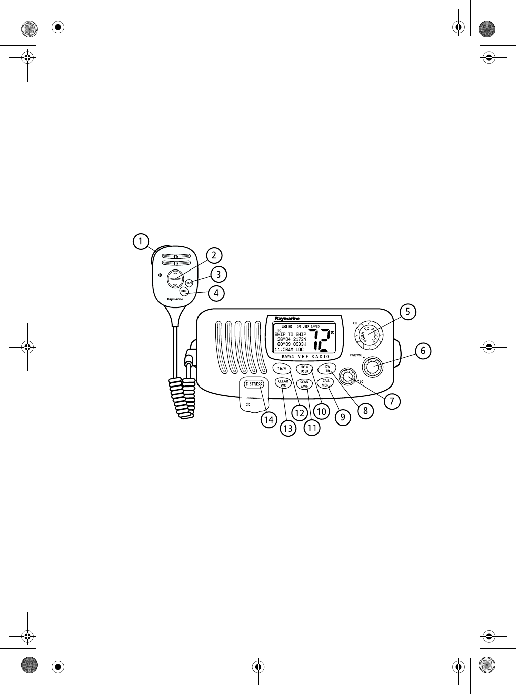
3.1 Keypad and Rotary Knobs ............................................................. 11
Handset Keys .............................................................................. 12
Base Station Rotary Keys ........................................................... 12
Base Station Push Keys .............................................................. 12
Handset ....................................................................................... 13
1. PTT .................................................................................... 13
2. UP/DOWN ........................................................................ 13
3. 16/9 ................................................................................... 13
4. HILO ................................................................................. 13
Base Station ................................................................................ 13
5. CH ..................................................................................... 13
6. PWR/VOL ........................................................................ 13
7. SQ ..................................................................................... 13
8. DW/TRI ............................................................................ 13
9. CALL/MENU ................................................................... 14
10. HILO/USER ................................................................... 15
81231_1.book Page vii Thursday, April 22, 2004 5:21 PM

viii Ray54 VHF Radio
11. SCAN / SAVE ................................................................. 15
12. 16/9 ..................................................................................16
13. CLEAR/WX ................................................................... 16
14. DISTRESS ......................................................................16
3.2 LCD Display .................................................................................. 17
1. (HI/LO) TX Power .................................................................. 17
2. (TX) Transmitting ................................................................... 17
3. (RX) Receiving ....................................................................... 17
4. (LOCAL) Local/Distant Mode ............................................... 17
5. DSC Message ......................................................................... 17
6. NO GPS ................................................................................... 18
7. Battery Low ............................................................................ 18
8 (USER) Favorite Channel Mode .............................................. 18
9. (SAVED) Memory Mode ........................................................ 18
10. (WX) Weather Channel ......................................................... 18
11. (ALERT) Weather Alert ........................................................ 18
12. (U I C) Channel Set ............................................................... 18
13. (A) Simplex Channel ............................................................ 18
14. (B) Receive-only Channel .................................................... 18
15. Channel Number ...................................................................18
16. Dot Matrix Display ............................................................... 18
Chapter 4: General Operations .........................................................................19
4.1 Turning the Power ON and OFF ..................................................... 19
4.2 Setting the Volume ......................................................................... 19
4.3 Setting the Squelch ......................................................................... 20
4.4 Setting the Power Output ................................................................ 20
Overriding the Low Output Power Restriction ...........................21
4.5 Setting the Channel ........................................................................ 21
On the handset... .................................................................... 21
On the base station... ............................................................. 21
4.6 Selecting a Weather Channel .......................................................... 22
Weather Alert Operation ....................................................... 23
4.7 Selecting the Priority Channel ........................................................ 24
4.8 Selecting the Secondary Priority Channel ...................................... 25
Reprograming the Secondary Priority Channel .......................... 25
4.9 Transmitting ................................................................................... 27
4.10 Using the Scan Modes .................................................................... 27
All Scan ....................................................................................... 28
Saved (Memory) Scan ................................................................ 29
Priority All Scan ......................................................................... 30
Priority Saved Scan ..................................................................... 31
81231_1.book Page viii Thursday, April 22, 2004 5:21 PM

ix
4.11 Adding Channels to Memory ......................................................... 32
4.12 Using the Monitor Modes ............................................................... 33
Dual Watch ................................................................................. 33
Tri Watch ..................................................................................... 34
4.13 USER Channel Mode ..................................................................... 35
4.14 DSC Call Operation ....................................................................... 35
4.15 Menu Mode Operation ................................................................... 36
Chapter 5: Digital Select Calling (DSC) ............................................................37
5.1 DSC Call Function ......................................................................... 38
5.2 Individual Calls .............................................................................. 39
Making Calls to Coast Stations ................................................... 39
Transmitting an Individual Call Using the Phonebook ............... 40
Manually Sending an Individual Call ......................................... 42
Receiving Individual Calls ......................................................... 45
5.3 Group Calls .................................................................................... 46
Transmitting a Group Call .......................................................... 46
Receiving Group Calls ................................................................ 48
5.4 All Ships Calls ................................................................................ 50
Transmitting an All Ships Safety Call ......................................... 50
Transmitting an All Ships Urgency Call ..................................... 52
Receiving an All Ships Call ........................................................ 53
5.5 Distress Calls .................................................................................. 55
Sending an Undesignated (QUICK) Distress Call ..................... 56
Sending a Designated Distress Call ............................................ 58
Cancelling a Distress Call Made in Error .................................... 60
Receiving a Distress Call ............................................................ 60
Receiving a Distress ACK Sent from a Coast Station ................. 61
Receiving a Distress Relay Sent by Another Vessel ................... 61
5.6 Position Request ............................................................................. 62
Specifying the Target Vessel from the Phonebook ..................... 62
Retrieving the Last Received Position Data ............................... 64
Manually Sending a Position Request ........................................ 64
5.7 Call Log .......................................................................................... 67
Making a Call from a Call Log Entry .......................................... 68
Saving an MMSI ID Number from a Call Log Entry .................. 69
5.8 DSC Distress Log ........................................................................... 70
Chapter 6: Menu Settings ..................................................................................73
6.1 Menu Function ............................................................................... 73
6.2 DSC Phonebook ............................................................................. 75
Adding an Entry .......................................................................... 75
Editing an Existing Entry ............................................................ 77
Deleting an Existing Entry .......................................................... 78
81231_1.book Page ix Thursday, April 22, 2004 5:21 PM

x Ray54 VHF Radio
6.3 Local / Distant ................................................................................78
6.4 Backlight Adjustment .................................................................... 80
6.5 Contrast Adjustment .......................................................................81
6.6 GPS/Time Setup .............................................................................82
When GPS Information Not Available ................................. 82
6.7 Settings ........................................................................................... 86
Latitude/Longitude Display ........................................................ 88
Time Display ............................................................................... 89
Time Offset ................................................................................. 90
Time Format ................................................................................ 91
COG/SOG Display .....................................................................92
6.8 Radio Setup .................................................................................... 93
Frequency Band ..........................................................................94
Displaying the Channel Name .................................................... 95
Editing a Channel Name Entry ............................................. 96
Deleting a Channel Name Entry ...........................................97
Ring Volume ............................................................................... 99
Key Beep ...................................................................................100
6.9 DSC Setup .................................................................................... 101
My MMSI ID ............................................................................102
Group MMSI Setup .................................................................. 104
Adding a New Group .......................................................... 104
Editing an Existing Entry ....................................................106
Position Reply ........................................................................... 108
Automatic Channel Changing of DSC Calls ............................ 109
Procedure When Enabled ...................................................109
Procedure When Disabled .................................................. 109
6.10 Resetting Factory Defaults ........................................................... 111
Appendix A:Specifications ...............................................................................113
Appendix B:Channel List ...................................................................................115
U.S. VHF Marine Radio Channels and Frequencies ................ 115
Canadian VHF Marine Radio Channels and Frequencies........ 118
International VHF Marine Radio Channels & Frequencies ..... 123
WX Channels (North America only) ........................................ 126
Appendix C:Glossary .........................................................................................127
Index ................................................................................................129
81231_1.book Page x Thursday, April 22, 2004 5:21 PM
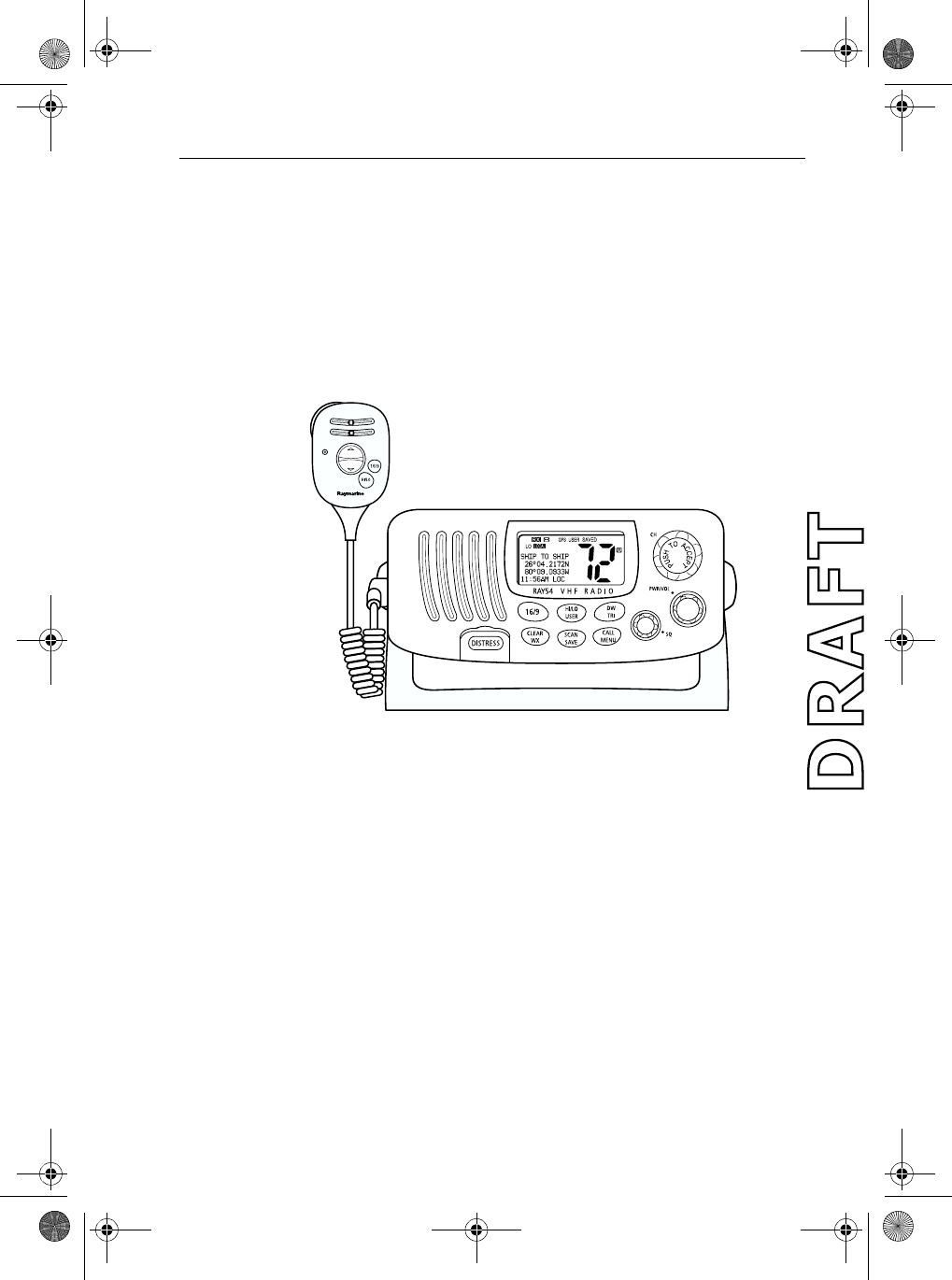
Chapter 1: Introduction 1
Chapter 1: Introduction
1.1 Ray54 Fixed Station VHF Radio
The Ray54 marine VHF radiotelephone is a microprocessor-controlled
transceiver that provides reliable simplex (single frequency) and semi-
duplex (two frequency) communications. This handbook describes the
physical and functional characteristics of the radio.
Figure 1-1: Ray54VHF Radio
The Ray54 provides two-way communications on all US, Canadian and
International marine channels and ten weather channels. Refer to the
Frequency Tables in Appendix B, which list all marine VHF channels
available in your radio. You should familiarize yourself with these tables to
ensure proper channel usage.
1.2 Features
The Ray54 is designed and manufactured to provide ease of operation with
excellent reliability. The Ray54 features:
•All Scan, Saved-channels Scan, and Priority Scan features
•Dual/Tri Watch Monitor modes
•10 Weather Channels
•Dedicated key for switching to Priority Channel 16
81231_1.book Page 1 Thursday, April 22, 2004 5:21 PM

2 Ray54 VHF Radio
•Programmable Secondary Priority Channel key
•Waterproof to IPX-7 standard
•Large 2" x 1.5" LCD with 4 x 12 Dot Matrix Display
•Adjustable Backlight Control
•All USA, Canada and International Channels
•10 Weather Channels with 1050Hz Alert Tone Detect
•GPS Input for Automatic Time and Position Update
•Channel Naming with Phonebook
Digital Selective Calling (DSC)
The Digital Selective Calling (DSC) protocol is a globally applied system
used to send and receive digital calls. DSC uses a unique Maritime Mobile
Service Identity (MMSI) number to direct DSC calls directly to your radio,
much like a telephone number.When the DSC signal is received, the radio
quickly switches over to Channel 70 and performs the corresponding
operation.
Note: An MMSI number is required to operate the DSC equipment in this ra-
dio. You can program the MMSI number yourself one time only using the
Menu Operation described in this handbook. Otherwise, your Raymarine
dealer can program or change the number for you.
When a DSC call is received, the Ray54 Base Station automatically responds
based on the type of call. When receiving a DSC call from another vessel or a
coast station, an alert sounds and DSC data appears in the LCD – such as time
of a call, the caller and the type and priority of a call.
DSC functions are described in Chapter 5:
81231_1.book Page 2 Thursday, April 22, 2004 5:21 PM

Chapter 2: Installation 3
Chapter 2: Installation
2.1 Unpacking and Inspection
Use care when unpacking the unit from the shipping carton to prevent
damage to the contents. It is also good practice to save the carton and the
interior packing material in the event you must return the unit to the factory.
Equipment Supplied
The following is a list of materials supplied with the Ray54:
The following is a list of optional equipment for the Ray54:
Table 2-1: Supplied Components
Part Number Description
E43022
E43023
Ray54, White
Ray54, Charcoal Gray
81231 Handbook, Ray54
R49108
R49128
R49133
Power Cord, Ray54
NMEA Cable, Ray54
Speaker Cord, Ray54
R49093
R49095
Mounting Yoke for White Ray54
Mounting Yoke for Charcoal Ray54
R49094
R49096
Yoke Knob and Spacer for White Ray54
Yoke Knob and Spacer for Charcoal Ray54
R49104
R49105
Microphone Bracket for White Ray54
Microphone Bracket for Charcoal Ray54
R49109
R49110
Sun Cover, White
Sun Cover, Charcoal Gray
Table 2-2: Optional Equipment
Part Number Description
E46034 Flush Mount Kit, A Series VHF Radios
81231_1.book Page 3 Thursday, April 22, 2004 5:21 PM

4 Ray54 VHF Radio
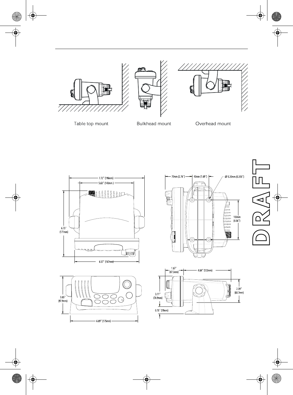
2.2 Planning the Installation
When planning the installation of your Ray54, consider the following
conditions to ensure dependable and trouble-free operation.
The Base Station Transceiver should be located in the room from which the
ship is normally navigated.
The Base Station Transceiver is designed to be mounted horizontally or
vertically on a flat bulkhead. Select a location that is non-metallic, dry,
protected, well-ventilated, and free from high operating temperatures and
excessive vibration. Provide sufficient space behind the transceiver to allow
for proper cable connections to the rear panel connectors. Locate the
transceiver as near as possible to the power source yet as far apart as possible
from any devices that may cause interference such as motors, generators, and
other on board electronics. The transceiver should be protected from
prolonged direct exposure to rain and salt spray.
The transceiver is NOT designed to be mounted in engine compartments. Do
NOT install the transceiver in a location where there may be flammable
vapors (such as in an engine room or compartment, or in a fuel tank bay),
water splash or spray from bilges or hatches, where it is at risk from physical
damage from heavy items (such as hatch covers, tool boxes, etc.), or where it
might be covered by other equipment. Locate the Base Station Transceiver
and Handset at least 1 meter from the antenna.
Safe Compass Distance is 1 meter for a common mechanical compass; other
compass types may require greater distances. To be sure, you should locate
the radio as far as possible from the compass. Test your compass to verify
proper operation while the radio is also operating.
Mount the base station transceiver to allow easy access from the location
where the ship is normally navigated.
Typical Mounting Methods
The Ray54 can be conveniently mounted on a chart table, bulkhead,
overhead, or any other desired location. Refer to the following figure for
typical mounting methods.
81231_1.book Page 4 Thursday, April 22, 2004 5:21 PM
Chapter 2: Installation 5
Figure 2-1: Typical Mounting Methods
CAUTION: Make sure there are no hidden electrical wires or other items
behind the desired location before proceeding. Check that free access for
mounting and cabling is available.
Figure 2-2: Mounting Dimensions
81231_1.book Page 5 Thursday, April 22, 2004 5:21 PM

6 Ray54 VHF Radio
Flush Mounting
In addition to the typical Mounting Methods, theRay54 may also be flush
mounted using the optional E46034 Flush Mount Kit. Instructions for
installing the radio using the Flush Mount Kit are included with the kit. These
kits are available from your Raymarine dealer.
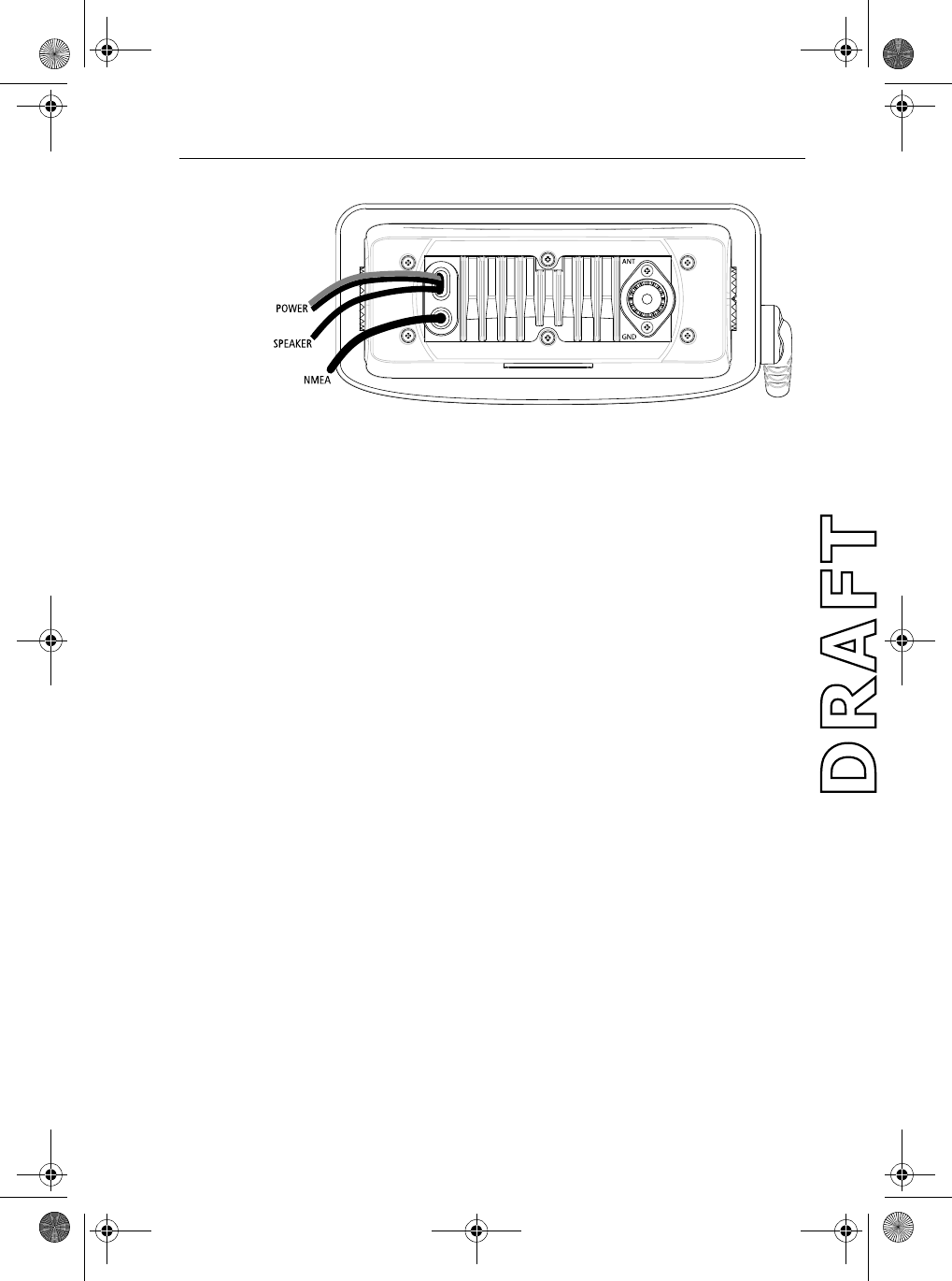
2.3 Power Connections
The red and black power cord provides connections to DC power. The red (+)
wire is connected to the positive terminal of the power source and contains a
7 amp in-line fuse. The black (-) wire is connected to the negative (ground) of
the power source. Should the power connections be inadvertently reversed,
the unit will not power up but no damage will occur. Check the polarity with
a VOM (Voltage/Ohm Meter) and reconnect observing correct polarity. If the
fuse ever needs replacement, be sure to use the same type and rating.
In most cases the length of the power cord should be adequate enough to
reach the DC power source. If additional wire length is required, the cable
can be extended by adding more cable as necessary. However, for power
cable runs longer than 15 feet, larger wire diameter size should be used to
prevent voltage line loss.
Your Ray54 should be connected to the nearest primary source of ship's DC
power. A typical source may be a circuit breaker on the power panel or a fuse
block near the unit. When connecting to either of these sources, the circuit
breaker or other in-line fuse should be rated at 10 amps.
It is recommended that lugs be used to connect the power cable to the DC
supply and the lug connections should be both crimped and soldered. This is
very important in order to ensure adequate current draw to the equipment.
Intermittent operation may result if an insufficient connection is made to the
power source. The connection terminal should be clean, with no sign of
corrosion.
81231_1.book Page 6 Thursday, April 22, 2004 5:21 PM
Chapter 2: Installation 7
Figure 2-3: Wiring Connections
2.4 External Speaker Connections
Located just below the power cord is a cable for connection to an optional
external speaker.
Connect the white(+) wire and black (–) wire to the speaker observing
polarity as it is marked on the speaker. When connected, the external speaker
will function simultaneously with the internal speaker.
CAUTION:
DO NOT short the white (+) wire to the black (–) wire. DO NOT short
the black (–) Speaker wire to the black Power (–) wire.
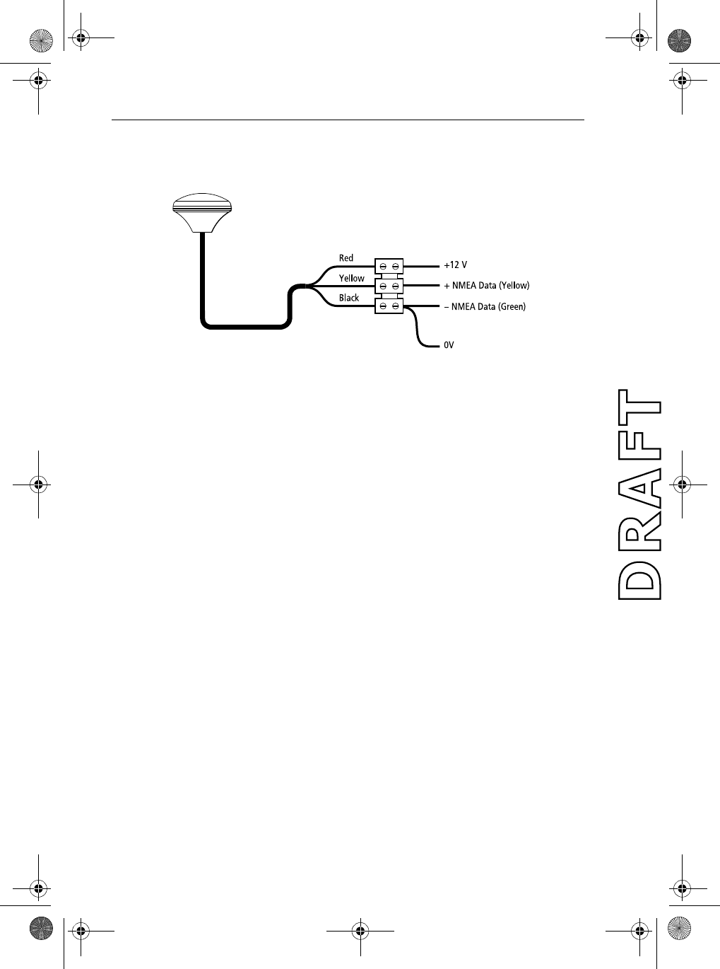
2.5 NMEA Data
Inputting NMEA data will provide position information to the radio. The
Ray54 accepts NMEA 0183 data from a position determining device (GPS,
etc.) to provide the Latitude and Longitude position information that is
transmitted during a DSC Distress Call.
When valid NMEA signal is detected, the GPS indicator appears on the
LCD.When no valid NMEA signal is detected, the NO GPS indicator appears.
Connect the input(s) of the positioning device to the Yellow (NMEA+) and
Green (NMEA–) wires in the NMEA cable.
An example of how to connect the NMEA cables and power supply using a
suitable connector block is shown in the diagram below. For specific
instructions how to connect your particular GPS, please refer to the
handbook that came with that device.
81231_1.book Page 7 Thursday, April 22, 2004 5:21 PM
8 Ray54 VHF Radio
Note: For non-differential GPS, all return connections (-) must be tied to a
common ground reference.
Figure 2-4: GPS Wiring
2.6 Antenna Connections
The coaxial VHF antenna cable connects to the Ray54 antenna cable on the
rear panel using a PL259 VHF type connector. The antenna cable length can
be critical to performance. If you are uncertain, contact a professional
installer or call Raymarine Product Support. If a longer cable length is
required, RG-58 (50 ohm) coaxial cable or equivalent cable can be used for
runs up to a maximum of 50 feet. If the distance required is even greater,
Raymarine recommends using low loss RG-213 or equivalent cable for the
entire run to avoid excessive losses in power output
If the antenna RF connector is likely to be exposed to the marine
environment, a protective coating of grease (Dow Corning DC-4 or similar)
can be applied to the connector before connecting it to the radio. Any other
extensions or adapters in the cable run should also be protected by silicon
grease and then wrapped with a waterproofing tape.
Antenna Mounting Suggestions
The best radio in the world is useless without a quality antenna and good
location. Mounting the VHF antenna properly is very important because it
will directly affect the performance of your VHF radio. A VHF antenna
designed for marine vessels should be used.
•Since VHF transmission is essentially line-of-sight, mount the antenna at
a location on the vessel that is free of obstruction to obtain maximum
range.
81231_1.book Page 8 Thursday, April 22, 2004 5:21 PM

Chapter 2: Installation 9
•If you must extend the length of the coaxial cable between the antenna
and the radio, use a coaxial cable designed for the least amount of power
loss over the entire cable length.
Antenna Mounting and EME Exposure
For optimal radio performance and minimal human exposure to radio
frequency electromagnetic energy, make sure the antenna is:
•connected to the radio before transmitting
•properly mounted
•located where it will be away from people
•located at least three feet (91 cm) from the base station transceiver
2.7 Grounding
While special grounding is not generally required for VHF radiotelephone
installations, it is good marine practice to properly ground all electronic
equipment to the ship's earth ground system. The Ray54 can be connected to
ground by attaching a wire to the screw labelled GND on the unit's rear panel
just below the antenna connection. Then attach the other end of the wire to
the nearest ship's earth ground connection point. The recommended wire to
be used for such grounding is #10 AWG.
81231_1.book Page 9 Thursday, April 22, 2004 5:21 PM

10 Ray54 VHF Radio
81231_1.book Page 10 Thursday, April 22, 2004 5:21 PM
Chapter 3: Getting Started 11
Chapter 3: Getting Started
3.1 Keypad and Rotary Knobs
Several of the keys on the front panel of the base station serve multiple
purposes. For the most part, the function indicated on the first line of the key
is accessed by pressing and releasing that key. The function indicated on the
second line of the key is accessed by pressing and holding the key for three
seconds.
Figure 3-1: Ray54 Keys Layout
81231_1.book Page 11 Thursday, April 22, 2004 5:21 PM

12 Ray54 VHF Radio
Handset Keys
Base Station Rotary Keys
Base Station Push Keys
Key Name Press & Release (<3 sec.) Press & Hold (>3 sec.)
1. PTT Push-to-Talk Push-to-Talk
2. UP/DOWN Channel increment/decrement Rapid channel change
3. 16/9 Switches between the Priority
and Working Channels
Switches to Secondary Priority CH (9);
If already tuned to secondary channel,
programs a new secondary Priority Chan-
nel.
4. HI/LO TX Power High/Low TX Power High/Low
Key Name Function
5. CH/PUSH Channel increment/decrement and programming ENTER key
6. PWR/VOL Power radio ON / OFF and adjust volume level
7. SQ Adjust squelch threshold level
Key Name Press & Release (<3 sec.) Press & Hold (>3 sec.)
8. DW/TRI Dual Watch Mode Tri Watch Mode
9. CALL/MENU Activate DSC functions Activate Menu functions
10. HL/USER TX Power High/Low USER (Saved Memory Channel) Mode
11. SCAN/SAVE Scan ON/OFF SAVE/DELETE channel to/from memory
12.16/9 Switches between the Priority
and Working Channels
Switches to secondary Priority CH (9);
If already tuned to secondary channel,
programs a new secondary Priority Chan-
nel.
13. CLEAR/WX Cancel function Weather Channel Mode
14. DISTRESS (under door) Activate Distress Make Distress Call
81231_1.book Page 12 Thursday, April 22, 2004 5:21 PM
Chapter 3: Getting Started 13
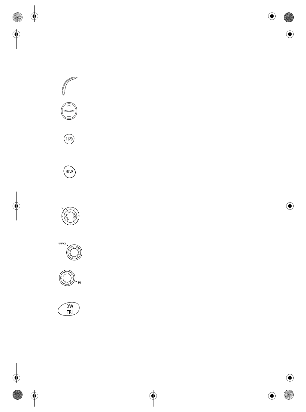
Handset
1. PTT
Press this Push-to-Talk key to transmit.
2. UP/DOWN
Use the arrow keys to change the active channel number. Press and hold for
rapid channel changing.
3. 16/9
Use this key to switch to the priority channel or to change the value of the
Secondary Priority Channel.
4. HILO
Use this key to toggle the transmit power from HIGH to LOW.
Base Station
5. CH
Rotate this knob to change the current channel number and to change values
in Menu mode or during programming. Press the knob to enter values
selected in Menu mode or during programming.
6. PWR/VOL
Use this knob to turn the radio ON and OFF and to set the volume.
7. SQ
Use this knob to set the squelch threshold, which cuts off the receiver when
the signal is too weak for reception of anything but noise.
8. DW/TRI
Press and release this key to select Dual Watch mode, which monitors the
current working channel and CH 16 in cycle. Press and hold to select Tri
Watch, which monitors CH 16, the current working channel and the channel
you have set as the Secondary Priority Channel in cycle. See Section 4.12.
81231_1.book Page 13 Thursday, April 22, 2004 5:21 PM
14 Ray54 VHF Radio
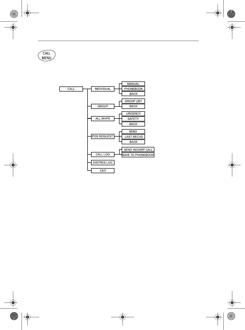
9. CALL/MENU
Press and release this key to select to enter DSC Call Mode, which is used for
making DSC Calls and viewing the Call Logs and the calling Phonebook.
DSC Call menu structure is outlined here. It is detailed in Chapter 5:
81231_1.book Page 14 Thursday, April 22, 2004 5:21 PM
Chapter 3: Getting Started 15
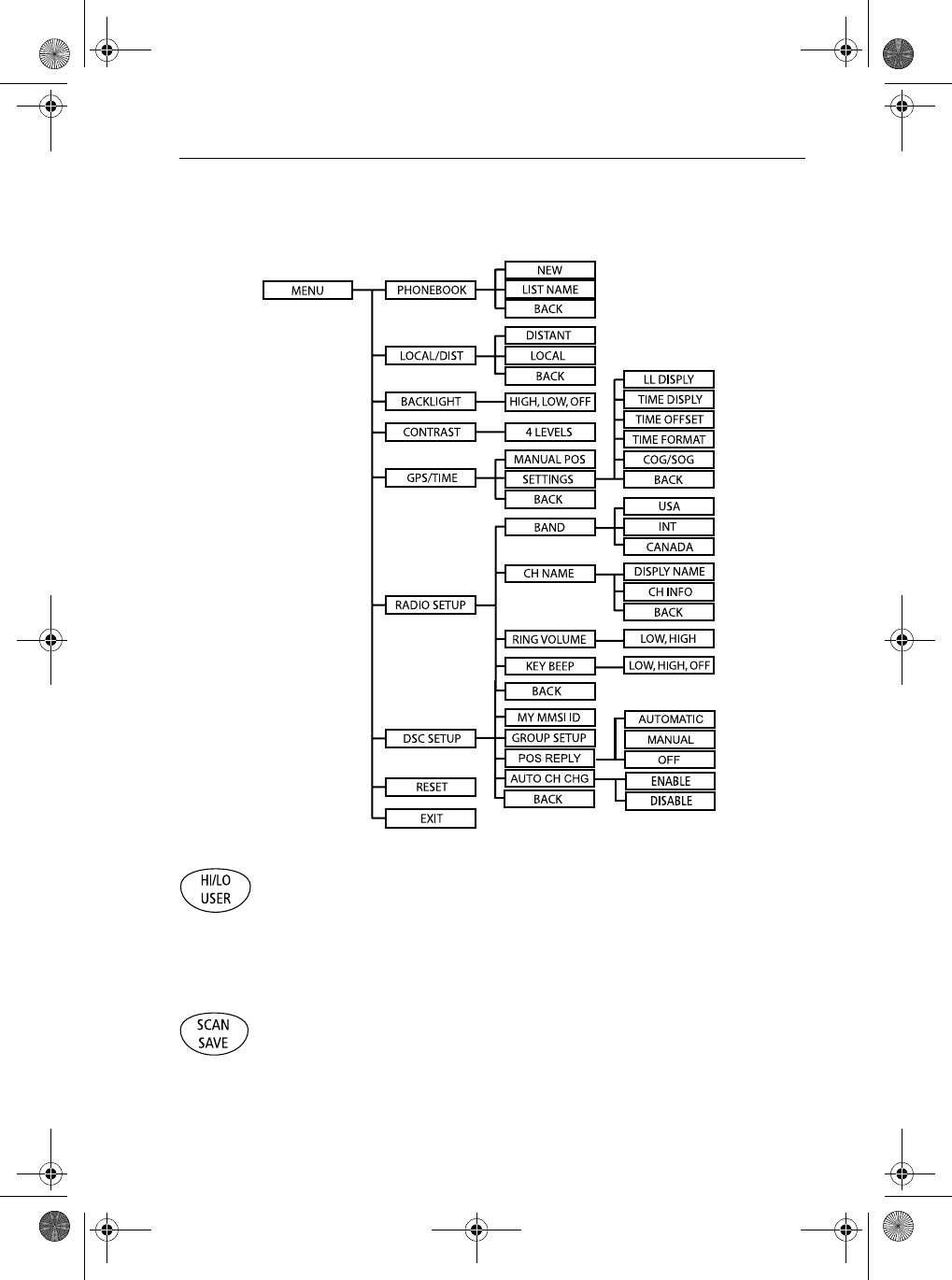
Press and hold this key to select Menu Mode, which is used to setup the radio.
The menu structure is outlined here. It is fully described in Chapter 6:
10. HILO/USER
Press and release this key to toggle the transmit power from HIGH to LOW.
Press and hold to select User Channel Mode, which displays only the
channels that you have saved to memory. User Mode is described in Section
4.13.
11. SCAN / SAVE
Press and release this key to enter one of the Scan Modes, which are
described in Section 4.10. Press and hold to enter a channel into the radio’s
memory. This function is described in Section 4.11.
81231_1.book Page 15 Thursday, April 22, 2004 5:21 PM
16 Ray54 VHF Radio
12. 16/9
Use this key to switch to the priority channel or to change the value of the
Secondary Priority Channel.
13. CLEAR/WX
Press and release to terminate a function and return to the last-used channel.
Press and hold to select the Weather mode.
14. DISTRESS
Push down the spring-loaded cover and press this key to make a DSC
Distress Call. Instructions for making a Distress Call are described in Section
5.5.
81231_1.book Page 16 Thursday, April 22, 2004 5:21 PM
Chapter 3: Getting Started 17
3.2 LCD Display
The following describes the functional characters on the Ray54’s LCD.
Figure 3-2: Ray54 LCD Layout
1. (HI/LO) TX Power
Indicates whether transmit power is set for 25 watts (HI) or 1 watt (LO).
2. (TX) Transmitting
Indicates the PTT is being pressed and the radio is transmitting.
3. (RX) Receiving
Indicates that the radio is receiving a radio signal.
4. (LOCAL) Local/Distant Mode
Indicates the radio is in Local Reception mode, which decreases receiver
sensitivity in high traffic areas to decrease unwanted reception.
5. DSC Message
Indicates the radio has received a DSC call. Details of the call can be viewed
in the DSC log. See Section 5.8.
81231_1.book Page 17 Thursday, April 22, 2004 5:21 PM

18 Ray54 VHF Radio
6. NO GPS
When GPS appears, positional data is available. When NO GPS appears, the
radio is not receiving positional data.
7. Battery Low
Indicates vessel battery voltage is low.
8 (USER) Favorite Channel Mode
Indicates the radio is in USER Mode. USER Mode displays only the
channels that you have saved to memory, enabling you to easily scan your
favorite channels while bypassing unwanted or seldom-used channels.
9. (SAVED) Memory Mode
Indicates the current channel has been saved in memory. Appears during
Saved Scan mode. Only saved channels are scanned during USER mode.
10. (WX) Weather Channel
Weather channel mode is active. US and Canada only.
11. (ALERT) Weather Alert
A weather alert is being received. US and Canada only.
12. (U I C) Channel Set
Indicates which channel set is selected: US, International or Canadian.
13. (A) Simplex Channel
Indicates that the currently-selected channel is simplex; you transmit and
receive on the same frequency.
14. (B) Receive-only Channel
Indicates that you cannot transmit on the currently-selected channel; it is
receive-only. Used with Canadian channels only.
15. Channel Number
Displays the current channel number.
16. Dot Matrix Display
Indicates special conditions or radio functions.
81231_1.book Page 18 Thursday, April 22, 2004 5:21 PM
Chapter 4: General Operations 19
Chapter 4: General Operations
4.1 Turning the Power ON and OFF
Turn the PWR/VOL knob clockwise until it clicks.
When the unit powers up in Normal mode it:
1. Beeps, illuminates the backlight at full brightness, and displays all seg-
ments and indicators for 2 seconds.
2. Displays RAYMARINE and the software version number on the dot matrix
display.
3. Recalls the last CH number, TX power settings and operation mode.
If no last-used setting data exists, goes to CH 16 and high TX Power.
When GPS Data is available, extended position data is also displayed with
the offset time on the dot matrix display. This information will be displayed
when display option for the position and time is enabled on the Menu. See
Section 6.6.
➤To turn the unit OFF:
Rotate the Volume knob completely counterclockwise until it clicks.
4.2 Setting the Volume
Adjust the PWR/VOL knob to control the loudspeaker volume level. Turn
clockwise to increase the volume; counterclockwise to decrease the volume.
Note: Key press beep volume is also controlled by the VOL level.
81231_1.book Page 19 Thursday, April 22, 2004 5:21 PM
20 Ray54 VHF Radio
4.3 Setting the Squelch
The Squelch circuit sets the threshold for cutting off the receiver when the
signal is too weak for reception of anything but noise.
To properly set the squelch, rotate the SQ knob counterclockwise until audio
is heard. Then rotate clockwise until background noise disappears.
4.4 Setting the Power Output
The choice of power output is dependent upon the distance of transmission
and transmitting conditions.
Press and release the HL/USER key on the base station or handset to toggle
the TX power from LOW (1 watt) to HIGH (25 watts). The corresponding LO
or HI indicator appears on the LCD.
Initial contact should always be attempted using low power. You should
switch to high power only when contact can not be made on low power in
emergency situations. This procedure is specified by the FCC but is also part
of marine communications courtesy.
81231_1.book Page 20 Thursday, April 22, 2004 5:21 PM
Chapter 4: General Operations 21
Note: Some channels are limited by regulation to be low power only. If the
HILO operation request is denied, an error tone beeps.
Overriding the Low Output Power Restriction
In the US, channels 13 and 67 can temporarily
override the low power restriction.
➤To override the LO power restriction on
channels 13 or 67 and transmit at high power:
Press and hold the PTT key on the handset as
you press and hold the HI/LO key. The TX power
is set to HI power for as long as you hold down
the HI/LO key.
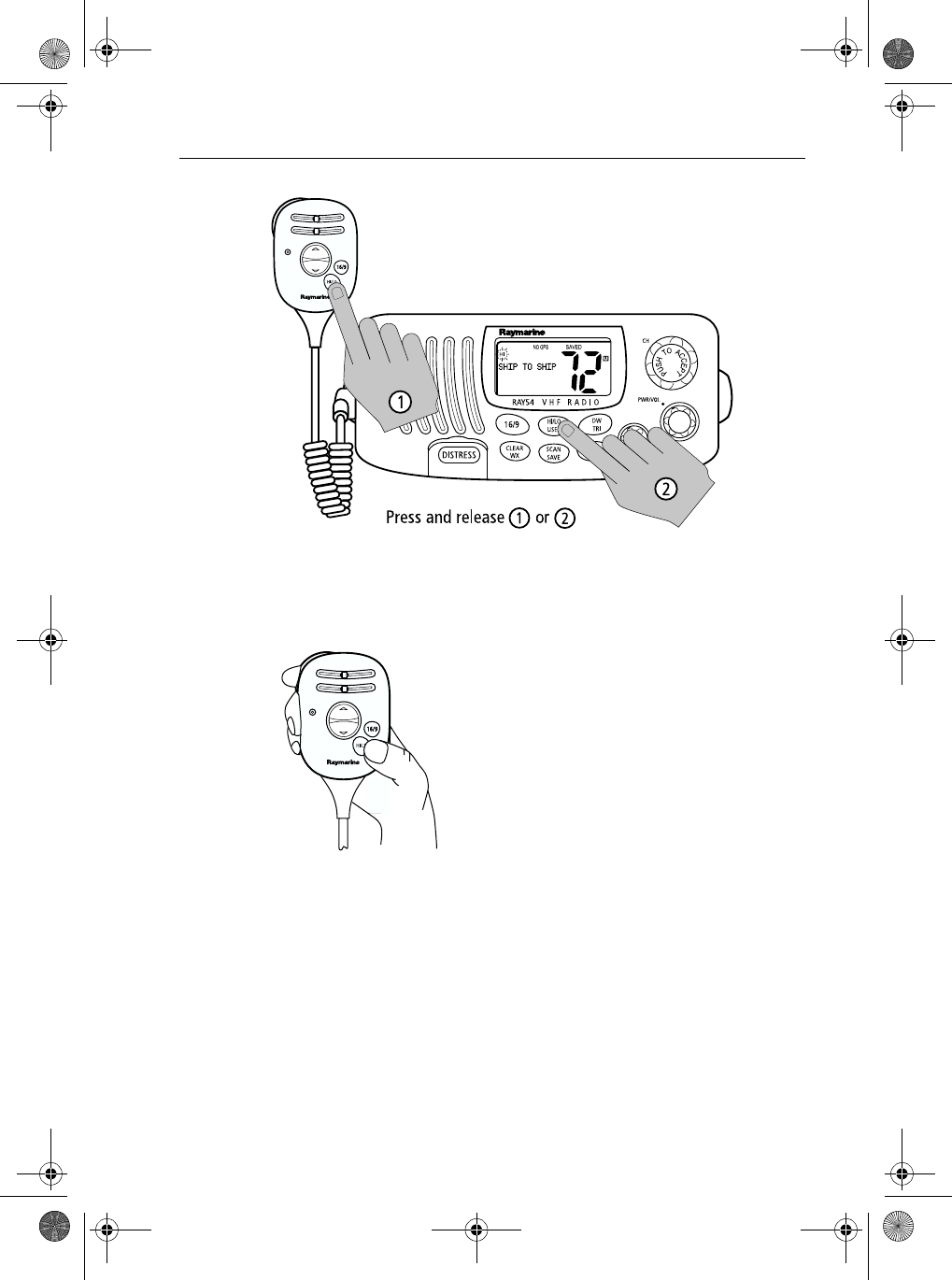
4.5Setting the Channel
On the handset...
Press and release the UP arrow to increment the channel number.
Press and release the DOWN arrow to decrement the channel.
Press and hold either key for rapid channel scrolling.
On the base station...
Rotate the CH knob clockwise to increment the channel number.
81231_1.book Page 21 Thursday, April 22, 2004 5:21 PM
22 Ray54 VHF Radio
Rotate the CH knob counterclockwise to decrement the channel number.
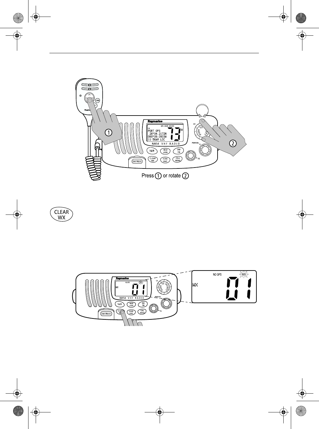
4.6 Selecting a Weather Channel
The US National Oceanic and Atmospheric Administration (NOAA)
broadcasts continuous weather reports and severe weather alerts, as needed.
The Ray54 is programmed to receive 10 NOAA weather channels and sound
an alarm if a weather alert is received.
Press and hold the CLEAR/WX key to enter Weather mode. The WX
indicator appears on the LCD.
Rotate the CH knob to change the WX channels 1 through Channel 10.
Press and hold the CLEAR/WX key again to return to normal operation.
Note:
1. WX broadcasts can only be heard in the US and Canada.
2. When Dual or Tri Watch is activate in the WX mode, the watch monitors
the current WX channel and Priority channel(s).
81231_1.book Page 22 Thursday, April 22, 2004 5:21 PM
Chapter 4: General Operations 23
3. During Weather mode, the PTT, SCAN/SAVE, and HILO/USER keys are
disabled and an error beep sounds if pressed.
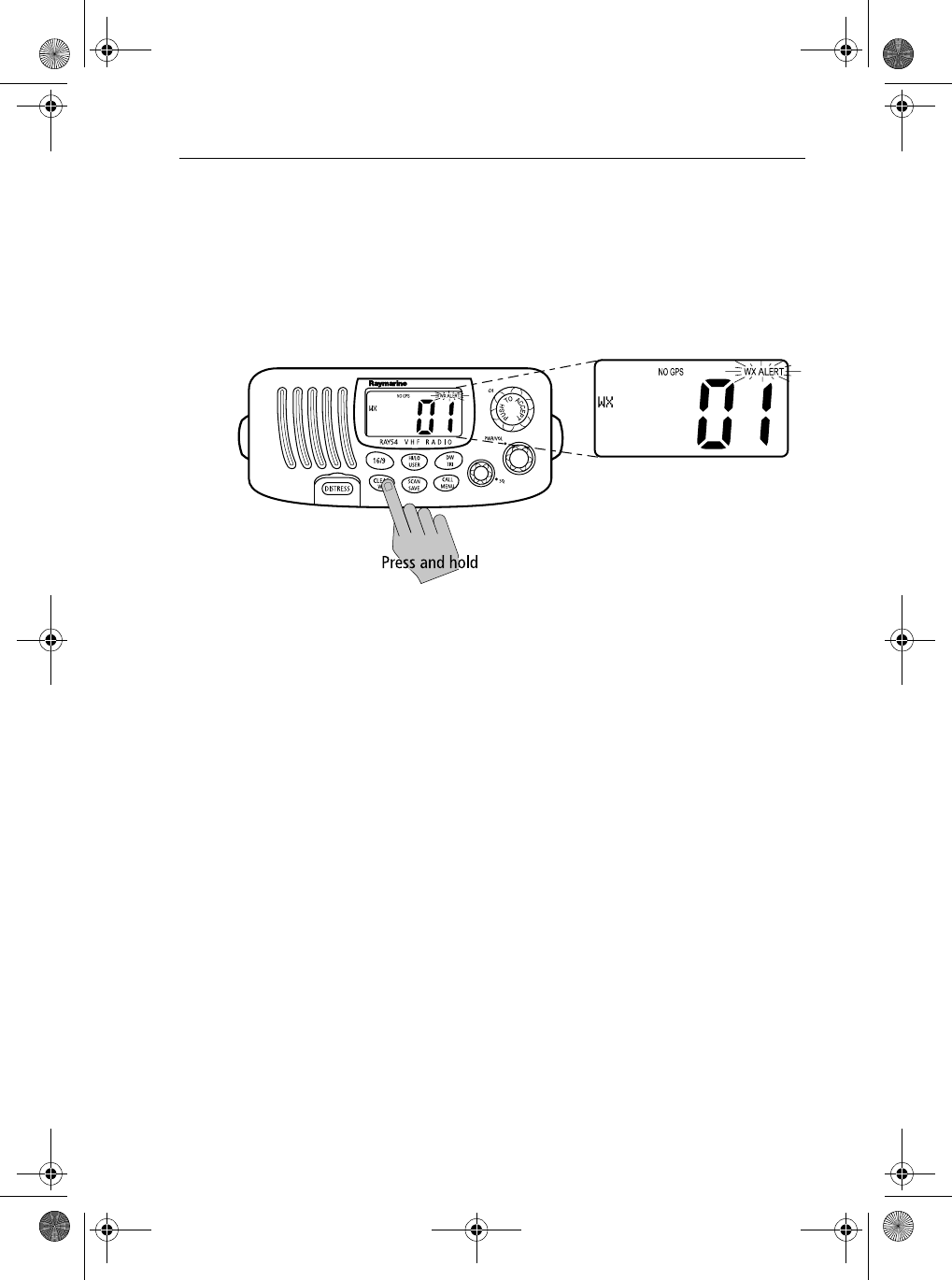
Weather Alert Operation
Weather Alert is toggled ON and OFF by pressing and holding CLEAR/WX
key in the weather mode. The ALERT indicator illuminates.
When Weather Alert function is enabled and the radio is tuned to the normal
working channel, the last-used weather channel is checked every four
minutes for weather alert tone. If the alert tone is detected, the WX and ALERT
indicators flash and a short alarm tone sounds.
The radio automatically turns to the currently-monitored WX channel where
the weather alert has been detected. The alert is detected in all modes of
operation (Standby, Dual and Tri Watch, Scan, etc.)
81231_1.book Page 23 Thursday, April 22, 2004 5:21 PM
24 Ray54 VHF Radio
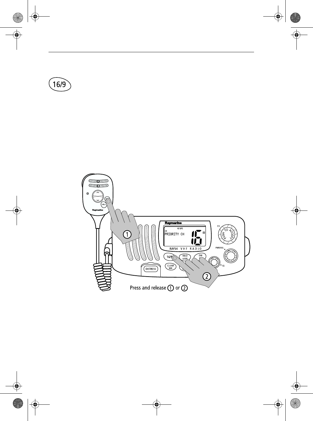
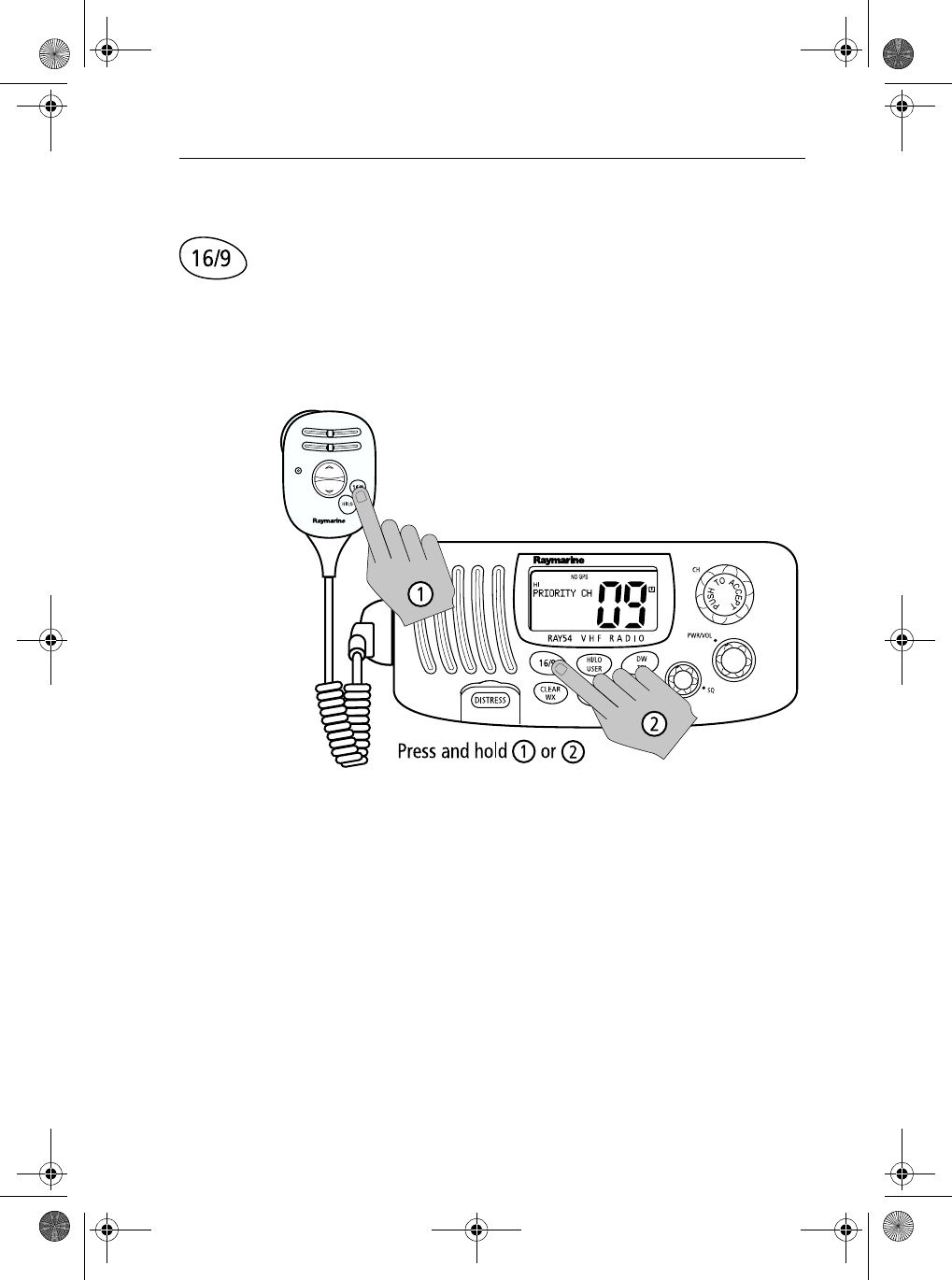
4.7 Selecting the Priority Channel
The Ray54E provides you with a dedicated key for switching to the Priority
Channel 16.
If not already tuned to the Priority Channel 16, press and release the 16/9
key to switch to CH16 at high power.
PRIORITY CH appears in the dot matrix display.
If already on CH 16, press and release the 16/9 to return to the last-used
working channel.
Note: When the priority channel is selected, it is always set to HIGH trans-
mit power. You may reduce power if desired by pressing the HI/LO key.
The 16/9 key also can be used to cancel all modes and switch to CH 16.
Note: When you press the 16/9 key, the radio always switches to HIGH pow-
er. You can use the HL/USER key to change to LOW power.
81231_1.book Page 24 Thursday, April 22, 2004 5:21 PM
Chapter 4: General Operations 25
4.8 Selecting the Secondary Priority Channel
The Ray54E enables you to program the 16/9 key to store a Secondary
Priority Channel. The default is CH 9.
If on a working channel, press and hold the 16/9 for greater than 3 seconds
to switch to the Secondary Priority Channel at high power. The default is CH
9.
PRIORITY CH appears in the dot matrix display.
If on primary Priority CH16, press and hold the 16/9for greater 3 seconds to
switch to the Secondary Priority Channel at HI power. The default is CH 9.If
already on the Secondary Priority Channel, press and release the 16/9 key to
switch to Priority Channel 16 at high power.
Reprograming the Secondary Priority Channel
1. Switch to the Secondary Priority Channel.
2. Press and hold the 16/9 key for greater 3 seconds to switch to Repro-
gram mode. An alert tone sounds and the current Secondary Priority
Channel flashes.
3. Change the channel number with the CH key.
81231_1.book Page 25 Thursday, April 22, 2004 5:21 PM
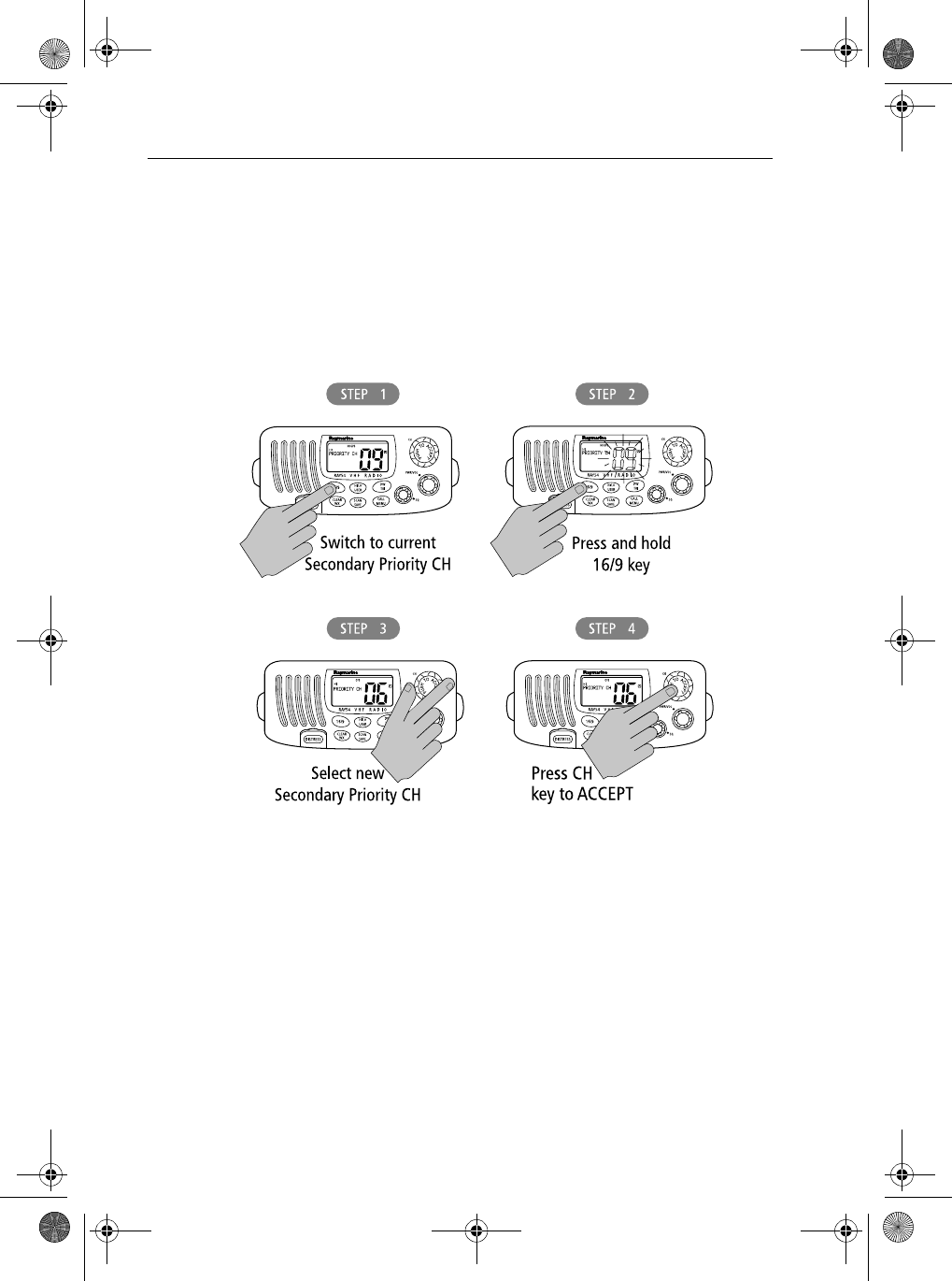
26 Ray54 VHF Radio
4. Push the CH key to ACCEPT the new Secondary Priority selection. An
alert tone sounds to indicate that the Secondary Priority Channel has been
changed.
Press and release the CLEAR/WX key to terminate the programming and
return to the last-used channel.
Note: During the reprogramming of the Secondary Priority Channel, the
PTT, WX and DW/TRI keys are disabled and sound error beep if pressed.
81231_1.book Page 26 Thursday, April 22, 2004 5:21 PM
Chapter 4: General Operations 27
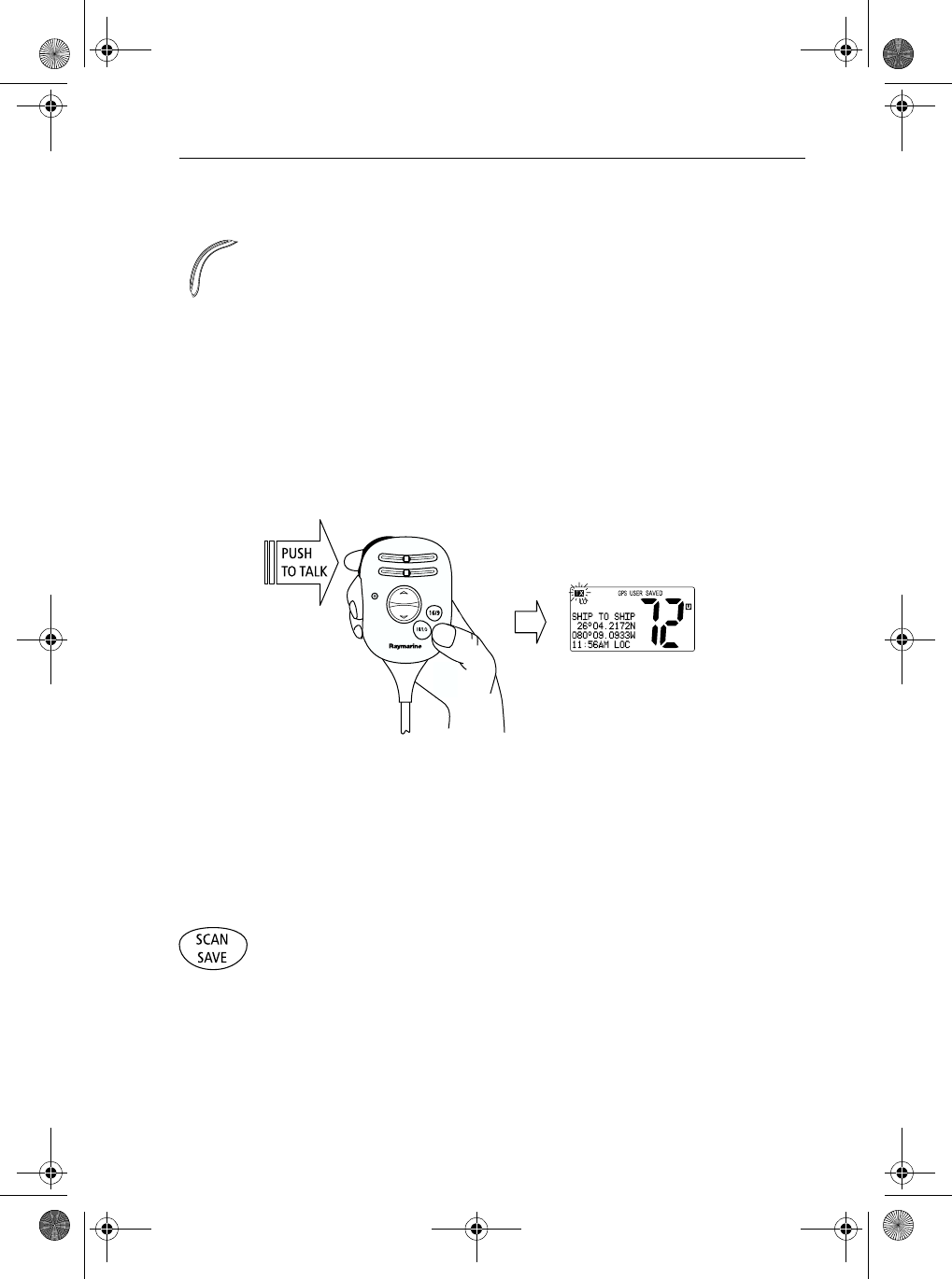
4.9 Transmitting
Press and hold the Push-to-Talk (PTT) key on the handset to transmit on the
selected channel, then release to receive. The TX indicator appears during
transmission.
Note: International regulations and good communications practice and dic-
tate that you should not interfere with other communications. Before trans-
mitting, listen to make sure the channel is clear.
The radio is equipped with a timeout timer in the event of a stuck key. After
PTT has been held continuously for 5 minutes, transmission is discontinued
and the radio automatically returns to receive mode. An Error beep is emitted
10 seconds before the time out is triggered and TX flashes on the display until
PTT is released.
The TX time out timer is reset once the PTT key is released.
Note: If the current channel is receive-only, an alarm sounds when PTT is
pressed, indicating such a transmission is not permitted.
4.10 Using the Scan Modes
The Ray54 is equipped with three types of scan options: All Scan, Saved
(Memory) Scan and Priority Scan. If there are no channels in memory, the
default is All Scan.
This function automatically searches for broadcasting channels. If a TX
signal is received, the scan stops on the receiving channel as long as it is
present. If the signal is lost for five seconds, the radio resumes scanning.
During the Scan Modes:
81231_1.book Page 27 Thursday, April 22, 2004 5:21 PM
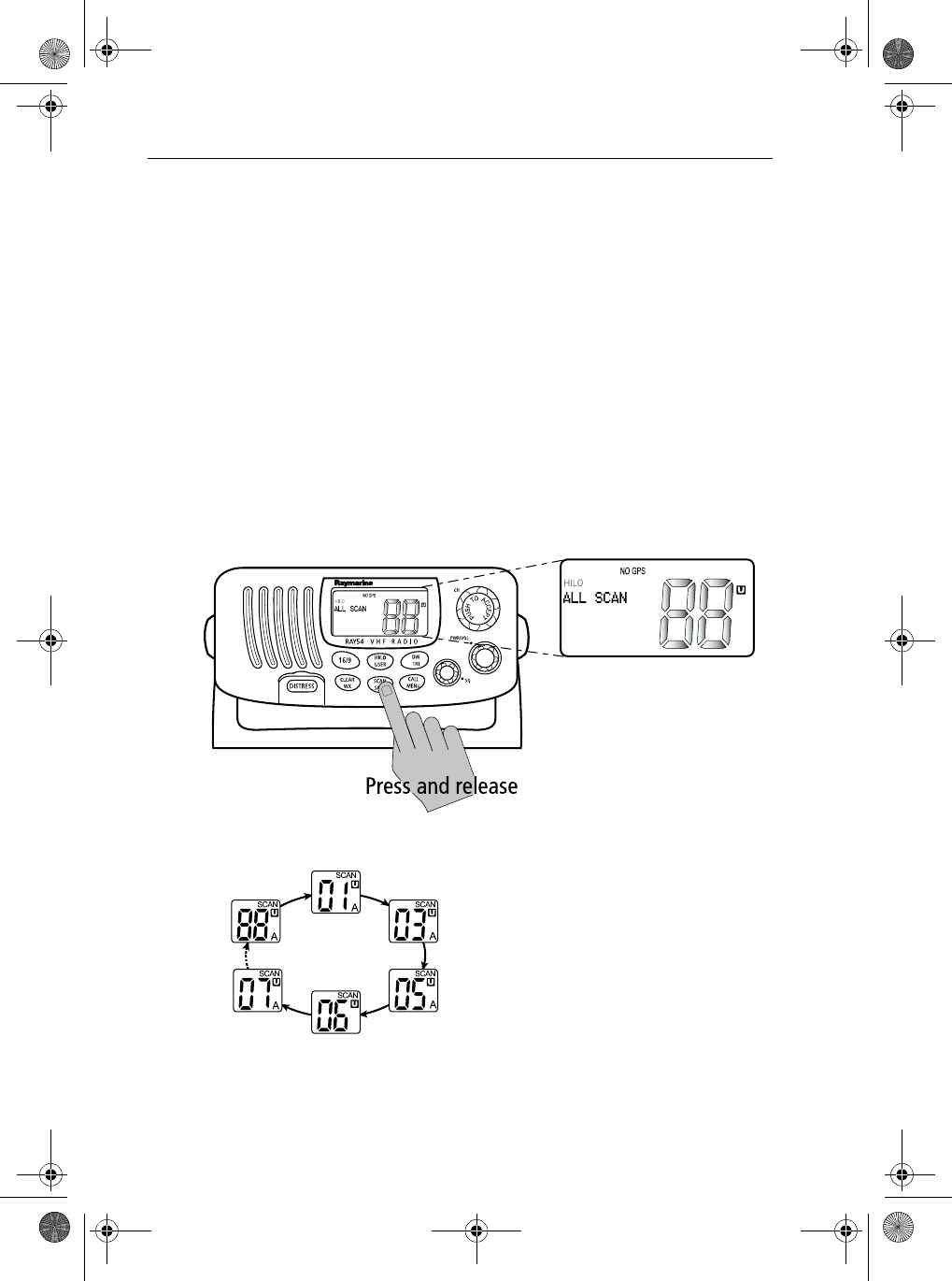
28 Ray54 VHF Radio
•Press the Channel UP/DOWN key or rotate the CH knob to change the
scan direction. UP(CH key)/clockwise (CH knob) increments the chan-
nel while DOWN (CH key) /counterclockwise (CH knob) decrements it.
•Press PTT to halt the scan and transmit at the displayed channel.
•Press and release SCAN/SAVE to terminate the SCAN mode and return to
the last-used channel.
•Press and release CLEAR/WX to terminate the SCAN mode and return to
the last-used channel.
•DW/TRI and HILO/USER keys will not function and sounds an error beep
if pressed.
All Scan
Press and release the SCAN/SAVE key when no channels are stored in
memory to activate the All Scan function.
ALL SCAN appears on the dot matrix display.
In All Scan mode, all channels in the
channel set are scanned in sequence,
assuming no channels have been stored in
memory. After the last channel number has
been scanned, the cycle repeats.
All Scan is demonstrated in the figure to
the left.
81231_1.book Page 28 Thursday, April 22, 2004 5:21 PM
Chapter 4: General Operations 29
Note: Whenever Weather Alert is activated, the WX Alert channel is also
monitored during All Scan. If the WX Alert tone is detected, the scan is halted
to broadcast the Weather Alert message.
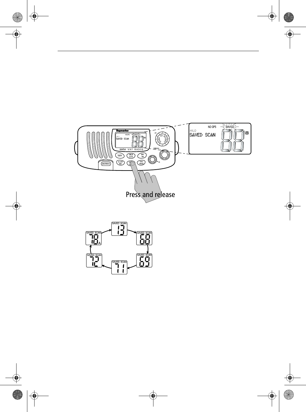
Saved (Memory) Scan
Press and release the SCAN/SAVE key when there is at least one channel in
memory to activate the Saved Scan function.
SAVED SCAN appears on the dot matrix display.
In Saved Scan mode, only the channels that
have been saved in memory are scanned in
sequence. After the last saved channel
number has been scanned, the cycle repeats.
Saved Scan is demonstrated in the figure to
the left.
Note: Whenever Weather Alert is activat-
ed, the WX Alert channel is also monitored during Saved Scan. If the WX
Alert tone is detected, the scan is halted to broadcast the Weather Alert mes-
sage.
81231_1.book Page 29 Thursday, April 22, 2004 5:21 PM
30 Ray54 VHF Radio
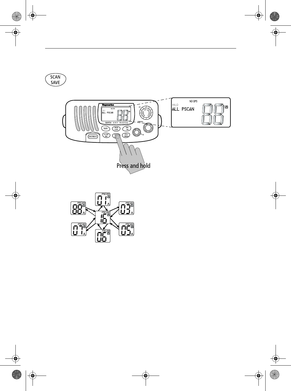
Priority All Scan
Press and hold the SCAN/SAVE key while All Scan is active to initiate
Priority Scan.
ALL PSCAN appears on the dot matrix display.
Priority Scan searches for activity on all
channels but alternates scanning the
Priority Channel 16 after each channel.
Priority Scan is demonstrated in the figure
to the left.
Note: Whenever Weather Alert is activated, the WX Alert channel is also
monitored during Priority All Scan. If the WX Alert tone is detected, the scan
is halted to broadcast the Weather Alert message.
81231_1.book Page 30 Thursday, April 22, 2004 5:21 PM
Chapter 4: General Operations 31
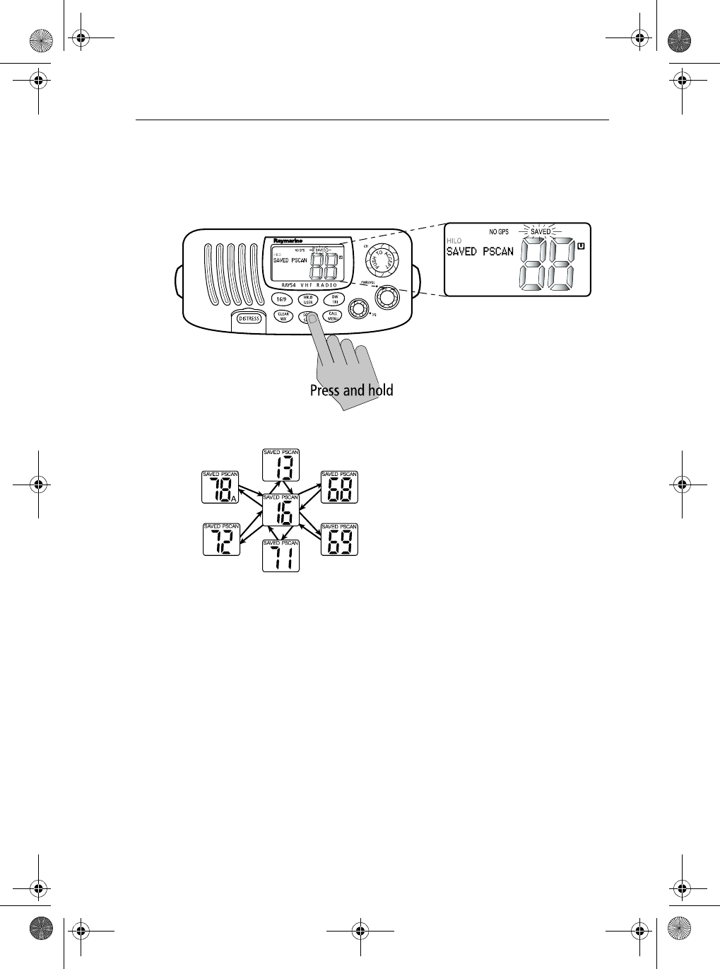
Priority Saved Scan
Press and hold the SCAN/SAVE key while Saved Scan is active to initiate
Priority Saved Scan.
SAVED PSCAN appears on the dot matrix display.
Priority Saved Scan is much like Priority
Scan except that the radio alternates
searching for activity on the Priority
Channel 16 and the channels stored in
memory.
Priority Saved Scan is demonstrated in the
figure to the left.
Note: Whenever Weather Alert is activated, the WX Alert channel is also
monitored during Priority Saved Scan. If the WX Alert tone is detected, the
scan is halted to broadcast the Weather Alert message.
Press and hold SCAN/SAVE for 3 seconds to exit Priority/Priority Saved
Scan and return to All/Memory Scan.
Press and release the CLEAR/WX key to exit Priority/Priority Saved Scan
and return to the last-used channel.
81231_1.book Page 31 Thursday, April 22, 2004 5:21 PM
32 Ray54 VHF Radio
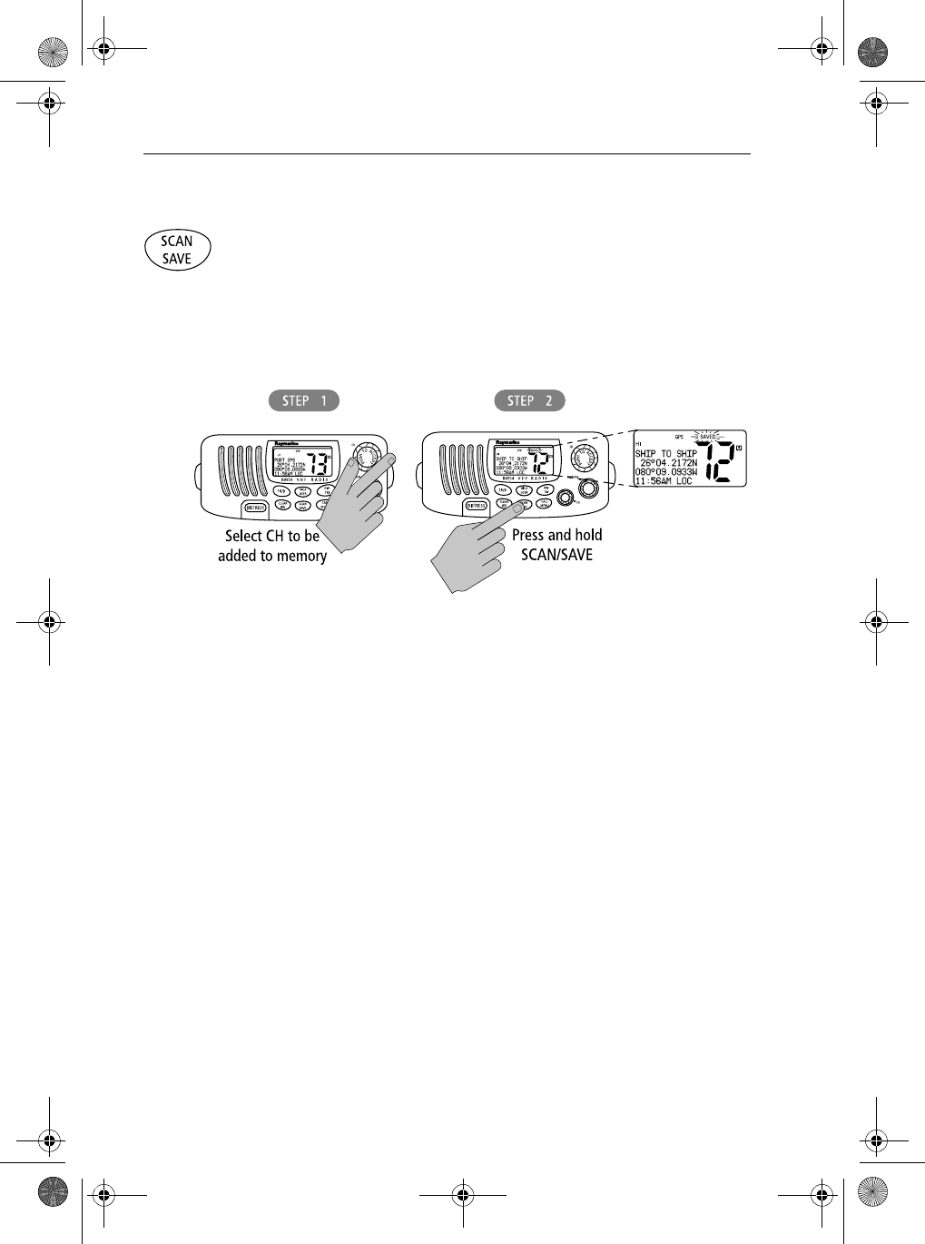
4.11 Adding Channels to Memory
The Ray54 can store any channel. The stored channels are the ones scanned
in the Saved (Memory) Scan mode.
➤To Add Channels to Memory
1. During normal operation mode, use the CH knob to select the desired
channel for programming.
2. Press and hold the SCAN/SAVE key for 3 seconds.
The SAVED icon appears to indicate the current channel has been saved in
memory. Any number of channels can be saved as memory channels.
Separate memory channel groups exists for USA, International, and
Canadian frequency sets.
➤To Delete Channels from Memory
1. During the normal mode, use the CH knob to select the channel to be
deleted.
2. Press and hold the SCAN/SAVE key for 3 seconds.
The selected channel is deleted from memory.
To view the channels set in memory, switch to USER mode, as described in
Section 4.13, USER Channel Mode.
81231_1.book Page 32 Thursday, April 22, 2004 5:21 PM
Chapter 4: General Operations 33
4.12 Using the Monitor Modes
The Watch Modes monitor the programmed Priority Channel and other user-
selected channel(s). The watch is halted when activity is detected on a
monitored channel. The Ray54 is equipped with 2 types of monitor
operations: Dual Watch and Tri Watch.
Dual Watch
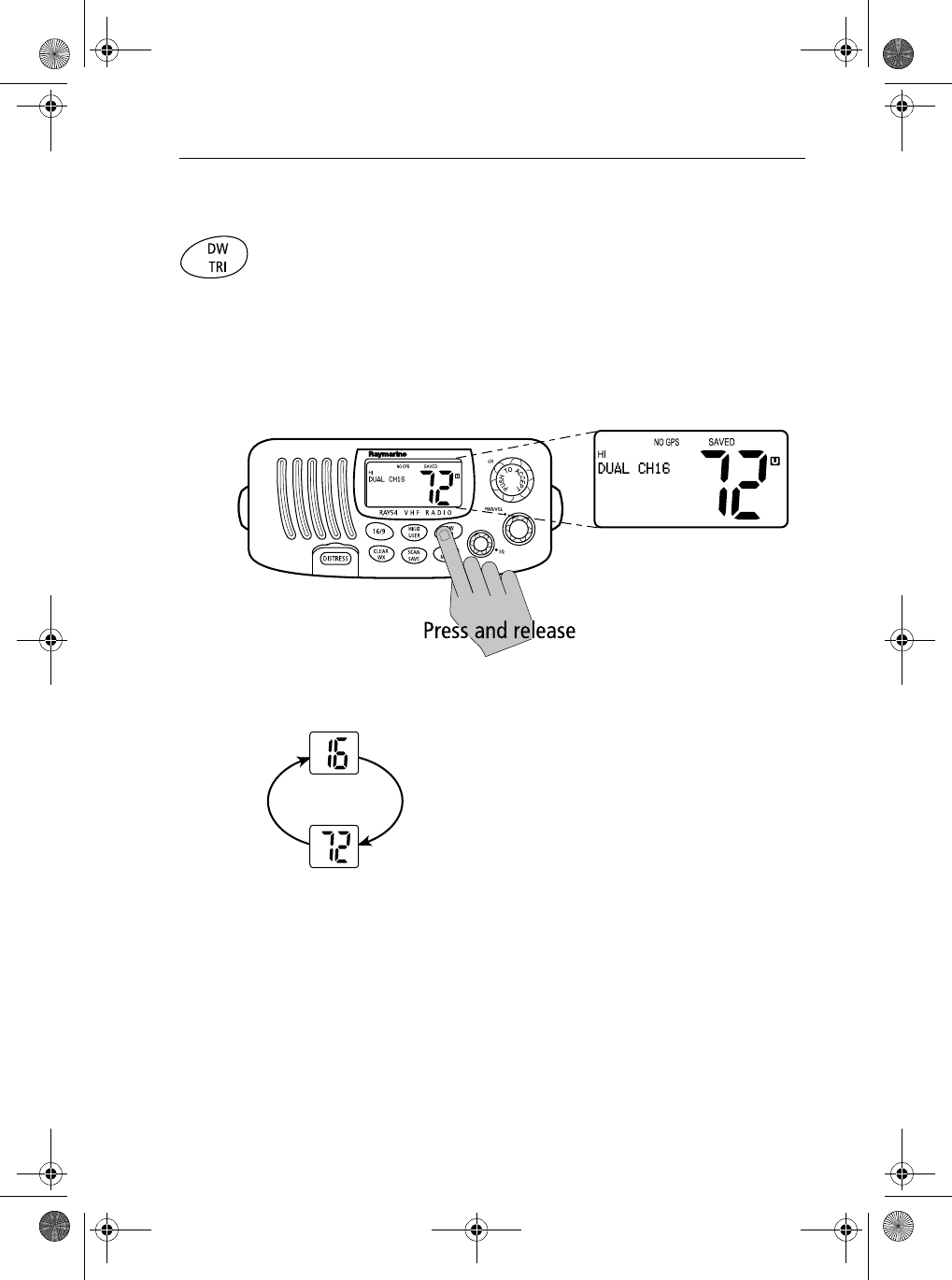
Press and release the DW/TRI key to activate the Dual Watch mode.
DUAL CH16 appears in the dot matrix display.
Dual Watch monitors the current working channel
and Channel 16 in cycle.
Dual Watch is demonstrated in the figure to the left;
the sample working channel is CH 72. Whenever
Weather Alert is activated, the WX Alert channel is
also monitored during Dual Watch.
Press and release the DW/TRI key to terminate Dual
Watch and return to the previous working channel.
Press and hold the DW/TRI key to terminate Dual Watch mode and go into
Tri Watch mode.
Press and release the CLEAR/WX key to terminate Dual Watch mode and
return to the last-used channel.
Press and release the 16/9 key to terminate Dual Watch mode and switch to
the Priority Channel.
81231_1.book Page 33 Thursday, April 22, 2004 5:21 PM
34 Ray54 VHF Radio
Note: During Dual Watch mode, the SCAN/SAVE, USER, WX and CH keys
are inactive and sounds an error beep if pressed.
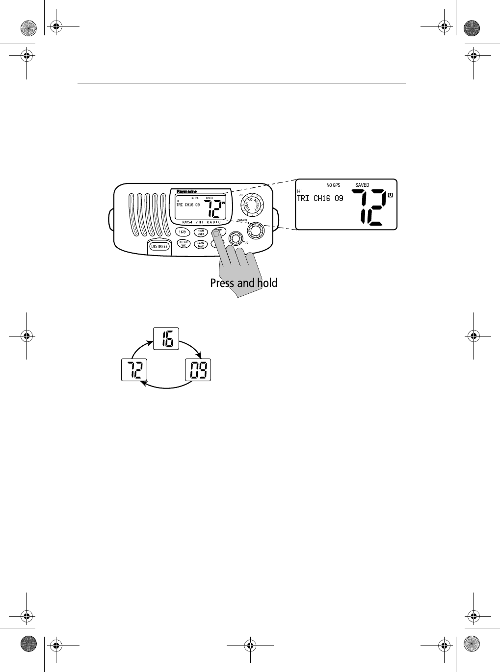
Tri Watch
Press and hold the DW/TRI key for 3 seconds to activate Tri Watch mode.
TRI CH16 09 appears on the dot matrix display.
Tri Watch monitors in cycle Channel 16, the
current working channel and the channel you
have set as the Secondary Priority Channel.
Tri Watch is demonstrated in the figure to the left;
the sample working channel is CH 72.
Note: Whenever Weather Alert is activated, the WX Alert channel is also
monitored during Tri Watch.
Press and release the DW/TRI key to terminate Tri Watch and return to the
previous working channel.
Press and release the 16/9 key to terminate Tri Watch mode and switch to
the Priority Channel.
Press and release the CLEAR/WX key to terminate Tri Watch mode and
return to the last-used channel.
Note: During Tri Watch Mode, the SCAN/SAVE, USER, WX and CH keys
are inactive and sounds an error beep if pressed.
81231_1.book Page 34 Thursday, April 22, 2004 5:21 PM
Chapter 4: General Operations 35
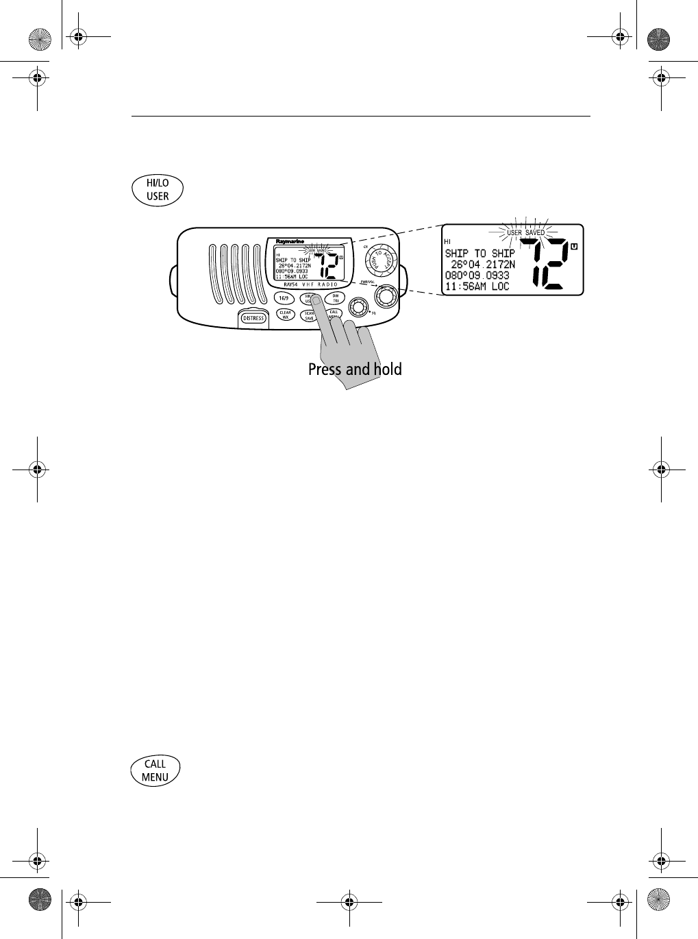
4.13 USER Channel Mode
Press and hold the HL/USER key while in normal operation mode to enter
User Mode. The USER and SAVED indicators appear.
USER Channel Mode displays only the channels that you have saved to
memory, which enables you to easily use your favorite channels while
bypassing unwanted or seldom-used channels during a scan.
Note: The procedure for saving a channel to memory is outlined in Section
4.11, Adding Channels to Memory.
While in User Mode:
•Press and release the SCAN/SAVE key to start Memory Scan mode.
•Press and hold the SCAN/SAVE key to delete the current channel from
memory list.
•Press 16/9 to end User mode and switch to the Priority Channel.
Press and release the CLEAR/WX key to quit User mode and return to the
last-used working channel.
Press and hold the HL/USER key for 3 seconds to quit User mode and return
to the last-used working channel.
Note: You cannot switch Channel sets while in User Mode.
4.14 DSC Call Operation
Press and release the CALL/MENU key while in normal operation mode to
enter Call Mode.
DSC Call mode is fully described in Chapter 5:
81231_1.book Page 35 Thursday, April 22, 2004 5:21 PM
36 Ray54 VHF Radio
4.15 Menu Mode Operation
Press and hold the CALL/MENU key while in normal operation mode to
enter Menu Mode.
Menu mode is fully described in Chapter 6:
81231_1.book Page 36 Thursday, April 22, 2004 5:21 PM