Flir BelgiumBA STNGB Low-power (unlicensed) wireless device for leisure User Manual 87070 1 GSeries Install Comm
Raymarine UK Ltd. Low-power (unlicensed) wireless device for leisure 87070 1 GSeries Install Comm
Contents
- 1. Gseries Reference Part 1
- 2. Gseries Reference Part 2
- 3. Gseries Installation Part 1
- 4. Gseries Installation Part 2
- 5. Gseries Base Station
Gseries Installation Part 1

G-Series
Systems
Installation and
Commissioning
Instructions

G-Series System
Installation & Commissioning Instructions
Document Number:87070_1
Date: June 2007

G-Series Installation & Commissioning 4
Trademarks and registered trademarks
Autohelm, HSB, Raymarine, RayTech, Sail Pilot, SeaTalk and Sportpilot are registered trademarks of Raymarine Limited. Apelco is a regis-
tered trademark of Raymarine Holdings Limited (Registered in all major marketing territories).
AST, Autoadapt, Auto GST, Autoseastate, Autotrim, Bidata, Marine Intelligence, Maxiview, On Board, Raychart, Raynav, Raypilot, Raystar,
ST40, ST60, Seaclutter, Smart Route, Tridata and Waypoint Navigation are trademarks of Raymarine Limited.
Maptech is a registered trademark of Maptech.
All other product names mentioned are trademarks or registered trademarks (if applicable) of their respective companies
© Raymarine plc 2007

5
Contents
Chapter 1: Introduction ..................................... 11
1.1 Handbook information .............................................. 12
1.2 Plan your installation ................................................ 12
1.3 Install your system ................................................... 12
1.4 Commissioning ........................................................ 13
Chapter 2: Typical systems .............................. 15
Chapter 3: Packs and contents ......................... 23
3.1 GPM400 processor .................................................. 24
3.2 GVM400 video module ............................................ 25
3.3 G-Series Keyboard .................................................. 26
3.4 Keyboard wireless upgrade kit ................................. 27
3.5 SeaTalkng wireless basestation ............................... 28
3.6 Marine monitors ....................................................... 28
3.7 Alarm buzzer ............................................................ 29
Chapter 4: Cables and connections ................. 31
4.1 General instructions ................................................. 32
4.3 GPM400 processor .................................................. 37
4.4 Monitor connections ................................................. 38
4.5 Keyboard connections ............................................. 40
4.6 Video and Entertainment ......................................... 43
4.7 SeaTalkhs network ................................................... 47
4.8 GPS Connection ...................................................... 49
4.9 SeaTalk & Alarm connection .................................... 50
4.10 NMEA 0183 connections ....................................... 51
4.11 SeaTalkng connections .......................................... 54
4.12 NMEA 2000 connections ....................................... 55
Chapter 5: Installation and mounting ................57
5.1 General instructions .................................................58
5.2 GPM400 Processor module .....................................59
5.3 G-Series Keyboard ...................................................60
5.4 G-Series Monitors ....................................................65
5.5 GVM400 Video Module ............................................66
5.6 Alarm buzzer ............................................................67
Chapter 6: Initial test ......................................... 69
6.1 Power up test ...........................................................70
Chapter 7: Initial Setup .....................................73
7.1 Power up the system ................................................74
7.2 First time configuration .............................................74
7.3 Select Master GPM ..................................................75
7.4 Configure Nav Stations ............................................77
7.5 Assign Keyboards ....................................................78
Chapter 8: Commissioning ................................ 81
8.1 Language setting ......................................................82
8.2 Compass heading setup ...........................................82
8.3 Radar setup ..............................................................83
8.4 GPS checks ..............................................................85
8.5 Fishfinder checks ....................................................86
8.6 Set up video .............................................................87
8.7 NMEA 0183 ..............................................................88
8.8 Data checks ..............................................................89
Chapter 9: Troubleshooting ..............................91
9.1 Troubleshooting ........................................................92
Appendix ATechnical specification.......................... 103
Appendix B - Nav Station schematic....................... 109
Appendix C - Spares and accessories .................... 117
Index ....................................................................... 121

G-Series Installation & Commissioning 6
7
Warnings and cautions
EMC installation guidelines
Raymarine equipment and accessories conform to the appropriate
Electromagnetic Compatibility (EMC) regulations. This minimizes
electromagnetic interference between equipment, which could oth-
erwise affect the performance of your system.
Correct installation is required to ensure that EMC performance is
not compromised.
For optimum EMC performance, we recommend that:
• Raymarine equipment and the cables connected to it are:
Product installation
This equipment must be installed and operated in
accordance with the Raymarine instructions
provided. Failure to do so could result in poor
product performance, personal injury, and/or
damage to your boat.
Potential ignition sources
The equipment in these instructions is NOT
approved for use in hazardous/flammable atmo-
spheres such as an engine room.
Switch off power supply
Make sure you have set the boat’s power supply
to OFF before you start installing this product.
Unless otherwise stated connect and disconnect
equipment only with the power supply switched
OFF.
High voltage
Equipment contains high voltages.
Unless otherwise instructed within these
instructions do not remove the covers or attempt
to access the internal components.
Grounding requirements
This display is not intended for use on “positive”
ground boats. The power input cable earth
screen connections must be connected directly
to the boats ground.
Radar
The radar scanner transmits electromagnetic
energy. Ensure all personnel are clear of the
scanner before switching to Tx (transmit mode)
Navigation aid
Raymarine equipment is intended for use only as
an aid to navigation. You must still ensure that a
properly qualified person is acting as navigator
at all times and that all applicable maritime regu-
lations are adhered to. You must also ensure that
all proper judgements and actions are taken to
ensure a safe passage. Always maintain a perma-
nent watch
Service and Maintenance
This product contains no user serviceable
components. Please refer all maintenance and
repair to authorized Raymarine dealers.
Unauthorized repair may affect your warranty.
Sun covers
To provide protection against the damaging
effects of ultra violet (UV) light, use the sun
covers when equipment is not in use.
Cleaning
DO NOT use acid, ammonia based or abrasive
products.
DO NOT use commercial high pressure washing
(jet wash) equipment.

G-Series Installation & Commissioning 8
i. At least 3 ft. (1 m) from any equipment transmitting or cables
carrying radio signals e.g. VHF radios, cables and
antennas. In the case of SSB radios, the distance should be
increased to 7 ft. (2 m).
ii. More than 7 ft. (2 m) from the path of a radar beam. A radar
beam can normally be assumed to spread 20 degrees
above and below the radiating element.
• The product is supplied from a separate battery from that used
for engine start. This is important to prevent erratic behavior
and data loss which can occur if the engine start does not have
a separate battery.
• Raymarine specified cables are used.
• Cables are not cut or extended unless doing so is detailed in the
installation manual.
Remember
Where constraints on the installation prevent any of the above
recommendations:
• Always allow the maximum separation possible between differ-
ent items of electrical equipment. This will provide the best
conditions for EMC performance for the installation.
Suppression ferrites
Raymarine cables may be fitted with suppression ferrites. These
are important for correct EMC performance. Any ferrite removed to
facilitate installation must be replaced in the original position imme-
diately installation is complete.
• Use only ferrites of the correct type, supplied by Raymarine au-
thorized dealers.
Connections to other equipment
If Raymarine equipment is to be connected to other equipment
using a cable not supplied by Raymarine, a Raymarine suppres-
sion ferrite MUST always be attached to the cable near the
Raymarine unit.
Waste Electrical and Electronic Equip-
ment Directive
The Waste Electrical and Electronic Equipment (WEEE)
Directive requires the recycling of waste electrical and
electronic equipment. Whilst the WEEE Directive does not
apply to some of Raymarine’s products, we support its pol-
icy and ask you to be aware of how to dispose of this
product.
The crossed out wheeled bin symbol, illustrated above, and found
on our products signifies that this product should not be disposed of
in general waste or landfill.
Please contact your local dealer, national distributor or Raymarine
Technical Services for information on product disposal.
Water ingress
As it exceeds the water proof rating capacity outlined by standards
CFR46 / IPX7, subjecting any Raymarine equipment to commercial
high pressure washing equipment may cause subsequent water
intrusion and failure of the equipment. Raymarine will not warranty
equipment subjected to high pressure washing
Warranty
To register your new Raymarine product, please take a few minutes
to fill out the warranty card included in the box or go to:
www.raymarine.com
It is important that you complete the owner information and return
the card to receive full warranty benefits, including notification of
software updates if they are required.

9
Disclaimer
The technical and graphical information contained in this hand-
book, to the best of our knowledge, was correct as it went to press.
However, our policy of continuous improvement and updating may
change product specifications without prior notice. As a result,
unavoidable differences between the product and handbook may
occur from time to time. Raymarine cannot accept responsibility for
any inaccuracies or omissions it may contain. For the latest product
information visit our website - www.raymarine.com

G-Series Installation & Commissioning 10

1
Chapter 1: Introduction
This guide provides information to help you plan, install and commission your G-Series system.
Chapter contents
• 1.1 Handbook information on page 12.
• 1.2 Plan your installation on page 12.
• 1.3 Install your system on page 12.
• 1.4 Commissioning on page 13.
See also
You may require additional information when planning or installing your system.
•Spares and accessories.
Lists of spares, accessories and cables can be found in Appendix C - Spares and accessories.
•Raymarine handbooks and manuals.
All additional documents referred to in this manual can be downloaded from the Raymarine website.
wwww.raymarine.com/handbooks.
G-Series Installation & Commissioning 12
1.1 Handbook information
This document is part of a series of books associated with the G-
Series system
All documents can be downloaded from:
www.raymarine.com/handbooks.
G-Series handbooks
Additional handbooks
You may also refer to separate instructions provided with the asso-
ciated ancillary equipment.
1.2 Plan your installation
Prior to installing your G-Series system you will need to plan care-
fully. Use the information in this guide to assist you.
1.3 Install your system
Once you have completed the planning stage, proceed with the
installation:
Title Part number
Installation and commissioning instructions 87070
Operating guide 86126
User reference guide 81276
Tick Planning for Installation instructions
Overall system Chapter 2: Typical systems
Chapter 3: Packs and contents
Equipment location Chapter 5: Installation and mounting
Power, supply and
distribution
Chapter 4: Cables and connections
Connections and cables Chapter 4: Cables and connections
Nav Station details Appendix B - Nav Station schematic
We strongly recommend that you produce a complete schematic diagram for
your G-Series installation. See Appendix B - Nav Station schematic.
Tick Installation task Installation instructions
Ensure you have all
required equipment,
accessories and cables.
Chapter 3: Packs and contents
Chapter 4: Cables and connections
Appendix C - Spares and accessories
Site all equipment. Chapter 5: Installation and mounting
Route all cables. Chapter 4: Cables and connections
Drill cable and mounting
holes.
Chapter 5: Installation and mounting
Make all connections into
equipment.
Chapter 4: Cables and connections
Power on test the system. Chapter 6: Initial test
Secure all equipment in
place.
Chapter 5: Installation and mounting

13 Chapter 1: Introduction
1.4 Commissioning
Once you have completed the installation, proceed with the com-
missioning of the system:
Tick Commissioning
task Installation instructions
Assign master GPM Chapter 7: Initial Setup
Set up Nav Stations Chapter 7: Initial Setup
Assign keyboards Chapter 7: Initial Setup
Commission ancillary
equipment
Chapter 8: Commissioning
Complete warranty cards
for equipment installed
Refer to separate warranty booklets
supplied with equipment.

G-Series Installation & Commissioning 14

2
Chapter 2: Typical systems
This section provides an overview of typical G-Series systems and ancillary equipment.
Chapter contents
• System overview on page 16
• Single processor system on page 17
• Dual Nav station (single processor) on page 18
• Network system, Single Nav station (Dual processor) on page 19
• Dual Nav station (Dual processor 2) on page 20
• Entertainment system on page 21
• System limits on page 22
See also
•Cables and connections on page 31
G-Series Installation & Commissioning 16
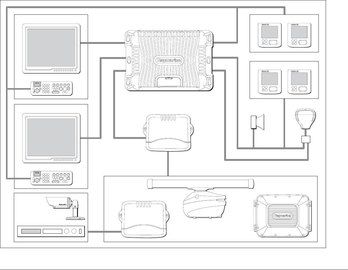
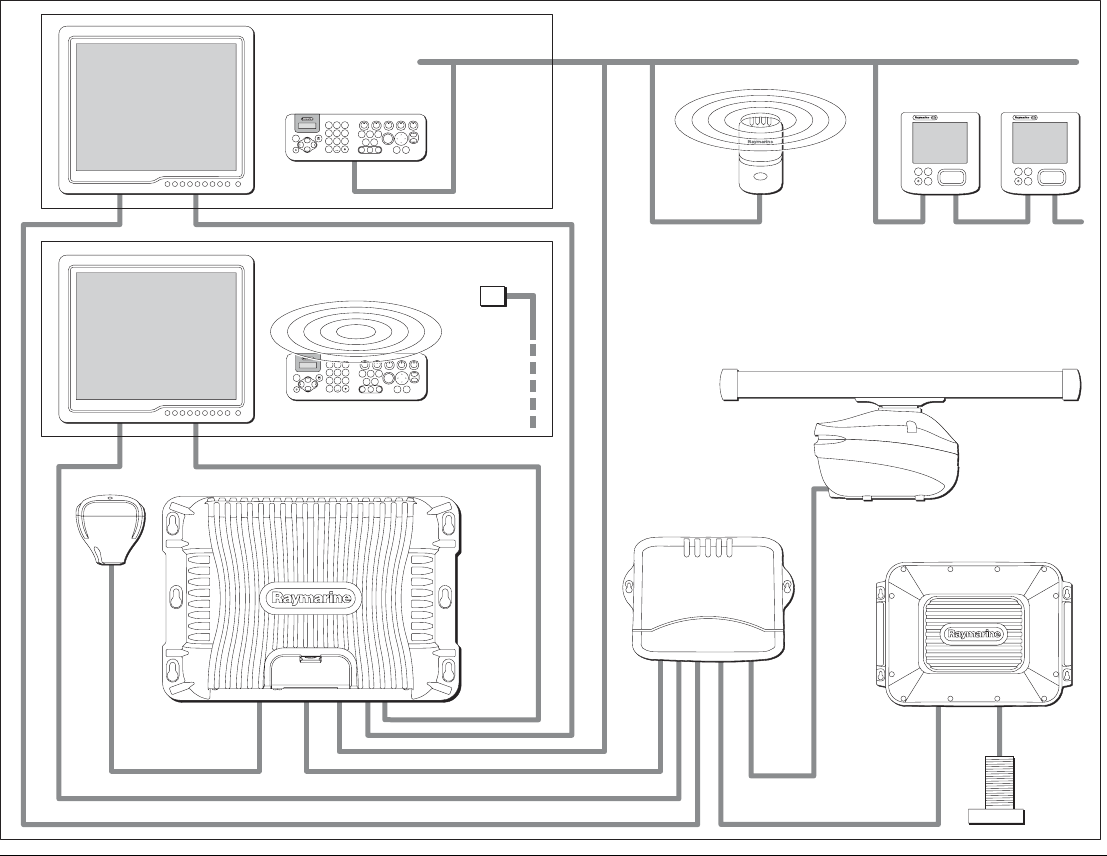
System overview
Note: Where 2 displays are connected to a single processor, both will display the same information.
D9985-1
ENTERCANCEL
MENU
ENTERCANCEL
MENU
Navstation 1 (e.g. Flybridge)
Navstation 2 (e.g. Bridge)
9
WXYZ
8
TUV
7
PQRS
4
GHI
5
JKL
6
MNO
ACTIVE
WPTS
MOB
DATA
MENU
PAGE
.0
2
ABC
3
DEF
1
CANCEL
STANDBY
DODGE PILOT OK
RANGE
OUT
IN
ENTER
ENTERCANCEL
MENU
ENTERCANCEL
MENU
9
WXYZ
8
TUV
7
PQRS
4
GHI
5
JKL
6
MNO
ACTIVE
WPTS
MOB
DATA
MENU
PAGE
.0
2
ABC
3
DEF
1
CANCEL
STANDBY
DODGE PILOT OK
RANGE
OUT
IN
ENTER
Keyboard
Monitor
SeaTalk
Alarm
sounder
SeaTalkhs
SeaTalkhs
SeaTalkng
SeaTalkhs
network devices
SeaTalkng
DVI or VGA
DVI or VGA
NMEA 0183 or SeaTalk
GPS
SeaTalkhs switch
and/or
SeaTalk instruments/pilot
Keyboard
GPM 400
Digital radar
Video module
Video/audio
sources
OR
DSM digital sounder
(or other compatible
digital server)
Monitor
SeaTalkng instruments/pilot
17 Chapter 2: Typical systems
Single processor system
ENTERCANCEL
MENU
ENTERCANCEL
MENU
C/lines for plugs/sockets
Navstation Monitor
Transducer
Digital radar
Pilot Instrument
Alarm
sounder
GPS
SeaTalkhs switch
GPM 400 (Central processor)
Audio OUT
(to ship's
audio system)
D9987-1
SeaTalkng backbone
DVI or VGA
SeaTalk/Alarm output
SeaTalk
SeaTalkhs SeaTalkhs
SeaTalkhs
SeaTalkhs
SeaTalkhs
SeaTalkhs
SeaTalkng
DSM digital sounder
9
WXYZ
8
TUV
7
PQRS
4
GHI
5
JKL
6
MNO
ACTIVE
WPTS
MOB
DATA
MENU
PAGE
.0
2
ABC
3
DEF
1
CANCEL
STANDBY
DODGE PILOT OK
RANGE
OUT
IN
ENTER
Keyboard
SeaTalkng
G-Series Installation & Commissioning 18
Dual Nav station (single processor)
9
WXYZ
8
TUV
7
PQRS
4
GHI
5
JKL
6
MNO
ACTIVE
WPTS
MOB
DATA
MENU
PAGE
.0
2
ABC
3
DEF
1
CANCEL
STANDBY
DODGE PILOT OK
RANGE
OUT
IN
ENTER
9
WXYZ
8
TUV
7
PQRS
4
GHI
5
JKL
6
MNO
ACTIVE
WPTS
MOB
DATA
MENU
PAGE
.0
2
ABC
3
DEF
1
CANCEL
STANDBY
DODGE PILOT OK
RANGE
OUT
IN
ENTER
ENTERCANCEL
MENU
ENTERCANCEL
MENU
C/lines for plugs/sockets
Keyboard
Wireless
keyboard
Monitor
Monitor
Wireless
base station
InstrumentPilot
GPS
SeaTalkhs switch
DVI or VGA
DVI or VGA
DVI or VGA
SeaTalk
or NMEA 0183
GPM 400
D9988-1
Transducer
DSM digital sounder
Digital radar
Charger
point
SeaTalkng backbone
SeaTalkhs
SeaTalkhs
SeaTalkhs
SeaTalkhs
SeaTalkng
SeaTalkng
SeaTalkng
To SeaTalkng
SeaTalkng
Navstation, (e.g. Bridge)
Navstation, (e.g. Flyridge)
19 Chapter 2: Typical systems
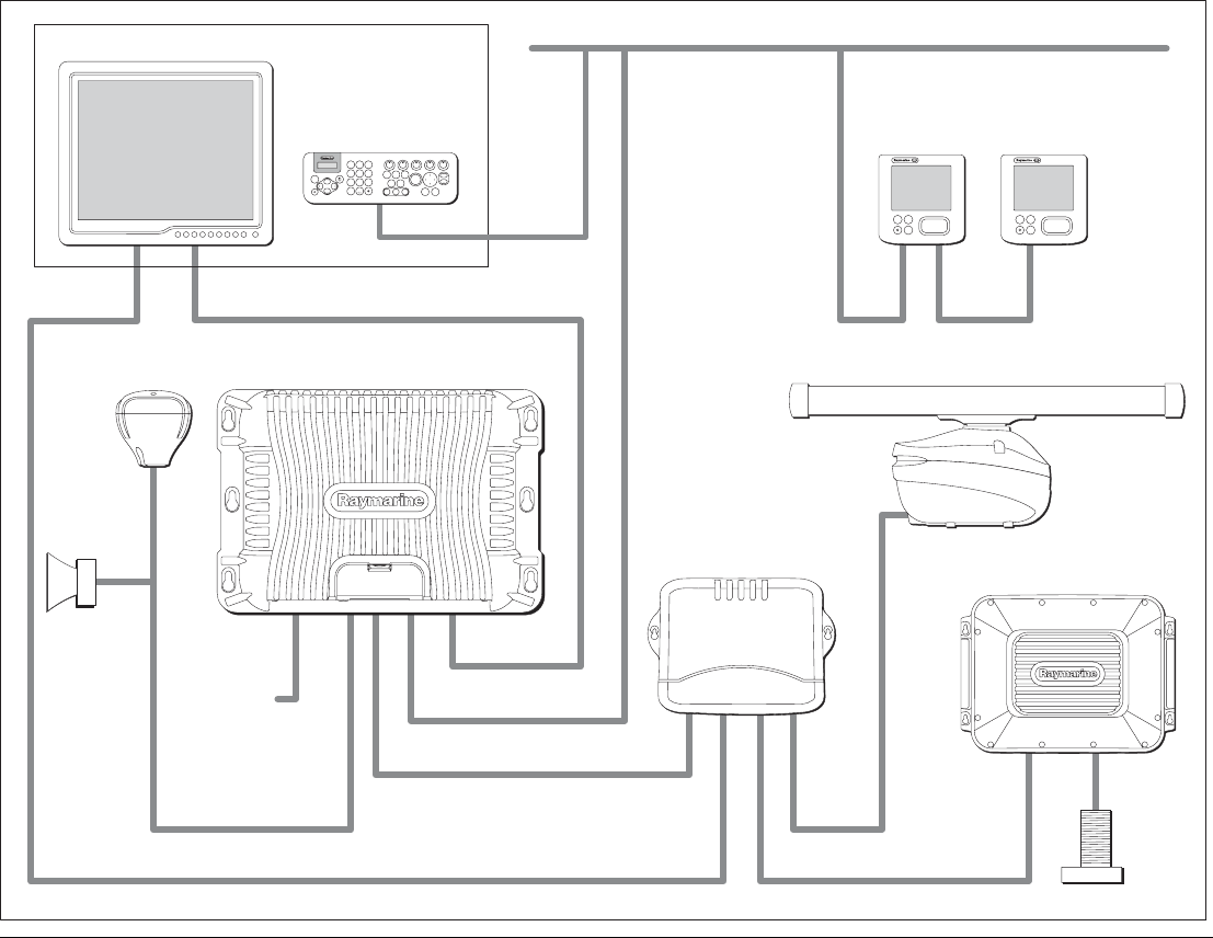
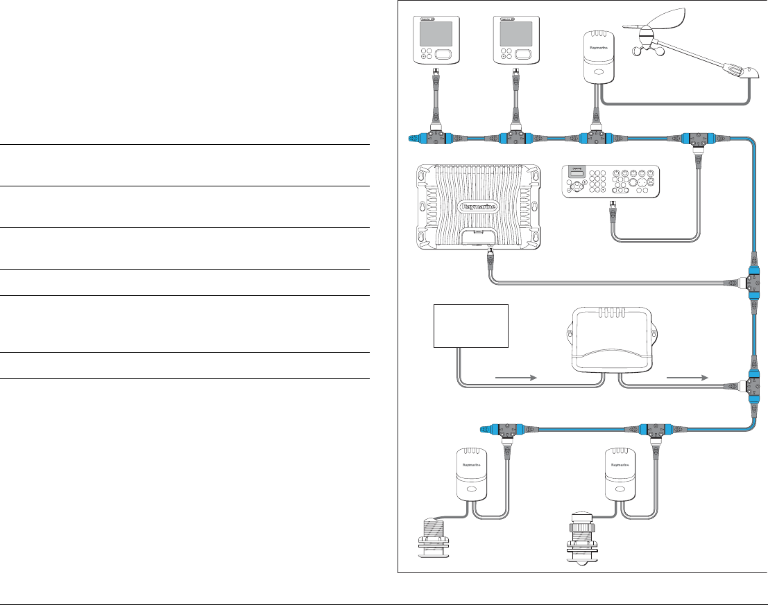
Network system, Single Nav station (Dual processor)
Note: Each display at a Nav station must be connected to a different GPM400. DIsplays sharing a GPM will both display identical
information.
SeaTalkng backbone
9
WXYZ
8
TUV
7
PQRS
4
GHI
5
JKL
6
MNO
ACTIVE
WPTS
MOB
DATA
MENU
PAGE
.0
2
ABC
3
DEF
1
CANCEL
STANDBY
DODGE PILOT OK
RANGE
OUT
IN
ENTER
ENTERCANCEL
MENU
ENTERCANCEL
MENU
D9989-1
Digital radar
InstrumentInstrument
SeaTalkhs switch
S-video
AV
Video module
Camera
Sat
TV
GPM400 GPM400 Data Master
Monitor Monitor
Keyboard
DVI or VGA DVI or VGA
SeaTalkhs
SeaTalkhs
SeaTalkhs
SeaTalkhs
SeaTalkhs
SeaTalkhs
SeaTalkng
SeaTalkng
SeaTalkng
SeaTalkng
DSM digital sounder
G-Series Installation & Commissioning 20
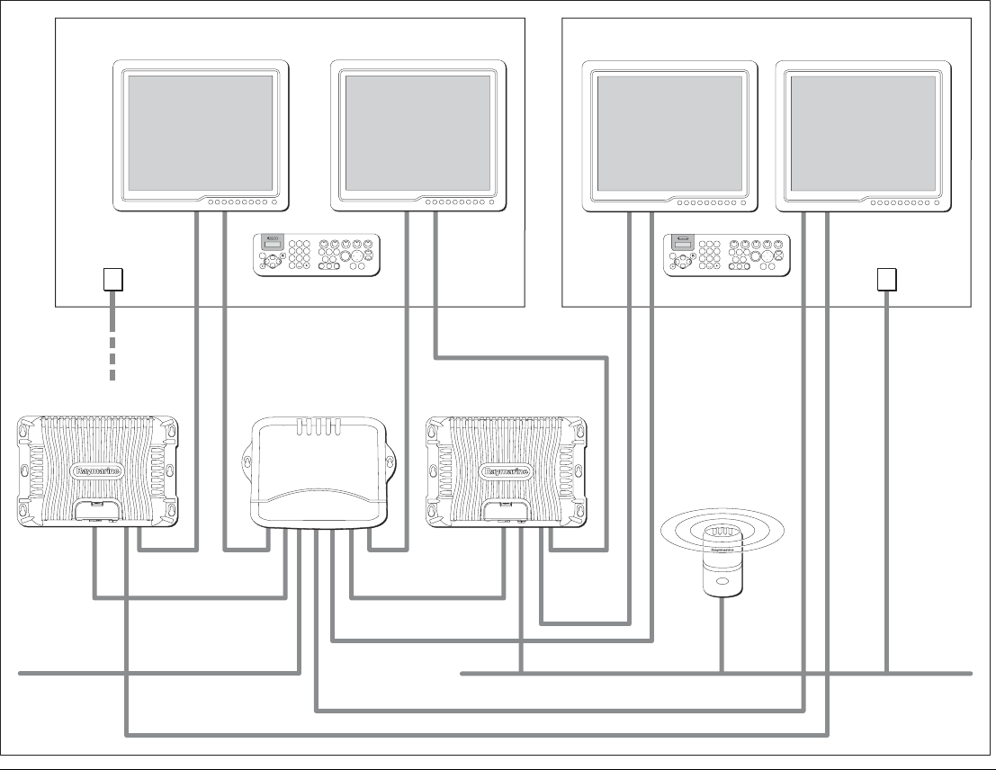
Dual Nav station (Dual processor 2)
9
WXYZ
8
TUV
7
PQRS
4
GHI
5
JKL
6
MNO
ACTIVE
WPTS
MOB
DATA
MENU
PAGE
.0
2
ABC
3
DEF
1
CANCEL
STANDBY
DODGE PILOT OK
RANGE
OUT
IN
ENTER
9
WXYZ
8
TUV
7
PQRS
4
GHI
5
JKL
6
MNO
ACTIVE
WPTS
MOB
DATA
MENU
PAGE
.0
2
ABC
3
DEF
1
CANCEL
STANDBY
DODGE PILOT OK
RANGE
OUT
IN
ENTER
D9990-1
SeaTalkhs switch
GPM400 GPM400 (data master)
Monitor Monitor Monitor Monitor
SeaTalkng
devices
DVI or VGA
DVI or VGA
DVI or VGA
DVI or VGA
DVI or VGA
SeaTalkhs
SeaTalkhs
SeaTalkhs
SeaTalkhs
SeaTalkhs
SeaTalkhs
SeaTalkhs
SeaTalkng
SeaTalkhs
SeaTalkhs
Keyboard
charge point
Keyboard
charge point
Wireless
Base station
Other SeaTalkhs
equipment
(radar,DSM)
SeaTalkng backbone
Navstation 1 (e.g. Bridge) Navstation 2 (e.g. Flybridge)
To SeaTalkng
21 Chapter 2: Typical systems
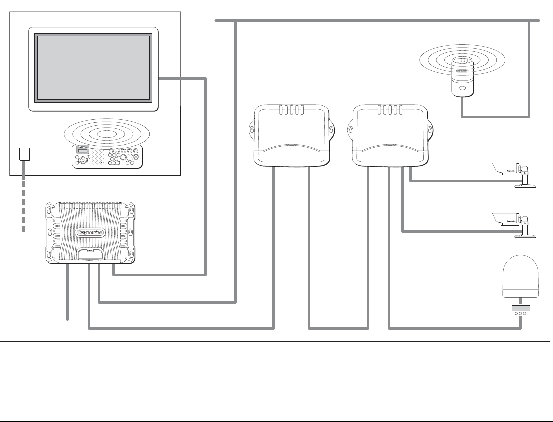
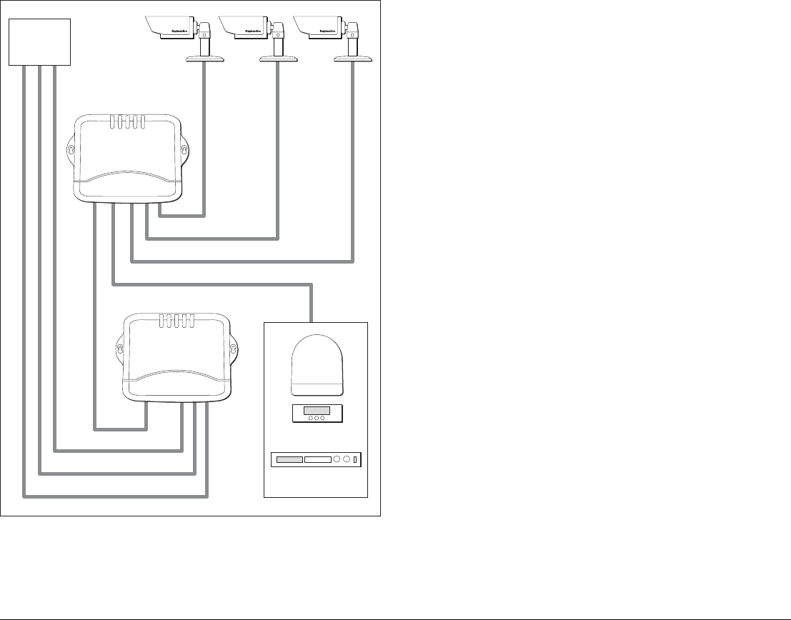
Entertainment system
Note: The system may include up to 2 Video modules to provide additional video capacity.
9
WXYZ
8
TUV
7
PQRS
4
GHI
5
JKL
6
MNO
ACTIVE
WPTS
MOB
DATA
MENU
PAGE
.0
2
ABC
3
DEF
1
CANCEL
STANDBY
DODGE PILOT OK
RANGE
OUT
IN
ENTER
D9991-1
SeaTalkhs switch
S-video
AV
AV
Video module
Audio out
Camera
Camera
Sat
TV
GPM 400 (Central processor)
Plasma Television
Basestation
Wireless
Keyboard
SeaTalkhs
SeaTalkhs
SeaTalkng
SeaTalkng
To SeaTalkng
DVI or VGA
Keyboard
charge point
SeaTalkng backbone

G-Series Installation & Commissioning 22
System limits
The following quantities of G-Series components may be
connected within a single system:
See also
For limitations associated with ancilliary components and systems,
refer to the separate manufacturer’s documentation.
G-Series component Max. number on system
GPM400 processor module 4
(of which 1 must be set as master
GPM)
Monitors 8
(2 per GPM400 processor)
Keyboards 8
GVM400 video module 2
DSM digital sounder 1
Digital radar scanner 2

3
Chapter 3: Packs and contents
This section contains details of pack contents for the G-Series system components.
Chapter contents
• 3.1 GPM400 processor on page 24
• 3.2 GVM400 video module on page 25
• 3.3 G-Series Keyboard on page 26
• 3.4 Keyboard wireless upgrade kit on page 27
• 3.5 SeaTalkng wireless basestation on page 28
• 3.6 Marine monitors on page 28
• 3.7 Alarm buzzer on page 29
See also
• For peripheral components (e.g. GPS antenna) refer to the separate instructions supplied with the
equipment.
G-Series Installation & Commissioning 24
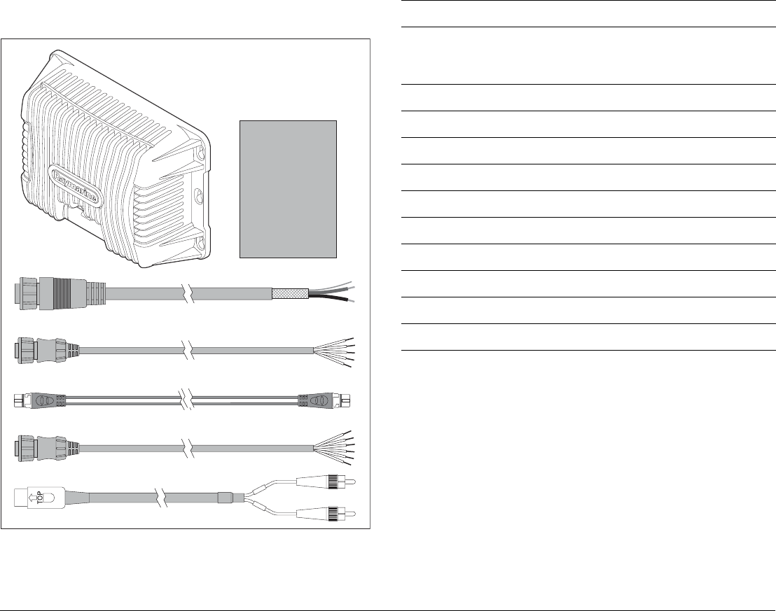
3.1 GPM400 processor
Pack items
SeaTalkng spur cable
D10062-1
GPM400 NMEA cable
GPM400 Power cable
GPM400 Audio cable
GPM400 SeaTalk/Alarm cable
GPM400
Processor Module
Handbook/documentation
Description Part No.
GPM400 Processor module - US version
GPM400 Processor module - EU version
GPM400 Processor module - ROW version
E02042
E02047
E02048
1.5 m (4.9 ft) Power cable R08003
1.5 m (4.9 ft) NMEA 0183 cable R08004
1 m (3.3 ft) SeaTalkng spur cable A06039
1.5 m (4.9 ft) SeaTalk/Alarm Out cable E55054
3 m (9.8 ft) G-Series Audio out cable R08266
Install pack R08295
User documentation CD 47018
Commissioning and installation guide 87070
Quick reference guide 86126
Warranty booklet 80017
25 Chapter 3: Packs and contents
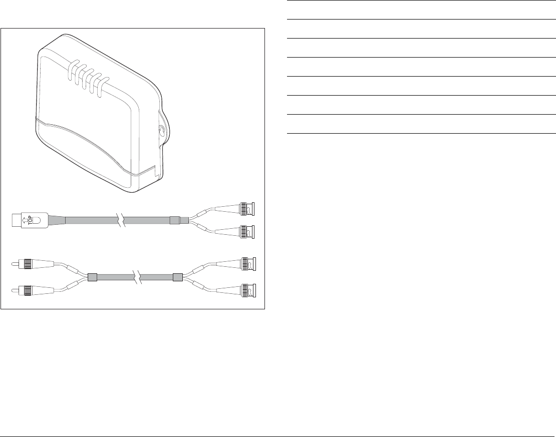
3.2 GVM400 video module
Pack items
GVM400 S-video cable
GVM400 audio cable
D10063-1
GVM400
Audio/Visual server unit
Description Part No.
GVM400 Video Module E02043
1.5 m (4.9 ft) S-Video cable R08274
1.5 m (4.9 ft) Audio cable R08275
Install pack R08318
Installation sheet 87068
Warranty booklet 80017
G-Series Installation & Commissioning 26
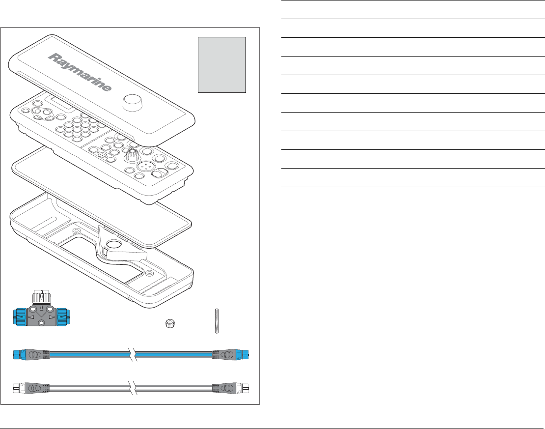
3.3 G-Series Keyboard
Pack items
D10065-1
Suncover
Handbook/
Documentation
Command
center keyboard
Panel seal
Stud (x4)
Finger
nut (x4)
Rear clamp
assembly
SeaTalkng backbone cable
SeaTalkng spur cable
SeaTalkng T connector
Description Part No.
G-Series command center keyboard E02044
Sun cover R08307
1 m (3.3 ft) SeaTalkng/NMEA2000 cable A06039
400 mm (15.75 in) SeaTalkng backbone cable A06033
SeaTalkng T-piece connector A06028
Rear cover / mounting bracket R08308
Screw pack R08309
Installation sheet 87084
Warranty booklet 80017
27 Chapter 3: Packs and contents
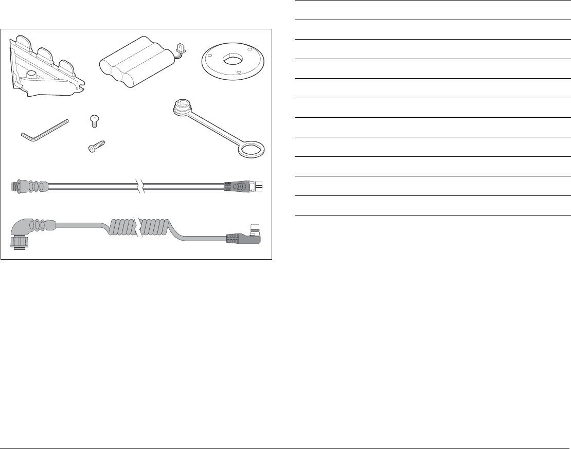
3.4 Keyboard wireless upgrade kit
Pack items
Battery pack
Connector cover
D10066-1
Handset dust cover
Allen head screw (x4)
Screw (x3)
Mounting plate
SeaTalkng bulkhead mounting cable
SeaTalkng Command Center charge cable
Allen key
Description Part No.
SeaTalkng bulkhead mounting cable R08311
2.5 m (8.2 ft) keyboard charge cable R08310
Battery pack R08312
4 x allen head M3 screws R08313
Mounting plate R08314
Connector cover R08315
Mounting screws (self tapping) x 3 R08316
Dust cap (covers dash mount cnx) R08317
Allen key R08338
Installation Sheet 87085
G-Series Installation & Commissioning 28
3.5 SeaTalkng wireless basestation
Pack items
3.6 Marine monitors
Pack items
Description Part No.
Wireless basestation E02045
1 m (3.3 ft) SeaTalk NG spur cable - stripped ends A06043
400 mm (15.75 in) SeaTalkng backbone cable A06033
SeaTalk NG T-connector A06028
Installation instructions 87086
SeaTalk
ng
backbone cable
SeaTalk
ng
spur cable
SeaTalk T connector
D10067-1
SeaTalk
ng
wireless basestation
Description Part No.
17” Marine Display
19” Marine Display
E02036
E02037
Sun cover Part numbers
depend on the
display model.
Refer to your
display handbook
for details
2 x mounting brackets
5 m (16.4 ft) VGA cable
1.5 m (4.9 ft) Power cable
Marine
display
Sun cover
1.5 meter Power Cable
5 meter VGA cable assembly
Mounting brackets x 2
D10363-1
29 Chapter 3: Packs and contents
3.7 Alarm buzzer
Pack items
Description Part No.
Alarm buzzer E26033
D10363-1

G-Series Installation & Commissioning 30

4
Chapter 4: Cables and connections
This section contains details of cables and connections. Use it to plan your system wiring and ensure that you
have the necessary cables available.
Chapter contents
• 4.1 General instructions on page 32
• 4.2 Power distribution on page 33
• 4.3 GPM400 processor on page 37
• 4.4 Monitor connections on page 38
• 4.5 Keyboard connections on page 40
• 4.6 Video and Entertainment on page 43
• 4.7 SeaTalkhs network on page 47
• 4.8 GPS Connection on page 49
• 4.9 SeaTalk & Alarm connection on page 50
• 4.10 NMEA 0183 connections on page 51
• 4.11 SeaTalkng connections on page 54
• 4.12 NMEA 2000 connections on page 55
G-Series Installation & Commissioning 32
4.1 General instructions
Cable types and length
• Follow the guidelines given in this section to determine appro-
priate cable types and length.
• Unless otherwise stated use only standard cables of the correct
type, supplied by Raymarine.
• Ensure that any non-Raymarine cables are of the correct quality
and gauge. For example, longer power cable runs may require
larger wire gauges to minimize any voltage drop in a cable.
Routing cables
• No acute bends. Minimum bend radius of 100mm.
• Protect all cables from physical damage and exposure to heat.
Use trunking or conduit where possible. Avoid running cables
through bilges or doorways, or close to moving or hot objects.
• Secure cables in place using tie-wraps or lacing twine. Coil any
extra cable and tie it out of the way.
• Where a cable passes through an exposed bulkhead or deck-
head, a watertight feed-through should be used.
You should always route data cables:
• as far apart from other equipment and cables as possible,
• as far away from high current carrying AC and DC power lines
as possible,
• as far away from antennas as possible.
Strain relief
• Ensure adequate strain relief is provided. Protect connectors
from strain and ensure they will not pull out under extreme sea
conditions.
Circuit isolation
For installations using both AC and DC current:
• Always use isolating transformers or a separate power-inverter
to run PC’s, processors, displays and other sensitive electronic
instruments or devices.
• Always use an isolating transformer with Weather FAX audio
cables.
• Always use and RS232/NMEA converter with optical isolation
on the signal lines.
• Always make sure that PC’s or other sensitive electronic devic-
es have a dedicated power circuit.
Cable shielding
Ensure that all data cables are properly shielded that the cable
shielding is intact (e.g. hasn’t been scraped off by being squeezed
through a tight area).
Schematic diagram
When planning your connections and cabling, produce a schematic
diagram to assist you.
EMC installation guidelines
Raymarine equipment and accessories conform to the appropriate
Electromagnetic Compatibility (EMC) regulations. This minimizes
electromagnetic interference between equipment, which could oth-
erwise affect the performance of your system.
Correct installation is required to ensure that EMC performance is
not compromised.
Ensure you comply with the EMC guidelines detailed on page 58
D10596-1
Minimum bend of cable
100 mm (4 in) radius
Minimum bend
200 mm (8 in)
diameter
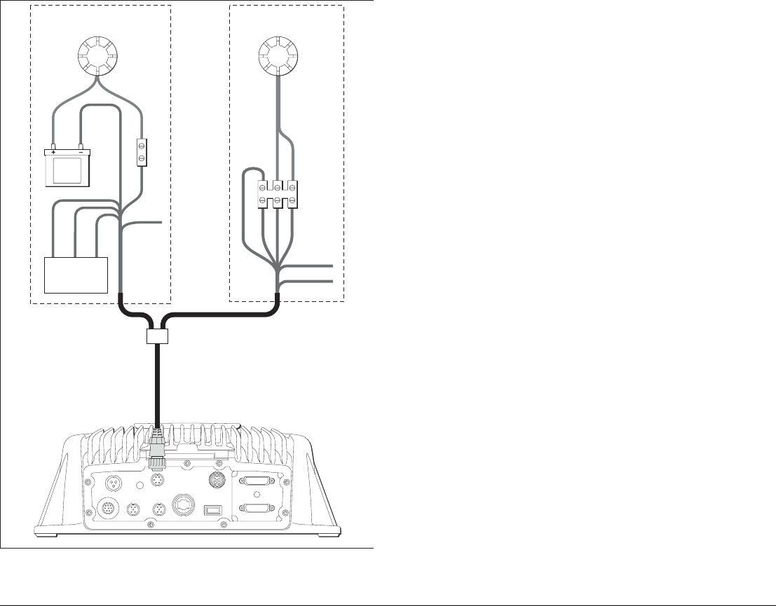
33 Chapter 4: Cables and connections
4.2 Power distribution
Typical distribution
D10145-1
DSM 400
GPSRadar
GPM400 GPM400
+VE bar
Circuit breaker
All GPM400 processors must be
powered from a single breaker.
In line fuse protection must be provided
for each individual power circuit.
-VE bar
GPM400 GPM400
Distribution Panel
Monitor Monitor
Fuses
G-Series Installation & Commissioning 34
Power distribution notes:
• Raymarine recommend that you have a dedicated distribution
panel for your G-Series system.
• All GPM400 processor units must be powered from a single
breaker or switch, with appropriate circuit protection.
• All monitors and ancillary equipment should where possible be
wired to individual breakers.
Sharing a breaker
Where more than 1 piece of equipment shares a breaker you must
provide protection for the individual circuits. E.g. an in-line fuse for
each power circuit
The fuse must be of an appropriate type and rating for the load to
be protected.
Circuit grounding
Grounding notes
• Use a dedicated earthing plate (e.g. dynaplate) in contact with
the water.
• Ground cables may be routed to a common point (e.g. within
the switch panel. With a single (appropriately rated) copper
braid connecting to the earthing plate.
• Use flat tinned copper braid, 30 A rating (1/4 inch) or greater.
Equivalent stranded wire diameter 4mm or greater.
• Keep the length of the earth braid as short as possible.
• Installations using both AC and DC current should have a sepa-
rate ground circuit for each. See Circuit isolation on page 32.
D10164-1
+VE bar
Circuit breaker
FuseFuse
Monitors and ancilliary equipment where
possible be wired to individual breakers.
Where this not possible an inline FUSE
can be used to provide additional portection.
-VE bar
Grounding
The power cable screen and all Ground terminals
MUST be connected to ship’s ground
.
Failure to
connect to ship’s ground may cause it, or other
on-board electronics to function incorrectly
.
No positive ground
The G-Series system is NOT intended for use on
“positive” ground boats. The power input cable
earth screen connections must be connected
directly to the boats ground.
No ground loops
Ground loops may cause galvanic corrosion.
Avoid using the ships structure (metal) as an
earth point, as this could result in ground loops.

35 Chapter 4: Cables and connections
Circuit protection
GPM400 processor
All GPM400 processors must be switched via a single breaker.
General circuit protection
The following loads and protection ratings apply to G-Series dis-
plays and ancillary equipment:
Power cables
• Cable must be of a suitable gauge for the circuit load.
• Each unit should have its own dedicated power cable wired
back to the distribution panel.
• All GPM400 processors should be connected to the same
breaker.
• Power cable must include a separate screen wire.
Number
of
GPM400
units
Supply
voltage
Thermal
breaker
(Overall)
Fuse
(Individual)
1 12 V 10 A 10 A
24 V 5 A 5 A
2 12 V 20 A 10 A
24 V 10 A 5 A
3 12 V 25 A 10 A
24 V 15 A 5 A
4 12 V 35 A 10 A
24 V 20 A 5 A
Equipment Supply
voltage
Thermal
breaker Fuse
G190 marine display 12 V 8 A 12 A
24 V 4 A 6 A
G170 marine display 12 V 8 A 12 A
24 V 4 A 6 A
GVM400 Video Module 12 V 1.2 A 2 A
24 V 1 A 1 A
For other ancillary equipment, refer to the separate installation instructions for
circuit loading and protection information.
Equipment Supply
voltage
Thermal
breaker Fuse

G-Series Installation & Commissioning 36
GPM400 power cables
GVM400 Video Module power cables
G170/G190 Marine monitor power cables:
Length (max) Supply voltage Cable gauge
(AWG)
0-5 m
(0-16.4 ft)
12 V 18
24 V 20
5-10 m
(16.4-32.8 ft)
12 V 14
24 V 18
10-15 m
(32.8-49.2 ft)
12 V 12
24 V 16
15-20 m
(49.2-65.6 ft)
12 V 12
24 V 14
Each unit should have its own dedicated power cable wired back to the distribu-
tion panel.
All GPM400 processors should be connected to the same breaker.
Power cable must include a separate screen.
Length (max) Supply voltage Cable gauge
(AWG)
0-5 m
(0-16.4 ft)
12 V 20
24 V 20
5-10 m
(16.4-32.8 ft)
12 V 20
24 V 20
10-15 m
(32.8-49.2 ft)
12 V 20
24 V 20
15-20 m
(49.2-65.6 ft)
12 V 18
24 V 20
The GVM400 should have its own dedicated power cable wired back to the
distribution panel.
Power cable must include a separate screen.
Length (max) Supply voltage Cable gauge
(AWG)
0-5 m
(0-16.4 ft)
12 V 12
24 V 12
5-10 m
(16.4-32.8 ft)
12 V 9
24 V 9
10-15 m
(32.8-49.2 ft)
12 V 7
24 V 7
15-20 m
(49.2-65.6 ft)
12 V 6
24 V 6
Monitor connection notes:
• Each monitor should have its own dedicated power cable.
• Equipment which is susceptible to noise (such as VHF radios) should not be
wired to the same distribution panel as the monitors. If in doubt the monitors
(or affected equipment) can be wired directly back to the battery/power
source via a dedicated breaker.
Refer to the separate monitor documentation for more details.
Length (max) Supply voltage Cable gauge
(AWG)
37 Chapter 4: Cables and connections
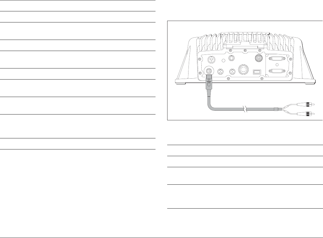
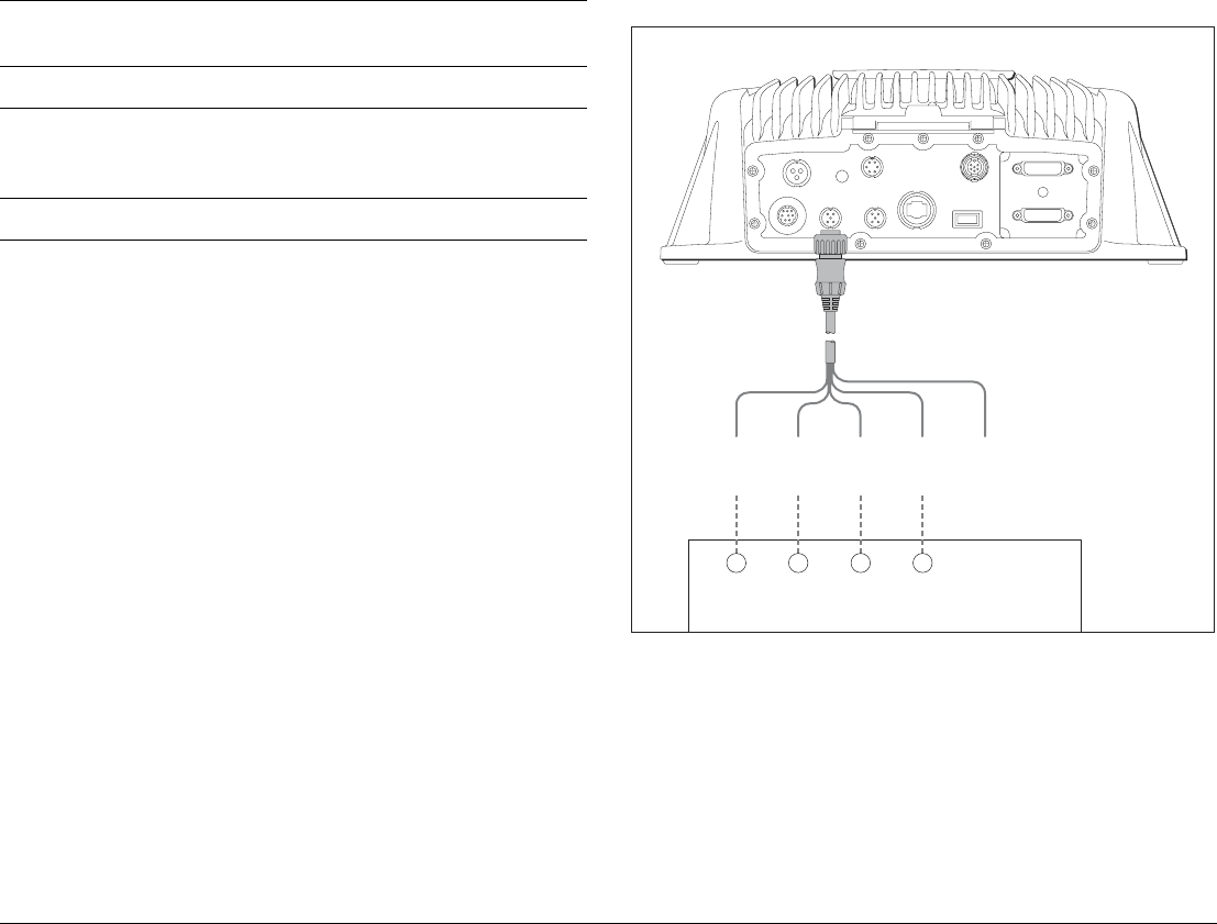
4.3 GPM400 processor
The GPM400 has the following connections:
1. 12/24V Power in (see page 33)
2. Status LED (see page 99)
3. SeaTalk / Alarm output (see page 50)
4. SeaTalkng connection (see page 54)
5. DVI display connection - repeater (see page 38)
6. DVI display connection - master (see page 38)
7. USB connection (for chart and software upgrade only)
8. SeaTalkhs network connection (see page 47).
9. NMEA 0183 connection (see page 51)
10. NMEA 0183 connection (see page 51)
11. Audio output (see page 46)
Maximum quantity of GPM400 units
The G-Series system will support up to 4 GPM400 processors, of
which 1 must be set as the Master GPM.
Master GPM
On a system with more than one GPM400 you must designate one
them as a Master GPM. The SeaTalk and SeaTalkng bus must be
connected to the Master GPM.
Note: The data is passed between multiple GPMs using the
SeaTalkhs network.
See also
• Ensure you record connections to the GPM400 on the schemat-
ic diagram. See Appendix B - Nav Station schematic .
• For a typical SeaTalkhs system see page 19.
• For information on SeaTalkhs cables and connections see
page 47.
D10163-1
S
E
A
T
A
L
K
H
I
G
H
S
P
E
E
D
N
M
E
A
0
1
8
3
2
S
E
A
T
A
L
K
/
A
L
A
R
M
O
U
T
P
O
W
E
R
N
M
E
A
0
1
8
3
1
S
E
A
T
A
L
K
N
G
A
U
D
I
O
MONITOR REPEATER
MONITOR MASTER
43 51
67891011
2
G-Series Installation & Commissioning 38
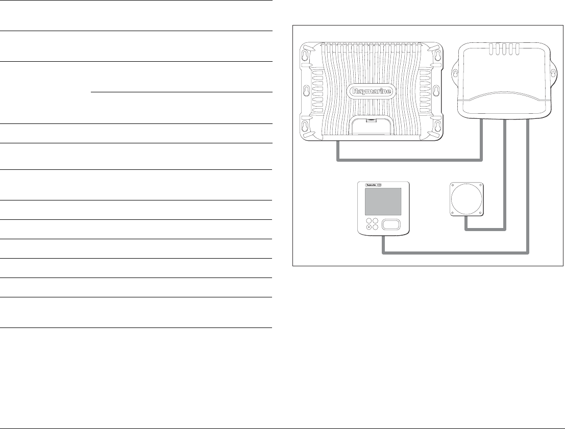
4.4 Monitor connections
Connect the G-Series marine displays to both the GPM400 proces-
sor and SeaTalkhs switch.
Monitors may be connected to the GPM400 using either VGA or
DVI cable.
Repeat displays
Repeat displays (if used) show the same information / page as the
master display. For this reason each display within a Nav Station
must be connected to a different GPM400.
Note: During start-up only the master display will show the boot
sequence and start-up information.
Maximum quantity of monitors
The G-Series system will support up to 8 monitors (2 per GPM400).
CameraCamera
Monitor
GPM 400
Repeat Monitor (optional)
DVI or VGA
DVI or VGA
SeaTalk
hs
SeaTalk
hs
SeaTalkhs
D10074-1
SeaTalk
hs
switch
Composite video
Composite video
D10075-1
Power Cable
DVI
Input
SeaTalkhs
SeaTalkhs
VGA
Input
VGA
input
adaptor
cable
DVI
Input
VGA
Input
Network selector switch
(in UP position)
Monitor
HS switch
GPM 400
OR

39 Chapter 4: Cables and connections
Screen resolution and aspect ratio
Each GPM will output the same screen resolution to all connected
displays.
Therefore where multiple displays are connected to a single GPM
they should have the same aspect ratio and screen resolution. For
example we recommend that wide screen televisions and standard
displays are connected to separate GPMs.
IP Address
When connecting a display to the processor, note its IP address on
your system diagram. You will need to refer to this during the com-
missioning process. (See Appendix B for sample diagrams.)
Selector Switch
Raymarine G-Series displays have a selector switch located by the
SeaTalkhs connector. This must be in the UP position for connec-
tion to the SeaTalkhs network.
3rd party displays
Ensure that any 3rd party (non-Raymarine) displays have electrical
isolation between the video connections and power supply (and
any other 0 V referenced connection). This is to avoid 0 V loops
which can cause interference issues.
Marine display cables
The following cables can be used with marine displays:
Cable Part No Notes
DVI Connection To ensure optimum signal quality
use only Raymarine cables.
5 m (16.4 ft)
DVI to DVI (digital) cable
E06021
10 m (32.8 ft)
DVI to DVI (digital) cable
E06022
VGA To ensure optimum signal quality
use only Raymarine cables.
500 mm (19.69 in)
DVI-VGA converter
E06053 Required for any VGA connec-
tion to the GPM400.
1.5 m (4.9 ft)
VGA cable
R08130
5 m (16.4 ft)
VGA cable
R08174 Supplied with Raymarine
G-Series Marine Displays.
10 m (32.8 ft)
VGA cable
R08296
20 m (65.6 ft)
VGA cable
R08297
Display to SeaTalkhs Required for keyboard control of
display functions.
1.5 m (4.9 ft)
SeaTalkhs cable
E55049
5 m (16.4 ft)
SeaTalkhs cable
E55050
10 m (32.8 ft)
SeaTalkhs cable
E55051
20 m (65.6 ft)
SeaTalkhs cable
E55052
Power
1.5 m (4.9 ft)
Power cable
R08173 Supplied with product
Cable Part No Notes
G-Series Installation & Commissioning 40
See also
• For more detailed installation information refer to the separate
users guide supplied with the display.
• Ensure you record connections to the GPM400 on the schemat-
ic diagram. See Appendix B - Nav Station schematic .
4.5 Keyboard connections
The G-Series Keyboard communicates using the SeaTalkng sys-
tem. It may be connected directly to the backbone (wired) or use a
remote basestation (wireless).
Note: You should have at least one permanently wired keyboard.
In the event that any wireless keyboards are lost, the wired
keyboard can be used to control the system.
Maximum quantity of Keyboards
The G-Series system will support up to 8 keyboards.
Schematic diagram
When connecting a keyboard to the system, record its details on
your system/schematic diagram. You will need this information dur-
ing commissioning. (See Appendix B for sample diagrams.)
Wired keyboard system
Power cable extension Not supplied You may extend the power cable
if required. See page 35.
See Appendix C for other cables and accessories.
Cable Part No Notes
Monitor
Keyboard
D10068-1
SeaTalkng backbone
SeaTalkng spur
SeaTalkng spur
GPM 400
9
WXYZ
8
TUV
7
PQRS
4
GHI
5
JKL
6
MNO
ACTIVE
WPTS
MOB
DATA
MENU
PAGE
.0
2
ABC
3
DEF
1
CANCEL
STANDBY
DODGE PILOT OK
RANGE
OUT
IN
ENTER
41 Chapter 4: Cables and connections
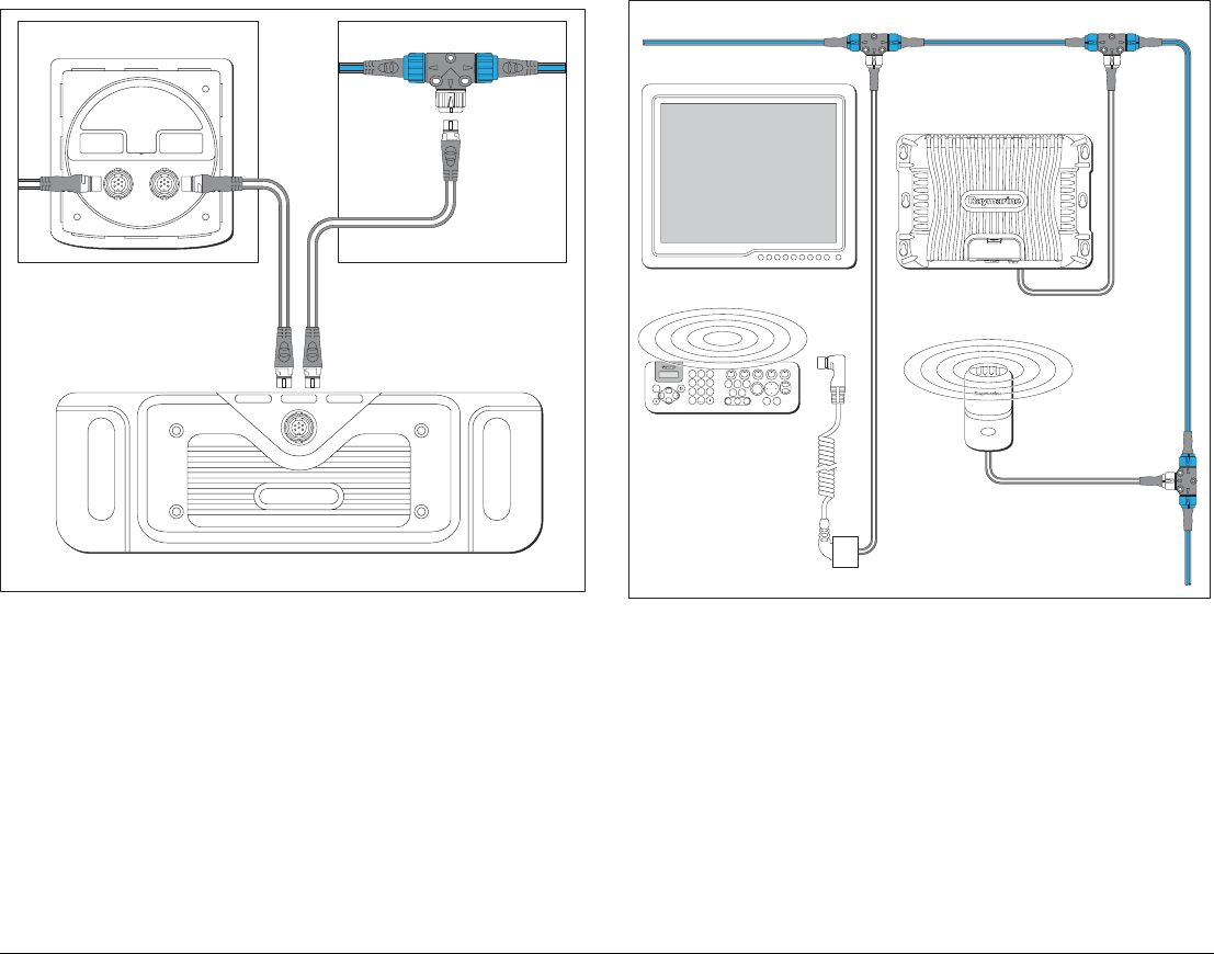
Wired keyboard connection details
For cable part numbers see page 42.
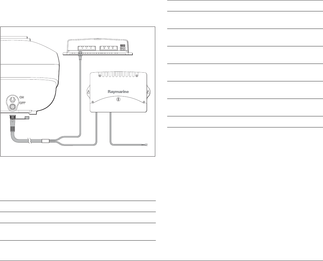
Wireless keyboard system
OR
SeaTalk
ng
instrument, e.g. ST70
SeaTalk
ng
spur
SeaTalk
ng
spur
Keyboard
SeaTalk
ng
backbone
D10070-1
Monitor
Keyboard
SeaTalkng backbone
SeaTalkng spur
SeaTalkng spur
SeaTalkng spur
GPM400
D10069-1
SeaTalkng
charge cable
Basestation
Charge point
9
WXYZ
8
TUV
7
PQRS
4
GHI
5
JKL
6
MNO
ACTIVE
WPTS
MOB
DATA
MENU
PAGE
.0
2
ABC
3
DEF
1
CANCEL
STANDBY
DODGE PILOT OK
RANGE
OUT
IN
ENTER
G-Series Installation & Commissioning 42
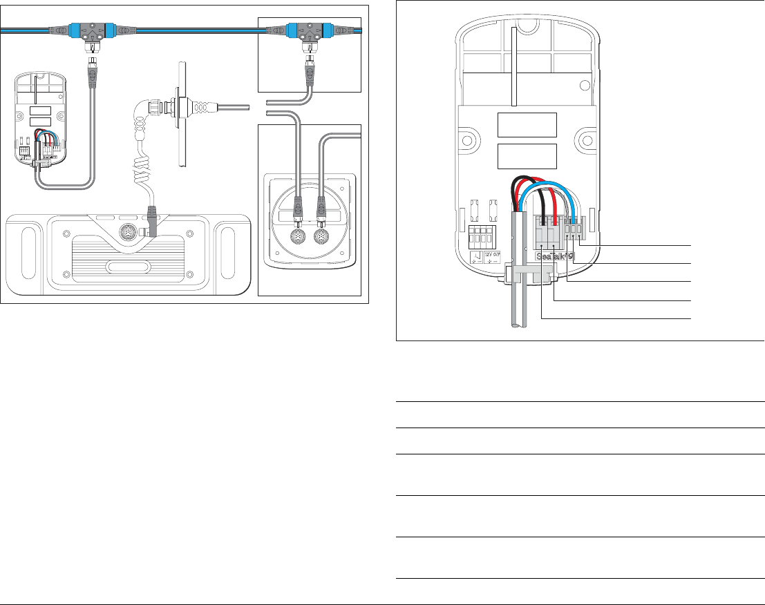
Wireless keyboard connection details
Keyboard cables
The following cables can be used with the Keyboard:
OR
Wireless
basestation
Keyboard
SeaTalk
ng
backbone
Charge
point
SeaTalk
ng
bulkhead
mounting
SeaTalk
ng
spur
SeaTalk
ng
instrument
(e.g. ST70)
D10071-1
Cable Part No Notes
Keyboard to SeaTalkng
400 mm (15.75 in)
SeaTalkng spur cable
A06038
1 m (3.3 ft)
SeaTalkng spur cable*
A06039*Suppled with the keyboard
3 m (9.8 ft)
SeaTalkng spur cable
A06040
D10208-1
Black
Red
Blue
White
Wireless
basestation
SeaTalkng
connection
Screen

43 Chapter 4: Cables and connections
See also
Ensure you record connections to the GPM400 on the schematic
diagram. See Appendix B - Nav Station schematic .
4.6 Video and Entertainment
Video and entertainment is connected and distributed to the
G-Series system using 2 system components:
• GVM400 Video Module
• SeaTalkhs switch.
Note: Video equipment may also be connected directly into the
displays, although this will not be distributed around the
system.
5 m (16.4 ft)
SeaTalkng spur cable
A06041
Wireless basestation to SeaTalkng
1 m (3.3 ft)
SeaTalkng spur cable
(bare ends)
A06043 Included with wireless
basestation.
3 m (9.8 ft)
SeaTalkng spur cable
(bare ends)
A06044
Dashboard / Charging
2.5 m (8.2 ft)
charging cable
R08311 Included with the wireless
upgrade kit.
3 m (9.8 ft)
SeaTalkng bulkhead
mounting cable
R08310
See Appendix C for other cables and accessories.
Cable Part No Notes
G-Series Installation & Commissioning 44
Typical video system
Maximum quantity of GVM400 video modules
The G-Series system will support up to 2 GVM400 video modules.
D10076-1
SeaTalkhs switch
S-Video and Audio
SeaTalkhs
SeaTalkhs
SeaTalkhs
network
DVD
OR
Sat
TV
GVM400 video module
Composite
Composite
Composite
45 Chapter 4: Cables and connections
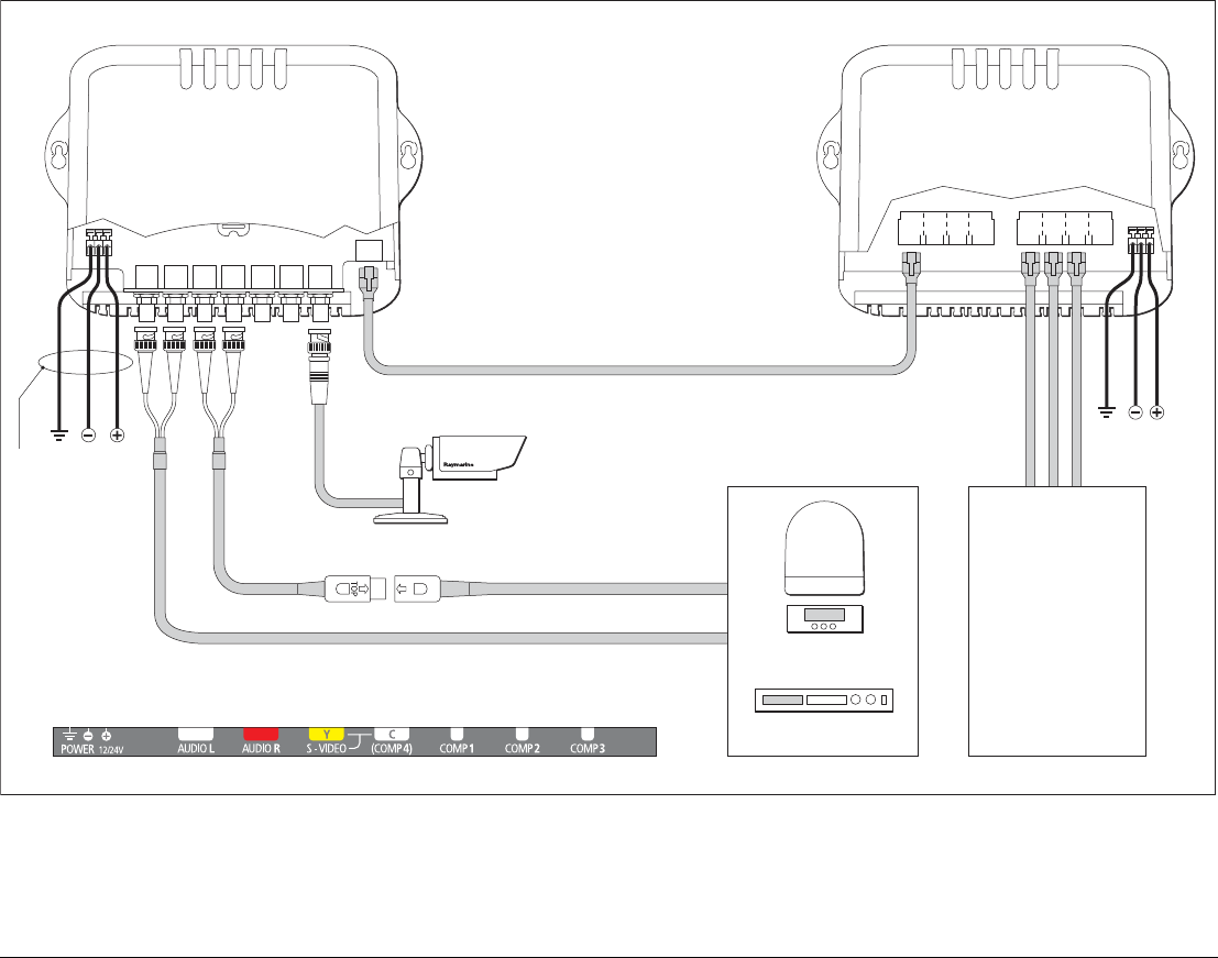
Video / Entertainment connection details
D10077-1
Video module SeaTalkhs switch
SeaTalkhs
G-Series and
SeaTalkhs devices
DVD
OR
Audio
Video module connections
S-Video
Sat
TV
Screened
power cable
Power
supply
Earth
G-Series Installation & Commissioning 46
Video/Entertainment system cables
The following cables are used to connect the GVM400 video
module:
Video output connection
The video output is obtained from the GPM400 processor using
DVI or VGA cables. See Monitor connections on page 38 for
details.
Audio output connection
G-Series audio output is obtained from the GPM400. The following
audio signals are obtained through this output.:
• Entertainment / Audio from the Video processor. (Associated
with the Comp4 or S-Video connection)
• Alarms and other system alerts.
Note: The audio output is line level only and must be connected to
a suitable 3rd party amplifier in order to be heard.
Audio cables
The following cables are available to connect to the audio output:
Cable Part No Notes
S-Video
1.5 m (4.9 ft)
adapter cable
R08274 Included with GVM400.
Audio
1.5 m (4.9 ft)
audio cable
R08275 Included with the GVM400
AV cables N/A Installer to supply suitable cables.
Video and audio equipment should be supplied with appropriate cables to
connect to the G-Series system.
SeaTalkhs Use SeaTalkhs Patch cables.
See page 47
Power Power cables are not included with GVM400.
You must supply appropriate power cables to
suit your system requirements (see page 35).
See Appendix C for other cables and accessories.
Cable Part No Notes
Audio
3 m (9.8 ft)
Audio out cable
R08266 Supplied with GPM400.
15 m (49.2 ft)
G-Series Audio out
cable
R08298
GPM 400
D10190-1
To ship's audio system

47 Chapter 4: Cables and connections
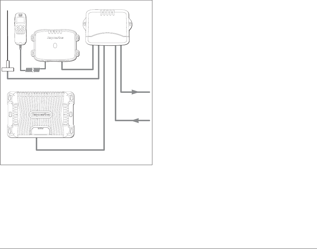
4.7 SeaTalkhs network
The SeaTalkhs network has 2 main purposes:
• Connection of digital devices.
• Networking of G-Series equipment.
For a typical SeaTalkhs system see page 19.
SeaTalkhs devices
The following digital devices communicate via the SeaTalkhs
network:
•SeaTalkhs Switch
The hub of the network, this routes all network traffic.
•GPM400 processors
For sharing data over the network.
•GVM400 Video Module
For video distribution over the G-Series network. See page 43
•Digital radar
•Digital sounder (e.g. DSM400)
For fishfinding applications. Refer to the separate instructions
supplied with the sounder.
•G-Series marine displays (G190, G170 etc.)
To allow control of display functions at the G-Series keyboard.
See page 38
•SR100 Sirius weather/audio receiver (North America only.)
To receive sirius satellite weather and audio services.
See also
For a typical SeaTalkhs system see page 19.
For more details on the connections refer to the separate instruc-
tions supplied with the digital devices and the SeaTalkhs switch.
SeaTalkhs Network cables
All devices are wired individually back to the SeaTalkhs switch
using the following cables:
Cable Notes
SeaTalkhs network
1.5 m (4.9 ft)
SeaTalkhs network
cable
E55049 Network cables are used to connect
the GPM400 to the SeaTalkhs
switch.
5 m (16.4 ft)
SeaTalkhs network
cable
E55050
10 m (32.8 ft)
SeaTalkhs network
cable
E55051
15 m (49.2 ft)
SeaTalkhs network
cable
A62135
20 m (65.6 ft)
SeaTalkhs network
cable
E55052
SeaTalkhs patch
G-Series Installation & Commissioning 48
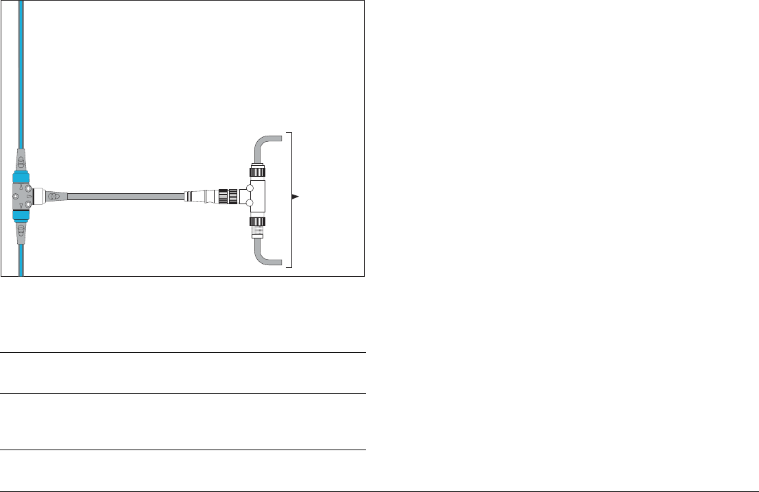
Increasing network capacity
For increased capacity the network may contain multiple SeaTalkhs
switches, connected together using SeaTalkhs network patch
cables.
DSM digital sounder connection
The G-Series system can be used with the following DSM units:
• DSM300
• DSM400
The DSM connects to G-Series system via the SeaTalkhs switch.
Example: DSM400 connection
Maximum quantity of DSM sounders
The G-Series system will support 1 DSM sounder.
See also
For more information refer to the installation guide supplied with the
DSM unit.
1.5 m (4.9 ft)
SeaTalkhs patch cable
E06054 Patch cables are used to connect
the following devices to the
SeaTalkhs switch:
• GVM400 video module
• SeaTalkhs Switch (connecting to
other SeaTalkhs switches).
• G-Series marine displays.
5 m (16.4 ft)
SeaTalkhs patch cable
E06055
10 m (32.8 ft)
SeaTalkhs patch cable
E06056
15 m (49.2 ft)
SeaTalkhs patch cable
A62136
20 m (65.6 ft)
SeaTalkhs patch cable
E06057
Power Power cables are not included with the SeaTalkhs
switch. You must supply appropriate power cables to
suit your system requirements (see page 35).
See Appendix C for other cables and accessories.
Cable Notes
D10201-1
HS switch
SeaTalk HS
DSM400
49 Chapter 4: Cables and connections
Digital radar connection
The digital radar scanner connects to the SeaTalkhs switch using
dedicated digital radar cables
Maximum quantity of Radar scanners
The G-Series system will support up to 2 digital rader scanners.
Digital radar cables
The following cables are used to connect the digital radar scanner:
See also
For more information refer to the installation guide supplied with the
radar scanner.
4.8 GPS Connection
Depending upon your GPS type it may be either connected via
SeaTalk or NMEA 0183.
For SeaTalk connection refer to:
•SeaTalk & Alarm connection on page 50.
• Separate instructions supplied with your GPS unit.
For NMEA 0183 connection refer to:
•NMEA 0183 connections on page 51
• Separate instructions supplied with your GPS unit.
Cable Part No Notes
Digital cable
5 m (16.4 ft)
Digital cable
A55076
HS switch
Radar
D10202-1
Power
VCM100
10 m (32.8 ft)
Digital cable
A55077
15 m (49.2 ft)
Digital cable
A55078
25 m (82.0 ft)
Digital cable
A55079
Digital extension cable Required if you wish to extend
the cable distance.
5 m(16.4 ft)
extension cable
A5080
10 m (32.8 ft)
extension cable
A55081
The maximum cable length including all extensions is 55 m (180 ft)
Cable Part No Notes
G-Series Installation & Commissioning 50
4.9 SeaTalk & Alarm connection
The alarm output and SeaTalk are combined into a single connec-
tor. This includes a 12 V fused power supply.
Alarm output
The alarm output is used to alert the operator to alarms and other
audible warnings.
Note: Alarms are global and as such will be sounded across all
audio and alarm outputs across the system.
SeaTalk connection
The SeaTalk connection allows the G-Series system to receive
data from Raymarine SeaTalk compatible devices such as:
• Autopilot
The G-Series can receive and display autopilot information and
act as a repeat controller. Refer to the separate reference guide
for operation details.
•Instruments
The G-Series can receive and display data received from instru-
ments, such as wind, speed and depth.
•GPS
Required for chart applications.
Master GPM
The SeaTalk bus must be connected to the Master GPM (see
page 37).
Note: SeaTalk connection to other GPMs for the purposes of
redundancy is allowed.
12 V power supply
The SeaTalk connection provides a 12 V supply rated at 125 mA.
This is suitable to supply 1 sounder module.
Note: SeaTalk instruments will usually be powered from a sepa-
rate power supply, e.g from a Raymarine autopilot course
computer. You should not power a SeaTalk bus from more
than one supply.
Alarm Alarm
Red
Black
Red
Black
No other SeaTalk
devices connected
Other SeaTalk
devices connected
Red
Black
Brown
White
White
Brown
Black
Red
Yellow
Drain
SeaTalk/Alarm
Drain
Yellow
Other
SeaTalk
devices
12v
supply
GPM 400
D10144-1
or
51 Chapter 4: Cables and connections
SeaTalk / Alarm output cables
The following cable is used to connect the SeaTalk / Alarm output:
4.10 NMEA 0183 connections
The GPM400 processor has 2 NMEA 0183 connectors.
Dual speed: 38.4 or 4.8 Kbps as required.
These may be used for connection of NMEA compliant devices for
data such as:
•Fastheading, from an autopilot or fastheading sensor.
This is required for Radar target acquisition (MARPA). See
page 52 and your separate autopilot instructions.
•AIS information (for radar target identification).
See page 53 and your separate AIS receiver instructions.
•Other NMEA data (such as 3rd party GPS or autopilot sys-
tems).
For other NMEA device connections refer to the separate man-
ufacturers instructions.
Multiple NMEA devices
You may connect NMEA devices to any GPM400 including the
master GPM. You should only connect 1 device of any particular
type to the G-Series system (including any connected databus or
networked electronics).
For example: Your system should have GPS connected to one
place only. Duplicated GPS data will produce erratic behavior
within the system.
Connection /
Cable Part No Notes
Alarm / SeaTalk
1.5 m (4.9 ft)
SeaTalk/Alarm Out
cable
E55054 Supplied with GPM400
processor.
See Appendix C for other cables and accessories.
GPM 400
D10193-1
Green
-ve
IN
White
+ve
IN
Yellow
+ve
OUT
Brown
-ve
OUT
Screen
(not
connected)
NMEA DEVICE
-ve
OUT
+ve
OUT
+ve
IN
-ve
IN
G-Series Installation & Commissioning 52
NMEA 0183 connection cables
The following cables are used to connect to NMEA 0183 devices.
NMEA 0183 Raymarine cable cores:
Fastheading connection
Fastheading data required for radar target acquisition (MARPA)
may come from either the autopilot or a separate Raymarine Fast-
heading sensor.
Connection /
Cable Part No Notes
1.5 m (4.9 ft)
NMEA 0183 cable
R08004 Supplied with GPM400
processor unit.
Other NMEA
connections
N/A Installer to supply suitable data
cable.
Use a shielded twisted pair cable to mini-
mise interference.
See Appendix C for other cables and accessories.
Function
(at GPM400 processor)
Color Pin no.
NMEA Input (-ve) common Green 1
NMEA Input (+ve) White 2
NMEA Output (+ve) Yellow 3
NMEA Output (-ve) common Brown 4
Not connected Screen 5
Note: Input and outputs are crossed.
Input GPM400 is connected to output at NMEA device and vice versa.
D10191-1
ENTERCANCEL
MENU
GPM 400
NMEA0183
Autopilot
Pilot control head Fluxgate compass
53 Chapter 4: Cables and connections
AIS connection
For more information refer to separate AIS instruction documents.
D10192-1
GPM 400
AIS receiver
VHF radio
VHF antenna
NMEA0183
4.8 (GPS data
to VHF radio)
NMEA0183 4.8
(fast heading)
NMEA0183 (38.4)
G-Series Installation & Commissioning 54
4.11 SeaTalkng connections
The G-Series system will use SeaTalkng to communicate with:
• SeaTalkng instruments (e.g. ST70),
• SeaTalkng autopilots (e.g. ST70 with SPX course computer),
• G-Series keyboard.
SeaTalkng cables
The SeaTalkng system uses the following cables and connections.
SeaTalkng power
The SeaTalkng bus requires a 12 V power supply. This may be
provided from:
• Raymarine equipment witha regulated 12 V supply. (e.g. a
SmartPilot course computer)
• Other suitable 12 V supply. (Note the grounding requirements
for the G-Series system, see page page 34.
Typical SeaTalkng system
Connection /
Cable Notes
Backbone cables
(various lengths)
The main cable carrying data. Spurs from the back-
bone are used to connect SeaTalkng devices.
T-piece connectors Used to make junctions in the backbone to which
devices can then be connected.
Terminators Required at either end of the backbone.
Spur cables Used to connect devices.
Devices may be daisy chained or connected directly
to the T-pieces.
For more information refer to the separate SeaTalkng reference manual.
Keyboard
GPM 400
Autopilot (Course Computer)
12 V / 24 V dc 12 V dc + Data
D10195-1
ENTERCANCEL
MENU
ENTERCANCEL
MENU
Power Supply
9
WXYZ
8
TUV
7
PQRS
4
GHI
5
JKL
6
MNO
ACTIVE
WPTS
MOB
DATA
MENU
PAGE
.0
2
ABC
3
DEF
1
CANCEL
STANDBY
DODGE PILOT OK
RANGE
OUT
IN
ENTER
SeaTalkng backbone
55 Chapter 4: Cables and connections
4.12 NMEA 2000 connections
NMEA 2000 devices are connected using the SeaTalkng bus. The
G-Series system can display data received from NMEA 2000
devices (e.g. for displaying data from compatible engines).
You may connect NMEA 2000 compatible devices using appropri-
ate adaptor cables.
NMEA 2000 cable
The following cable is used to connect the NMEA 2000 devices to
the SeaTalkng bus:
See also
For more information refer to the separate SeaTalkng reference
manual.
Connection /
Cable Part No Notes
1.5 m (4.9 ft)
SeaTalkng to DeviceNet
male
A06046
SeaTalkng
to DeviceNet cable
SeaTalkng backbone
NMEA 2000
equipment
(e.g. engine via
appropriate
manufacturers
interface)
D10599-1

G-Series Installation & Commissioning 56

5
Chapter 5: Installation and mounting
This section gives details for installation and mounting of the core components of the G-Series system. Use
this information when planning and installing your system.
Chapter contents
•5.1 General instructions. Page 58
•5.2 GPM400 Processor module. Page 59
•5.3 G-Series Keyboard. Page 60
•5.5 GVM400 Video Module. Page 66
•5.6 Alarm buzzer. Page 67
See also
• Monitor installation. Refer to the separate instructions supplied with the monitor.
• Peripheral equipment. Refer to the instructions supplied with the individual packs.
• Cabling and connections - Chapter 4: Cables and connections. Page 31.

G-Series Installation & Commissioning 58
5.1 General instructions
Equipment location
When deciding on the location of system components, consider the
following:
• Ignition hazards
• Ventilation
• Mounting surface
• Cable entry
• EMC installation guidelines
Ignition hazards
Ventilation
To ensure adequate airflow:
• Ensure that equipment is mounted in a compartment of suitable
size.
• Ensure that ventilation holes are not obstructed.
• Allow adequate separation of equipment.
Any specific requirements for each system component are provided
later in this chapter.
Mounting surface
Ensure equipment is adequately supported on a secure surface.
Do not mount units or cut holes in places which may damage the
structure of the vessel.
Any specific requirements for each system component are provided
later in this chapter.
Cable entry
Ensure the unit is mounted in a location which allows proper routing
and connection of cables:
• Minimum bend radius of 100 mm (3.94 in).
• Use cable supports to prevent stress on connectors.
EMC installation guidelines
Raymarine equipment and accessories conform to the appropriate
Electromagnetic Compatibility (EMC) regulations. This minimizes
electromagnetic interference between equipment, which could oth-
erwise affect the performance of your system.
Correct installation is required to ensure that EMC performance is
not compromised.
For optimum EMC performance, we recommend that:
• Raymarine equipment and the cables connected to it are:
i. At least 3 ft. (1 m) from any equipment transmitting or cables
carrying radio signals e.g. VHF radios, cables and
antennas. In the case of SSB radios, the distance should be
increased to 7 ft. (2 m).
ii. More than 7 ft. (2 m) from the path of a radar beam. A radar
beam can normally be assumed to spread 20 degrees
above and below the radiating element.
• The product is supplied from a separate battery from that used
for engine start. This is important to prevent erratic behavior
and data loss which can occur if the engine start does not have
a separate battery.
• Raymarine specified cables are used.
• Cables are not cut or extended unless doing so is detailed in the
installation manual.
Potential ignition sources
The equipment in these instructions is NOT
approved for use in hazardous/flammable atmo-
spheres such as an engine room.
59 Chapter 5: Installation and mounting
Remember
Where constraints on the installation prevent any of the above
recommendations:
• Always allow the maximum separation possible between differ-
ent items of electrical equipment.
• This will provide the best conditions for EMC performance for
the installation.
Suppression ferrites
Raymarine cables may be fitted with suppression ferrites. These
are important for correct EMC performance. Any ferrite removed to
facilitate installation must be replaced in the original position imme-
diately after the installation is complete.
• Use only ferrites of the correct type, supplied by Raymarine au-
thorized dealers.
Connections to other equipment
If Raymarine equipment is to be connected to other equipment
using a cable not supplied by Raymarine, a Raymarine suppres-
sion ferrite MUST always be attached to the cable near the
Raymarine unit.
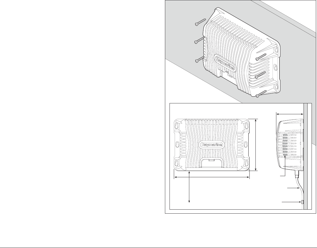
5.2 GPM400 Processor module
D10100-1
Minimum radius
bend of cable
(100mm)
Minimum ventilation
clearance of XXX mm
around total perimeter Cable clip
Air vents
335 mm (13.2 in)
230 mm (9.0 in)
125 mm (4.92 in)

G-Series Installation & Commissioning 60
Mounting and environment
The following conditions apply:
• Do NOT install near sources of heat or vibration (e.g. engine).
• The unit is NOT designed for use in a sealed enclosure. Access
to the unit is required, e.g. for chart updates.
• Must be mounted on a vertical surface. Sides and top must be
level.
• Mounting surface must be firm, secure and capable of support-
ing the weight of the unit.
• Install below decks in a dry area.
• Install the unit well away from potential sources of ignition.
Mounting clearances
Allow the following clearances from other equipment and surfaces.
Cables
• Minimum bend radius of 100 mm (3.94 in)
• All cables must be secured within 150 mm (5.91 in) of the unit.
This will prevent undue strain on the connectors.
See also
Ensure you record connections to the GPM400 on the schematic
diagram. See Appendix B - Nav Station schematic.
For connection details, see page 31.
5.3 G-Series Keyboard
The Keyboard can be installed for 2 different types of use:
• Wired operation (flush mounted).
• Wireless operation, using the wireless upgrade kit and
SeaTalkng basestation.
Note: You should have at least one permanently wired keyboard.
In the event that any wireless keyboards are lost, the wired
keyboard can be used to control the system.
Side Distance
Top 100 mm (3.94 in)
Left 100 mm (3.94 in)
Right 100 mm (3.94 in)
Bottom To allow cable entry
Front 150 mm (5.91 in)
61 Chapter 5: Installation and mounting
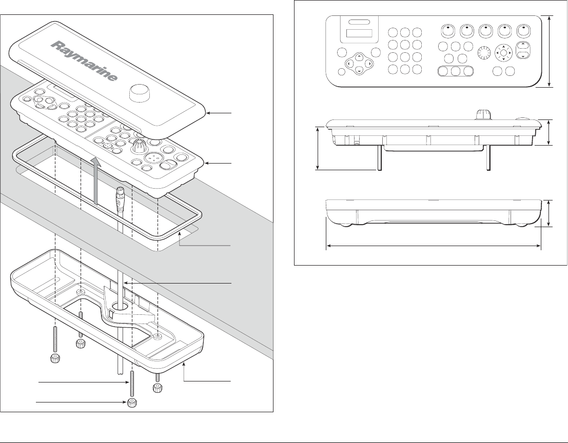
Wired operation - flush mounted
Mounting arrangement
Dimensions
Mounting and environment
• The keyboard is suitable for mounting both above and below
decks. It is waterproof to CFR-46 standard.
• Use the cutting template provided with the keyboard.
• Connect cable into keyboard before clamping in place.
The following conditions apply:
• Do NOT install near sources of heat. (e.g. engine).
• Install the unit well away from potential sources of ignition.
D10101-1
G-Series keyboard
Sun cover
Keyboard
Panel seal
(adhesive
side up)
SeaTalk NG
cable
Stud (x4)
Finger
nut (x4)
Rear clamp
assembly
D10226-1
297 mm (11.69 in)
98 mm (3.85 in)
35 mm (1.38 in)
59.8 mm (2.35 in)
minimum clearance
46 mm (1.81 in)
G-Series Installation & Commissioning 62
Cables
• Minimum bend radius of 100 mm (3.94 in).
See also
Ensure you record your keyboard details on the schematic dia-
gram. See Appendix B - Nav Station schematic.
Wireless upgrade kit
Allows wireless operation of the keyboard.
Mounting and environment
• The should be within sight of G-series monitors. This will allow a
keyboard to operate the system whilst on charge.
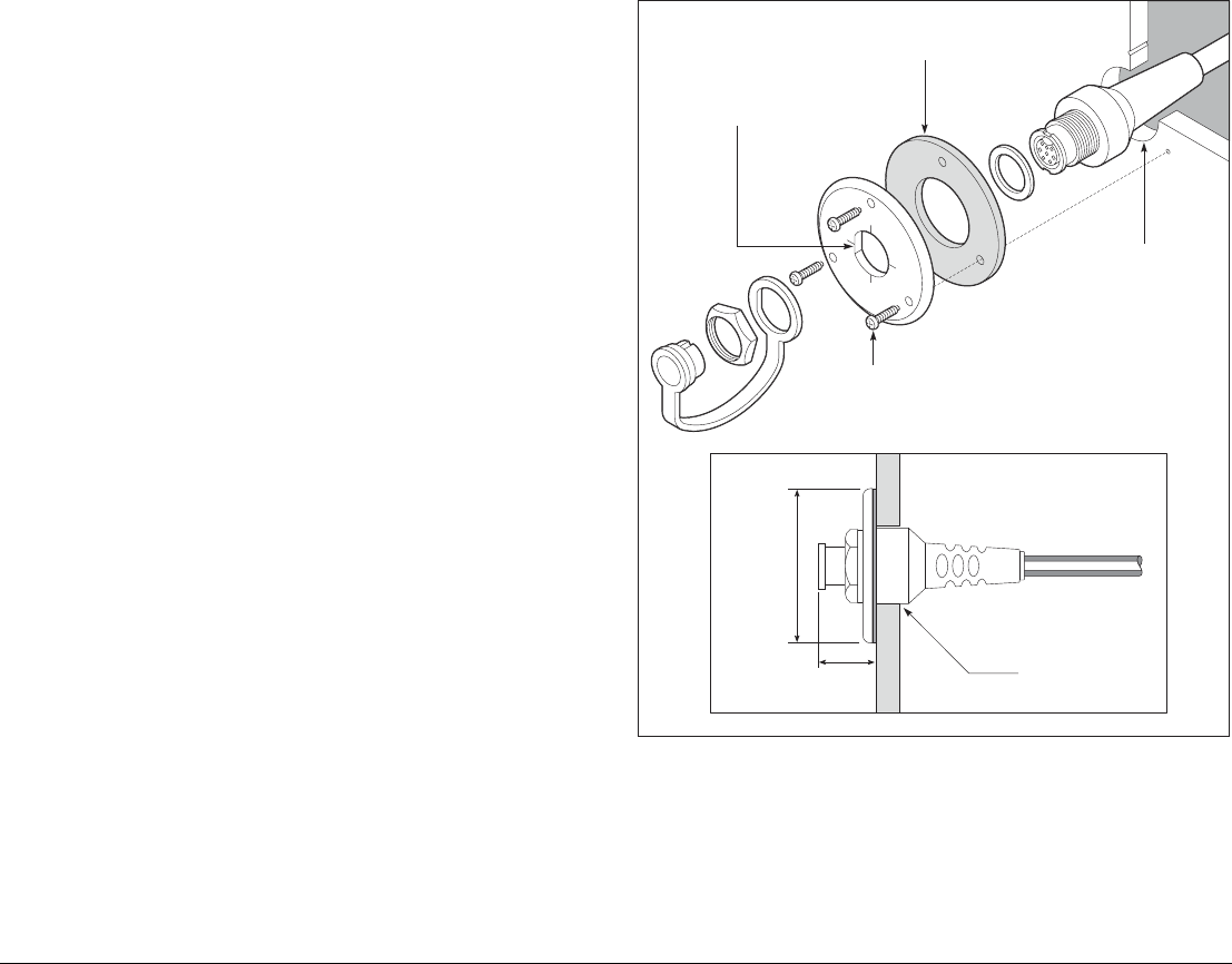
1. Install charge point.
Ensure flat edge is located to
left side for correct orientation
Note: Remove protective cover
from each side of gasket
No.4 x 3/8"screw
Cut 25 mm
diameter hole
25 mm
diameter hole
D10161-1
25 mm
(1 in)
49 mm (2.6 in)
63 Chapter 5: Installation and mounting
2. Fit splash cover. 3. Fit the battery, taking care to avoid contamination of the cover
seal.
D10162-1
D10518-1
G-Series Installation & Commissioning 64
4. Fit the rear cover.
5. For charging and wired operation use the cable provided
Note: The keyboard should be charged for 6 hours before use.
Wireless basestation
Required for wireless operation of the keyboard.
D10189-1
66 mm (2.6 in)
117 mm (4.61 in)
36 mm (1.42 in)