Flir BelgiumBA STNGB Low-power (unlicensed) wireless device for leisure User Manual 87070 1 GSeries Install Comm
Raymarine UK Ltd. Low-power (unlicensed) wireless device for leisure 87070 1 GSeries Install Comm
Contents
- 1. Gseries Reference Part 1
- 2. Gseries Reference Part 2
- 3. Gseries Installation Part 1
- 4. Gseries Installation Part 2
- 5. Gseries Base Station
Gseries Installation Part 2
65 Chapter 5: Installation and mounting
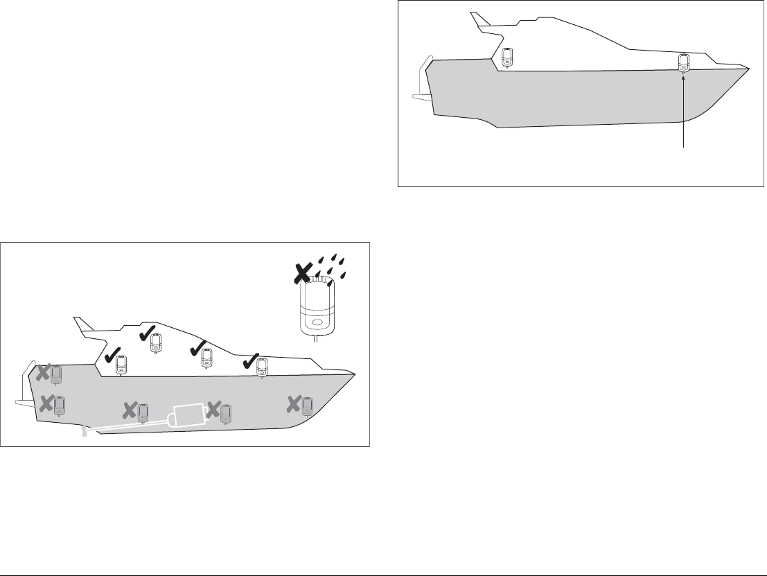
Mounting and environment
The following conditions apply:
• You must perform a site survey to find an appropriate location
and ensure good wireless reception around the boat.
• Do NOT install near sources of heat or vibration. (e.g. engine).
• Install in a dry area as high on the vessel as possible.
• Mount on a vertical surface.
• Install the unit well away from potential sources of ignition.
• Mount at least 1 m (3 ft) away from devices which may be af-
fected by radio transmission (e.g. compass)
Site survey (wireless coverage)
You will need to survey the wireless coverage to ensure that wire-
less devices can operate around the vessel.
Repeat basestation
A repeat basestation may be used to optimize wireless coverage.
Note: Only the master basestation is connected to SeaTalkng. The
repeat basestation requires a power connection only.
5.4 G-Series Monitors
To install your monitor refer to the separate instructions provided.
See also
Ensure you record your monitor details on the schematic diagram.
See Appendix B - Nav Station schematic.
Fit Base Station as high up as possible, in a dry location
D10205-1
Note: Only the master basestation is connected to SeaTalk
ng
.
The repeat basestation requires a power connection only.
D10207-1
G-Series Installation & Commissioning 66
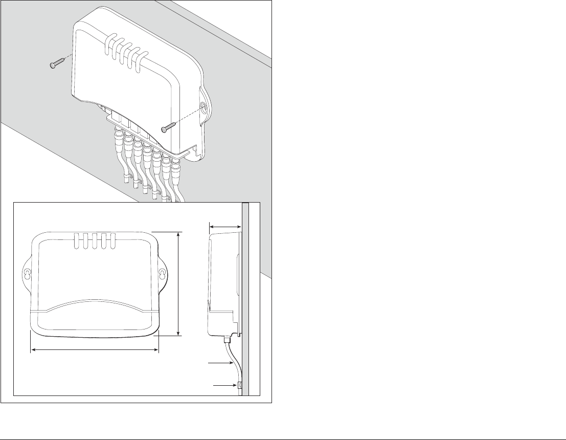
5.5 GVM400 Video Module Mounting and environment
• Mount below decks in a dry area
• Install on a vertical surface.
• Do NOT mount near sources of heat or vibration. (e.g. engine)
• Install well away from potential sources of ignition.
Cables
• Minimum bend radius of 100 mm (3.94 in).
• Power cable should be fixed to the plastic case using the cable
tie provided.
• All video / data cables must be secured within 150 mm (5.91 in)
of the unit using a suitable cable clip. This will prevent undue
strain on the connectors.
D10197-1
Minimum
radius bend
of cable
(100mm)
Cable clip
170 mm (6.7 in)
237 mm (9.33 in)
56 mm
(2.2 in)
67 Chapter 5: Installation and mounting
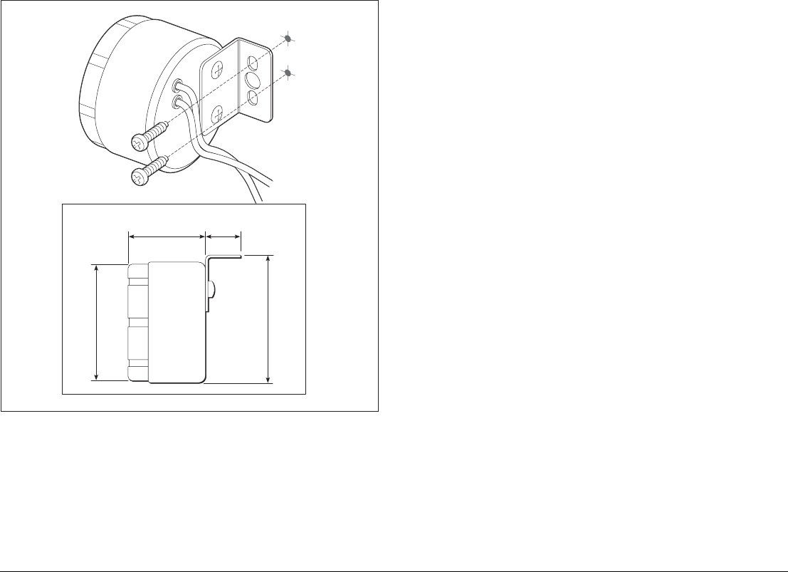
5.6 Alarm buzzer
The alarm is used to alert the operator to alarms and other audible
warnings.
Mounting and environment
• Mount below decks in a dry area
• Install on a vertical surface.
• Do NOT mount near sources of heat or vibration. (e.g. engine)
• Install well away from potential sources of ignition.
D10203-1
38 mm
(1.5 in)
60 mm (2.36 in) diameter
60 mm (2.5 in)
18 mm
(0.7 in)

G-Series Installation & Commissioning 68

6
Chapter 6: Initial test
This section gives details for the initial tests and checks to be carried out once installation is complete.
Chapter contents
• Turn on breakers on page 70
• Marine monitor checks on page 70
• Keyboard checks on page 70
• GPM400 processor checks on page 70
• GVM400 video processor checks on page 70
• SeaTalkhs switch on page 70
See also
For help with diagnosing and rectifying faults, refer to Chapter 9: Troubleshooting.
Before powering up
Before proceeding with the power on test of your system please ensure that:
• Radar and all ancillary equipment has been installed and connected in accordance with the manufactur-
ers instructions.
• All G-Series equipment has been installed and connected in accordance with the G-Series installation
instructions.

G-Series Installation & Commissioning 70
6.1 Power up test
It is advisable to perform an initial power-up test to help ensure that
the system is wired correctly.
Perform the following initial checks before proceeding to the com-
missioning stage:
Turn on breakers
Turn on the power to the equipment at the distribution panel:
1. Monitors and ancillary equipment.
2. GPM400 processors.
Power up sequence
Power up the monitors first to allow the boot sequence and start-up
information to be shown at master monitors.
Check system:
Wait for 2 minutes whilst the boot sequence is completed, then
check each of the following:
• Monitors
• Keyboards
• GPM400 processors
• GVM400 Video Modules
• SeaTalkhs Switch
• DSM sounder module. (refer to separate instructions supplied
with the DSM)
Marine monitor checks
You will need to select the appropriate input on each monitor.
On a G-Series marine monitor:
• Press the power key (if required)
• Press the Left/Right arrow keys to scroll through the inputs.
On a healthy system all monitors will:
• show the G-Series set-up wizard screen on the appropriate in-
put channel.
Note: Only the master monitors will show the initial boot
sequence. The repeat monitors may not begin to operate
until the system has ran through its start-up sequence
(approximately 2 minutes after power on).
Keyboard checks
You can check that each keyboard is correctly connected by look-
ing at its LCD monitor.
On a healthy system all keyboards will:
• Display the message “NOT ASSIGNED”.
GPM400 processor checks
Check that each GPM is correctly connected by looking at its LED
(found next to the SeaTalk/alarm output).
On a healthy GPM400:
• LED will flash Green.
For a full LED status listing see page 99.
GVM400 video processor checks
Check that each GPM is correctly connected by looking at its LED
(found next to the SeaTalk/alarm output).
On a healthy GVM400:
• LED will flash Green.
For a full LED status listing see page 100.
SeaTalkhs switch
Use this to check the status of your SeaTalkhs network connections.

71 Chapter 6: Initial test
On a healthy SeaTalk Switch:
• Each connected channel will have one flashing and one steady
green LED.
For a full LED status listing see page 98.

G-Series Installation & Commissioning 72
7
Chapter 7: Initial Setup
This chapter provides information for the initial setup of a new system
Chapter contents
• 7.1 Power up the system on page 74
• 7.3 Select Master GPM on page 75
• 7.2 First time configuration on page 74
• 7.4 Configure Nav Stations on page 77
• 7.5 Assign Keyboards on page 78
Schematic diagram
You will need details of the equipment connections and serial numbers. You should have entered these onto
the Nav Station schematic diagrams during the installation.
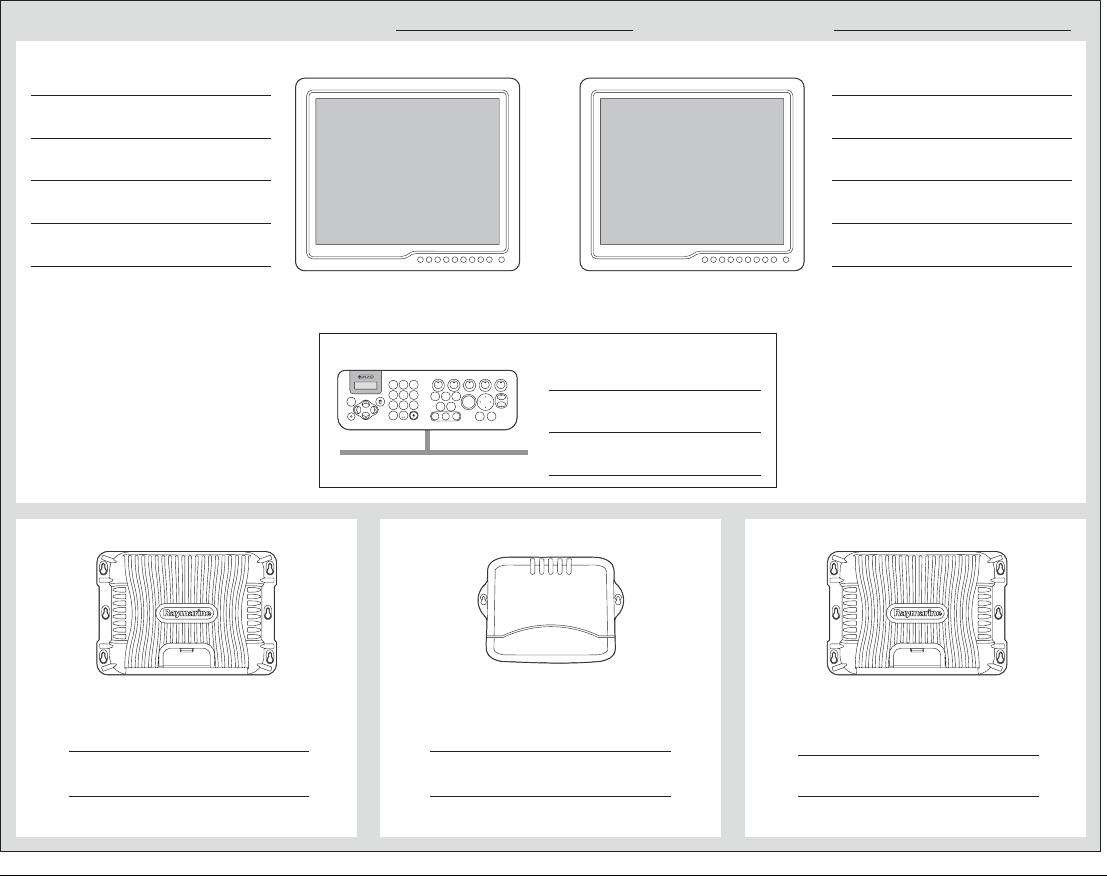
Nav station information Nav station name Nav station location
D10029-1
Display 1 Display 2 (if applicable)
Keyboard
GPM400 processor
9
WXYZ
8
TUV
7
PQRS
4
GHI
5
JKL
6
MNO
ACTIVE
WPTS
MOB
DATA
MENU
PAGE
.0
2
ABC
3
DEF
1
CANCEL
STANDBY
DODGE PILOT OK
RANGE
OUT
IN
ENTER
SeaTalkng
Serial number
Location
Wireless (delete as appropriate)
YES / NO
Master GPM (delete as appropriate)
YES / NO
Master GPM (delete as appropriate)
YES / NO
SeaTalkhs (delete as appropriate)
SeaTalkhs switch
Name
Location
IP address (When on SeaTalkhs only)
Video connection (delete as appropriate)
DVI / VGA
YES / NO
SeaTalkhs (delete as appropriate)
Name
Location
IP address (When on SeaTalkhs only)
Video connection (delete as appropriate)
DVI / VGA
YES / NO
Serial Number
Location
Serial number
Location
GPM400 processor
Serial number
Location
Bridge - Right
BridgeBridge
10-2-0-14
-
-
-
-
-
10-2-0-2
Bridge - Left
1006021 1006024
Left (switch cupboard) Right (switch cupboard)
02070016
Bridge
-
-
Bridge nav Bridge

G-Series Installation & Commissioning 74
7.1 Power up the system
Before powering up
Before proceeding with the power on test of your system please
ensure that:
• Radar and all ancillary equipment has been installed and con-
nected in accordance with the manufacturers instructions.
• All G-Series equipment has been installed and connected in ac-
cordance with the G-Series installation instructions.
Turn on breakers
Turn on the power to the equipment at the distribution panel.
1. Monitors and ancillary equipment
2. GPM400 processors.
Power up sequence
Power up the monitors first to allow the boot sequence and start-up
information to be shown at master monitors.
See also
For information on repeat / master monitors see page 38.
7.2 First time configuration
There is an automatic menu sequence when you set up the system
for the very first time (i.e. for systems which do not yet have any
Nav Stations configured). This will automatically display the appro-
priate menus at power up, to help you to configure your Nav
Stations.
Note: First time configuration must be done at a monitor
connected to the master GPM (see page 75).
Nav Station
A Nav Station is a group of monitors, GPM processors and Key-
boards. This provides a location from where users can view and
control the G-Series system.
First time configuration, automatic sequence
Select Master GPM
•To set the Master GPM on page 76
Create Nav Station
•To create a new Nav Station on page 77
•To assign monitors to a Nav Station on page 77
Assign Keyboards
•Assign Keyboards on page 78
Appropriate set-up menus will automatically appear on the monitor.
75 Chapter 7: Initial Setup
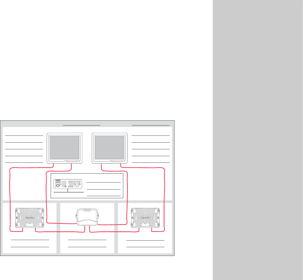
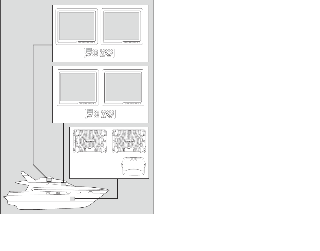
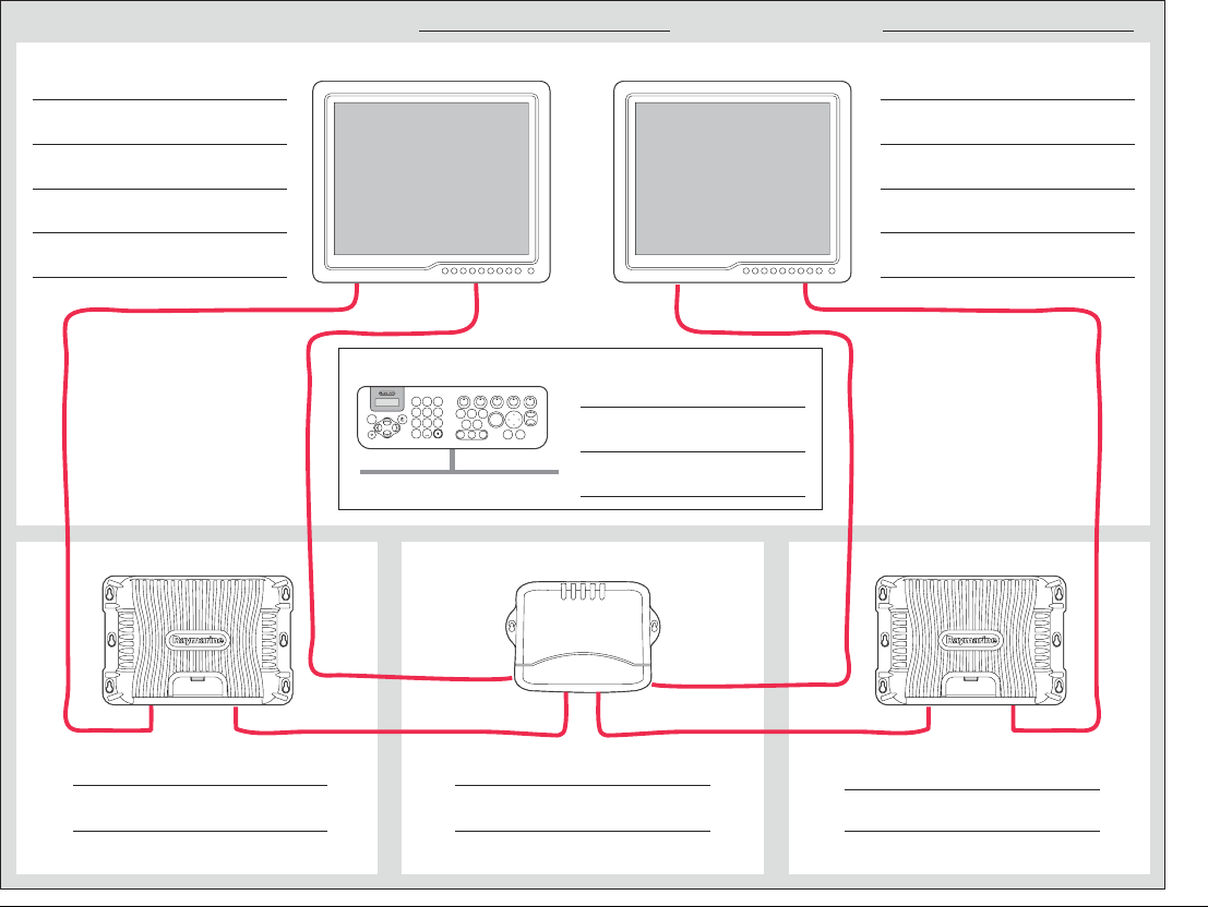
Typical Nav station arrangement
Each display within a Nav Station must be connected to a different
GPM400. This is because the master and repeat displays con-
nected to any single GPM400 will both show the same information
or page.
See also
For more information on nav station connections, see Chapter
2: Typical systems.
7.3 Select Master GPM
The GPM400 master handles the data from the marine electronics
installed around the boat. It receives data (e.g. via SeaTalkng) and
transmit this around the G-Series system via the SeaTalkhs
network.
Note: The initial set up should be done at a monitor connected to
the master GPM. See page 74.
D10239-1
9
WXYZ
8
TUV
7
PQRS
4
GHI
5
JKL
6
MNO
ACTIVE
WPTS
MOB
DATA
MENU
PAGE
0
2
ABC
3
DEF
1
CANCEL
STANDBY
DODGE PILOT OK
RANGE
OUT
IN
ENTER
9
WXYZ
8
TUV
7
PQRS
4
GHI
5
JKL
6
MNO
ACTIVE
WPTS
MOB
DATA
MENU
PAGE
0
2
ABC
3
DEF
1
CANCEL
STANDBY
DODGE PILOT OK
RANGE
OUT
IN
ENTER
Nav Station 1
(Flybridge)
Nav Station 2
(Bridge)
Below decks components
(GPM400, GVM400 etc..)
G-Series Installation & Commissioning 76
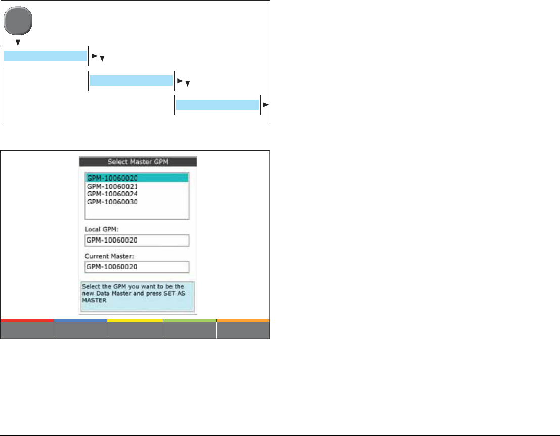
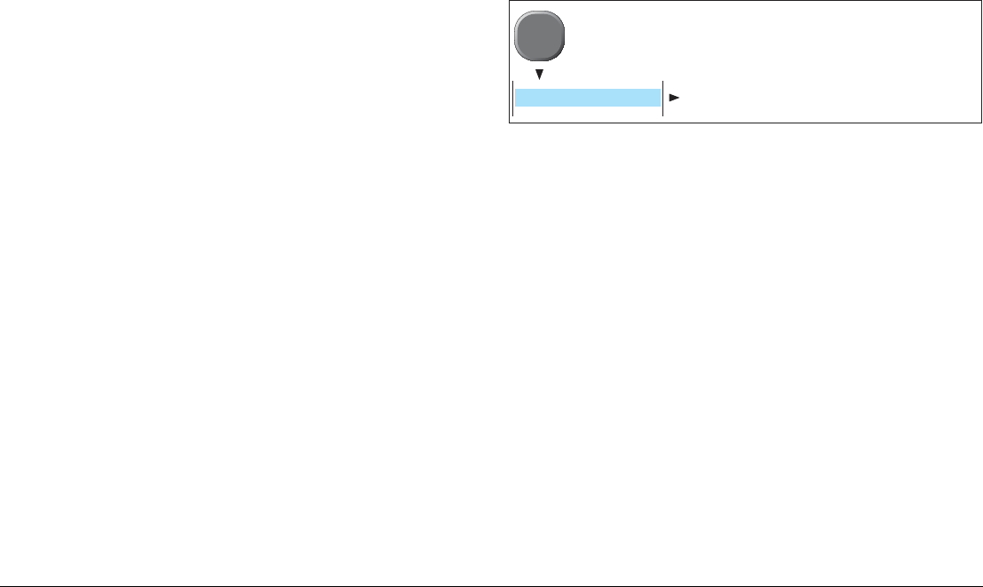
To open the Set Master GPM menu:
Select Master GPM - menu and soft keys
•GPM-XXXXXXXXX
The available GPMs are listed by serial number. Cross refer
these with the Serial numbers on your Nav Station schematic
diagrams.
•Local GPM
Indicates the GPM to which the monitor is physically connected.
•Current Master
This is the GPM currently set at the master.
To set the Master GPM
1. Select the appropriate GPM from those displayed.
2. Press the SET AS MASTER softkey.
To identify the correct GPM
If you are unsure of which GPM to select, press the
DISCOVER GPM softkey to show a message on every monitor
which identifies the GPM to which it is connected.
D10334-1
MENU
SYSTEM SETUP
SYSTEM CONFIGURATION
SET MASTER GPM
SET AS MASTER
D10335-1
77 Chapter 7: Initial Setup
7.4 Configure Nav Stations
For a definition of a Nav station see First time configuration on
page 74.
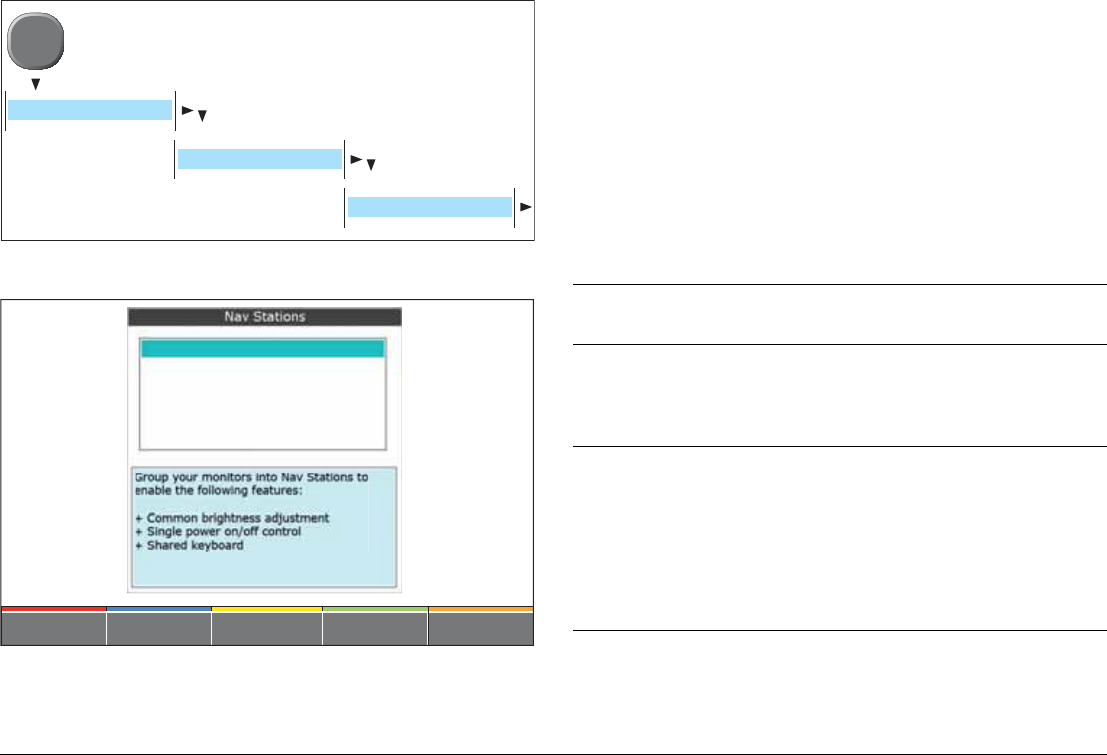
To open the Configure Nav Stations menu:
Nav Stations - menu and soft keys
To create a new Nav Station
from the Configure Nav Stations menu:
1. Press CREATE NAV STATION softkey/
2. Enter the name for the Nav Station.
i. Press SELECT NAME to select from the list of pre defined
names. OR
ii. Press EDIT NAME to use a custom name.
3. Press OK when complete.
To assign monitors to a Nav Station
from the Configure Nav Stations menu:
1. Select the appropriate Nav Station from those displayed
2. Press ASSIGN MONITORS.
3. Select the monitors to be added.
i. Press ADD RAY Monitor to select from the Raymarine
monitors connected to the system. OR
ii. Press ADD OTHER MONITOR to select a non Raymarine
monitor.
4. Enter the appropriate information for the monitor type selected.
D10336-1
MENU
SYSTEM SETUP
SYSTEM CONFIGURATION
CONFIGURE NAV STATIONS
DELETE NAV STSTIONCREATE NAV STATIONASSIGN MONITORS... EDIT NAME
D10337-1
Assign monitors
Information required
Monitor
type(s)
Name
• Press SELECT NAME to select from the list of pre
defined names. OR
• Press EDIT NAME to use a custom name.
ALL
GPM
From the list displayed, select the GPM to which the
monitor is connected.
•DISCOVER GPM
If you are unsure of which GPM to select, press the
DISCOVER GPM softkey to show a message on
every monitor which identifies the GPM to which it is
connected.
ALL
G-Series Installation & Commissioning 78
To identify the correct monitor
Softkeys are provided to help you identify the correct monitor.
•DISCOVER IP
If you are unsure of which monitor to select, press this softkey
to identify the IP address of each monitor.
•IDENTIFY MONITOR
You can confirm that the correct monitor has been assigned by
pressing this softkey. The selected monitor will then display its
OSD menus, allowing it to be identified.
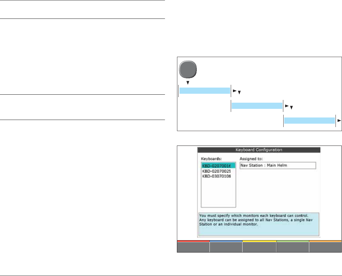
7.5 Assign Keyboards
Introduction
You must assign each G-Series Keyboard to control a Nav station
or an individual monitor.
To open the Assign Keyboards menu:
Keyboard Configuration - menu and soft keys
•KBD-XXXXXXXXX
The available Keyboards are listed by serial number. Cross re-
IP Address
From the list displayed, select the IP address of the
monitor being assigned.
•DISCOVER IP
If you are unsure of which monitor to select, press this
softkey to identify the IP address of each monitor.
•IDENTIFY MONITOR
You can confirm that the correct monitor has been
assigned by pressing this softkey. The selected
monitor will then display its OSD menus, allowing it to
be identified.
RAY monitors only
Input
Select the monitor input to which the G-Series cable is
connected (e.g. VGA 1)
RAY monitors only
Assign monitors
Information required
Monitor
type(s)
D10338-1
MENU
SYSTEM SETUP
SYSTEM CONFIGURATION
ASSIGN KEYBOARDS
ASSIGN TO MONITORASSIGN TO NAV STATION
D10339-1

79 Chapter 7: Initial Setup
fer these with the Serial numbers on your Nav Station
schematic diagrams.
•Assigned to
Shows the assignment of the selected keyboard.
To assign a Keyboard to a Nav Station
from the Assign Keyboards menu:
1. Select the desired keyboard from those displayed.
2. Press ASSIGN TO NAV STN.
Then either:
i. Select from the list of available Nav Stations. OR
ii. Press the ASSIGN TO ALL NAV STNS softkey.
3. Press OK when complete.
To assign a Keyboard to an individual monitor
from the Assign Keyboards menu:
1. Select the desired keyboard from those displayed.
2. Press ASSIGN TO MONITOR.
3. Select from the list of available Monitors.
4. Press OK when complete
To identify the correct keyboard
If you are unsure of which keyboard to select, press the
IDENTIFY KEYBOARD softkey to show a message on the monitor
to identify the keyboard being used.

G-Series Installation & Commissioning 80

8
Chapter 8: Commissioning
This chapter provides information for the commissioning of a system once the initial setup is complete.
Chapter contents
• 8.1 Language setting on page 82
• 8.2 Compass heading setup on page 82
• 8.3 Radar setup on page 83
• 8.4 GPS checks on page 85
• 8.5 Fishfinder checks on page 86
• 8.6 Set up video on page 87
• 8.7 NMEA 0183 on page 88
• 8.8 Data checks on page 89
See also
For details of how to operate the G-Series system or general navigation of the menus and pages, refer to the
separate user reference guide.
G-Series Installation & Commissioning 82
8.1 Language setting
The system will operate in the following languages:
To select a language:
Select the required language from those displayed.
8.2 Compass heading setup
The G-Series system provides options to set up a Raymarine
compass.
Note: If the compass is connected to a Raymarine autopilot, you
should calibrate the compass heading using the autopilot
controller, and proceed to the Radar setup (page 83).
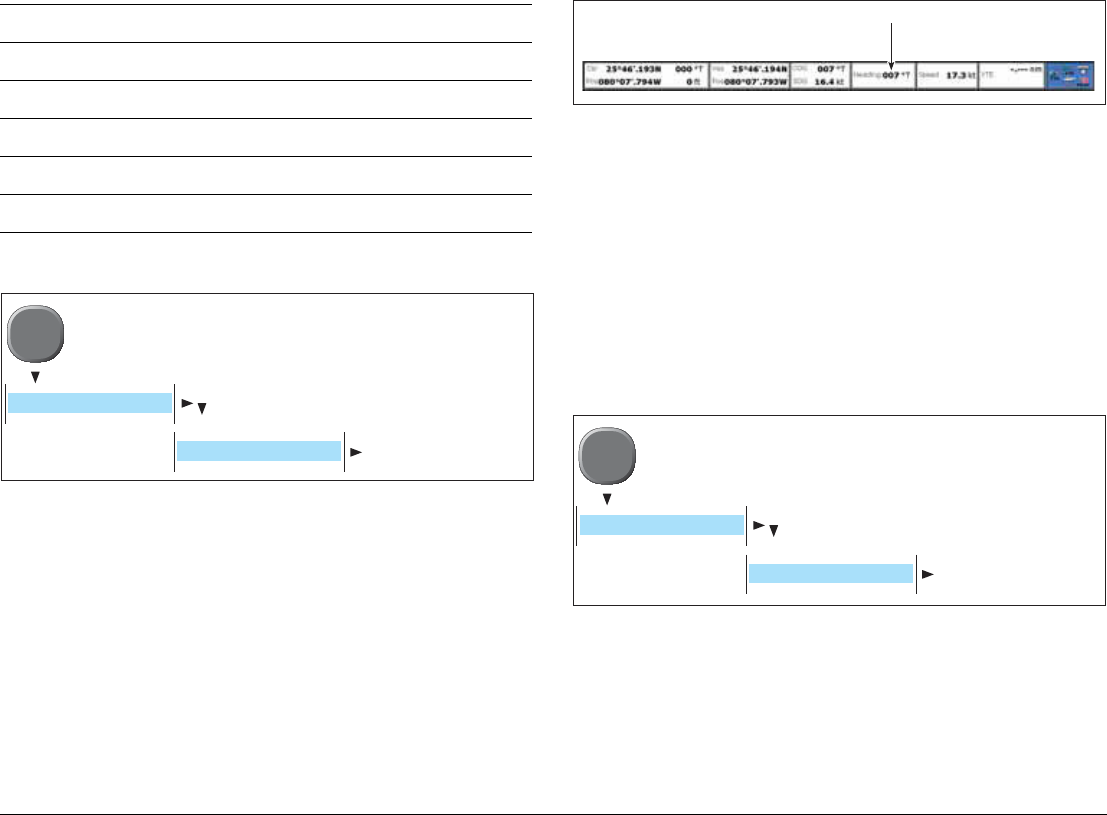
Check heading
Provided that the system has a compass connected, the compass
heading is displayed in the data bar at the top of the screen:
If no heading is displayed this could indicate a problem with the
autopilot or compass connection. See Chapter 9:
Troubleshooting. Page 91 for more information.
Linearize (swing) the compass
If your system has a Raymarine compass (e.g ST80 or Fasthead-
ing sensor) which is not connected to an autopilot system, then you
will need to linearize (swing) the compass using the G-Series
system.
To linearize your compass:
1. Once you have selected LINEARIZE COMPASS, follow the on-
screen instructions.
2. When instructed to align heading, press the ALIGN HEADING
soft key and then turn the rotary control one click at a time to
fine tune the heading.
English (US) English (UK) Chinese
Danish Dutch Finnish
French German Greek
Icelandic Italian Japanese
Korean Norwegian Portuguese
Russian Spanish Swedish
D10340-1
MENU
SYSTEM SETUP
LANGUAGE
D10351-1
Compass Heading
D10349-1
MENU
COMPASS SETUP
LINEARIZE COMPASS
83 Chapter 8: Commissioning
8.3 Radar setup
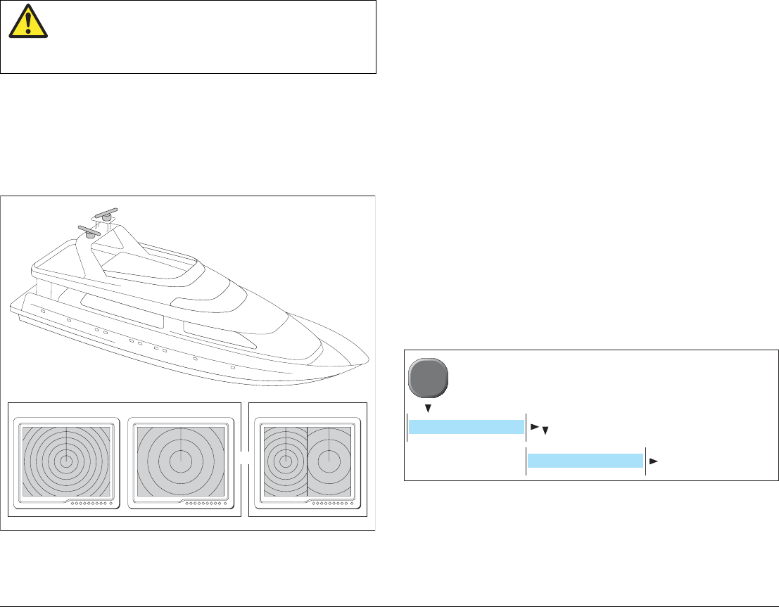
2 scanner systems
The system may have 2 digital scanners connected. You can select
the scanner to be used for each radar window.
For 2 scanner systems you must repeat the instructions in this
(Radar setup) section, once for each scanner.
Initialize radar and set to transmit
You will need to:
• Initialize the radar
• Select a scanner (2 scanner systems only)
• Set radar to transmit
To initialize the radar
Select a Radar page by either:
i. Press the PAGE key to select from the current page set.
OR
ii. Press and hold the PAGE key to select from all available
pages.
The Radar scanners will now initialize in standby mode, this pro-
cess will take approximately 70 seconds.
If the radar fails to initialize, refer to Chapter 9:
Troubleshooting. Page 91.
To assign scanners (2 scanner systems only)
For 2 scanner systems you must select which scanner is to be used
for the current radar view.
Scanners are listed by serial number (or name if assigned).
1. Select the appropriate scanner from those displayed.
2. Press OK when done.
Note: The EDIT NAME softkey allows you to assign a name to
each scanner connected
Electromagnetic energy
The radar scanner transmits electromagnetic
energy. Ensure all personnel are clear of the
scanner before switching to Tx (transmit mode).
Radar 1 (long range)
D10513-1
Radar 1 Radar 2Radar 2 (short range)
Radar 1
Radar 2
OR
D10340-1
MENU
RADAR SETUP
ASSIGN SCANNERS
G-Series Installation & Commissioning 84
To set radar to transmit
1. Press the Power button on the Keyboard.
2. Press the RADAR TX/STDBY softkey and set to TX.
Note: For 2 scanner systems there are individual ON/OFF and TX/
STDBY keys for each scanner.
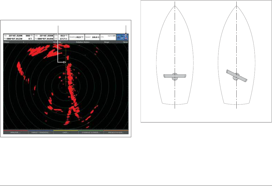
Check radar operation
Typical radar page
Points to check:
• Radar sweep with echo responses are shown on screen
• Radar status icon rotating in top right hand corner
If either of the above are not present this could indicate a fault.
Refer to the radar troubleshooting section for information.
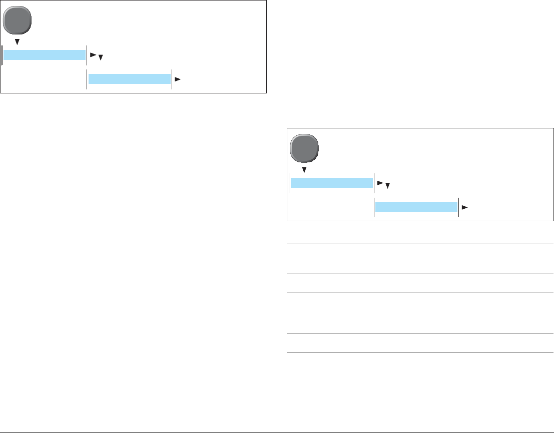
Check and adjust bearing alignment
Check and adjust the radar bearing alignment to ensure that radar
objects appear at the correct bearing relative to your boat’s bow.
You will need to check the radar bearing alignment for any scanner
installation that is not aligned with the boat.
Note: Bearing alignment should only be done after the compass
heading has been checked (page 82).
To check the bearing alignment
With your boat under way:
1. Align your boat’s bow with a stationary object identified on the
Radar display
An object between 1 & 2 NM distant is ideal.
D10342-1
Radar status
icon
Ship's Heading Marker
(SHM)
Radar scanner aligned
(bearing alignment should not be required)
Radar scanner NOT aligned
(bearing alignment will be required)
D10514-1
85 Chapter 8: Commissioning
2. Note the position of the object on the radar display. If the target
is not under the Ships heading marker (SHM), there is an align-
ment error and you will need to carry out bearing alignment
adjustment.
To adjust the bearing alignment
With a radar window active select the bearing alignment menu:
From the menu:
1. Press the BEARING ALIGNMENT softkey.
2. Use the rotary control to place the selected target under the
SHM.
3. Press OK when complete.
Parking settings (open array scanners)
To ensure the scanner parks (rests) in the correct position when
rotation stops, you may need to adjust the radar offset angle.
To adjust radar parking settings
From the Radar setup menu (radar in standby mode):
1. Select the PARKING OFFSET option, then adjust the offset
angle required to park the radar so that the antenna comes to
rest facing forward (you should see the Raymarine logo wording
from the front of the boat) when you place it in either standby or
switch it off.
2. Press OK when complete.
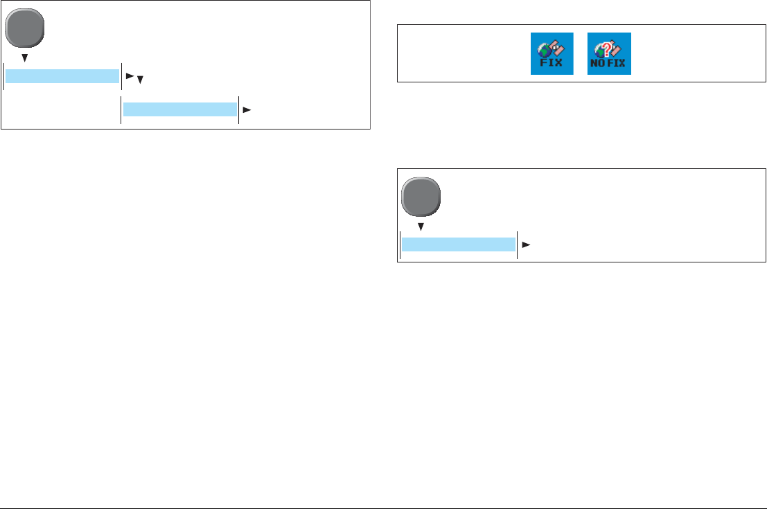
8.4 GPS checks
The GPS is required to show your boat position on the chart. You
can set up your GPS and check its status using the GPS status
icons and the GPS Status page of the Setup menu.
Check the GPS Status icon
This is located in the top right hand corner of the screen.
If NO FIX is displayed refer to the GPS status page (below) and
Troubleshooting section on page 95.
GPS Status page
D10343-1
MENU
RADAR SETUP
BEARING ALIGNMENT
D10346-1
D10344-1
MENU
GPS STATUS
G-Series Installation & Commissioning 86
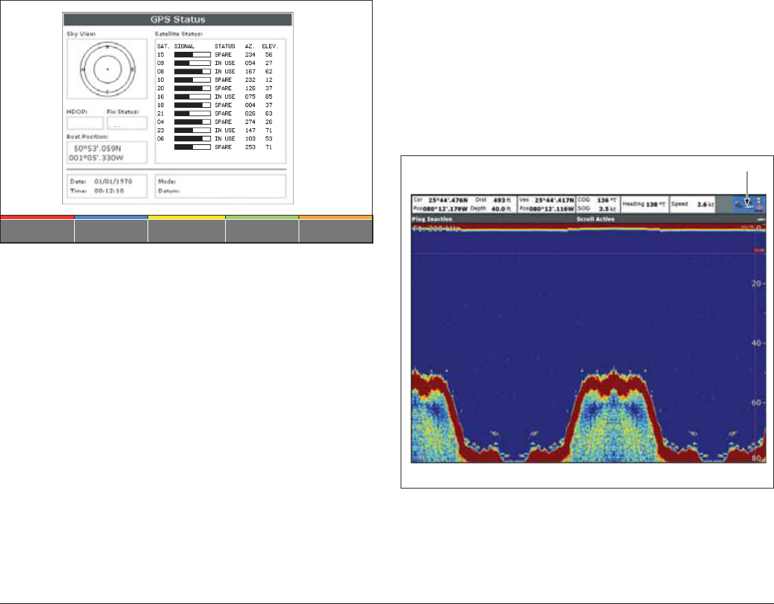
Typical GPS status screen
This screen may help diagnose a NO FIX status. It provides infor-
mation for each for each tracked GPS satellite.
HDOP
The HDOP (Horizontal Dilution Of Position) value shown on screen
provides an indication of the positional accuracy. This will vary
depending upon the relative position of the GPS satellites and the
prevailing conditions.
An ideal figure is 1.0. which indicates optimum accuracy.
A consistently high value (6 or above) may be associated with
NO-FIX occurring frequently. Check that the GPS antennae has a
clear view of the entire sky and refer to the troubleshooting section
on page 95.
See also
For further information and details regarding differential GPS, refer
to the separate user reference manual.
8.5 Fishfinder checks
For the fishfinder window to function the system must be connected
to a digital sounder (e.g. DSM400).
To select a fishfinder screen:
• Press the PAGE key to select from the current page set.
• Press and hold the PAGE key to select from all available
screens.
Typical fishfinder screen
Points to check:
• Fishfinder screen is scrolling and showing graphical
information.
• FIshfinder status icon animated in top right hand corner.
OTHER SETUPDIFF SETUP RESTART GPS
DIFF GPS
ON OFF
D10345-1
0
0
0
0
0
0
0
0
0
0
0
0
FIX STATUS
HDOP
122
00001.0 SD-FIX
SATELLITE DIFFERENTIAL
WGS 1984
D10351-1
Fishfinder status
icon
87 Chapter 8: Commissioning
• Valid depth and frequency values on screen
If any of the above are not present this could indicate a fault. Refer
to Chapter 9: Troubleshooting. Page 91.
Fault indications:
No Data
This is displayed if the system cannot detect a compatible DSM
sounder with appropriate transducer.
Invalid custom configuration
Indicates an invalid manual override of switch settings at the trans-
ducer. Refer to your DSM and Transducer documentation for
further information.
8.6 Set up video
To ensure correct operation of the video and entertainment system
you should setup and test all video and audio channels.
Before proceeding ensure that the video sources are operating. For
audio you should ensure that the amplifier is turned on with the
appropriate input selected.
Check the video and audio output
You will need to:
• Set up and select a video page
• Set up the video inputs
To set up a video page
1. Open the system Setup menu.
2. Open the Select Page Set screen.
3. Highlight the page set you want to edit.
4. Press the EDIT PAGE SET softkey:
5. Follow the on-screen instructions and select the video page
type as appropriate.
6. Press OK.
To select a video page
• Press the PAGE key to select from the current page set.
OR
• Press and hold the PAGE key to select from all available page
sets.
The audio (associated with input 4) will be heard through the con-
nected amplifier or television.
To set up video inputs
This menu provides the following options:
•Setup video cycle
You may set up display cycles for multiple video sources.
•Setup softkey shortcuts
You can set up the softkeys used to view the video channels on
the monitor.
•Configure video system
Set up S-Video and other video options (S-Video is only avail-
able on input 4). See Configure the video system .
•Reset GVM
Reset all options associated with the GVM400 video server(s)
to the factory default settings.
D10352-1
MENU
VIDEO SETUP MENU
G-Series Installation & Commissioning 88
Configure the video system
Select the required video input, then adjust the following options as
required:
•Rename GVM400 video unit
By default, the GVM video modules are labelled by their serial
number, e.g. “GVM400-0471123”. You can change these la-
bels to make them more descriptive.
•Rename video
By default, the video sources are labelled ‘Comp1’ to ‘Comp3’
and ‘S-Video’. You can change these labels to make them more
descriptive, for example: ’engine room’, ‘stern’, or ‘bow’.
•Type (Input 4 only)
By default input 4 is set to S-Video. If you want to use input 4 for
composite video, change this setting accordingly.
•Orientation
Use this option to change the orientation of the video image.
For example to display a mirror-image of the video feed if you
have a rear-facing camera linked to a forward-facing display.
•Aspect ratio
The video application automatically detects the appropriate as-
pect ratio for each input source. If an image appears distorted
(squashed or stretched), you can override the automatic setting
to choose the appropriate aspect ratio manually.
An aspect ratio of 4:3 is standard format, while 16:9 is wide-
screen format.
See also
• Please refer to the Reference Manual for more details.
• If any channel does not display correctly check the video and
SeaTalkhs connections. Also refer to Chapter
9: Troubleshooting
8.7 NMEA 0183
If you have a Navtex or AIS receiver connected to a NMEA 0183
port, you will need to change the NMEA Port Setting.
Set up the NMEA port using a monitor physically connected to the
correct GPM400 processor. (Refer to the details on your Nav Sta-
tion schematic diagrams)
NMEA Port settings
AIS checks
1. Check the AIS Status icon
D10600-1
MENU
VIDEO SETUP MENU
CONFIGURE VIDEO SYSTEM
Setting NMEA
equipment Additional information
NMEA 4800 General Default setting
Navtex 4800
or
Navtex 9600
Navtex receiver Please refer to your Navtex
receiver manual for appro-
priate settings.
AIS 38400 AIS receiver
D10353-1
MENU
SYSTEM SETUP
SYSTEM INTEGRATION
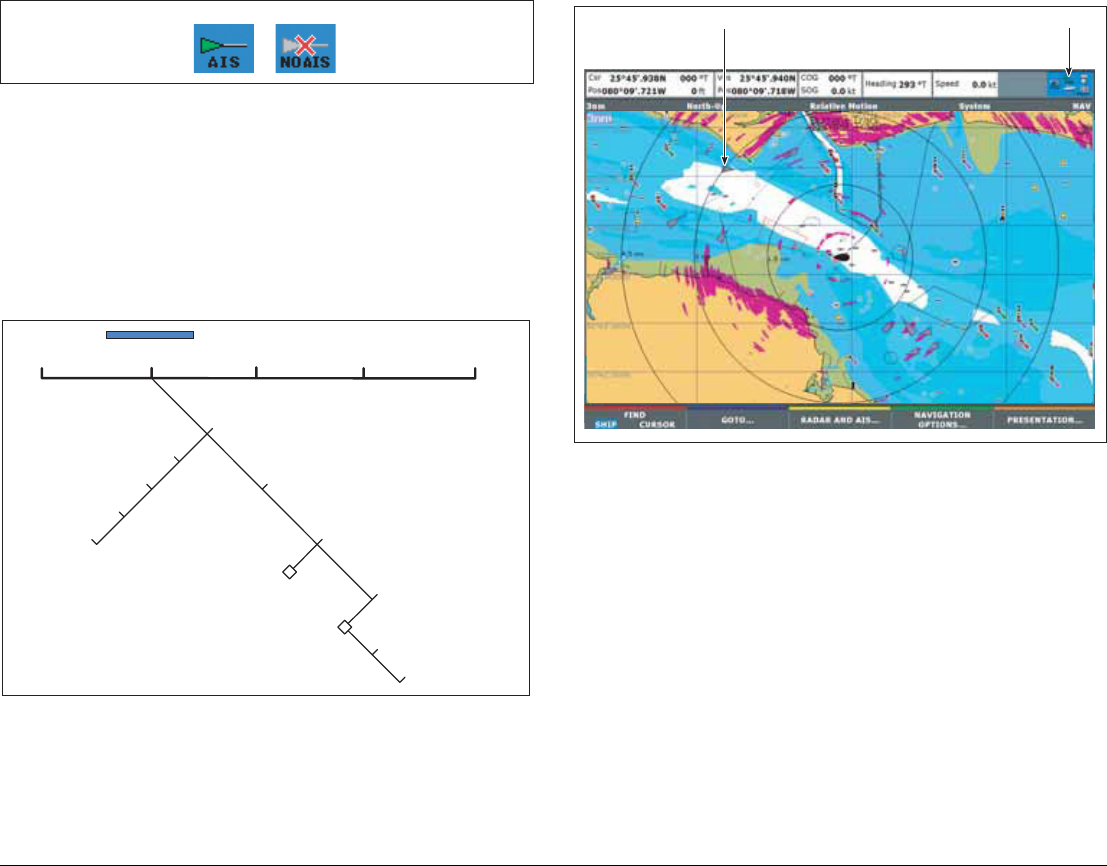
89 Chapter 8: Commissioning
This is located in the top right hand corner of the screen.
If NO AIS is displayed, please refer to the Troubleshooting section
on page 97.
2. Check that AIS targets are available
Use the chart window with radar overlay to check the AIS
operation.
Note: For dockside or dry-dock commission, you may not see
targets.
Use these softkey functions to view AIS targets
Typical AIS window
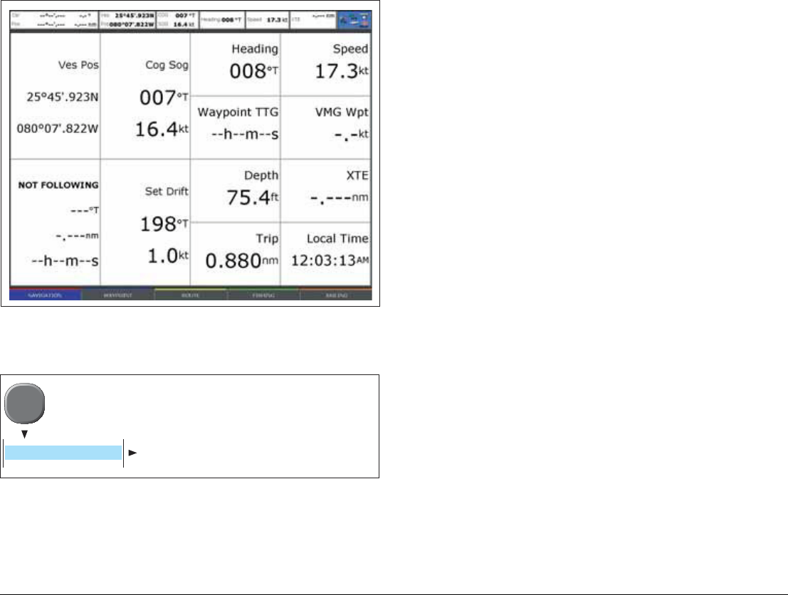
8.8 Data checks
Use the data window to check that the G-Series system is receiving
all necessary information from the marine electronics system. This
includes:
• Instrument and other data received via SeaTalkng.
• Engine data. Compatible engines may send information using
NMEA 2000. This can be then connected into the SeaTalkng
bus.
• Other data on the system (e.g. received via SeaTalk and
NMEA 0183).
To select the digital data page
• Press the PAGE key to select from the current page set.
D10356-1
VRM/EBL TARGET
TRACKING GAIN
Acquire target
Monitor in zones
MARPA & AIS options
Zone 1 on/off
Setup zone 1
Zone 2 on/off
Setup zone 2
Options window
MARPA list window
Cancel all targets
Cancel target
ENHANCE
ECHOES PRESENTATION
MARPA list
D10357-1
AIS status
icon
AIS target
G-Series Installation & Commissioning 90
• Press and hold the PAGE key to select from all available pages.
Typical instrument data window
To set up the digital data to be displayed
Open the Panel Setup Menu
Use this menu to add or remove types of data from the display.
Refer to the user reference manual for additional information.
D10354-1
D10334-1
MENU
PANEL SETUP MENU

9
Chapter 9: Troubleshooting
This section gives details for the troubleshooting the system. It covers common problems that may occur
during test and commissioning.
Chapter contents
• Power up on page 92
• Marine Monitors on page 92
• Keyboards on page 93
• Radar on page 94
• GPS on page 95
• Video on page 96
• Data on page 97
• Fishfinder on page 98
• SeaTalkhs Switch LED indications on page 98
• GPM400 LED indications on page 99
• GVM400 LED indications on page 100
• DSM400 LED indications on page 100

G-Series Installation & Commissioning 92
9.1 Troubleshooting
Power up
Marine Monitors
Problem Possible causes Possible solutions
• The system (or part of it) does not power up. • Power supply problem • Check relevant fuses and breakers.
• Check that the power supply cable is sound and that all
connections are tight and free from corrosion.
• Check that the power source is of the correct voltage and
sufficient current.
Problem Possible causes Possible solutions
• Monitor is blank. • The monitor is in standby mode. • Press the standby/power key on the monitor.
• The monitor has no power supply. • Refer to troubleshooting Power up on page 92.
• Monitor shows “Searching” or “No signal”
message.
• A repeat monitor during system start-up • Wait for a couple of minutes and see if the problem clears.
• The monitor is set to an incorrect input channel. • Press the channel select keys on the monitor to check all
input channels.
• A faulty connection to the GPM400 processor • Check the cable/connection between the monitor and the
GPM400 processor.
• The GPM400 processor is not operating
correctly.
• Check the GPM400 power supply.
Refer to troubleshooting Power up on page 92.
• Check the GPM400 status LEDs.
Refer to troubleshooting GVM400 LED indications on
page 100.
• Monitor picture is out of proportion • GPM has 2 monitors with different screen
resolutions
• GPM has 2 monitors with different aspect ratio
• Ensure that monitors connected to a single GPM have the
same screen resolution and aspect ratio.
• Monitor resolution is incorrect (display looks
pixelated or stretched/squashed)

93 Chapter 9: Troubleshooting
Keyboards
• The keyboard does not operate monitor setting
menus.
• On or more monitors are not listed when config-
uring the monitors or Nav Stations.
• SeaTalkhs network problem • Check the status of the SeaTalkhs Switch.
Refer to troubleshooting SeaTalkhs Switch LED indica-
tions on page 98
• Check the marine monitor and ensure that the network
selector switch is in the “up” position (required when
connected to the SeaTalkhs network).
• Check that the monitor and GPM400 are both connected
to the SeaTalkhs switch.
• Check that SeaTalkhs cables are free from damage.
• The monitor is not a Raymarine G-Series unit. • Only G-Series marine monitors are compatible with the
SeaTalkhs network required for this functionality.
• Software mismatch between equipment may
prevent communication.
• Contact Raymarine technical support
Problem Possible causes Possible solutions
Problem Possible causes Possible solutions
• Keyboard LCD is blank.
• (Monitor may also show no keyboards
connected message)
• The Keyboard is not connected to SeaTalkng or
has no power.
• Check keyboard wiring and power to SeaTalkng bus.
• Wireless keyboard is not charged up. • Connect wireless keyboard to charge point.
Keyboard LCD shows low battery • Wireless keyboard battery requires charging
• Degraded / old keyboard battery requires
replacing
• Charge keyboard battery at appropriate charge point.
• Replace battery
• Keyboard LCD shows sw version message.
e.g 86/78 F64D V0.6A
• (Monitor may also show no keyboards
connected message)
• The Keyboard cannot communicate with a
GPM400 processor
• Ensure GPM400 processors are connected to the
SeaTalkng system.
• Wireless basestation is not operating or is
disconnected from SeaTalkng.
• Check power and connections to SeaTalkng wireless
basestation.
• Wireless basestation is out of range • Re-survey wireless coverage and move / add repeat
basestations if necessary.

G-Series Installation & Commissioning 94
Radar
• Keypresses result in improper or no action at
the display.
• Software mismatch between equipment may
prevent communication.
• Contact Raymarine technical support
• Keyboard does not control the expected monitor
or Nav Station.
• Keyboard is not assigned to the correct Nav
Station(s).
• Assign keyboard to Nav station (see Assign Keyboards
on page 78).
• Incorrect monitor is selected at Keyboard • Check the Keyboard LCD to see which monitor is
currently being used. Use the left/right arrow keys to
select between the available monitors.
• Keyboard does not operate monitor setting
menus.
• Refer to troubleshooting Marine Monitors on page 92
Problem Possible causes Possible solutions
Problem Possible causes Possible solutions
• No Data or No scanner message. • Radar scanner power supply • Check that the scanner power supply cable is sound and
that all connections are tight and free from corrosion.
• Check relevant fuses and breakers.
• Check power source is of the correct voltage and suffi-
cient current (using voltage booster if appropriate).
• SeaTalkhs network problem • Check that all radar scanners are correctly connected to
the SeaTalkhs switch.
• Check the status of the SeaTalkhs Switch.
Refer to troubleshooting Status LEDs on page 98.
• Check that SeaTalkhs cables are free from damage.
• Radar scanner fault • Refer to the radar scanner handbook.
• Software mismatch between equipment may
prevent communication.
• Contact Raymarine technical support

95 Chapter 9: Troubleshooting
GPS
• Radar will not initialize
(Voltage control module (VCM) stuck in “sleep
mode”)
• Intermittent or poor power connection. • Check power connection at VCM.
(Voltage at input = 12 V, Voltage at output = 40 V)
• Switch at scanner pedestal in OFF position. • Ensure scanner pedestal switch is in ON position.
• The bearing given on the radar window differs
from the actual bearing.
• The radar bearing alignment requires
correcting.
• Perform the bearing alignment procedures. (See Check
and adjust bearing alignment on page 84).
Problem Possible causes Possible solutions
Problem Possible causes Possible solutions
• “No Fix” GPS status icon is displayed. • GPS equipment fault • Ensure that the GPS is functioning correctly (refer to
manufacturers handbook).
• GPS connection fault • Ensure that GPS connections and cabling are correct.
• GPS antenna in poor position
• GPS installation problem
• Ensure GPS antenna has a clear view of the sky.
• Refer to manufacturers handbook for installation details.
• Geographic location or prevailing conditions
preventing satellite fix.
• Check periodically to see if a fix is obtained in better
conditions or another geographic location.

G-Series Installation & Commissioning 96
Video
Problem Possible cause / solution Possible solutions
Video picture is unavailable at some or all
Nav stations.
• Video signal is not reaching the GVM400 video
module.
• Check the video source equipment.
• Check the video connections to the GVM400 unit.
• GVM400 video module or power supply
problem.
• Check the GVM400 status.
See troubleshooting GVM400 LED indications on
page 100.
• Check the GVM400 power supply.
Refer to troubleshooting Power up on page 92.
• SeaTalkhs network problem • Check that all GVM400 and all GPM400s are connected
to the SeaTalkhs switch.
• Check the status of the SeaTalkhs Switch.
Refer to troubleshooting Status LEDs on page 98
• Check that SeaTalkhs cables are free from damage.
• Software mismatch between equipment may
prevent communication.
• Contact Raymarine technical support

97 Chapter 9: Troubleshooting
Data
Problem Possible cause / solution Possible solutions
• Instrument or other system data is unavailable
at all Nav Stations.
• Data not received at Master GPM. • Check the data bus (e.g. SeaTalkng) wiring and connec-
tion to the master GPM.
• Check the overall integrity of the data bus (e.g.
SeaTalkng) wiring.
• If available refer to the reference guide for the data bus.
(e.g. SeaTalkng reference manual)
• Data source (e.g ST70 instrument) is not
operating.
• Check the source of the missing data (e.g. ST70
instrument)
• Refer to the manufacturers handbook for the equipment in
question.
• Software mismatch between equipment may
prevent communication.
• Contact Raymarine technical support
• Instrument or other system data is missing from
some but not all Nav Stations.
• SeaTalkhs network problem • Check that all GPM400s are connected to the SeaTalkhs
switch.
• Check the status of the SeaTalkhs Switch.
Refer to troubleshooting Status LEDs on page 98.
• Check that SeaTalkhs cables are free from damage.
• Software mismatch between equipment may
prevent communication.
• Contact Raymarine technical support

G-Series Installation & Commissioning 98
Fishfinder
9.2 Status LEDs
SeaTalkhs Switch LED indications
• Problem • Possible cause / solution • Possible solutions
• No data source for the fishfinder. • DSM power supply fault. • Check the DMS power supply.
Refer to troubleshooting Power up on page 92.
• Other DSM fault. • Refer to the instructions supplied with the DSM unit.
• SeaTalkhs network problem. • Check that the DSM is correctly connected to the
SeaTalkhs switch.
• Check the status of the SeaTalkhs Switch.
Refer to troubleshooting Status LEDs on page 98.
• Check that SeaTalkhs cables are free from damage.
• Software mismatch between equipment may
prevent communication.
• Contact Raymarine technical support
• Invalid custom configuration message • Indicates an invalid manual override of switch
settings at the transducer
• Refer to your DSM and Transducer documentation for
further information
LED State (Connected channels only) Causes
• For all connected channels:
1 steady and 1 flashing green LED.
• No problem detected
(Steady LED indicates network connection
Flashing LED indicates network traffic)
• No LEDs are illuminated • No power to SeaTalkhs switch
• Some LEDs are not illuminated • Cable / connection faults on the channels with non-illuminated LEDs.
• Equipment connected to non-illuminated LEDs may be faulty.

99 Chapter 9: Troubleshooting
GPM400 LED indications
Color Operation Causes
Normal operation
Green Flashing 500 / 500 ms • Normal operation (Heartbeat)
Green Flashing 750 / 250ms • Standby mode
Warnings and Errors
Off Off < 2 minutes
Off for > 2 minutes
• Startup
• No power
•
Amber On steady • Power on
• Lamp test
Amber Flashing x 1 • No link between processors (network fault)
Amber Flashing x 2 • No network / cable unplugged
Amber Flashing x 3 • Over temperature warning
Amber/Green Alternating 750/250 ms • Bootloader awaiting to be upgraded or downloading code
Amber/Red Alternating 750/250 ms • DOBII Download. This condition remains until a valid application is available
from Flash
Red Flashing x 1 • Fan fault
Red Flashing x 3 • Over temperature error
Red Flashing x 4 • Flash write error
Red Flashing x 5 • No application programmed
Red Flashing x 8
(May be followed by Flashing amber)
• Hardware fault

G-Series Installation & Commissioning 100
GVM400 LED indications
DSM400 LED indications
Color Operation Causes
Normal operation
Green Flashing
(various rates, depending upon system data)
• Normal operation
Warnings and Errors
Amber On steady • Power on
• Lamp test
Amber Flashing x 1 • Acquisition failure
Amber Flashing x 2 • No network / cable unplugged
Amber Flashing x 3 • Other network error
Amber/Red Alternating 750/250 ms • Software upgrade. This condition remains until a valid application is available
from Flash
Red Flashing x 1 • Unit can no longer poll input status
Red Flashing x 4 • Flash write error
Red Flashing x 6 • Video stopped
Red Flashing x 7 • Video error
Red Flashing x 8
(May be followed by Flashing amber)
• Hardware read failure
Color Operation Causes
Normal operation
Green Flashing 500 / 500 ms • Normal operation (Heartbeat)
Green Flashing 750 / 250ms • Standby mode

101 Chapter 9: Troubleshooting
Warnings and Errors
Off Off < 2 minutes
Off for > 2minutes
• Startup
• No power
•
Amber On steady • Power on
• Lamp test
Amber Flashing x 1 • Input transducer
Amber Flashing x 2 • No network / cable unplugged
Amber Flashing x 3 • Over temperature warning
Amber Flashing x 8 • Watchdog restart
Amber/Red Alternating 750/250 ms • Software upgrade. This condition remains until a valid application is available
from Flash
Red Flashing x 1 • Voltage error
Red Flashing x 3 • Over temperature error
Red Flashing x 4 • Flash write error
Red Flashing x 5 • No application programmed
Red Flashing x 8
(May be followed by Flashing amber)
• Hardware read failure
Color Operation Causes

G-Series Installation & Commissioning 102

G-Series Installation & Commissioning 103
Appendix ATechnical specification
GPM400 Processor module
GPM400 Processor module
Nominal supply
voltage
12 V / 24 VDC
Operating voltage
range
10.7 V to 32 V DC
Fuse / Breakers 12 V supply:
10 A fuse protection at distribution panel
10 A thermal circuit breaker protection at distribution
panel
24 V supply:
4 A fuse protection at distribution panel
5 A thermal circuit breaker protection at distribution
panel
Typical Power
consumption
No external loads
3 A @ 12 V
1.5 A @ 24 V
With external loads
5 A @ 12 V
2.5 A @ 24 V
Environmental
conditions:
operating temperature: -15°C to 55°C (5°F to 131°F)
non-operating temperature: -25°C to 70°C (-13°F to
158°F)
relative humidity limit: 80%
water protection: drip resistant when mounted
vertically
Storage conditions for
packaged unit:
Temperature: -25°C to 55°C (-13°F to 158°F)
relative humidity: 75%
Dimensions: Width = 335 mm (13.19 in)
Height =230 mm (9.06 in)
Depth = 125 mm (4.92 in),
Weight 6.5 kg (14.33 lb)
Data connections NMEA 0183 (x2)
SeaTalk
SeaTalkng
SeaTalkhs
Compact flash
USB (software upgrade only)
Video DVI x 2
(Optional VGA adaptor available)
Audio Stereo line out (rated 1 V rms)
SeaTalk / alarm power
output
250 mA at 12 V
CE approvals -
conforms to:
89/336/EEC as amended by 92/31/EEC,
EN60945:2002
GPM400 Processor module

G-Series Installation & Commissioning 104
GVM400 Video module
GVM400 Video module
Nominal supply
voltage
12 V / 24 V DC
Operating voltage
range
10.7 V to 32 V DC
Fuse / Breakers 12 V supply:
2 A fuse protection at distribution panel
1.2 A thermal circuit breaker protection at distribution
panel
24 V supply:
1 A fuse protection at distribution panel
1 A thermal circuit breaker protection at distribution
panel
Typical Power
consumption
650 mA @ 12 V
330 mA @ 24 V
Environmental
conditions:
operating temperature: -15°C to 55°C (5°F to 131°F)
non-operating temperature: -25°C to 70°C (-13°F to
158°F)
relative humidity limit: 80%
water protection: drip resistant when mounted
vertically
Storage conditions for
packaged unit:
Temperature: -25°C to 55°C (-13°F to 158°F)
relative humidity: 75%
Dimensions: Width = 237 mm (9.33 in)
Height = 170 mm (6.69 in)
Depth = 56 mm (2.20 in)
Weight 0.8 kg (1.76 lb)
Data connections SeaTalkhs
Video inputs Inputs 1-3: Composite video
(PAL 626 Line, NTSC 525 Line)
Input 4: S-Video or Composite video
Audio inputs Stereo audio line in (rated 1 V rms)
(associated with Input 4 (S-Video or composite)
CE approvals -
conforms to:
89/336/EEC as amended by 92/31/EEC,
EN60945:2002
GVM400 Video module

105
G-Series Keyboard
G-Series Keyboard
Nominal supply
voltage
12 V DC (From SeaTalkngbus)
Operating voltage
range
9 V to 16 V DC
Power consumption
(standby)
1.5 W
Environmental
conditions:
operating temperature: -15°C to 55°C (5°F to 131°F)
non-operating temperature: -25°C to 70°C (-13°F to
158°F)
relative humidity limit: 95%
water protection: waterproof to CFR-46 standard
Storage conditions
when packed:
Temperature: -25°C to 55°C (-13°F to 158°F)
relative humidity: 75%
Dimensions: (width, height, depth)
297 mm (11.69 in), 98 mm (3.86 in), 46 mm (1.81 in)
Weight 0.65 kg (1.43 lb)
Data connections SeaTalkng
SeaTalkng RF (requires wireless upgrade kit and sepa-
rate basestation)
Approvals: CE:
• EN60945, EN300-440-2
FCC:
• CFR47 PART 15
Other
• IC-RSS-210
G-Series Installation & Commissioning 106
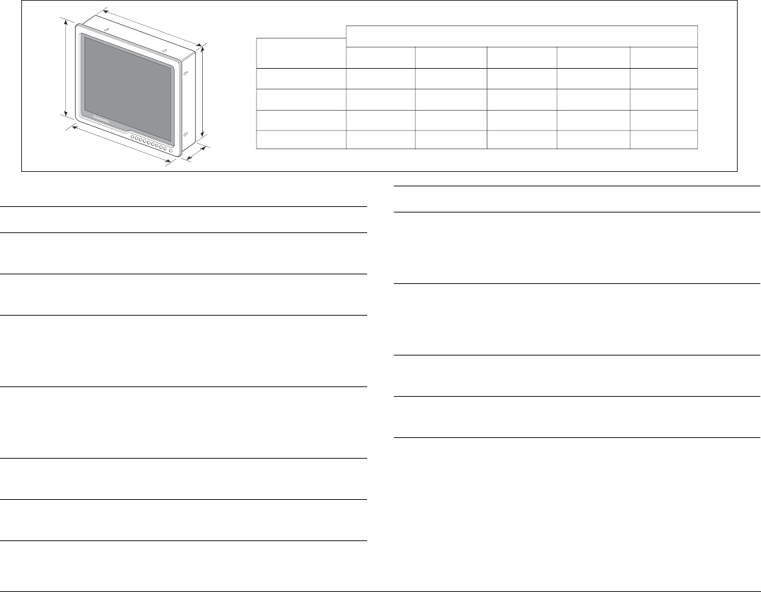
G-Series marine monitors
A
B
C
D
E
Display
G120 - 12 inch
G150 - 15 inch
G170 - 17 inch
G190 - 19 inch
A
330 (13.00)
380 (14.97)
415 (16.34)
454 (17.87)
B
284 (11.18)
315 (12.39)
358 (14.10)
389 (15.31)
C
307 (12.08)
357 (14.07)
394 (15.51)
432 (17.00)
D
257 (10.10)
292 (11.50)
335 (13.19)
366 (14.41)
E
118 (4.64)
118 (4.64)
100 (3.94)
100 (3.94)
Dimensions - mm (in)
G-Series marine monitors
Nominal supply
voltage
12 V / 24 V DC
Operating voltage
range
10.2 V to 32 V DC
Power consumption
(standby)
G170 - 7.6 amps at 12 V
3.5 amps at 24 V
G190 - 7.7 amps at 12 V
3.6 amps at 24 V
Environmental
conditions:
operating temperature: -10°C to 50°C (14°F to 122°F)
non-operating temperature: -20°C to 70°C (-4°F to
158°F)
water protection: waterproof to IP66 (from the front)
Storage conditions
when packed:
Temperature: -25°C to 55°C (-13°F to 158°F)
relative humidity: 75%
Dimensions: Refer to separate operators handbook for model
dimensions
Weight G120 - 4.6 kg (10 lbs)
G150 - 5.8 kg (12 lbs)
G170 - 6.4 Kg (14 lbs)
G190 - 7.3 Kg (16 lbs)
Video inputs 3 VGA
2 DVI-D
3 Composite video
1 S-Video
Data connections SeaTalkhs/Ethernet
Serial Port
Native resolution G120 / G150: 1024 x 768 (XGA)
G170 / G190: 1280 x 1024 (SXGA)
G-Series marine monitors

107
See also
• For additional specifications, refer to the documentation sup-
plied with the individual equipment.
Resolutions and
refresh rates
VGA - 60,72, 75 and 85 Hz
SVGA - 56, 60, 72, 75 and 85 Hz
XGA - 60, 70, 75 and 85 Hz
SXGA - 60, 75 and 85 Hz
UXGA - 60, 65, 70, 75 and 85 Hz
All timings in accordance with VESA Monitor Timing
Standards
Approvals: CE:
• 1999/5/EC, EN60945:2002
FCC:
• Part 80 (47CFR) and Part 2 (47CFR)
G-Series marine monitors

G-Series Installation & Commissioning 108
109
Appendix B - Nav Station schematic
Plan the connections and arrangement of your core system. This information is required when commissioning.
Nav station information Nav station name Nav station location
D10029-1
Display 1 Display 2 (if applicable)
Keyboard
GPM400 processor
9
WXYZ
8
TUV
7
PQRS
4
GHI
5
JKL
6
MNO
ACTIVE
WPTS
MOB
DATA
MENU
PAGE
.
0
2
ABC
3
DEF
1
CANCEL
STANDBY
DODGE PILOT OK
RANGE
OUT
IN
ENTER
SeaTalkng
Serial number
Location
Wireless (delete as appropriate)
YES / NO
Master GPM (delete as appropriate)
YES / NO
Master GPM (delete as appropriate)
YES / NO
SeaTalkhs (delete as appropriate)
SeaTalkhs switch
Name
Location
IP address (When on SeaTalkhs only)
Video connection (delete as appropriate)
DVI / VGA
YES / NO
SeaTalkhs (delete as appropriate)
Name
Location
IP address (When on SeaTalkhs only)
Video connection (delete as appropriate)
DVI / VGA
YES / NO
Serial Number
Location
Serial number
Location
GPM400 processor
Serial number
Location
Bridge - Right
BridgeBridge
10-2-0-14
-
-
-
-
-
10-2-0-2
Bridge - Left
1006021 1006024
Left (switch cupboard) Right (switch cupboard)
02070016
Bridge
-
-
Bridge nav Bridge
G-Series Installation & Commissioning 110
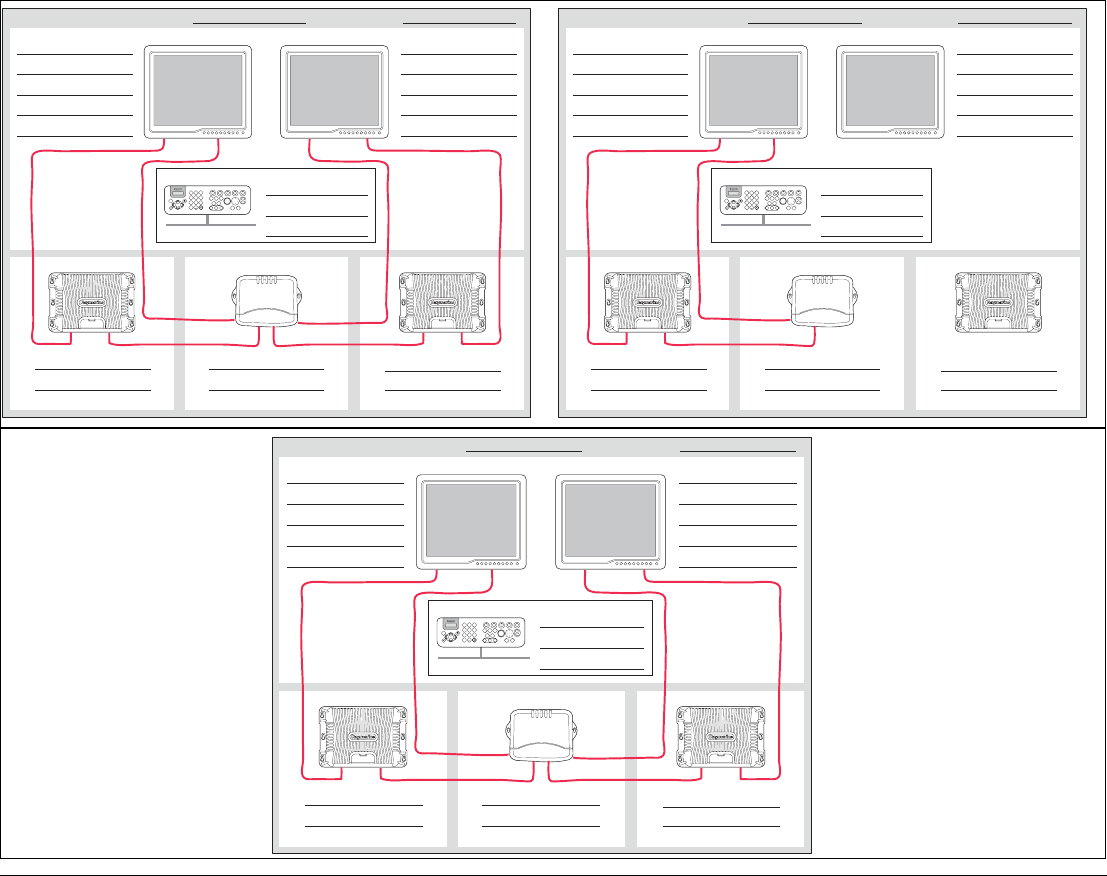
If required use multiple sheets, as shown in the example system below.
Nav station information Nav station name Nav station location
D10029-1
Display 1 Display 2 (if applicable)
Keyboard
GPM400 processor
9
WXYZ
8
TUV
7
PQRS
4
GHI
5
JKL
6
MNO
ACTIVE
WPTS
MOB
DATA
MENU
PAGE
.0
2
ABC
3
DEF
1
CANCEL
STANDBY
DODGE PILOT OK
RANGE
OUT
IN
ENTER
SeaTalkng
Serial number
Location
Wireless (delete as appropriate)
YES / NO
Master GPM (delete as appropriate)
YES / NO
Master GPM (delete as appropriate)
YES / NO
SeaTalkhs (delete as appropriate)
SeaTalkhs switch
Name
Location
IP address (When on SeaTalkhs only)
Video connection (delete as appropriate)
DVI / VGA
YES / NO
SeaTalkhs (delete as appropriate)
Name
Location
IP address (When on SeaTalkhs only)
Video connection (delete as appropriate)
DVI / VGA
YES / NO
Serial Number
Location
Serial number
Location
GPM400 processor
Serial number
Location
Bridge - Right
BridgeBridge
10-2-0-14
-
-
-
-
-
10-2-0-2
Bridge - Left
1006021 1006024
Left (switch cupboard) Right (switch cupboard)
02070016
Bridge
-
-
Bridge nav Bridge Nav station information Nav station name Nav station location
D10029-1
Display 1 Display 2 (if applicable)
Keyboard
GPM400 processor
9
WXYZ
8
TUV
7
PQRS
4
GHI
5
JKL
6
MNO
ACTIVE
WPTS
MOB
DATA
MENU
PAGE
.0
2
ABC
3
DEF
1
CANCEL
STANDBY
DODGE PILOT OK
RANGE
OUT
IN
ENTER
SeaTalkng
Serial number
Location
Wireless (delete as appropriate)
YES / NO
Master GPM (delete as appropriate)
YES / NO
Master GPM (delete as appropriate)
YES / NO
SeaTalkhs (delete as appropriate)
SeaTalkhs switch
Name
Location
IP address (When on SeaTalkhs only)
Video connection (delete as appropriate)
DVI / VGA
YES / NO
SeaTalkhs (delete as appropriate)
Name
Location
IP address (When on SeaTalkhs only)
Video connection (delete as appropriate)
DVI / VGA
YES / NO
Serial Number
Location
Serial number
Location
GPM400 processor
Serial number
Location
Bridge
3
10-2-0-20
-
-
-
-
Bridge - Radar 1
1006026
Middle (Switch cupboard)
02070016
Bridge
-
Bridge nav Bridge
Nav station information Nav station name Nav station location
D10029-1
Display 1 Display 2 (if applicable)
Keyboard
GPM400 processor
9
WXYZ
8
TUV
7
PQRS
4
GHI
5
JKL
6
MNO
ACTIVE
WPTS
MOB
DATA
MENU
PAGE
.0
2
ABC
3
DEF
1
CANCEL
STANDBY
DODGE PILOT OK
RANGE
OUT
IN
ENTER
SeaTalkng
Serial number
Location
Wireless (delete as appropriate)
YES / NO
Master GPM (delete as appropriate)
YES / NO
Master GPM (delete as appropriate)
YES / NO
SeaTalkhs (delete as appropriate)
SeaTalkhs switch
Name
Location
IP address (When on SeaTalkhs only)
Video connection (delete as appropriate)
DVI / VGA
YES / NO
SeaTalkhs (delete as appropriate)
Name
Location
IP address (When on SeaTalkhs only)
Video connection (delete as appropriate)
DVI / VGA
YES / NO
Serial Number
Location
Serial number
Location
GPM400 processor
Serial number
Location
FlyBridge - Right
BridgeBridge
10-2-0-36
-
-
-
-
-
10-2-0-37
FlyBridge - Left
Repeat Repeat
1006021 1006024
Left (switch cupboard) Right (switch cupboard)
03070030
Bridge
-
-
FlyBridge Fly Bridge
Example notes:
Bridge (Above)
• 3 displays all controlled by a single
keyboard.
Flybridge (Right)
• 2 repeat displays with a single
keyboard.
In this example system, the flybridge
does not repeat the dedicated radar
display used on the bridge.

111
Nav station information Nav station name Nav station location
D10029-1
Display 1 Display 2 (if applicable)
Keyboard
GPM400 processor
9
WXYZ
8
TUV
7
PQRS
4
GHI
5
JKL
6
MNO
ACTIVE
WPTS
MOB
DATA
MENU
PAGE
.0
2
ABC
3
DEF
1
CANCEL
STANDBY
DODGE PILOT OK
RANGE
OUT
IN
ENTER
SeaTalkng
Serial number
Location
Wireless (delete as appropriate)
YES / NO
Master GPM (delete as appropriate)
YES / NO
Master GPM (delete as appropriate)
YES / NO
SeaTalkhs (delete as appropriate)
SeaTalkhs switch
Name
Location
IP address (When on SeaTalkhs only)
Video connection (delete as appropriate)
DVI / VGA
YES / NO
SeaTalkhs (delete as appropriate)
Name
Location
IP address (When on SeaTalkhs only)
Video connection (delete as appropriate)
DVI / VGA
YES / NO
Serial Number
Location
Serial number
Location
GPM400 processor
Serial number
Location

G-Series Installation & Commissioning 112
Nav station information Nav station name Nav station location
D10029-1
Display 1 Display 2 (if applicable)
Keyboard
GPM400 processor
9
WXYZ
8
TUV
7
PQRS
4
GHI
5
JKL
6
MNO
ACTIVE
WPTS
MOB
DATA
MENU
PAGE
.0
2
ABC
3
DEF
1
CANCEL
STANDBY
DODGE PILOT OK
RANGE
OUT
IN
ENTER
SeaTalkng
Serial number
Location
Wireless (delete as appropriate)
YES / NO
Master GPM (delete as appropriate)
YES / NO
Master GPM (delete as appropriate)
YES / NO
SeaTalkhs (delete as appropriate)
SeaTalkhs switch
Name
Location
IP address (When on SeaTalkhs only)
Video connection (delete as appropriate)
DVI / VGA
YES / NO
SeaTalkhs (delete as appropriate)
Name
Location
IP address (When on SeaTalkhs only)
Video connection (delete as appropriate)
DVI / VGA
YES / NO
Serial Number
Location
Serial number
Location
GPM400 processor
Serial number
Location
113
Nav station information Nav station name Nav station location
D10029-1
Display 1 Display 2 (if applicable)
Keyboard
GPM400 processor
9
WXYZ
8
TUV
7
PQRS
4
GHI
5
JKL
6
MNO
ACTIVE
WPTS
MOB
DATA
MENU
PAGE
.0
2
ABC
3
DEF
1
CANCEL
STANDBY
DODGE PILOT OK
RANGE
OUT
IN
ENTER
SeaTalkng
Serial number
Location
Wireless (delete as appropriate)
YES / NO
Master GPM (delete as appropriate)
YES / NO
Master GPM (delete as appropriate)
YES / NO
SeaTalkhs (delete as appropriate)
SeaTalkhs switch
Name
Location
IP address (When on SeaTalkhs only)
Video connection (delete as appropriate)
DVI / VGA
YES / NO
SeaTalkhs (delete as appropriate)
Name
Location
IP address (When on SeaTalkhs only)
Video connection (delete as appropriate)
DVI / VGA
YES / NO
Serial Number
Location
Serial number
Location
GPM400 processor
Serial number
Location

G-Series Installation & Commissioning 114
Nav station information Nav station name Nav station location
D10029-1
Display 1 Display 2 (if applicable)
Keyboard
GPM400 processor
9
WXYZ
8
TUV
7
PQRS
4
GHI
5
JKL
6
MNO
ACTIVE
WPTS
MOB
DATA
MENU
PAGE
.0
2
ABC
3
DEF
1
CANCEL
STANDBY
DODGE PILOT OK
RANGE
OUT
IN
ENTER
SeaTalkng
Serial number
Location
Wireless (delete as appropriate)
YES / NO
Master GPM (delete as appropriate)
YES / NO
Master GPM (delete as appropriate)
YES / NO
SeaTalkhs (delete as appropriate)
SeaTalkhs switch
Name
Location
IP address (When on SeaTalkhs only)
Video connection (delete as appropriate)
DVI / VGA
YES / NO
SeaTalkhs (delete as appropriate)
Name
Location
IP address (When on SeaTalkhs only)
Video connection (delete as appropriate)
DVI / VGA
YES / NO
Serial Number
Location
Serial number
Location
GPM400 processor
Serial number
Location
115
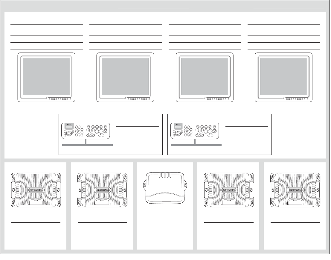
Nav station information Nav station name Nav station location
D10575-1
Display 1
Keyboard
GPM400 processor
9
WXYZ
8
TUV
7
PQRS
4
GHI
5
JKL
6
MNO
ACTIVE
WPTS
MOB
DATA
MENU
PAGE
.0
2
ABC
3
DEF
1
CANCEL
STANDBY
DODGE PILOT OK
RANGE
OUT
IN
ENTER
SeaTalkng
Master GPM (delete as appropriate)
YES / NO
DVI / VGA
YES / NO
SeaTalkhs (delete as appropriate)
IP address (when on SeaTalkhs only)
Video (delete as appropriate)
Serial Number
Location
GPM400 processor
Master GPM (delete as appropriate)
YES / NO
Serial Number
Location
Wireless (delete as appropriate)
YES / NO
Serial Number
Location
Name Location
Keyboard
9
WXYZ
8
TUV
7
PQRS
4
GHI
5
JKL
6
MNO
ACTIVE
WPTS
MOB
DATA
MENU
PAGE
.0
2
ABC
3
DEF
1
CANCEL
STANDBY
DODGE PILOT OK
RANGE
OUT
IN
ENTER
SeaTalkng
Wireless (delete as appropriate)
YES / NO
Serial Number
Location
GPM400 processor
Master GPM (delete as appropriate)
YES / NO
Serial Number
Location
GPM400 processor
Master GPM (delete as appropriate)
YES / NO
Serial Number
Location
SeaTalkhs switch
Location
Serial Number
Display 2
DVI / VGA
YES / NO
SeaTalkhs (delete as appropriate)
IP address (when on SeaTalkhs only)
Video (delete as appropriate)
Name Location
Display 3
DVI / VGA
YES / NO
SeaTalkhs (delete as appropriate)
IP address (when on SeaTalkhs only)
Video (delete as appropriate)
Name Location
Display 4
DVI / VGA
YES / NO
SeaTalkhs (delete as appropriate)
IP address (when on SeaTalkhs only)
Video (delete as appropriate)
Name Location
G-Series Installation & Commissioning 116
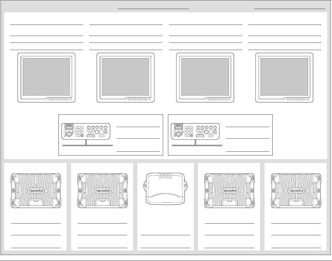
Nav station information Nav station name Nav station location
D10575-1
Display 1
Keyboard
GPM400 processor
9
WXYZ
8
TUV
7
PQRS
4
GHI
5
JKL
6
MNO
ACTIVE
WPTS
MOB
DATA
MENU
PAGE
.0
2
ABC
3
DEF
1
CANCEL
STANDBY
DODGE PILOT OK
RANGE
OUT
IN
ENTER
SeaTalkng
Master GPM (delete as appropriate)
YES / NO
DVI / VGA
YES / NO
SeaTalkhs (delete as appropriate)
IP address (when on SeaTalkhs only)
Video (delete as appropriate)
Serial Number
Location
GPM400 processor
Master GPM (delete as appropriate)
YES / NO
Serial Number
Location
Wireless (delete as appropriate)
YES / NO
Serial Number
Location
Name Location
Keyboard
9
WXYZ
8
TUV
7
PQRS
4
GHI
5
JKL
6
MNO
ACTIVE
WPTS
MOB
DATA
MENU
PAGE
.0
2
ABC
3
DEF
1
CANCEL
STANDBY
DODGE PILOT OK
RANGE
OUT
IN
ENTER
SeaTalkng
Wireless (delete as appropriate)
YES / NO
Serial Number
Location
GPM400 processor
Master GPM (delete as appropriate)
YES / NO
Serial Number
Location
GPM400 processor
Master GPM (delete as appropriate)
YES / NO
Serial Number
Location
SeaTalkhs switch
Location
Serial Number
Display 2
DVI / VGA
YES / NO
SeaTalkhs (delete as appropriate)
IP address (when on SeaTalkhs only)
Video (delete as appropriate)
Name Location
Display 3
DVI / VGA
YES / NO
SeaTalkhs (delete as appropriate)
IP address (when on SeaTalkhs only)
Video (delete as appropriate)
Name Location
Display 4
DVI / VGA
YES / NO
SeaTalkhs (delete as appropriate)
IP address (when on SeaTalkhs only)
Video (delete as appropriate)
Name Location

117
Appendix C - Spares and accessories
Note: Parts marked with an asterisk * are supplied as standard
with certain G-Series equipment. See Chapter 3: Packs and
contents. Page 23 for details.
Cables
The following cables are available as accessories:
Description Part No.
Marine monitor cables
5 m (16.4 ft) DVI to DVI (digital) cable E06021
10 m (32.8 ft) DVI to DVI (digital) cable E06022
500 mm (19.69 in) DVI to VGA (analogue) cable E06053
1.5 m (4.9 ft) VGA to VGA cable R08130
5 m (16.4 ft) VGA to VGA cable*R08174*
10 m (32.8 ft) VGA to VGA cable R08296
20 m VGA to VGA cable R08297
SeaTalk
1.5 m (4.9 ft) SeaTalk/Alarm Out cable*E55054*
SeaTalkhs cables
1.5 m (4.9 ft) SeaTalkhs network cable E55049
5 m (16.4 ft) SeaTalkhs network cable E55050
10 m (32.8 ft) SeaTalkhs network cable E55051
15 m (49.2 ft) SeaTalkhs network cable A62135
20 m (65.6 ft) SeaTalkhs network cable E55052
1.5 m (4.9 ft) SeaTalkhs patch cable E06054
5 m (16.4 ft) SeaTalkhs patch cable E06055
10 m (32.8 ft) SeaTalkhs patch cable E06056
15 m (49.2 ft) SeaTalkhs patch cable A62136
20 m (65.6 ft) SeaTalkhs patch cable E06057
SeaTalkng cables / connectors
400 mm (15.75 in) SeaTalkng backbone cable A06033
400 mm (15.75 in) SeaTalkng spur cable A06038
1 m (3.3 ft) SeaTalkng spur cable*A06039*
3 m (9.8 ft) SeaTalkng spur cable A06040
5 m (16.4 ft) SeaTalkng spur cable A06041
1 m (3.3 ft) SeaTalkng spur cable (bare ends) A06043
3 m (9.8 ft) SeaTalkng spur cable (bare ends) A06044
SeaTalkng T-Piece connector*A06028*
NMEA 2000 cables
1.5 m (4.9 ft) SeaTalkng to DeviceNet male A06046
NMEA 0183 cables
1.5 m (4.9 ft) NMEA 0183 cable*R08004*
Power cables
1.5 m (4.9 ft) Power cable*R08003*
Description Part No.

G-Series Installation & Commissioning 118
Spare parts
Audio/Entertainment
1.5 m (4.9 ft) GVM400 Audio cable*R08275*
1.5 m (4.9 ft) GVM400 S-Video cable*R08274*
3 m (9.8 ft) G-Series Audio out cable*R08266*
15 m (49.2 ft) G-Series Audio out cable R08298
Service and Maintenance
This product contains no user serviceable
components. Please refer all maintenance and
repair to authorized Raymarine dealers.
Unauthorized repair may affect your warranty.
GPM400 processor module spares
Description Part No.
US Cartography Hard Drive R08267
EU Cartography Hard Drive R08268
ROW Cartography Hard Drive R08269
Hard Drive Cable R08270
COM Express CPU Module Assembly R08271
GPM400 Baseboard R08272
GPM400 Connector Panel Assembly R08273
Chart Door (encl. seal) R08002
Description Part No. GPM400 internal Fan Assembly R08299
GPM400 Main Fan Assembly R08300
SeaTalk NG Locking Collar (white) A06051
GPM400 Install Pack R08295
Keyboard spares
Description Part No.
Keyboard
Sun cover R08307
Rear cover / mounting bracket R08308
Screw pack R08309
Wireless upgrade kit
Keyboard Charge Cable 2.5m R08310
STNG Bulkhead Mounting Cable R08311
Battery pack R08312
Allen Head M3 Screws (4x) R08313
Mounting Plate R08314
Connector Cover R08315
Mounting Screws (self tapping) 3x R08316
Dust Cap R08317
Allen key R08338

119
GVM400 video module spares
Description Part No.
GVM Connector Cover R08276
GVM install pack R08318
SeaTalkhs Switch module spares
Description Part No.
SeaTalkhs Swtich E55058

G-Series Installation & Commissioning 120

121
Index
Numerics
3rd party monitors 39
A
Accessories 117
AIS
checks 88
connection 53
Alarm
cables 51
connection 50
Alarm buzzer 29, 67
installation 67
Alarm output 50
Audio
cables 46
Audio output connection 46
Autopilot
SeaTalk connection 50
AWG 36
B
Bearing alignment 84
Breaker
rating 35
sharing 34
Breakers
turn on 70, 74
C
Cable
audio 46
charging 43
digital radar 49
gauge 36
general instructions 32
keyboard 42
NMEA 0183 52
power 35
routing 32
SeaTalk / alarm 51
SeaTalkhs 47
shielding 32
strain relief 32
types and length 32
Cable entry 58
Cables 31
spares 117
video/entertainment 46
Cables and connections 31
Cautions 7
Charging
cable 43
keyboard 64
Check system 70
Chinese 82
Circuit
isolation 32
protection 35
Cleaning 7
Clearances
GPM400 60
Command Center Keyboard - see Keyboard
Commissioning 81
introduction 13
Compass
swing 82
Compass heading 82
Configuration 74
Connection
digital radar 49
DSM 48

G-Series Installation & Commissioning 122
keyboard 40
monitor 38
NMEA 2000 55
SeaTalkng 54
Connections 31, 37
Contents
pack 23
Current Master 76
D
Danish 82
Dashboard
cable 43
Data
digital data 89
troubleshooting 97
Digital radar
cables 49
connection 49
Digital sounder
connection 48
Disclaimer 9
Displays - See monitors
DSM400
connection 48
LED indications 100
Dutch 82
DVI 39, 46
E
EMC installation guidelines 7, 32
English (UK) 82
English (US) 82
Entertainment
cables 46
connections 43
Entertainment system 21
Environment
GPM400 60
keyboard 61
keyboard - wireless upgrade 62
F
Fastheading
connection 52
ferrites 8
Finnish 82
Fishfinder
checks 86
troubleshooting 98
French 82
Fuse 35
in-line 34
G
Gauge
cable 36
German 82
GPM400
checks 70
connections 37
installation 59
LED indications 99
master 37
pack items 24
power cable 36
Spares 118
specification 103
GPM400 processor 37
GPS
checks 85
connection 49
SeaTalk connection 50
status icon 85
troubleshooting 95
Greek 82
Grounding 34
GVM400

123
checks 70
installation 66
LED indications 100
Pack items 25
power cable 36
spares 119
specification 104
GVM400 Video Module 66
H
Handbook information 12
HDOP 86
High voltage
warning 7
I
Icelandic 82
Ignition hazards 58
Initial Setup 73
Initialize radar 83
In-line fuse 34
Install
introduction 12
Installation
warning 7
Installation and mounting 57
Instruments
SeaTalk connection 50
IP Address
monitor 39
Isolation 32
Italian 82
J
Japanese 82
K
Keyboard
assign 78
cables 42
checks 70
connections 40
dimensions 61
installation 60
pack items 26
spares 118
specification 105, 106
troubleshooting 93
wired 40, 41
wireless 41
wireless upgrade kit 27
Keyboard Configuration 78
Korean 82
L
Language setting 82
LEDs 98
Linearize the compass 82
Loads
circuit 35
Local GPM 76
Location
equipment 58
Loops
ground 34
M
Master GPM 37, 50
select 75
Monitor
3rd party 39
cables 39
checks 70
connections 38

G-Series Installation & Commissioning 124
power cable 36
repeat 38
Monitor connections 38
Monitors
assign to a nav station 77
installation 65
pack items 28
troubleshooting 92
Mounting 57
alarm buzzer 67
GPM400 60
GVM400 66
keyboard 61
surface 58
N
Nav Station 74
configure 77
typical arrangement 75
Navtex 88
Network
SeaTalkhs 47
Network system 19
NMEA 0183
cables 52
connections 51
GPS 49
set up 88
NMEA 2000 connections 55
Norwegian 82
P
Packs and contents 23
Parking
radar 85
Patch
cable 48
Plan your installation 12
Portuguese 82
Positive ground 7, 34
Power
cables 35
distribution 33
Power supply
SeaTalk / alarm output 50
Power up
test 70
Powering up 74
precautions 69, 74
sequence 70
Power-up
troubleshooting 92
R
Radar
cables 49
checks 84
connection 49
initialize 83
setup 83
troubleshooting 94
warning 7
Repeat monitors 38
Routing cables 32
Russian 82
S
Schematic diagram 12, 32, 73
example 109
SeaTalk
cables 51, 55
connection 50
GPS 49
SeaTalkhs
cables 47
compatible devices 47
connections 47
devices 47

125
LED indications 98
Switch 47
switch checks 70
video connection 43
SeaTalkhs network 47
SeaTalkhs Network cables 47
SeaTalkng
connections 54
keyboard connection 42
typical system 54
Wireless basestation 28
Select Master GPM 76
Setup
initial 73
Shielding 32
Site survey 65
Spanish 82
Spares 117
Specification 103
monitors 106
Status icon
GPS 85
Status LEDs 98
Status page
GPS 85
Strain relief 32
Sun covers 7
Suppression ferrites 8
S-Video
cable 46
Swedish 82
System
checks 70
System overview 16
T
Technical specification 103
Thermal breaker 35
Transmit
radar 83
Troubleshooting 91, 92
Typical systems 15
V
Ventilation 58
VGA 39, 46
Video
cables 46
connections 43
set up 87
troubleshooting 96
Video output connection 46
W
Warnings and cautions 5, 7
Warranty 8
WEEE 8
Wired keyboard 40
Wireless
keyboard 41
Wireless basestation 43, 64
installation 64
pack items 28
Wireless coverage 65
Wireless upgrade
installation 62
Wireless upgrade kit 62
pack items 27

G-Series Installation & Commissioning 126

Raymarine plc
Anchorage Park, Portsmouth,
Hampshire, PO3 5TD, UK
Tel: +44 (0) 23 9269 3611
Fax: +44 (0) 23 9269 4642
www.raymarine.com
Raymarine Inc.
21 Manchester Street, Merrimack,
New Hampshire 03054 USA,
Tel: +1 603 881 5200
Fax: +1 603 864 4756
www.raymarine.com