Flir BelgiumBA STNGB Low-power (unlicensed) wireless device for leisure User Manual 87086 1
Raymarine UK Ltd. Low-power (unlicensed) wireless device for leisure 87086 1
Contents
Gseries Base Station
1
G-Series control keyboard
Wireless base station
Installation instructions
Waste Electrical and Electronic Equipment Directive
The Waste Electrical and Electronic Equipment (WEEE) Directive requires
the recycling of waste electrical and electronic equipment. Whilst the WEEE
Directive does not apply to some of Raymarine’s products, we support its
policy and ask you to be aware of how to dispose of this product.
The crossed out wheeled bin symbol, illustrated above, and found on our
products signifies that this product should not be disposed of in general
waste or landfill.
Please contact your local dealer, national distributor or Raymarine Technical
Services for information on product disposal.
Disclaimer
The technical and graphical information contained in this document, to the best of our
knowledge, was correct as it went to press. However, our policy of continuous improve-
ment and updating may change product specifications without prior notice. As a result,
unavoidable differences between the product and handbook may occur from time to
time. Raymarine cannot accept responsibility for any inaccuracies or omissions it may
contain. For the latest product information visit our website - www.raymarine.com
EMC installation guidelines
Raymarine equipment and accessories conform to the appropriate Electromagnetic
Compatibility (EMC) regulations. This minimizes electromagnetic interference between
equipment, which could otherwise affect the performance of your system.
Correct installation is required to ensure that EMC performance is not compromised.
FCC and Industry Canada Information
The G-Series control keyboard and wireless base station comply with US CFR47 part
15 Rules and with IC Standard RSS210. Operation is subject to the following two condi-
tions: (1) these devices may not cause harmful interference and (2) these devices must
accept interference received, including interference that may cause undesired
operation.
Changes or modifications to these devices not expressly approved in writing by Rayma-
rine could violate compliance with FCC or IC rules, and void the user's authority to
operate the equipment.
Declaration of Conformity
Raymarine UK Ltd. hereby declares that the G-Series Control Keyboard and Wireless
base station are in compliance with the essential requirements and other relevant provi-
sions of the R&TTE Directive 1999/5/EC.
The original Declarations of Conformity may be viewed on the relevant product pages at
www.raymarine.com.
Product installation
This equipment must be installed and operated in
accordance with the Raymarine instructions
provided. Failure to do so could result in poor
product performance, personal injury, and/or
damage to your boat.
Service and maintenance
This product contains no user serviceable
components. Please refer all maintenance and
repair to authorized Raymarine dealers.
Unauthorized repair may affect your warranty.
Cleaning
DO NOT use acid, ammonia based or abrasive
products.
DO NOT use commercial high pressure washing
(jet wash) equipment.
Document number: 87086-1
Date: October 2007
87086_1.book Page 1 Thursday, October 4, 2007 8:47 AM
2
Handbook information
This installation guide contains information required to successfully
install and set up your wireless base station.
It is part of a series of documents associated with the G-Series
system. All documents can be downloaded from:
www.raymarine.com/handbooks.
G-Series system documentation
Additional documents
You may also refer to separate instructions provided with the asso-
ciated ancillary equipment.
Errata
The documents supplied with the G-Series system contain a small
number of known errors:
87070-1 G-Series system installation guide
Page 20. System shown has one keyboard base station serving 2
keyboards, where 2 base stations are actually required. Each
keyboard requires a dedicated base station.
Page 41 & 42. Connection shows keyboard connected via ST70
instrument. Keyboards must be connected to a dedicated T-piece.
Page 65. Repeat base stations. These are not available for the wire-
less keyboard.
Installation sequence
Installation of the wireless keyboard system requires a structured
and planned approach. Use the following sequence of tasks:
Title Part number
G-Series system installation & commissioning
instructions
87070
G-Series command center keyboard installation
instructions
87084
G-Series command center keyboard wireless upgrade
kit installation instructions
87085
G- Series system operating guide 86126
G-Series system user reference guide 81276
PLANNING
1Check pack contents
2Plan system layout
3Charge keyboard
4Site Survey
We strongly recommend that you produce a complete schematic diagram for
your G-Series installation. Refer to the G-Series system installation and commis-
sioning instructions for templates and further information.
MOUNTING & CONNECTION
5Mount base station in selected location.
6Make all connections into equipment.
87086_1.book Page 2 Thursday, October 4, 2007 8:47 AM
3
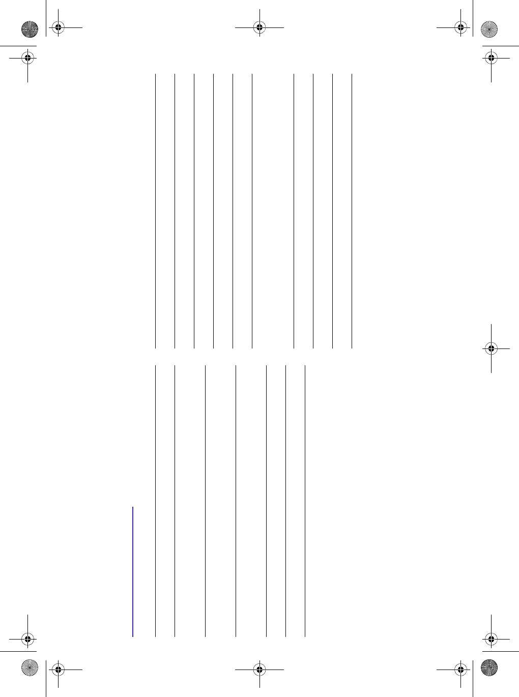
Check pack items
Wireless base station
Plan wireless keyboard system
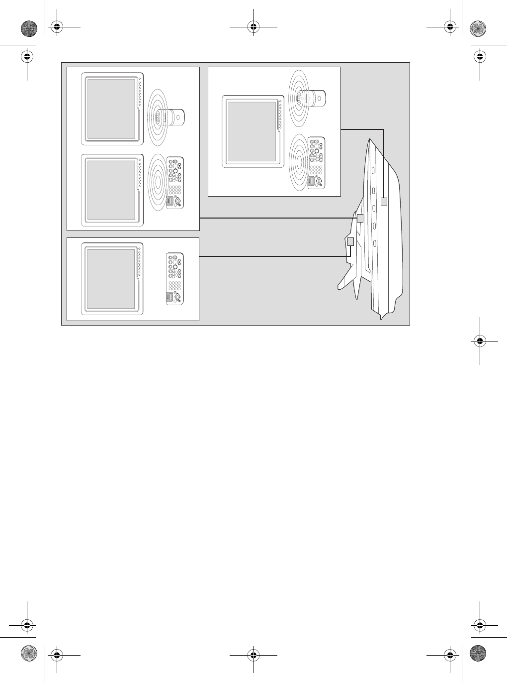
Typical system layout
The base station and wireless keyboard are installed as a part of the
Raymarine G-Series system.
Description Part No.
Wireless base station E02045
1 m (3.3 ft) SeaTalk NG spur cable - stripped ends A06043
400 mm (15.75 in) SeaTalkng backbone cable A06033
SeaTalk NG T-connector A06028
SeaTalkng backbone cable
SeaTalkng spur cable
SeaTalk T connector
D10067-2
SeaTalkng
wireless basestation
Monitor
Keyboard
SeaTalkng backbone
SeaTalkng spur
SeaTalkng
bulkead mounting
cable
SeaTalkng spur
GPM400
D10069-2
SeaTalkng charge cable
Basestation
Charge
point
9
WXYZ
8
TUV
7
PQRS
4
GHI
5
JKL
6
MNO
ACTIVE
WPTS
MOB
DATA
MENU
PAGE
.0
2
ABC
3
DEF
1
CANCEL
STANDBY
DODGE PILOT OK
RANGE
OUT
IN
ENTER
87086_1.book Page 3 Thursday, October 4, 2007 8:47 AM
4
Notes:
1. Each keyboard and base station communicate as a dedi-
cated pair.
2. You should have at least one permanently wired keyboard.
In the event that any wireless keyboards are lost, the wired
keyboard can be used to control the system.
3. When connecting a keyboard to the system, record its details
on your system diagram. You will need this information
during commissioning. (Refer to the separate G-Series
system installation instructions for sample diagrams.)
Wireless keyboard & base station cables
Charge keyboard
Charge for 6 hours
Before proceeding with the installation you must charge the
keyboard. If the SeaTalkng wiring is not installed, you will need to
create a temporary keyboard connection with power as shown.
See also
• For information on the keyboard battery and charge point. Refer
to separate instructions supplied with the wireless upgrade kit.
Cable Part No Notes
Wireless base station to SeaTalkng
1 m (3.3 ft)
SeaTalkng spur cable (bare ends)
A06043 Included with wireless base
station.
3 m (9.8 ft)
SeaTalkng spur cable (bare ends)
A06044
Keyboard charging
2.5 m (8.2 ft)
charging cable
R08311 Included with the wireless
upgrade kit.
3 m (9.8 ft)
SeaTalkng bulkhead mounting
cable
R08310
SeaTalkng power
12 Vdc to SeaTalkng A06049
12 V dc,
5 A fuse supply
D10688-1
G-Series Keyboard rear
SeaTalkng power cable
SeaTalkng spur
SeaTalkng backbone
87086_1.book Page 4 Thursday, October 4, 2007 8:47 AM
5
Site survey
A site survey is required to select the appropriate location for your
wireless base station. You must repeat the site survey for each
keyboard / base station pair.
Mounting and environment
• Do NOT install near sources of heat or vibration. (e.g. engine).
• Install in a dry area below decks.
• Mount on a vertical surface.
• Install the unit well away from potential sources of ignition.
• Mount at least 1 m (3 ft) away from devices which may be affect-
ed by radio transmission (e.g. compass).
Location
Select a location likely to provide the required wireless coverage.
E.g. In the immediate vicinity of single / co-located nav stations or
mid-way between remotely located nav stations.
D10687-1
Saloon
9
WXYZ
8
TUV
7
PQRS
4
GHI
5
JKL
6
MNO
ACTIVE
WPTS
MOB
DATA
MENU
PAGE
0
2
ABC
3
DEF
1
CANCEL
STANDBY
DODGE PILOT OK
RANGE
OUT
IN
ENTER
Flybridge
Wired keyboard
Monitor
Monitor
9
WXYZ
8
TUV
7
PQRS
4
GHI
5
JKL
6
MNO
ACTIVE
WPTS
MOB
DATA
MENU
PAGE
0
2
ABC
3
DEF
1
CANCEL
STANDBY
DODGE PILOT OK
RANGE
OUT
IN
ENTER
Wireless basestation
Wireless keyboard
9
WXYZ
8
TUV
7
PQRS
4
GHI
5
JKL
6
MNO
ACTIVE
WPTS
MOB
DATA
MENU
PAGE
0
2
ABC
3
DEF
1
CANCEL
STANDBY
DODGE PILOT OK
RANGE
OUT
IN
ENTER
Bridge
Wireless Basestation
Monitor Monitor
Wireless keyboard
87086_1.book Page 5 Thursday, October 4, 2007 8:47 AM
6
Check wireless coverage
You must survey the wireless coverage to ensure that each wireless
keyboard can operate in the intended area.
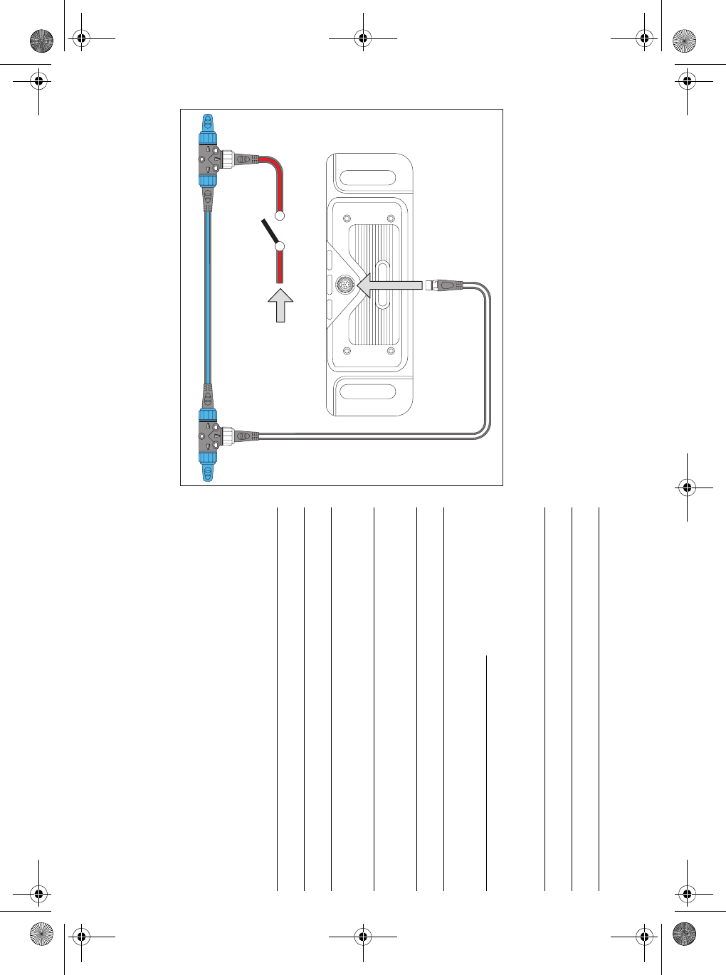
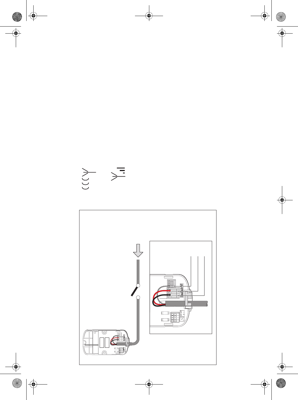
Connect power to base station
Site the base station at the required location and make a temporary
switched connection to the power supply.
Register Keyboard to base station
Register an unregistered keyboard to the required base station.
1. Turn off all base stations and keyboards within range.
2. Turn on the appropriate base station.
3. Within one minute turn on the unregistered keyboard.
(This must be within range of the base station.)
4. The keyboard attempts to register.
5. Once the base station is detected, the keyboard display shows
the signal strength.
e.g.
The keyboard is now registered.
Note: It is important that NO additional wireless keyboards or base
stations are turned on during registration. This will prevent
accidental registration of the wrong device or base station.
Check signal strength
1. Press the button (located under the outer cover of the base
station) to initiate site survey mode.
2. Slowly move the keyboard around the required area of the
vessel, confirming that the signal strength indicator maintains a
strong signal (i.e 3 bars).
3. If the signal strength is not maintained, re-position the base
station and repeat the survey.
4. Turn off the base station once the survey is complete.
D10689-1
Wireless
basestation
Black
Red
Temporary
power
connection
Screen
12 V dc,
5 A fuse supply
Power cable
87086_1.book Page 6 Thursday, October 4, 2007 8:47 AM
7
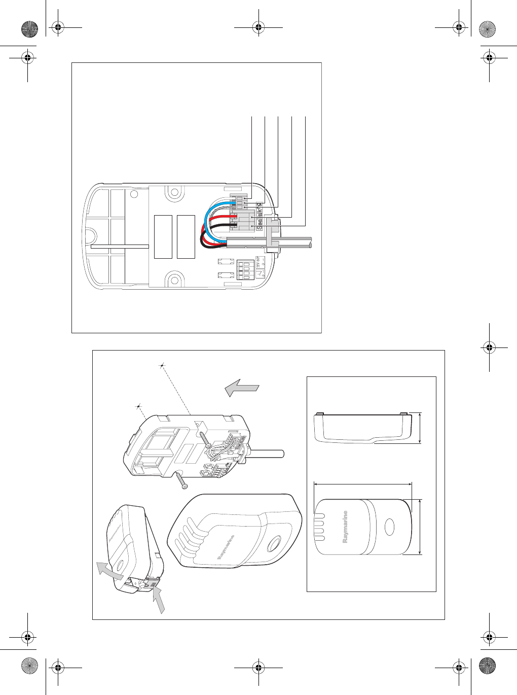
Mounting and connection
Wireless base station mounting
Wireless base station connections
Repeat base station
There are no repeat base stations for the wireless keyboard.
Keyboard and charge cable installation
For information on the wireless keyboard and charge cables, refer to
the separate instructions supplied with the wireless upgrade kit.
D10203-2
66 mm (2.6 in)
117 mm (4.61 in)
36 mm (1.42 in)
Mount
Vertically
D10208-1
Black
Red
Blue
White
Wireless
basestation
SeaTalkng
connection
Screen
87086_1.book Page 7 Thursday, October 4, 2007 8:47 AM
8
Wireless base station technical specification
Size 66 mm x 118 mm x 36mm
(2.6 in x 4.7 in x 1.4 in)
Mounting Surface mount
Supply voltage 9 V to 16 V
Power consumption 0.96 W
Transmitted power 1 mW
Environmental conditions: operating temperature: -15°C to 55°C (5°F to 131°F)
non-operating temperature: -25°C to 70°C (-13°F to
158°F)
relative humidity limit: 95%
Storage conditions when
packed:
Temperature: -20°C to 55°C (-4°F to 131°F)
relative humidity: 75%
Base station to keyboard
range
Typically 9 m (30 ft)
Approvals: Europe: R&TTE 1999/5/EC
USA: CFR47 Part 15
Canada: RSS-210
LEN 2
Raymarine plc
Anchorage Park,
Portsmouth,
Hampshire PO3 5TD
United Kingdom
Tel: +44 (0) 23 9269 3611
Fax: +44 (0) 23 9269 4642
Raymarine Inc.
21 Manchester Street,
Merrimack,
New Hampshire 03054-4801
USA
Tel: +1 603.881.5200
Fax: +1 603.864.4576
www.raymarine.com
87086_1.book Page 8 Thursday, October 4, 2007 8:47 AM