Flir BelgiumBA VHFGEN1 Fixed Mount VHF marine radio User Manual Ray218 55 Handbook
Raymarine UK Ltd. Fixed Mount VHF marine radio Ray218 55 Handbook
UserManual.wiki
>
Flir BelgiumBA
>
VHFGEN1 User Manual
>
Part user handbook
Contents
1.
Part user handbook
2.
Part2 user handbook
3.
Part3 user handbook
Part user handbook
Navigation menu
Upload a User Manual
Namespaces
Wiki Guide
HTML
PDF
Info
Views
User Manual
Discussion / Help
Navigation
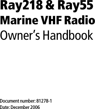

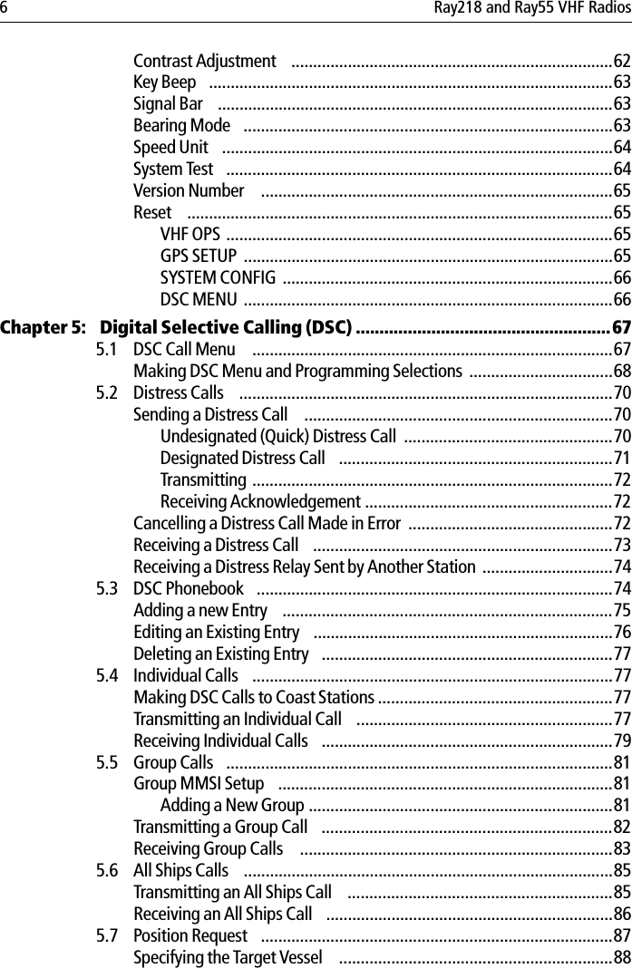

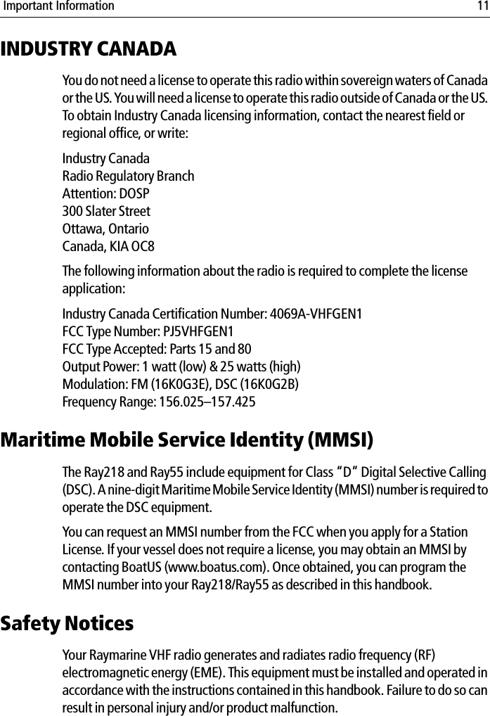
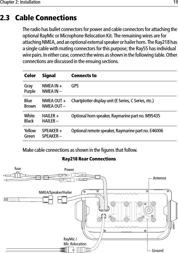
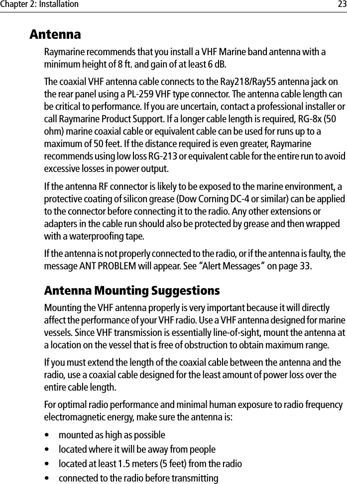
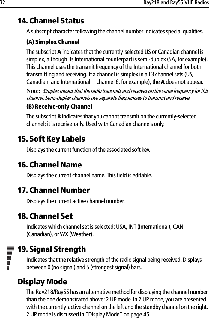
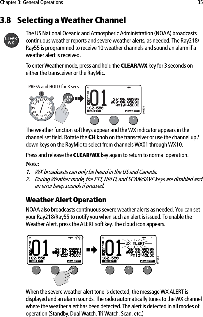
![40 Ray218 and Ray55 VHF RadiosTo make Menu selections:1. Press and release the MENU/DSC key to enter Menu mode. The list of avail-able menu groups appears. 2. Use the up/down arrow soft keys or CH knob on the transceiver or CH up/down key on microphone (or RayMic) to scroll through the list until the desired menu is highlighted. 3. Press SELECT or the CH knob on the transceiver or HILO key on microphone (or OK key on RayMic) to accept. The sub-menu headings are displayed. 4. Use the up/down arrow soft keys or the CH knob on the transceiver or CH up/down key on microphone (or RayMic) to highlight the desired sub-menu. 72SHIP/SHIPBBMAIN MENUSELECTVHF OPSHAIL/FOG/ICGPS SETUPSYSTM CONFIG[EXIT]USAD9163-172SHIP/SHIPBBMAIN MENUSELECTHAIL/FOG/ICGPS SETUPSYSTM CONFIGUSAD9164-1VHF OPS[EXIT]72SHIP/SHIPBBSYSTM CONFIGSELECTBACKLIGHTCONTRASTKEY BEEPSIGNAL BARBEARINGUSAD9165-172SHIP/SHIPBBSYSTM CONFIGSELECTBACKLIGHTCONTRASTKEY BEEPSIGNAL BARBEARINGUSAD9166-1](https://usermanual.wiki/Flir-BelgiumBA/VHFGEN1.Part-user-handbook/User-Guide-772921-Page-40.png)
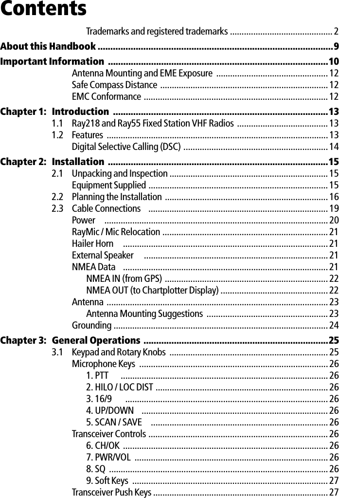
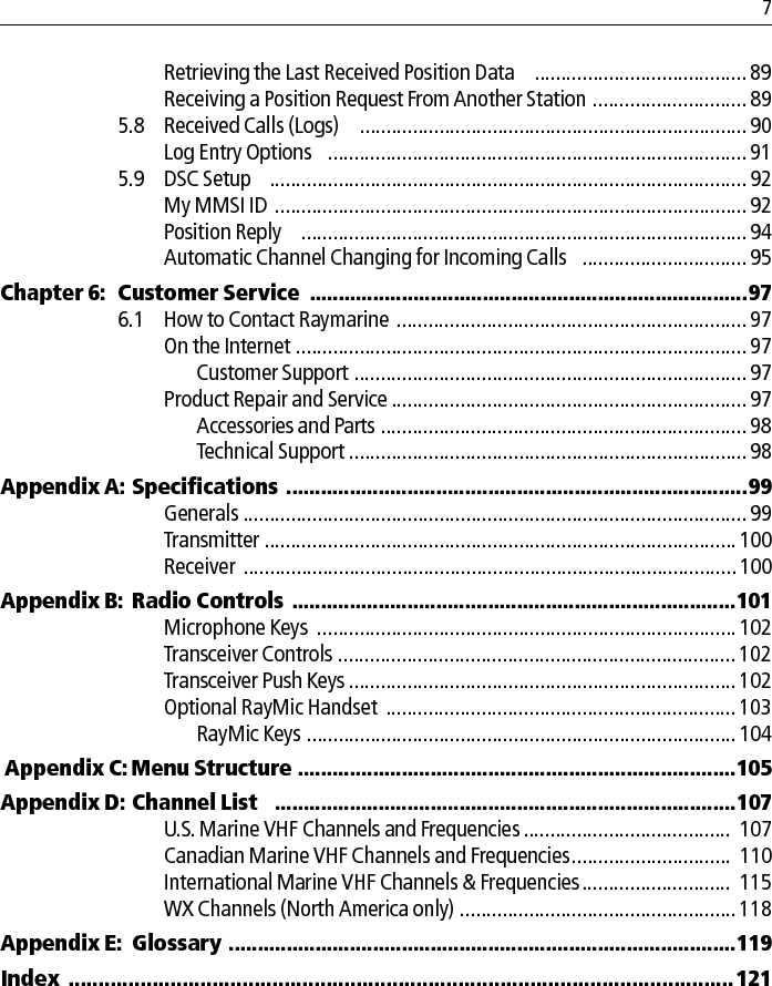
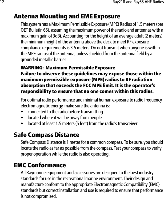
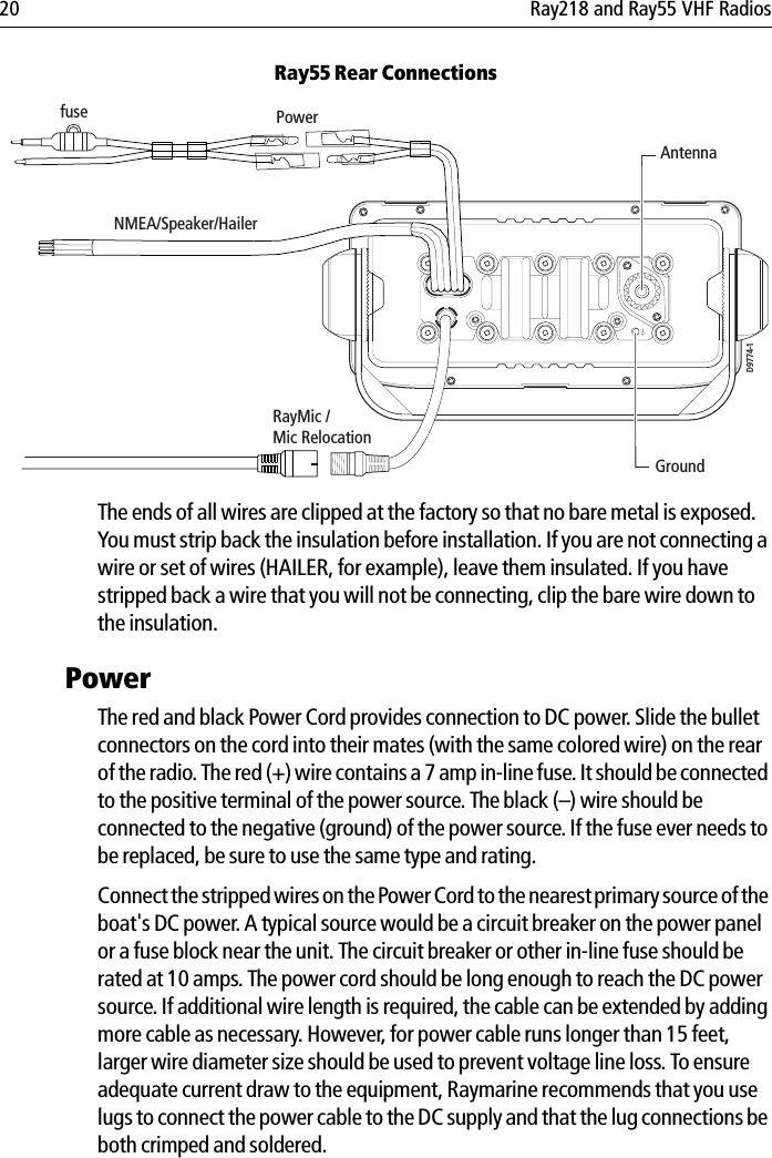
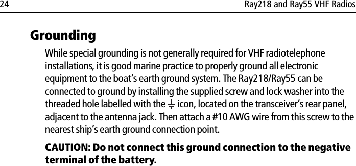
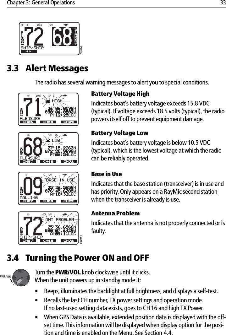
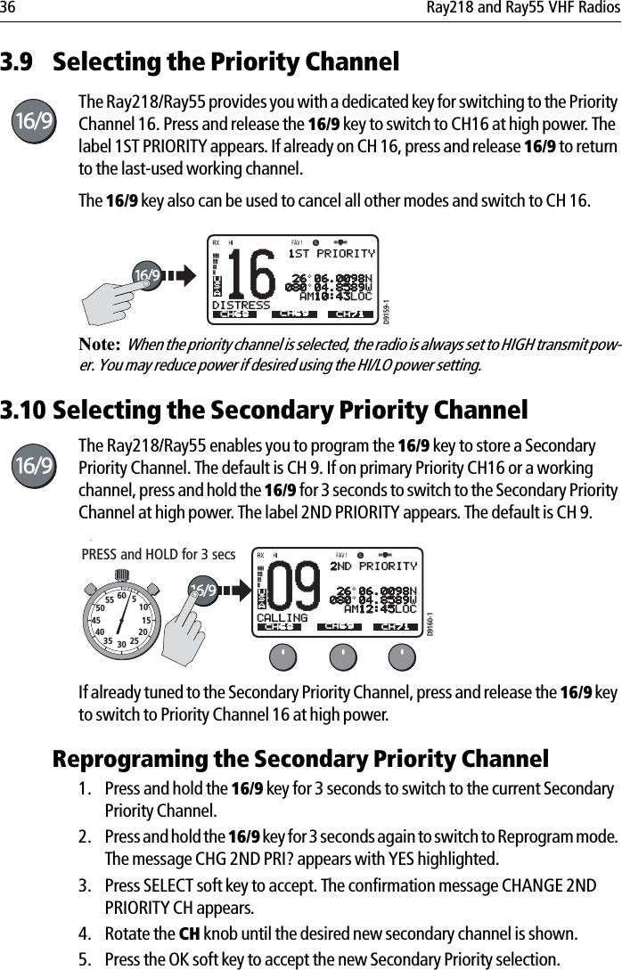
![Chapter 4: Menu Settings 415. Press SELECT or the CH knob on the transceiver or HILO key on microphone (or OK key on RayMic) to accept. The options under that sub-menu are dis-played. 6. Use the up/down arrow soft keys or the CH knob on the transceiver or CH up/down key on microphone (or RayMic) to highlight the desired option. 7. Press SELECT or the CH knob on the transceiver or HILO key on microphone (or OK key on RayMic) to accept. The setting is changed. Continue in the same manner to make any other setting changes. To return to the previous menu level, select the [BACK] menu option or press the CLEAR/WX key.To exit the Menu mode, press the CLEAR/WX key again or else press the 16/9 key to switch to the priority channel in standby mode.72SHIP/SHIPBBKEY BEEPSELECTLOUDQUIETOFF[BACK]USAD9167-172SHIP/SHIPBBKEY BEEPSELECTLOUDQUIETOFF[BACK]USAD9168-172SHIP/SHIPBBKEY BEEPSELECTLOUDQUIETOFF[BACK]USAD9169-1](https://usermanual.wiki/Flir-BelgiumBA/VHFGEN1.Part-user-handbook/User-Guide-772921-Page-41.png)
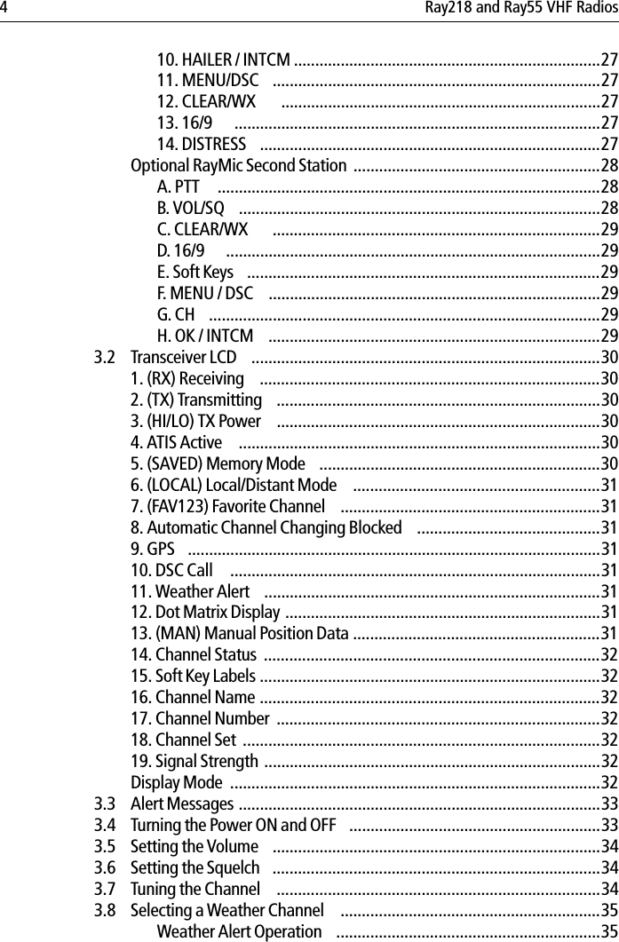
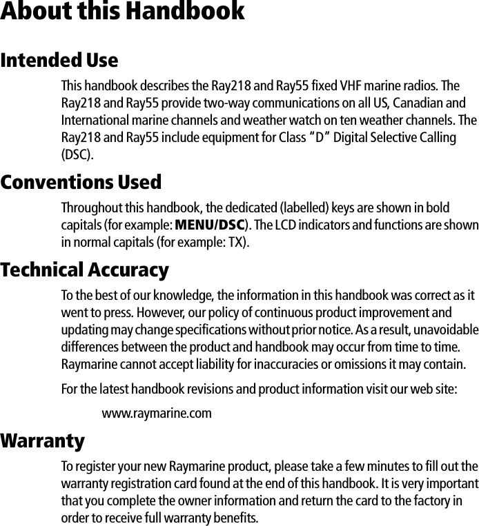
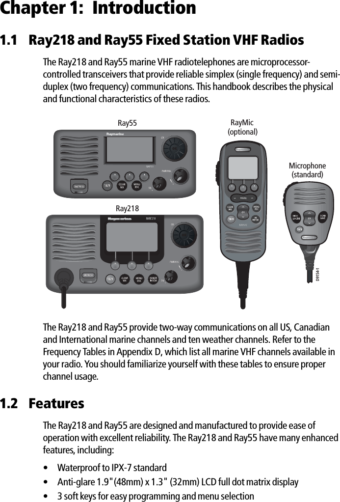
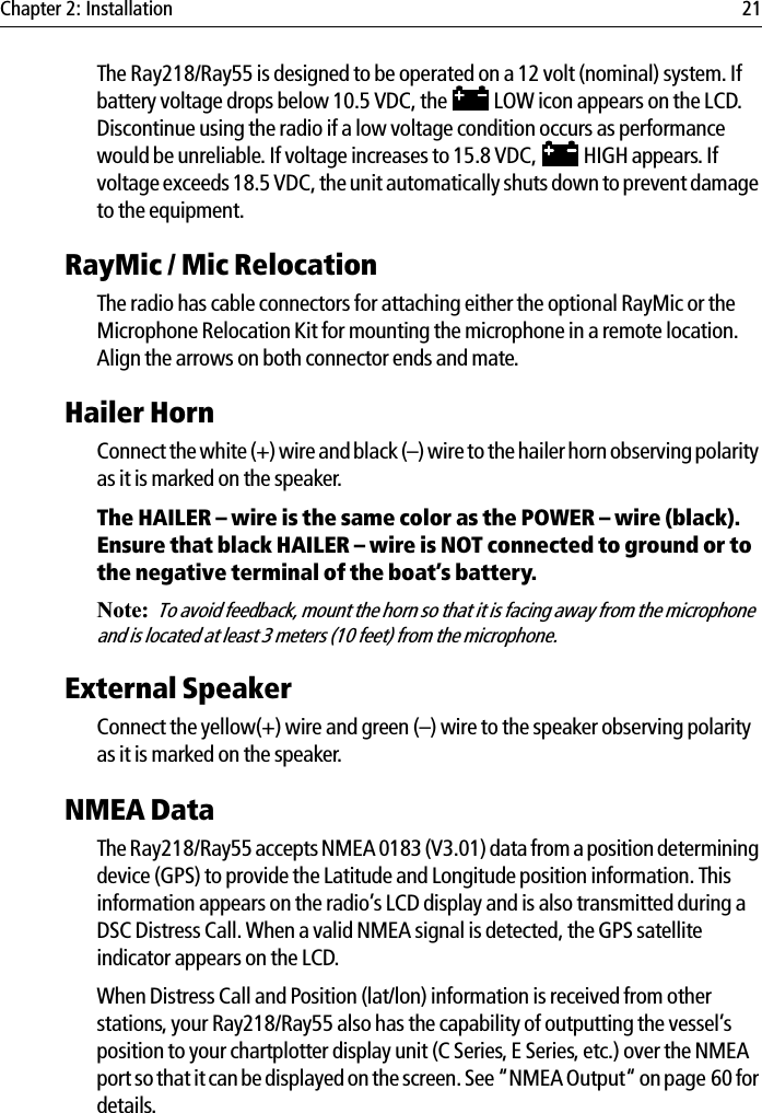
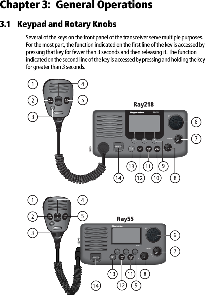
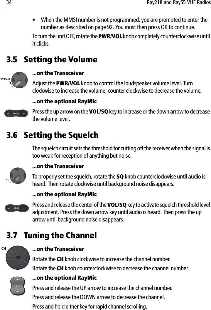
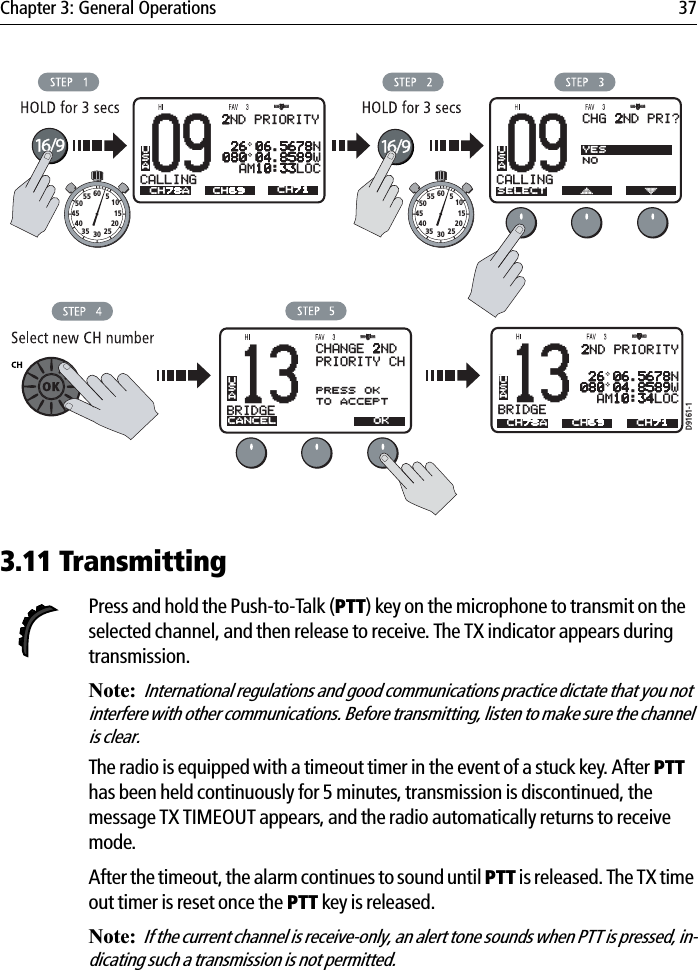
![42 Ray218 and Ray55 VHF Radios4.2 VHF OperationsThis menu group controls basic radio functions. You access VHF Operations via the MENU key. Scan ModeThis function automatically searches through all channels in the set for any that are broadcasting. If a transmission is received, the scan stops on the receiving channel as long as it is present. If the signal is lost for five seconds, the radio resumes scanning.If you wish to temporarily remove a received channel from the scan so that the scan no longer stops on this channel, press the XCLUDE soft key. The selected channel is only excluded for the time you are currently in scan mode.You can directly access the Scan Mode menu by pressing and releasing the SCAN/SAVE key on the microphone. When a Scan Mode is active, you can terminate the scan and return the radio to standby mode by pressing and releasing the key again.While scanning, press the microphone or RayMic CH up/down keys or rotate the CH knob on the transceiver to change the scan direction. UP (key)/clockwise (CHknob) increases the channel while DOWN (key) /counter-clockwise (CH knob) decreases it.Your Ray218/Ray55 is equipped with four types of scan options: All Scan, Saved (Memory) Scan, Priority All Scan and Priority Saved Scan. The following illustration demonstrates how to initiate All Scan but the procedure is the same for all scan mode options.Note: Whenever Weather Alert is activated, the WX Alert channel is also monitored dur-ing the Scan Modes. If the WX Alert tone is detected, the scan is halted to receive the Weather Alert broadcast.68PLEASUREBBMAIN MENUSELECTVHF OPSHAIL/FOG/ICGPS SETUPSYSTM CONFIG[BACK]USA68PLEASUREBBVHF OPSSELECTSCAN MODEDISPLAY MODEHI/LO POWERSAVE CHANNELWATCH MODEUSAD9170-1](https://usermanual.wiki/Flir-BelgiumBA/VHFGEN1.Part-user-handbook/User-Guide-772921-Page-42.png)
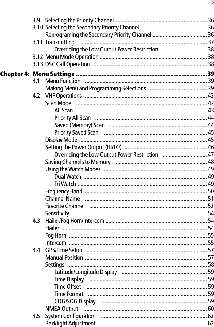
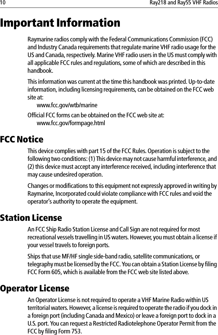
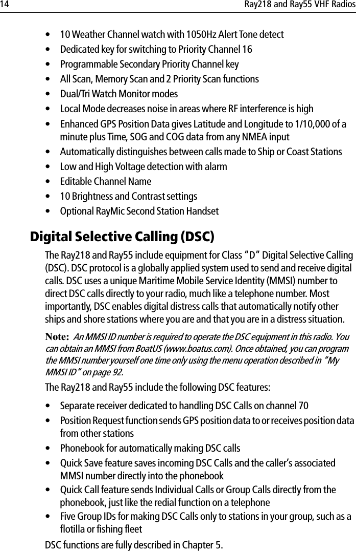
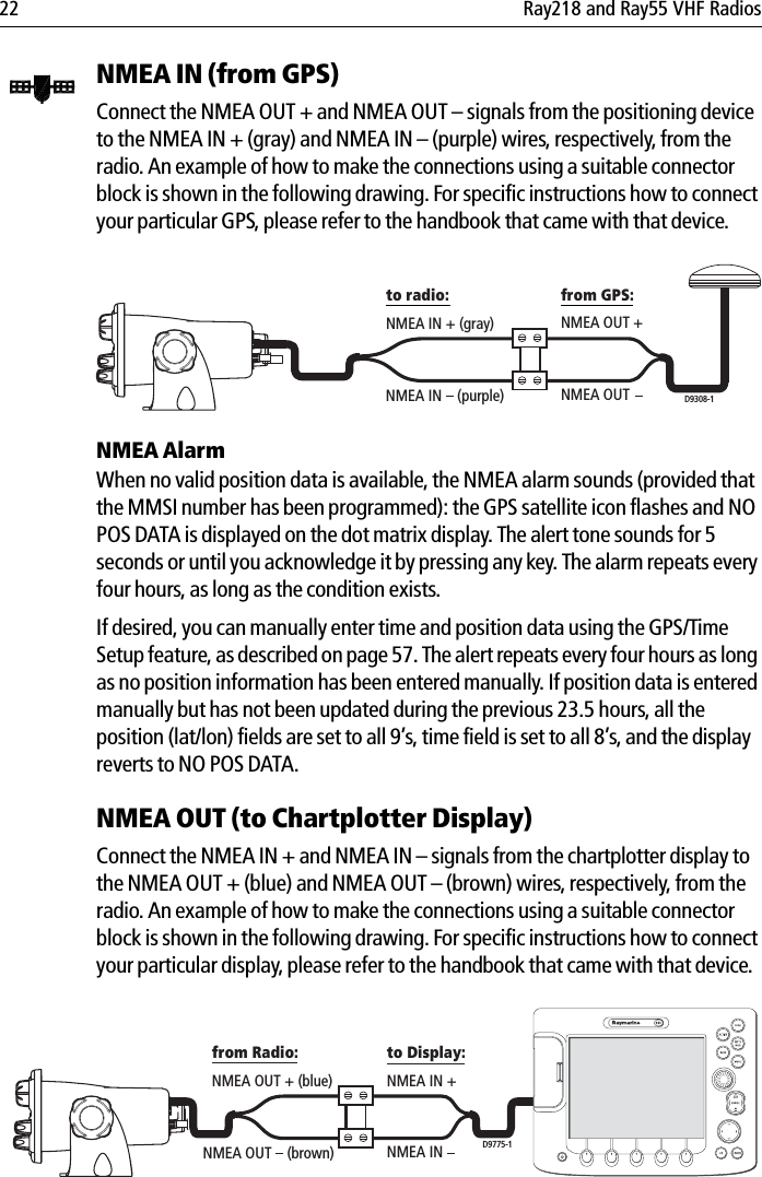
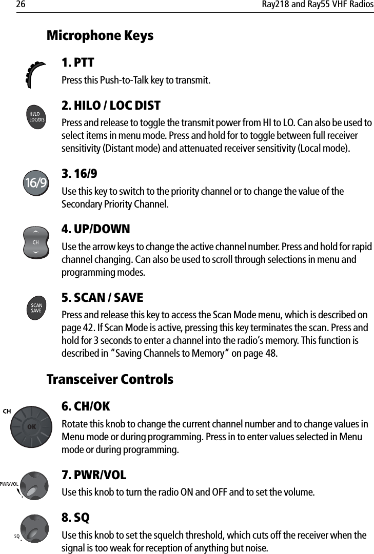
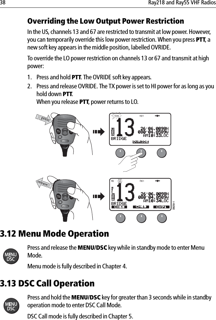
![Chapter 4: Menu Settings 43 To terminate the SCAN mode and return to standby mode, press:• END soft key•SCAN/SAVE key on the microphone•CLEAR/WX key on the transceiver•CLEAR/WX key on the optional RayMicAll ScanIn All Scan mode, all channels in the channel set are scanned in sequence. After the last channel number has been scanned, the cycle repeats.When active, SCAN ALL appears on the display. 71PLEASUREBBVHF OPSSELECTSCAN MODEDISPLAY MODEHI/LO POWERSAVE CHANNELWATCH MODEUSA71PLEASUREBBSCAN MODESELECTSCAN ALLSCAN ALL+16SCAN SAVESCAN SAVE+16[BACK]USAUSASCAN ALL 27 07.3838N080 04.8499W AM12:45LOCEND XCLUDED9171-1SCAN ALLUSA01SCAN ALLUSA88SCAN ALLUSA03SCAN ALLUSA07SCAN ALLUSA05SCAN ALLUSA06D9172-1](https://usermanual.wiki/Flir-BelgiumBA/VHFGEN1.Part-user-handbook/User-Guide-772921-Page-43.png)