Flir BelgiumBA VHFGEN1 Fixed Mount VHF marine radio User Manual Ray218 55 Handbook
Raymarine UK Ltd. Fixed Mount VHF marine radio Ray218 55 Handbook
Contents
- 1. Part user handbook
- 2. Part2 user handbook
- 3. Part3 user handbook
Part user handbook
Ray218 & Ray55
Marine VHF Radio
Owner’s Handbook
Document number: 81278-1
Date: December 2006
Trademarks and registered trademarks
Raymarine is a registered trademark of Raymarine plc.
All other product names are trademarks or registered trademarks of their
respective owners.
Contents of this handbook © Raymarine 2006
Contents
Trademarks and registered trademarks ............................................ 2
About this Handbook .............................................................................................9
Important Information .......................................................................................10
Antenna Mounting and EME Exposure ................................................12
Safe Compass Distance ........................................................................12
EMC Conformance ...............................................................................12
Chapter 1: Introduction .....................................................................................13
1.1 Ray218 and Ray55 Fixed Station VHF Radios .......................................13
1.2 Features ............................................................................................... 13
Digital Selective Calling (DSC) .............................................................. 14
Chapter 2: Installation .......................................................................................15
2.1 Unpacking and Inspection .................................................................... 15
Equipment Supplied ............................................................................. 15
2.2 Planning the Installation ......................................................................16
2.3 Cable Connections ............................................................................. 19
Power ................................................................................................ 20
RayMic / Mic Relocation ....................................................................... 21
Hailer Horn ........................................................................................21
External Speaker ...............................................................................21
NMEA Data ........................................................................................21
NMEA IN (from GPS) ......................................................................22
NMEA OUT (to Chartplotter Display) .............................................. 22
Antenna ............................................................................................... 23
Antenna Mounting Suggestions .................................................... 23
Grounding ............................................................................................24
Chapter 3: General Operations .........................................................................25
3.1 Keypad and Rotary Knobs .................................................................... 25
Microphone Keys .................................................................................26
1. PTT .........................................................................................26
2. HILO / LOC DIST ..........................................................................26
3. 16/9 .......................................................................................26
4. UP/DOWN ................................................................................ 26
5. SCAN / SAVE ............................................................................ 26
Transceiver Controls ............................................................................. 26
6. CH/OK ........................................................................................26
7. PWR/VOL ................................................................................... 26
8. SQ ..............................................................................................26
9. Soft Keys .................................................................................... 27
Transceiver Push Keys ...........................................................................27

4 Ray218 and Ray55 VHF Radios
10. HAILER / INTCM ........................................................................27
11. MENU/DSC .............................................................................27
12. CLEAR/WX ...........................................................................27
13. 16/9 ......................................................................................27
14. DISTRESS ................................................................................27
Optional RayMic Second Station ..........................................................28
A. PTT ..........................................................................................28
B. VOL/SQ .....................................................................................28
C. CLEAR/WX .............................................................................29
D. 16/9 ........................................................................................29
E. Soft Keys ...................................................................................29
F. MENU / DSC ..............................................................................29
G. CH ............................................................................................29
H. OK / INTCM ..............................................................................29
3.2 Transceiver LCD ..................................................................................30
1. (RX) Receiving ................................................................................30
2. (TX) Transmitting ............................................................................30
3. (HI/LO) TX Power ............................................................................30
4. ATIS Active .....................................................................................30
5. (SAVED) Memory Mode ..................................................................30
6. (LOCAL) Local/Distant Mode ..........................................................31
7. (FAV123) Favorite Channel .............................................................31
8. Automatic Channel Changing Blocked ...........................................31
9. GPS .................................................................................................31
10. DSC Call .......................................................................................31
11. Weather Alert ...............................................................................31
12. Dot Matrix Display ..........................................................................31
13. (MAN) Manual Position Data ..........................................................31
14. Channel Status ...............................................................................32
15. Soft Key Labels ................................................................................32
16. Channel Name ................................................................................32
17. Channel Number ............................................................................32
18. Channel Set ....................................................................................32
19. Signal Strength ...............................................................................32
Display Mode .......................................................................................32
3.3 Alert Messages .....................................................................................33
3.4 Turning the Power ON and OFF ...........................................................33
3.5 Setting the Volume .............................................................................34
3.6 Setting the Squelch .............................................................................34
3.7 Tuning the Channel ............................................................................34
3.8 Selecting a Weather Channel .............................................................35
Weather Alert Operation ..............................................................35

5
3.9 Selecting the Priority Channel .............................................................. 36
3.10 Selecting the Secondary Priority Channel ............................................. 36
Reprograming the Secondary Priority Channel ..................................... 36
3.11 Transmitting ....................................................................................... 37
Overriding the Low Output Power Restriction .............................. 38
3.12 Menu Mode Operation .........................................................................38
3.13 DSC Call Operation .............................................................................. 38
Chapter 4: Menu Settings ..................................................................................39
4.1 Menu Function ................................................................................... 39
Making Menu and Programming Selections ........................................ 39
4.2 VHF Operations ....................................................................................42
Scan Mode .........................................................................................42
All Scan ........................................................................................ 43
Priority All Scan ............................................................................ 44
Saved (Memory) Scan .................................................................. 44
Priority Saved Scan ...................................................................... 45
Display Mode ....................................................................................... 45
Setting the Power Output (HI/LO) ......................................................... 46
Overriding the Low Output Power Restriction .............................. 47
Saving Channels to Memory ..............................................................48
Using the Watch Modes ....................................................................... 49
Dual Watch ....................................................................................49
Tri Watch ........................................................................................49
Frequency Band .................................................................................... 50
Channel Name ................................................................................... 51
Favorite Channel ................................................................................52
Sensitivity .......................................................................................... 54
4.3 Hailer/Fog Horn/Intercom .....................................................................54
Hailer ................................................................................................... 54
Fog Horn .............................................................................................. 55
Intercom ...............................................................................................55
4.4 GPS/Time Setup ..................................................................................57
Manual Position ...................................................................................57
Settings ..............................................................................................58
Latitude/Longitude Display .......................................................... 59
Time Display ................................................................................59
Time Offset .................................................................................. 59
Time Format .................................................................................59
COG/SOG Display ........................................................................59
NMEA Output .................................................................................... 60
4.5 System Configuration ........................................................................ 62
Backlight Adjustment ........................................................................ 62

6 Ray218 and Ray55 VHF Radios
Contrast Adjustment ..........................................................................62
Key Beep .............................................................................................63
Signal Bar ...........................................................................................63
Bearing Mode .....................................................................................63
Speed Unit ..........................................................................................64
System Test .........................................................................................64
Version Number .................................................................................65
Reset ..................................................................................................65
VHF OPS .........................................................................................65
GPS SETUP .....................................................................................65
SYSTEM CONFIG ............................................................................66
DSC MENU .....................................................................................66
Chapter 5: Digital Selective Calling (DSC) ......................................................67
5.1 DSC Call Menu ...................................................................................67
Making DSC Menu and Programming Selections .................................68
5.2 Distress Calls ......................................................................................70
Sending a Distress Call .......................................................................70
Undesignated (Quick) Distress Call ................................................70
Designated Distress Call ...............................................................71
Transmitting ...................................................................................72
Receiving Acknowledgement .........................................................72
Cancelling a Distress Call Made in Error ...............................................72
Receiving a Distress Call .....................................................................73
Receiving a Distress Relay Sent by Another Station ..............................74
5.3 DSC Phonebook ..................................................................................74
Adding a new Entry ............................................................................75
Editing an Existing Entry .....................................................................76
Deleting an Existing Entry ...................................................................77
5.4 Individual Calls ...................................................................................77
Making DSC Calls to Coast Stations ......................................................77
Transmitting an Individual Call ...........................................................77
Receiving Individual Calls ...................................................................79
5.5 Group Calls .........................................................................................81
Group MMSI Setup .............................................................................81
Adding a New Group ......................................................................81
Transmitting a Group Call ...................................................................82
Receiving Group Calls ........................................................................83
5.6 All Ships Calls .....................................................................................85
Transmitting an All Ships Call .............................................................85
Receiving an All Ships Call ..................................................................86
5.7 Position Request .................................................................................87
Specifying the Target Vessel ...............................................................88

7
Retrieving the Last Received Position Data ........................................89
Receiving a Position Request From Another Station ............................. 89
5.8 Received Calls (Logs) ......................................................................... 90
Log Entry Options ............................................................................... 91
5.9 DSC Setup ..........................................................................................92
My MMSI ID ......................................................................................... 92
Position Reply ....................................................................................94
Automatic Channel Changing for Incoming Calls ............................... 95
Chapter 6: Customer Service ............................................................................97
6.1 How to Contact Raymarine ..................................................................97
On the Internet ..................................................................................... 97
Customer Support .......................................................................... 97
Product Repair and Service ................................................................... 97
Accessories and Parts .....................................................................98
Technical Support ...........................................................................98
Appendix A: Specifications ................................................................................99
Generals ...............................................................................................99
Transmitter ......................................................................................... 100
Receiver .............................................................................................100
Appendix B: Radio Controls .............................................................................101
Microphone Keys ...............................................................................102
Transceiver Controls ...........................................................................102
Transceiver Push Keys ......................................................................... 102
Optional RayMic Handset .................................................................. 103
RayMic Keys ................................................................................. 104
Appendix C: Menu Structure ............................................................................105
Appendix D: Channel List ................................................................................107
U.S. Marine VHF Channels and Frequencies ....................................... 107
Canadian Marine VHF Channels and Frequencies.............................. 110
International Marine VHF Channels & Frequencies............................ 115
WX Channels (North America only) ....................................................118
Appendix E: Glossary ........................................................................................119
Index ...............................................................................................................121

8 Ray218 and Ray55 VHF Radios
About this Handbook
Intended Use
This handbook describes the Ray218 and Ray55 fixed VHF marine radios. The
Ray218 and Ray55 provide two-way communications on all US, Canadian and
International marine channels and weather watch on ten weather channels. The
Ray218 and Ray55 include equipment for Class “D” Digital Selective Calling
(DSC).
Conventions Used
Throughout this handbook, the dedicated (labelled) keys are shown in bold
capitals (for example: MENU/DSC). The LCD indicators and functions are shown
in normal capitals (for example: TX).
Technical Accuracy
To the best of our knowledge, the information in this handbook was correct as it
went to press. However, our policy of continuous product improvement and
updating may change specifications without prior notice. As a result, unavoidable
differences between the product and handbook may occur from time to time.
Raymarine cannot accept liability for inaccuracies or omissions it may contain.
For the latest handbook revisions and product information visit our web site:
www.raymarine.com
Warranty
To register your new Raymarine product, please take a few minutes to fill out the
warranty registration card found at the end of this handbook. It is very important
that you complete the owner information and return the card to the factory in
order to receive full warranty benefits.

10 Ray218 and Ray55 VHF Radios
Important Information
Raymarine radios comply with the Federal Communications Commission (FCC)
and Industry Canada requirements that regulate marine VHF radio usage for the
US and Canada, respectively. Marine VHF radio users in the US must comply with
all applicable FCC rules and regulations, some of which are described in this
handbook.
This information was current at the time this handbook was printed. Up-to-date
information, including licensing requirements, can be obtained on the FCC web
site at:
www.fcc.gov/wtb/marine
Official FCC forms can be obtained on the FCC web site at:
www.fcc.gov/formpage.html
FCC Notice
This device complies with part 15 of the FCC Rules. Operation is subject to the
following two conditions: (1) This device may not cause harmful interference, and
(2) this device must accept any interference received, including interference that
may cause undesired operation.
Changes or modifications to this equipment not expressly approved in writing by
Raymarine, Incorporated could violate compliance with FCC rules and void the
operator’s authority to operate the equipment.
Station License
An FCC Ship Radio Station License and Call Sign are not required for most
recreational vessels travelling in US waters. However, you must obtain a license if
your vessel travels to foreign ports.
Ships that use MF/HF single side-band radio, satellite communications, or
telegraphy must be licensed by the FCC. You can obtain a Station License by filing
FCC Form 605, which is available from the FCC web site listed above.
Operator License
An Operator License is not required to operate a VHF Marine Radio within US
territorial waters. However, a license is required to operate the radio if you dock in
a foreign port (including Canada and Mexico) or leave a foreign port to dock in a
U.S. port. You can request a Restricted Radiotelephone Operator Permit from the
FCC by filing Form 753.

Important Information 11
INDUSTRY CANADA
You do not need a license to operate this radio within sovereign waters of Canada
or the US. You will need a license to operate this radio outside of Canada or the US.
To obtain Industry Canada licensing information, contact the nearest field or
regional office, or write:
Industry Canada
Radio Regulatory Branch
Attention: DOSP
300 Slater Street
Ottawa, Ontario
Canada, KIA OC8
The following information about the radio is required to complete the license
application:
Industry Canada Certification Number: 4069A-VHFGEN1
FCC Type Number: PJ5VHFGEN1
FCC Type Accepted: Parts 15 and 80
Output Power: 1 watt (low) & 25 watts (high)
Modulation: FM (16K0G3E), DSC (16K0G2B)
Frequency Range: 156.025–157.425
Maritime Mobile Service Identity (MMSI)
The Ray218 and Ray55 include equipment for Class “D” Digital Selective Calling
(DSC). A nine-digit Maritime Mobile Service Identity (MMSI) number is required to
operate the DSC equipment.
You can request an MMSI number from the FCC when you apply for a Station
License. If your vessel does not require a license, you may obtain an MMSI by
contacting BoatUS (www.boatus.com). Once obtained, you can program the
MMSI number into your Ray218/Ray55 as described in this handbook.
Safety Notices
Your Raymarine VHF radio generates and radiates radio frequency (RF)
electromagnetic energy (EME). This equipment must be installed and operated in
accordance with the instructions contained in this handbook. Failure to do so can
result in personal injury and/or product malfunction.

12 Ray218 and Ray55 VHF Radios
Antenna Mounting and EME Exposure
This system has a Maximum Permissible Exposure (MPE) Radius of 1.5 meters (per
OET Bulletin 65), assuming the maximum power of the radio and antennas with a
maximum gain of 3dBi. Accounting for the height of an average adult (2 meters)
the minimum height of the antenna above the deck to meet RF exposure
compliance requirements is 3.5 meters. Do not transmit when anyone is within
the MPE radius of the antenna, unless shielded from the antenna field by a
grounded metallic barrier.
WARNING: Maximum Permissible Exposure
Failure to observe these guidelines may expose those within the
maximum permissible exposure (MPE) radius to RF radiation
absorption that exceeds the FCC MPE limit. It is the operator’s
responsibility to ensure that no one comes within this radius.
For optimal radio performance and minimal human exposure to radio frequency
electromagnetic energy, make sure the antenna is:
• connected to the radio before transmitting
• located where it will be away from people
• located at least 1.5 meters (5 feet) from the radio’s transceiver
Safe Compass Distance
Safe Compass Distance is 1 meter for a common compass. To be sure, you should
locate the radio as far as possible from the compass. Test your compass to verify
proper operation while the radio is also operating.
EMC Conformance
All Raymarine equipment and accessories are designed to the best industry
standards for use in the recreational marine environment. Their design and
manufacture conform to the appropriate Electromagnetic Compatibility (EMC)
standards but correct installation and use is required to ensure that performance
is not compromised.
Chapter 1: Introduction
1.1 Ray218 and Ray55 Fixed Station VHF Radios
The Ray218 and Ray55 marine VHF radiotelephones are microprocessor-
controlled transceivers that provide reliable simplex (single frequency) and semi-
duplex (two frequency) communications. This handbook describes the physical
and functional characteristics of these radios.
The Ray218 and Ray55 provide two-way communications on all US, Canadian
and International marine channels and ten weather channels. Refer to the
Frequency Tables in Appendix D, which list all marine VHF channels available in
your radio. You should familiarize yourself with these tables to ensure proper
channel usage.
1.2 Features
The Ray218 and Ray55 are designed and manufactured to provide ease of
operation with excellent reliability. The Ray218 and Ray55 have many enhanced
features, including:
• Waterproof to IPX-7 standard
• Anti-glare 1.9"(48mm) x 1.3" (32mm) LCD full dot matrix display
• 3 soft keys for easy programming and menu selection
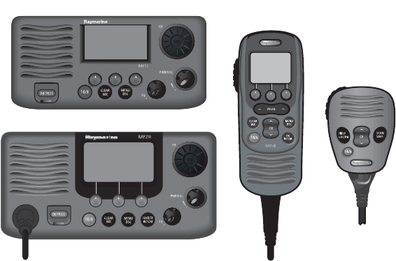
D9154-1
Ray55
Microphone
(standard)
RayMic
(optional)
Ray218

14 Ray218 and Ray55 VHF Radios
• 10 Weather Channel watch with 1050Hz Alert Tone detect
• Dedicated key for switching to Priority Channel 16
• Programmable Secondary Priority Channel key
• All Scan, Memory Scan and 2 Priority Scan functions
• Dual/Tri Watch Monitor modes
• Local Mode decreases noise in areas where RF interference is high
• Enhanced GPS Position Data gives Latitude and Longitude to 1/10,000 of a
minute plus Time, SOG and COG data from any NMEA input
• Automatically distinguishes between calls made to Ship or Coast Stations
• Low and High Voltage detection with alarm
• Editable Channel Name
• 10 Brightness and Contrast settings
• Optional RayMic Second Station Handset
Digital Selective Calling (DSC)
The Ray218 and Ray55 include equipment for Class “D” Digital Selective Calling
(DSC). DSC protocol is a globally applied system used to send and receive digital
calls. DSC uses a unique Maritime Mobile Service Identity (MMSI) number to
direct DSC calls directly to your radio, much like a telephone number. Most
importantly, DSC enables digital distress calls that automatically notify other
ships and shore stations where you are and that you are in a distress situation.
Note:
An MMSI ID number is required to operate the DSC equipment in this radio. You
can obtain an MMSI from BoatUS (www.boatus.com). Once obtained, you can program
the MMSI number yourself one time only using the menu operation described in “My
MMSI ID“ on page 92.
The Ray218 and Ray55 include the following DSC features:
• Separate receiver dedicated to handling DSC Calls on channel 70
• Position Request function sends GPS position data to or receives position data
from other stations
• Phonebook for automatically making DSC calls
• Quick Save feature saves incoming DSC Calls and the caller’s associated
MMSI number directly into the phonebook
• Quick Call feature sends Individual Calls or Group Calls directly from the
phonebook, just like the redial function on a telephone
• Five Group IDs for making DSC Calls only to stations in your group, such as a
flotilla or fishing fleet
DSC functions are fully described in Chapter 5.

Chapter 2: Installation
2.1 Unpacking and Inspection
Use care when unpacking the unit from the shipping carton to prevent damage to
the contents. It is also good practice to save the carton and the interior packing
material in the event you must return the unit to the factory.
Equipment Supplied
The following is a list of materials supplied with the Ray218 and Ray55:
Part No Description
E43032 Ray218 VHF Radio with removable microphone
R49163 Sun Cover for Ray218
R49164 Mounting Bracket for Ray218
R49165 Bracket Knob for Ray218/Ray55/Ray49
R49171 Microphone for Ray218
R49166 Microphone Hanger for Ray218/Ray55/Ray49
R49167 Power Cord for Ray218/Ray55/Ray49
R49168 NMEA/Speaker/Hailer Cable for Ray218
81278 Handbook for Ray218/Ray55
Screws (x5) for Mounting Bracket/Microphone Hanger
Screw/Lock Washer (x1) for Grounding
E43036 Ray55 VHF Radio with integral microphone
R49170 Sun Cover for Ray55
R49169 Mounting Bracket for Ray55
R49165 Bracket Knob for Ray218/Ray55/Ray49
R49166 Microphone Hanger for Ray218/Ray55
R49167 Power Cord for Ray218/Ray55/Ray49
81278 Handbook for Ray218/Ray55
Screws (x5) for Mounting Bracket/Microphone Hanger
Screw/Lock Washer (x1) for Grounding

16 Ray218 and Ray55 VHF Radios
The following is a list of optional equipment:
2.2 Planning the Installation
Mount the transceiver to allow easy access from the location where the boat is
normally navigated. Select a location that is non-metallic, dry, protected, well-
ventilated, and free from high operating temperatures and excessive vibration.
Provide sufficient space behind the transceiver to allow for proper cable
connections to the rear panel connectors. Locate the transceiver as near as
possible to the power source yet as far apart as possible from any devices that
may cause interference such as motors, generators, and other on board
electronics. The radio should be protected from prolonged direct exposure to rain
and salt spray.
The Ray218/Ray55 is not designed to be mounted in engine compartments. Do
not install the radio in a location where there may be flammable vapors (such as
in an engine room or compartment, or in a fuel tank bay), water splash or spray
from bilges or hatches, where it is at risk from physical damage from heavy items
(such as hatch covers, tool boxes, etc.), or where it might be covered by other
equipment. Locate the radio at least 1.5 meters from the antenna.
Safe Compass Distance is 1 meter for a common compass. To be sure, you should
locate the radio as far as possible from the compass. Test your compass to verify
proper operation while the radio is also operating.
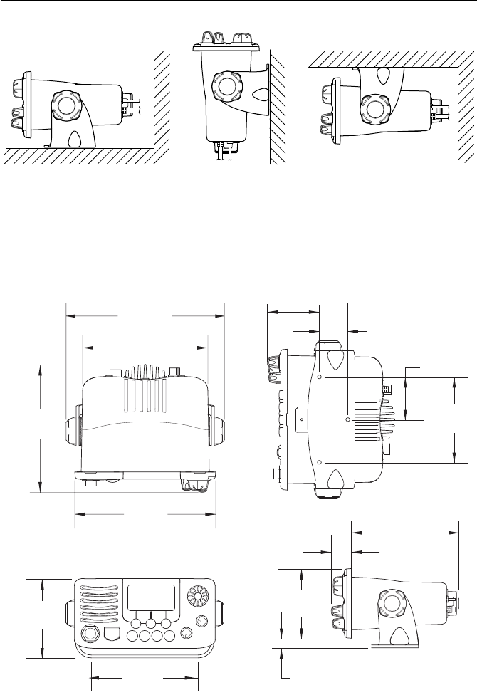
The Ray218/Ray55 can be conveniently mounted on a chart table, bulkhead,
overhead, or any other desired location. Refer to the following figure for typical
mounting methods.
Part No Description
A46051 RayMic Second Station for Ray218/Ray55
A46055 RayMic Extension Cable, 5m
A46056 RayMic Extension Cable, 10m
A46054 Microphone Relocation Kit for Ray218/Ray55
A46053 Rear Flush Mount Kit for Ray218/Ray55
A46060 Front Flush Mount Kit for Ray218
E46006 10W External Speaker
M95435 Hailer Horn Speaker
Chapter 2: Installation 17
The Ray218/Ray55 may also be flush mounted using the optional E46034 Flush
Mount Kit. Instructions for installing the radio using the Flush Mount Kit are
included with the kit, available from your Raymarine dealer.
Ray218 Dimensions
Table top mount Bulkhead mount Overhead mount
D9306-1
top bottom
D9309-1
8.76"
(222.4mm)
6.93"
(176mm)
7.06"
(179.3mm)
7.79"
(198mm)
4.43"
(112.5mm)
5.91"
(150mm)
5.94"
(151mm)
1.11"
(28.29mm)
0.59"
(15mm)
3.84"
(97.5mm)
4.72"
(120mm)
2.36"
(60mm)
1.57"
(40mm)
2.87"
(73mm)
18 Ray218 and Ray55 VHF Radios
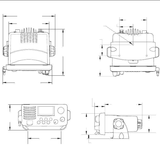
Ray55 Dimensions
top bottom
7.52" (191mm)
5.83" (148mm)
6.65"
(169mm)
7.09" (180mm)
3.94"
(100mm)
1.97"
(50mm)
D9305-1
R2.6
1.57"
(40mm)
2.96"
(75.3mm)
3.69"
(93.8mm) 3.04"
(77.2mm)
4.80"
(122mm)
5.35" (136mm)
0.59" (15.2mm)
2.51"
(63.7mm)
1.50" (38mm)
Chapter 2: Installation 19
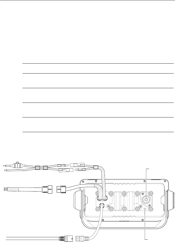
2.3 Cable Connections
The radio has bullet connectors for power and cable connectors for attaching the
optional RayMic or Microphone Relocation Kit. The remaining wires are for
attaching NMEA, and an optional external speaker or hailer horn. The Ray218 has
a single cable with mating connectors for this purpose; the Ray55 has individual
wire pairs. In either case, connect the wires as shown in the following table. Other
connections are discussed in the ensuing sections.
Make cable connections as shown in the figures that follow.
Ray218 Rear Connections
Color Signal Connects to
Gray
Purple
NMEA IN +
NMEA IN –
GPS
Blue
Brown
NMEA OUT +
NMEA OUT –
Chartplotter display unit (E Series, C Series, etc.)
White
Black
HAILER +
HAILER –
Optional horn speaker, Raymarine part no. M95435
Yellow
Green
SPEAKER +
SPEAKER –
Optional remote speaker, Raymarine part no. E46006
Antenna
Power
D9307-1
NMEA/Speaker/Hailer
fuse
RayMic /
Mic Relocation
Ground

20 Ray218 and Ray55 VHF Radios
Ray55 Rear Connections
The ends of all wires are clipped at the factory so that no bare metal is exposed.
You must strip back the insulation before installation. If you are not connecting a
wire or set of wires (HAILER, for example), leave them insulated. If you have
stripped back a wire that you will not be connecting, clip the bare wire down to
the insulation.
Power
The red and black Power Cord provides connection to DC power. Slide the bullet
connectors on the cord into their mates (with the same colored wire) on the rear
of the radio. The red (+) wire contains a 7 amp in-line fuse. It should be connected
to the positive terminal of the power source. The black (–) wire should be
connected to the negative (ground) of the power source. If the fuse ever needs to
be replaced, be sure to use the same type and rating.
Connect the stripped wires on the Power Cord to the nearest primary source of the
boat's DC power. A typical source would be a circuit breaker on the power panel
or a fuse block near the unit. The circuit breaker or other in-line fuse should be
rated at 10 amps. The power cord should be long enough to reach the DC power
source. If additional wire length is required, the cable can be extended by adding
more cable as necessary. However, for power cable runs longer than 15 feet,
larger wire diameter size should be used to prevent voltage line loss. To ensure
adequate current draw to the equipment, Raymarine recommends that you use
lugs to connect the power cable to the DC supply and that the lug connections be
both crimped and soldered.
Antenna
Power
NMEA/Speaker/Hailer
fuse
RayMic /
Mic Relocation
D9774-1
Ground

Chapter 2: Installation 21
The Ray218/Ray55 is designed to be operated on a 12 volt (nominal) system. If
battery voltage drops below 10.5 VDC, the LOW icon appears on the LCD.
Discontinue using the radio if a low voltage condition occurs as performance
would be unreliable. If voltage increases to 15.8 VDC, HIGH appears. If
voltage exceeds 18.5 VDC, the unit automatically shuts down to prevent damage
to the equipment.
RayMic / Mic Relocation
The radio has cable connectors for attaching either the optional RayMic or the
Microphone Relocation Kit for mounting the microphone in a remote location.
Align the arrows on both connector ends and mate.
Hailer Horn
Connect the white (+) wire and black (–) wire to the hailer horn observing polarity
as it is marked on the speaker.
The HAILER – wire is the same color as the POWER – wire (black).
Ensure that black HAILER – wire is NOT connected to ground or to
the negative terminal of the boat’s battery.
Note:
To avoid feedback, mount the horn so that it is facing away from the microphone
and is located at least 3 meters (10 feet) from the microphone.
External Speaker
Connect the yellow(+) wire and green (–) wire to the speaker observing polarity
as it is marked on the speaker.
NMEA Data
The Ray218/Ray55 accepts NMEA 0183 (V3.01) data from a position determining
device (GPS) to provide the Latitude and Longitude position information. This
information appears on the radio’s LCD display and is also transmitted during a
DSC Distress Call. When a valid NMEA signal is detected, the GPS satellite
indicator appears on the LCD.
When Distress Call and Position (lat/lon) information is received from other
stations, your Ray218/Ray55 also has the capability of outputting the vessel’s
position to your chartplotter display unit (C Series, E Series, etc.) over the NMEA
port so that it can be displayed on the screen. See “NMEA Output“ on page 60 for
details.
22 Ray218 and Ray55 VHF Radios
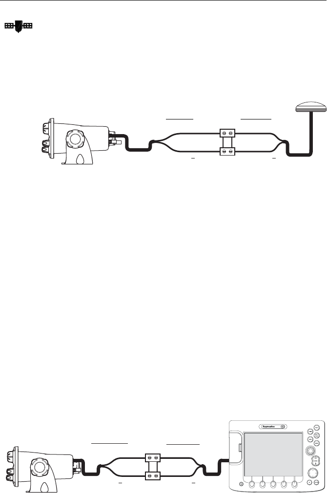
NMEA IN (from GPS)
Connect the NMEA OUT + and NMEA OUT – signals from the positioning device
to the NMEA IN + (gray) and NMEA IN – (purple) wires, respectively, from the
radio. An example of how to make the connections using a suitable connector
block is shown in the following drawing. For specific instructions how to connect
your particular GPS, please refer to the handbook that came with that device.
NMEA Alarm
When no valid position data is available, the NMEA alarm sounds (provided that
the MMSI number has been programmed): the GPS satellite icon flashes and NO
POS DATA is displayed on the dot matrix display. The alert tone sounds for 5
seconds or until you acknowledge it by pressing any key. The alarm repeats every
four hours, as long as the condition exists.
If desired, you can manually enter time and position data using the GPS/Time
Setup feature, as described on page 57. The alert repeats every four hours as long
as no position information has been entered manually. If position data is entered
manually but has not been updated during the previous 23.5 hours, all the
position (lat/lon) fields are set to all 9’s, time field is set to all 8’s, and the display
reverts to NO POS DATA.
NMEA OUT (to Chartplotter Display)
Connect the NMEA IN + and NMEA IN – signals from the chartplotter display to
the NMEA OUT + (blue) and NMEA OUT – (brown) wires, respectively, from the
radio. An example of how to make the connections using a suitable connector
block is shown in the following drawing. For specific instructions how to connect
your particular display, please refer to the handbook that came with that device.
D9308-1
NMEA IN + (gray) NMEA OUT +
NMEA OUT
to radio: from GPS:
NMEA IN (purple)
D9775-1
NMEA OUT + (blue)
NMEA OUT (brown)
NMEA IN +
NMEA IN
from Radio: to Display:

Chapter 2: Installation 23
Antenna
Raymarine recommends that you install a VHF Marine band antenna with a
minimum height of 8 ft. and gain of at least 6 dB.
The coaxial VHF antenna cable connects to the Ray218/Ray55 antenna jack on
the rear panel using a PL-259 VHF type connector. The antenna cable length can
be critical to performance. If you are uncertain, contact a professional installer or
call Raymarine Product Support. If a longer cable length is required, RG-8x (50
ohm) marine coaxial cable or equivalent cable can be used for runs up to a
maximum of 50 feet. If the distance required is even greater, Raymarine
recommends using low loss RG-213 or equivalent cable for the entire run to avoid
excessive losses in power output.
If the antenna RF connector is likely to be exposed to the marine environment, a
protective coating of silicon grease (Dow Corning DC-4 or similar) can be applied
to the connector before connecting it to the radio. Any other extensions or
adapters in the cable run should also be protected by grease and then wrapped
with a waterproofing tape.
If the antenna is not properly connected to the radio, or if the antenna is faulty, the
message ANT PROBLEM will appear. See “Alert Messages“ on page 33.
Antenna Mounting Suggestions
Mounting the VHF antenna properly is very important because it will directly
affect the performance of your VHF radio. Use a VHF antenna designed for marine
vessels. Since VHF transmission is essentially line-of-sight, mount the antenna at
a location on the vessel that is free of obstruction to obtain maximum range.
If you must extend the length of the coaxial cable between the antenna and the
radio, use a coaxial cable designed for the least amount of power loss over the
entire cable length.
For optimal radio performance and minimal human exposure to radio frequency
electromagnetic energy, make sure the antenna is:
• mounted as high as possible
• located where it will be away from people
• located at least 1.5 meters (5 feet) from the radio
• connected to the radio before transmitting

24 Ray218 and Ray55 VHF Radios
Grounding
While special grounding is not generally required for VHF radiotelephone
installations, it is good marine practice to properly ground all electronic
equipment to the boat’s earth ground system. The Ray218/Ray55 can be
connected to ground by installing the supplied screw and lock washer into the
threaded hole labelled with the icon, located on the transceiver’s rear panel,
adjacent to the antenna jack. Then attach a #10 AWG wire from this screw to the
nearest ship’s earth ground connection point.
CAUTION: Do not connect this ground connection to the negative
terminal of the battery.
Chapter 3: General Operations
3.1 Keypad and Rotary Knobs
Several of the keys on the front panel of the transceiver serve multiple purposes.
For the most part, the function indicated on the first line of the key is accessed by
pressing that key for fewer than 3 seconds and then releasing it. The function
indicated on the second line of the key is accessed by pressing and holding the key
for greater than 3 seconds.
Ray218
D9155-1
Ray55
D9304-1
26 Ray218 and Ray55 VHF Radios
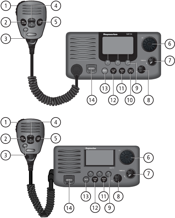
Microphone Keys
1. PTT
Press this Push-to-Talk key to transmit.
2. HILO / LOC DIST
Press and release to toggle the transmit power from HI to LO. Can also be used to
select items in menu mode. Press and hold for to toggle between full receiver
sensitivity (Distant mode) and attenuated receiver sensitivity (Local mode).
3. 16/9
Use this key to switch to the priority channel or to change the value of the
Secondary Priority Channel.
4. UP/DOWN
Use the arrow keys to change the active channel number. Press and hold for rapid
channel changing. Can also be used to scroll through selections in menu and
programming modes.
5. SCAN / SAVE
Press and release this key to access the Scan Mode menu, which is described on
page 42. If Scan Mode is active, pressing this key terminates the scan. Press and
hold for 3 seconds to enter a channel into the radio’s memory. This function is
described in “Saving Channels to Memory“ on page 48.
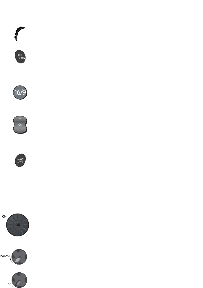
Transceiver Controls
6. CH/OK
Rotate this knob to change the current channel number and to change values in
Menu mode or during programming. Press in to enter values selected in Menu
mode or during programming.
7. PWR/VOL
Use this knob to turn the radio ON and OFF and to set the volume.
8. SQ
Use this knob to set the squelch threshold, which cuts off the receiver when the
signal is too weak for reception of anything but noise.

Chapter 3: General Operations 27
9. Soft Keys
These multifunction keys change according to context, such as to navigate
through menus or to make menu selections. Press to select the corresponding
function as identified by the on-screen label.
Transceiver Push Keys
10. HAILER / INTCM
Press and release to access the hailer horn to make voice announcements or
sound various fog horn tones. Press and hold for 3 seconds to use the intercom
feature to communicate with a secondary station. Requires an optional RayMic
second station.
This key is only available with the Ray218.
11. MENU/DSC
Press and release this key to select Menu Mode, which is used to set up the radio.
Menu operations are fully described in Chapter 4.
Press and hold for 3 seconds to enter DSC Call Mode, which is used for making
DSC Calls and viewing the DSC Call Logs and the DSC Call Phonebook.
A Maritime Mobile Service Identity (MMSI) number is required to operate the DSC
equipment in this radio. This number directs DSC calls directly to your radio, much
like a telephone number. You can program the MMSI number yourself one time
only using the operation described in “My MMSI ID“ on page 92. Otherwise, your
Raymarine dealer can program or change the number for you.
Full details on DSC call operation are described in Chapter 5.
12. CLEAR/WX
Press and release to terminate a function and return to the last-used channel.
Press and hold for 3 seconds to select the Weather mode.
13. 16/9
Use this key to switch to the priority channel or to change the value of the
Secondary Priority Channel.
14. DISTRESS
Push up the spring-loaded cover and press this key to make a DSC Distress Call.
Instructions for making a Distress Call are described in Section 5.2.
28 Ray218 and Ray55 VHF Radios
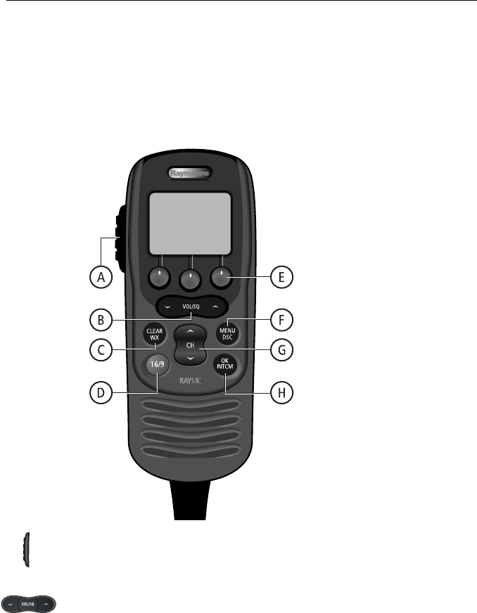
Optional RayMic Second Station
The optional RayMic Handset provides the Ray218/Ray55 with a second station
in a telephone handset design. The RayMic, which attaches to the handset
connector on the rear of the radio, enables intercom capabilities with the
transceiver from a remote portion of the vessel. Intercom functions are discussed
on page 55.
A. PTT
Press this Push-to-Talk key to transmit.
B. VOL/SQ
By default, these keys control earpiece speaker volume. Press the up arrow key to
increase or the down arrow to decrease the volume.
Press and release the center key to activate the squelch threshold adjustment.
Then, press up arrow key to increase or down arrow to decrease the squelch level.
D9253-1

Chapter 3: General Operations 29
C. CLEAR/WX
Press and release to terminate a function and return to the last-used channel.
Press and hold for 3 seconds to select the Weather mode.
D. 16/9
Press and release this key to switch between the Priority Channel 16 and the
current working channel.
Press and hold for 3 seconds to tune to the Secondary Priority Channel, which
defaults to 9.
If already tuned to the Secondary Priority Channel, press and hold for 3 seconds to
program a new Secondary Priority Channel.
E. Soft Keys
These multifunction keys change according to context, such as to navigate
through menus or to make menu selections. Press to select the corresponding
function as identified by the on-screen label.
F. MENU / DSC
Press and release this key to select Menu Mode, which is used to set up the radio.
The menu structure is outlined in the following drawing. Menu operations are
fully described in Chapter 4.
Press and hold for 3 seconds to enter DSC Call Mode, which is used for making
DSC Calls and viewing the DSC Call Logs and the DSC Call Phonebook.
G. CH
Use the arrow keys to change the active channel number. Press and hold for rapid
channel changing. Can also be used to scroll through selections in menu and
programming modes.
H. OK / INTCM
Press and release this key to enter values selected in Menu mode or during
programming. Press and hold for 3 seconds to enable the intercom feature for
communications between the transceiver and RayMic second station. Intercom
functions are discussed on page 55.
30 Ray218 and Ray55 VHF Radios
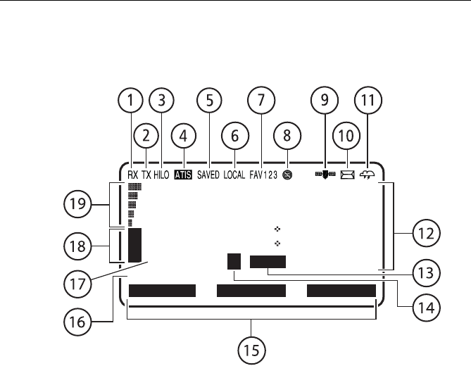
3.2 Transceiver LCD
The following describes the function of the characters on the radio’s LCD.
1. (RX) Receiving
Indicates that the radio is receiving a radio signal.
2. (TX) Transmitting
Indicates the PTT key is being pressed and the radio is transmitting.
3. (HI/LO) TX Power
Indicates whether transmit power is set for 25 watts (HI) or 1 watt (LO).
4. ATIS Active
Indicates ATIS transmission is enabled. Only available in European countries
using the International channel set.
5. (SAVED) Memory Mode
Indicates the current channel has been saved in memory. Appears during Saved
(Memory) Scan and Priority Saved Scan modes.
88
CH HAS BEEN
26 06.0098N
080 04.8589W
20:45UTC
COMMERCL
A
MAN
CH68
U
S
A
CH69 CH71
D9156-1

Chapter 3: General Operations 31
6. (LOCAL) Local/Distant Mode
Indicates the radio is in Local Reception mode, which decreases receiver
sensitivity in high traffic areas to decrease unwanted reception.
7. (FAV123) Favorite Channel
Indicates which of the three (3) Favorite Channel banks is currently selected. Each
bank displays a different favorite channel that you have assigned for each of the 3
soft key labels at the bottom of the LCD. This gives you a total of 9 favorite
channels that you can jump to at the press of a key.
8. Automatic Channel Changing Blocked
Indicates that your radio will not automatically switch to the channel requested
by an incoming DSC call but rather will prompt you to manually accept or decline
the channel change request. Applies to Distress and All Ships Urgency calls only.
This feature is controlled by the DSC Setup menu item POS REPLY, described on
page 95. By default, this icon is off, meaning that auto channel changing is active.
9. GPS
Indicates that positional data is available from your GPS.
10. DSC Call
When flashing, indicates that the radio has received a DSC Call. Details of the call
can be viewed in the associated log. See “Received Calls (Logs)” on page 90. The
icon disappears when the call is accepted, the call is rejected, or the associated
message is viewed in the log.
11. Weather Alert
Indicates that the radio is monitoring for weather alert broadcasts.
12. Dot Matrix Display
Indicates radio functions, GPS position data or special conditions, depending on
the situation. The screen is different when sending/receiving a DSC Call (see
Chapter 5) or setting up a Menu item (see Chapter 4).
13. (MAN) Manual Position Data
Indicates position data is not from GPS but rather has been entered manually.

32 Ray218 and Ray55 VHF Radios
14. Channel Status
A subscript character following the channel number indicates special qualities.
(A) Simplex Channel
The subscript A indicates that the currently-selected US or Canadian channel is
simplex, although its International counterpart is semi-duplex (5A, for example).
This channel uses the transmit frequency of the International channel for both
transmitting and receiving. If a channel is simplex in all 3 channel sets (US,
Canadian, and International—channel 6, for example), the A does not appear.
Note:
Simplex means that the radio transmits and receives on the same frequency for this
channel. Semi-duplex channels use separate frequencies to transmit and receive.
(B) Receive-only Channel
The subscript B indicates that you cannot transmit on the currently-selected
channel; it is receive-only. Used with Canadian channels only.
15. Soft Key Labels
Displays the current function of the associated soft key.
16. Channel Name
Displays the current channel name. This field is editable.
17. Channel Number
Displays the current active channel number.
18. Channel Set
Indicates which channel set is selected: USA, INT (International), CAN
(Canadian), or WX (Weather).
19. Signal Strength
Indicates that the relative strength of the radio signal being received. Displays
between 0 (no signal) and 5 (strongest signal) bars.
Display Mode
The Ray218/Ray55 has an alternative method for displaying the channel number
than the one demonstrated above: 2 UP mode. In 2 UP mode, you are presented
with the currently-active channel on the left and the standby channel on the right.
2 UP mode is discussed in “Display Mode” on page 45.
Chapter 3: General Operations 33
3.3 Alert Messages
The radio has several warning messages to alert you to special conditions.
Battery Voltage High
Indicates boat’s battery voltage exceeds 15.8 VDC
(typical). If voltage exceeds 18.5 volts (typical), the radio
powers itself off to prevent equipment damage.
Battery Voltage Low
Indicates boat’s battery voltage is below 10.5 VDC
(typical), which is the lowest voltage at which the radio
can be reliably operated.
Base in Use
Indicates that the base station (transceiver) is in use and
has priority. Only appears on a RayMic second station
when the transceiver is already is use.
Antenna Problem
Indicates that the antenna is not properly connected or is
faulty.
3.4 Turning the Power ON and OFF
Turn the PWR/VOL knob clockwise until it clicks.
When the unit powers up in standby mode it:
• Beeps, illuminates the backlight at full brightness, and displays a self-test.
• Recalls the last CH number, TX power settings and operation mode.
If no last-used setting data exists, goes to CH 16 and high TX Power.
• When GPS Data is available, extended position data is displayed with the off-
set time. This information will be displayed when display option for the posi-
tion and time is enabled on the Menu. See Section 4.4.
68
B
S
T
A
N
D
B
Y
72
SHIP/SHIP
B
B
U
S
A
D9312-1
68
PLEASURE
B
A
U
S
A
A
CH67 CH72CH68
LOW
71
PLEASURE
B
A
U
S
A
A
26 06.0098N
080 04.8582W
PM12:25LOC
CH06 CH09CH08
HIGH
27 15.2263N
078 20.9699W
PM06:54LOC
D9249-1
72
SHIP/SHIP
B
A
U
S
A
A
CH67 CH72CH68
ANT PROBLEM
09
CALLING
B
A
U
S
A
A
25 36.5658N
076 45.6785W
AM10:33LOC
CH67 CH72CH68
BASE IN USE
25 36.6566N
080 07.6439W
AM09:11LOC
34 Ray218 and Ray55 VHF Radios
• When the MMSI number is not programmed, you are prompted to enter the
number as described on page 92. You must then press OK to continue.
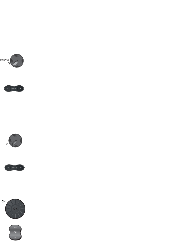
To turn the unit OFF, rotate the PWR/VOL knob completely counterclockwise until
it clicks.
3.5 Setting the Volume
...on the Transceiver
Adjust the PWR/VOL knob to control the loudspeaker volume level. Turn
clockwise to increase the volume; counter clockwise to decrease the volume.
...on the optional RayMic
Press the up arrow on the VOL/SQ key to increase or the down arrow to decrease
the volume level.
3.6 Setting the Squelch
The squelch circuit sets the threshold for cutting off the receiver when the signal is
too weak for reception of anything but noise.
...on the Transceiver
To properly set the squelch, rotate the SQ knob counterclockwise until audio is
heard. Then rotate clockwise until background noise disappears.
...on the optional RayMic
Press and release the center of the VOL/SQ key to activate squelch threshold level
adjustment. Press the down arrow key until audio is heard. Then press the up
arrow until background noise disappears.
3.7 Tuning the Channel
...on the Transceiver
Rotate the CH knob clockwise to increase the channel number.
Rotate the CH knob counterclockwise to decrease the channel number.
...on the optional RayMic
Press and release the UP arrow to increase the channel number.
Press and release the DOWN arrow to decrease the channel.
Press and hold either key for rapid channel scrolling.
Chapter 3: General Operations 35
3.8 Selecting a Weather Channel
The US National Oceanic and Atmospheric Administration (NOAA) broadcasts
continuous weather reports and severe weather alerts, as needed. The Ray218/
Ray55 is programmed to receive 10 weather channels and sound an alarm if a
weather alert is received.
To enter Weather mode, press and hold the CLEAR/WX key for 3 seconds on
either the transceiver or the RayMic.
The weather function soft keys appear and the WX indicator appears in the
channel set field. Rotate the CH knob on the transceiver or use the channel up /
down keys on the RayMic to select from channels WX01 through WX10.
Press and release the CLEAR/WX key again to return to normal operation.
Note:
1. WX broadcasts can only be heard in the US and Canada.
2. During Weather mode, the PTT, HI/LO, and SCAN/SAVE keys are disabled and
an error beep sounds if pressed.
Weather Alert Operation
NOAA also broadcasts continuous severe weather alerts as needed. You can set
your Ray218/Ray55 to notify you when such an alert is issued. To enable the
Weather Alert, press the ALERT soft key. The cloud icon appears.
When the severe weather alert tone is detected, the message WX ALERT is
displayed and an alarm sounds. The radio automatically tunes to the WX channel
where the weather alert has been detected. The alert is detected in all modes of
operation (Standby, Dual Watch, Tri Watch, Scan, etc.)
01
TW 16+09+W01
26 06.0098N
080 04.8589W
AM10:45LOC
162.550
A
EXIT CH79A ALERT
W
X
D9157-1
PRESS and HOLD for 3 secs
10
15
20
25
30
35
40
45
50
55 60 5
01
TW 16+09+W01
26 06.0098N
080 04.8589W
PM12:45LOC
162.550
A
EXIT CH79A ALERT
W
X
01
WX ALERT
26 06.0098N
080 04.8589W
PM12:45LOC
162.550
A
EXIT CH79A ALERT
W
X
D9158-1
36 Ray218 and Ray55 VHF Radios
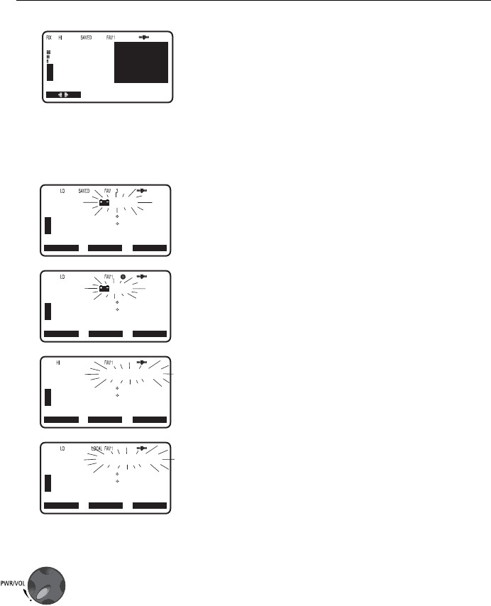
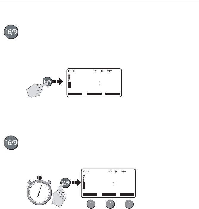
3.9 Selecting the Priority Channel
The Ray218/Ray55 provides you with a dedicated key for switching to the Priority
Channel 16. Press and release the 16/9 key to switch to CH16 at high power. The
label 1ST PRIORITY appears. If already on CH 16, press and release 16/9 to return
to the last-used working channel.
The 16/9 key also can be used to cancel all other modes and switch to CH 16.
Note:
When the priority channel is selected, the radio is always set to HIGH transmit pow-
er. You may reduce power if desired using the HI/LO power setting.
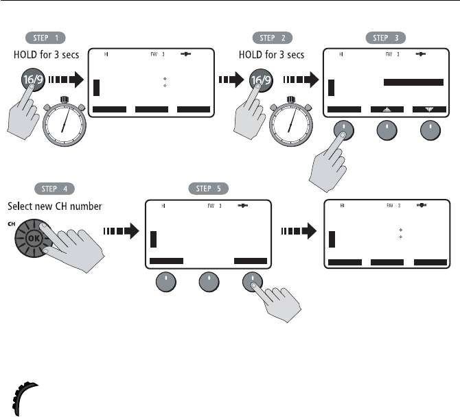
3.10 Selecting the Secondary Priority Channel
The Ray218/Ray55 enables you to program the 16/9 key to store a Secondary
Priority Channel. The default is CH 9. If on primary Priority CH16 or a working
channel, press and hold the 16/9 for 3 seconds to switch to the Secondary Priority
Channel at high power. The label 2ND PRIORITY appears. The default is CH 9.
.
If already tuned to the Secondary Priority Channel, press and release the 16/9 key
to switch to Priority Channel 16 at high power.
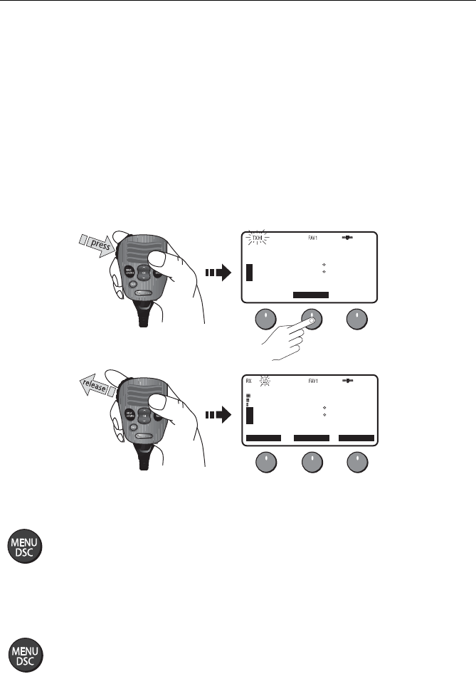
Reprograming the Secondary Priority Channel
1. Press and hold the 16/9 key for 3 seconds to switch to the current Secondary
Priority Channel.
2. Press and hold the 16/9 key for 3 seconds again to switch to Reprogram mode.
The message CHG 2ND PRI? appears with YES highlighted.
3. Press SELECT soft key to accept. The confirmation message CHANGE 2ND
PRIORITY CH appears.
4. Rotate the CH knob until the desired new secondary channel is shown.
5. Press the OK soft key to accept the new Secondary Priority selection.
16
26 06.0098N
080 04.8589W
AM10:43LOC
DISTRESS
A
CH68 CH79A CH71
U
S
A
CH69
D9159-1
1ST PRIORITY
09
26 06.0098N
080 04.8589W
AM12:45LOC
CALLING
A
CH68 CH79A CH71
U
S
A
CH69
D9160-1
PRESS and HOLD for 3 secs
10
15
20
25
30
35
40
45
50
55 60 5
2ND PRIORITY
Chapter 3: General Operations 37
3.11 Transmitting
Press and hold the Push-to-Talk (PTT) key on the microphone to transmit on the
selected channel, and then release to receive. The TX indicator appears during
transmission.
Note:
International regulations and good communications practice dictate that you not
interfere with other communications. Before transmitting, listen to make sure the channel
is clear.
The radio is equipped with a timeout timer in the event of a stuck key. After PTT
has been held continuously for 5 minutes, transmission is discontinued, the
message TX TIMEOUT appears, and the radio automatically returns to receive
mode.
After the timeout, the alarm continues to sound until PTT is released. The TX time
out timer is reset once the PTT key is released.
Note:
If the current channel is receive-only, an alert tone sounds when PTT is pressed, in-
dicating such a transmission is not permitted.
D9161-1
09
CALLING
B
A
U
S
A
A
26 06.5678N
080 04.8589W
AM10:33LOC
CH78A CH71
CH69
13
BRIDGE
B
A
U
S
A
A
CANCEL OK
CH69
CHANGE 2ND
PRIORITY CH
LEFT: 78A
PRESS OK
TO ACCEPT
09
CALLING
B
A
U
S
A
A
SELECT
CHG 2ND PRI?
YES
NO
13
BRIDGE
B
A
U
S
A
A
LEFT: 78A
CH78A CH71CH69
10
15
20
25
30
35
40
45
50
55 60 5
10
15
20
25
30
35
40
45
50
55 60 5
2ND PRIORITY
B
A
A
26 06.5678N
080 04.8589W
AM10:34LOC
2ND PRIORITY
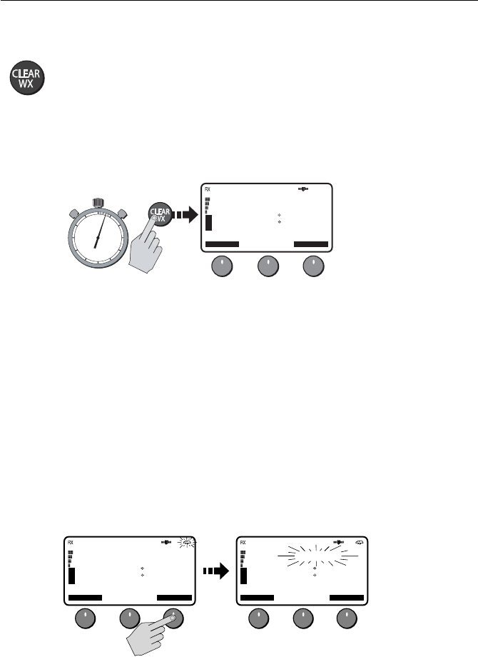
38 Ray218 and Ray55 VHF Radios
Overriding the Low Output Power Restriction
In the US, channels 13 and 67 are restricted to transmit at low power. However,
you can temporarily override this low power restriction. When you press PTT, a
new soft key appears in the middle position, labelled OVRIDE.
To override the LO power restriction on channels 13 or 67 and transmit at high
power:
1. Press and hold PTT. The OVRIDE soft key appears.
2. Press and release OVRIDE. The TX power is set to HI power for as long as you
hold down PTT.
When you release PTT, power returns to LO.
3.12 Menu Mode Operation
Press and release the MENU/DSC key while in standby mode to enter Menu
Mode.
Menu mode is fully described in Chapter 4.
3.13 DSC Call Operation
Press and hold the MENU/DSC key for greater than 3 seconds while in standby
operation mode to enter DSC Call Mode.
DSC Call mode is fully described in Chapter 5.
13
BRIDGE
A
CH68 CH79A CH71
U
S
A
OVRIDE
26 06.0098N
080 04.8589W
AM10:33LOC
D9250-1
13
BRIDGE
A
CH68 CH79A CH71
U
S
A
CH69
26 06.0098N
080 04.8589W
AM10:34LOC
Chapter 4: Menu Settings
4.1 Menu Function
Most of the radio’s functions reside in the Main Menu, which is accessed through
the MENU/DSC key. A diagram of the menu structure can be found in
Appendix C.
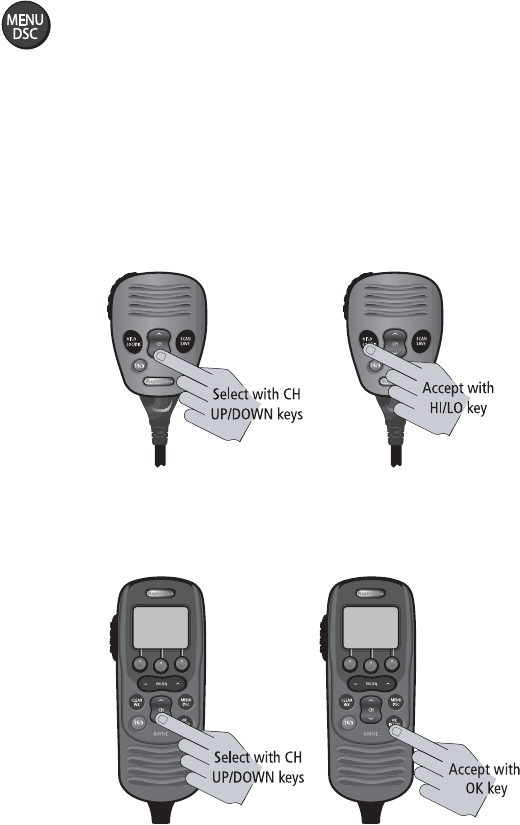
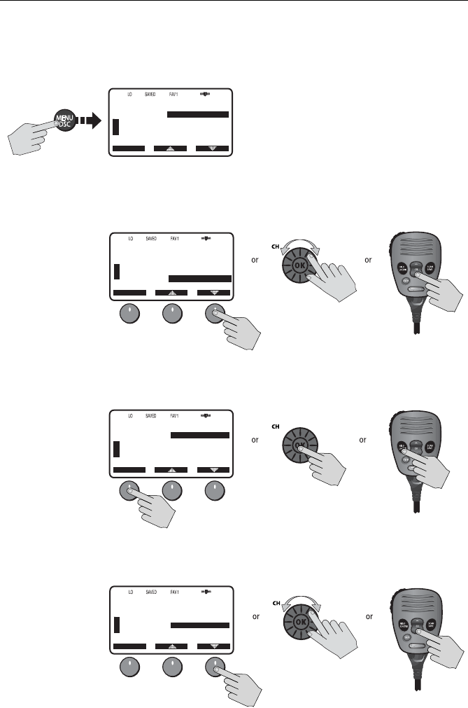
Making Menu and Programming Selections
There are three ways to make menu and character selections in your radio:
1. Most examples in this chapter describe making selections using the CH knob
and soft keys on the transceiver.
2. However, you can also press the microphone up/down keys to make your
selections and then press the microphone HI/LO key to accept.
3. Alternatively, if you have an optional RayMic, you can use its CH up/down
keys to select and OK key to accept.
D10023-1
D10022-1
40 Ray218 and Ray55 VHF Radios
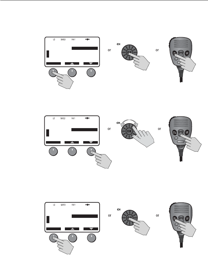
To make Menu selections:
1. Press and release the MENU/DSC key to enter Menu mode. The list of avail-
able menu groups appears.
2. Use the up/down arrow soft keys or CH knob on the transceiver or CH up/
down key on microphone (or RayMic) to scroll through the list until the
desired menu is highlighted.
3. Press SELECT or the CH knob on the transceiver or HILO key on microphone
(or OK key on RayMic) to accept. The sub-menu headings are displayed.
4. Use the up/down arrow soft keys or the CH knob on the transceiver or CH up/
down key on microphone (or RayMic) to highlight the desired sub-menu.
72
SHIP/SHIP
B
B
MAIN MENU
SELECT
VHF OPS
HAIL/FOG/IC
GPS SETUP
SYSTM CONFIG
[EXIT]
U
S
A
D9163-1
72
SHIP/SHIP
B
B
MAIN MENU
SELECT
HAIL/FOG/IC
GPS SETUP
SYSTM CONFIG
U
S
A
D9164-1
VHF OPS
[EXIT]
72
SHIP/SHIP
B
B
SYSTM CONFIG
SELECT
BACKLIGHT
CONTRAST
KEY BEEP
SIGNAL BAR
BEARING
U
S
A
D9165-1
72
SHIP/SHIP
B
B
SYSTM CONFIG
SELECT
BACKLIGHT
CONTRAST
KEY BEEP
SIGNAL BAR
BEARING
U
S
A
D9166-1
Chapter 4: Menu Settings 41
5. Press SELECT or the CH knob on the transceiver or HILO key on microphone
(or OK key on RayMic) to accept. The options under that sub-menu are dis-
played.
6. Use the up/down arrow soft keys or the CH knob on the transceiver or CH up/
down key on microphone (or RayMic) to highlight the desired option.
7. Press SELECT or the CH knob on the transceiver or HILO key on microphone
(or OK key on RayMic) to accept. The setting is changed. Continue in the same
manner to make any other setting changes.
To return to the previous menu level, select the [BACK] menu option or press the
CLEAR/WX key.
To exit the Menu mode, press the CLEAR/WX key again or else press the 16/9 key
to switch to the priority channel in standby mode.
72
SHIP/SHIP
B
B
KEY BEEP
SELECT
LOUD
QUIET
OFF
[BACK]
U
S
A
D9167-1
72
SHIP/SHIP
B
B
KEY BEEP
SELECT
LOUD
QUIET
OFF
[BACK]
U
S
A
D9168-1
72
SHIP/SHIP
B
B
KEY BEEP
SELECT
LOUD
QUIET
OFF
[BACK]
U
S
A
D9169-1
42 Ray218 and Ray55 VHF Radios
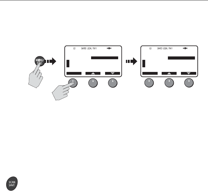
4.2 VHF Operations
This menu group controls basic radio functions. You access VHF Operations via
the MENU key.
Scan Mode
This function automatically searches through all channels in the set for any that
are broadcasting. If a transmission is received, the scan stops on the receiving
channel as long as it is present. If the signal is lost for five seconds, the radio
resumes scanning.
If you wish to temporarily remove a received channel from the scan so that the
scan no longer stops on this channel, press the XCLUDE soft key. The selected
channel is only excluded for the time you are currently in scan mode.
You can directly access the Scan Mode menu by pressing and releasing the SCAN/
SAVE key on the microphone. When a Scan Mode is active, you can terminate the
scan and return the radio to standby mode by pressing and releasing the key
again.
While scanning, press the microphone or RayMic CH up/down keys or rotate the
CH knob on the transceiver to change the scan direction. UP (key)/clockwise (CH
knob) increases the channel while DOWN (key) /counter-clockwise (CH knob)
decreases it.
Your Ray218/Ray55 is equipped with four types of scan options: All Scan, Saved
(Memory) Scan, Priority All Scan and Priority Saved Scan. The following
illustration demonstrates how to initiate All Scan but the procedure is the same
for all scan mode options.
Note:
Whenever Weather Alert is activated, the WX Alert channel is also monitored dur-
ing the Scan Modes. If the WX Alert tone is detected, the scan is halted to receive the
Weather Alert broadcast.
68
PLEASURE
B
B
MAIN MENU
SELECT
VHF OPS
HAIL/FOG/IC
GPS SETUP
SYSTM CONFIG
[BACK]
U
S
A
68
PLEASURE
B
B
VHF OPS
SELECT
SCAN MODE
DISPLAY MODE
HI/LO POWER
SAVE CHANNEL
WATCH MODE
U
S
A
D9170-1
Chapter 4: Menu Settings 43
To
terminate
the SCAN mode and return to standby mode, press:
• END soft key
•SCAN/SAVE key on the microphone
•CLEAR/WX key on the transceiver
•CLEAR/WX key on the optional RayMic
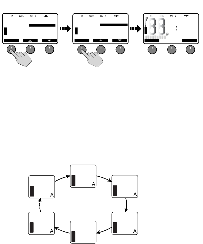
All Scan
In All Scan mode, all channels in the channel set are scanned in sequence. After
the last channel number has been scanned, the cycle repeats.
When active, SCAN ALL appears on the display.
71
PLEASURE
B
B
VHF OPS
SELECT
SCAN MODE
DISPLAY MODE
HI/LO POWER
SAVE CHANNEL
WATCH MODE
U
S
A
71
PLEASURE
B
B
SCAN MODE
SELECT
SCAN ALL
SCAN ALL+16
SCAN SAVE
SCAN SAVE+16
[BACK]
U
S
A
U
S
A
SCAN ALL
27 07.3838N
080 04.8499W
AM12:45LOC
END XCLUDE
D9171-1
SCAN ALL
U
S
A
01
SCAN ALL
U
S
A
88
SCAN ALL
U
S
A
03
SCAN ALL
U
S
A
07
SCAN ALL
U
S
A
05
SCAN ALL
U
S
A
06
D9172-1