Flir BelgiumBA WFBT10 Marine Multifunctional Display with 802.11b/g & Bluetooth User Manual 88038 1 EN GA150 installation instructions
Raymarine UK Ltd. Marine Multifunctional Display with 802.11b/g & Bluetooth 88038 1 EN GA150 installation instructions
Contents
- 1. 82314-1-EN a9x and a12x Supplementary information
- 2. 82327-1 RF Exposure - Addendum notice - DRAFT1
- 3. 88032-1-EN a9x a12x Mounting and getting started
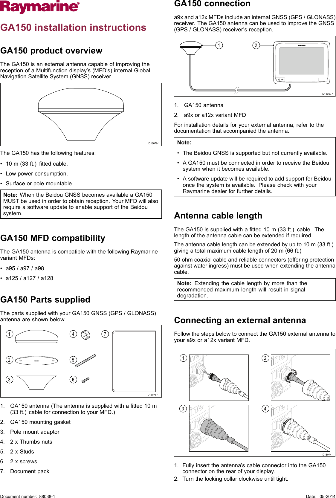
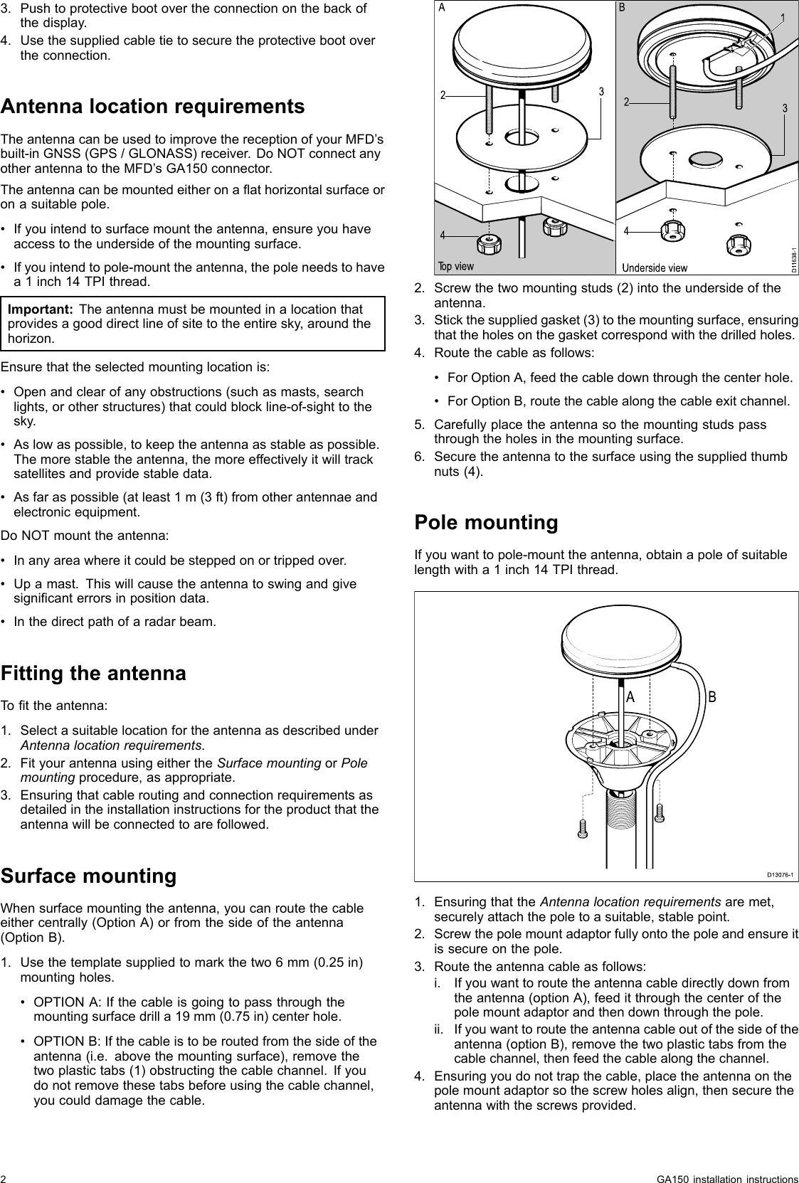
- 4. 88038-1-EN GA150 installation instructions
- 5. a-c-e Series Installation and operation instructions 81337-10-EN_WEB - part 1
- 6. a-c-e Series Installation and operation instructions 81337-10-EN_WEB - part 2
- 7. a-c-e Series Installation and operation instructions 81337-10-EN_WEB - part 3
- 8. a-c-e Series Installation and operation instructions 81337-10-EN_WEB - part 4
- 9. a-c-e Series Installation and operation instructions 81337-10-EN_WEB - part 5
88038-1-EN GA150 installation instructions